EP2267809A1 - Dispositif d'entraînement par inertie rotatif - Google Patents
Dispositif d'entraînement par inertie rotatif Download PDFInfo
- Publication number
- EP2267809A1 EP2267809A1 EP10179996A EP10179996A EP2267809A1 EP 2267809 A1 EP2267809 A1 EP 2267809A1 EP 10179996 A EP10179996 A EP 10179996A EP 10179996 A EP10179996 A EP 10179996A EP 2267809 A1 EP2267809 A1 EP 2267809A1
- Authority
- EP
- European Patent Office
- Prior art keywords
- actuator
- drive device
- rotor
- inertial drive
- rotary inertial
- Prior art date
- Legal status (The legal status is an assumption and is not a legal conclusion. Google has not performed a legal analysis and makes no representation as to the accuracy of the status listed.)
- Withdrawn
Links
- 230000033001 locomotion Effects 0.000 claims abstract description 45
- 230000001133 acceleration Effects 0.000 claims description 19
- 238000006073 displacement reaction Methods 0.000 abstract 1
- 238000013461 design Methods 0.000 description 4
- 230000003068 static effect Effects 0.000 description 4
- 230000005540 biological transmission Effects 0.000 description 3
- 238000010276 construction Methods 0.000 description 3
- 230000000694 effects Effects 0.000 description 3
- 239000000919 ceramic Substances 0.000 description 2
- 238000012552 review Methods 0.000 description 2
- 239000007787 solid Substances 0.000 description 2
- 238000013519 translation Methods 0.000 description 2
- 240000001439 Opuntia Species 0.000 description 1
- 235000004727 Opuntia ficus indica Nutrition 0.000 description 1
- 244000089486 Phragmites australis subsp australis Species 0.000 description 1
- 230000003321 amplification Effects 0.000 description 1
- 238000004891 communication Methods 0.000 description 1
- 238000013016 damping Methods 0.000 description 1
- 230000005684 electric field Effects 0.000 description 1
- 230000002349 favourable effect Effects 0.000 description 1
- 230000010354 integration Effects 0.000 description 1
- 238000004519 manufacturing process Methods 0.000 description 1
- 238000003199 nucleic acid amplification method Methods 0.000 description 1
- 230000000737 periodic effect Effects 0.000 description 1
- 238000012360 testing method Methods 0.000 description 1
- 230000003313 weakening effect Effects 0.000 description 1
Images


Classifications
-
- H—ELECTRICITY
- H02—GENERATION; CONVERSION OR DISTRIBUTION OF ELECTRIC POWER
- H02N—ELECTRIC MACHINES NOT OTHERWISE PROVIDED FOR
- H02N2/00—Electric machines in general using piezoelectric effect, electrostriction or magnetostriction
- H02N2/10—Electric machines in general using piezoelectric effect, electrostriction or magnetostriction producing rotary motion, e.g. rotary motors
- H02N2/101—Electric machines in general using piezoelectric effect, electrostriction or magnetostriction producing rotary motion, e.g. rotary motors using intermittent driving, e.g. step motors
Definitions
- the invention relates to a rotary inertial drive device with a stator and a rotor movably mounted relative to the stator, at least one actuator connected to the stator and a control unit for controlling the actuator.
- Inertia drive devices are, for example, from DW Pohl: Dynamic piezoelectric translation devices, in Review of Scientific Instruments, vol. 58 (1) January 1987, pages 54 to 57 and from Niedermann, R. Emch, P. Descouts: Simple piezoelectric translation device, in: Review of Scientific Instruments, vol. 59 (2) February 1988, pages 368-369 known.
- the basic principle of linear inertial drive devices is described in which a piezoelectric actuator is provided, which is acted upon by a sawtooth-like periodic signal and causes an acceleration relative to a frictionally connected to the actuator movably mounted part. At a low acceleration of the piezoelectric actuator, the movable part follows the actuator due to the frictional engagement.
- the movable member slips relative to the actuator as soon as the inertial force of the movable member becomes larger than the friction force between the movable member and the actuator.
- a rotary expression consists for example of a fixed stator and a movable rotor and a stator attached to the piezoceramic actuator. Due to the piezoelectric effect, the piezoceramic element is deformed. By applying the resonant frequency of a structure in contact with the rotor, an elliptical vibration can be generated which is transmitted to the rotor and causes the rotor to rotate.
- Such ultrasonic motors are for example in US 4,210,837 A . US 4,453,103 A . US 4,959,580 A . US 6,867,532 B2 and CA 2 416 628 A1 described.
- the drive principle of the ultrasonic motors is fundamentally different than the drive principle of rotary inertial drive devices.
- Inertia drive devices are divided into two subgroups, namely the impact-drive drives and the slip-stick drives.
- the Impact Drive drive consists of two bodies A and B, which are connected via a piezoceramic C.
- the body A is in contact with a surface over which it can slip when the static frictional force is overcome.
- the second body B which is not in contact with the surface, can be moved by the deformation of the piezoceramic.
- the acceleration of B is relatively low, the body A will not slip over the surface due to friction.
- the body A will slide over the surface because the inertial force of the body B is larger than the frictional force.
- the body B is alternately accelerated in one direction strong and less in the other direction, so a gradual movement of the entire structure can be achieved.
- Slip-stick drives are detailed in A. Bergander: “Control wear testing and integration of slip-stick micropositioning", Dissertation No. 2843, EPFL Lausanne, Switzerland, 2003 , as well as in the WO 2004/077584 described.
- the movement of the basically more efficient slip-stick drives is also composed of two types of movement, wherein a different arrangement of the components allows a better function of the positioner.
- an actuator D as a rule, a piezoelectric ceramic is fastened on one side to a non-movable mass.
- a body E is in frictional contact with the piezoceramic or with another light, firmly attached to the piezoceramic body.
- the piezoelectric ceramic is slowly deformed by the application of a gradually changing voltage, the body E is moved.
- This mode often becomes fine positioning mode or scan mode.
- the body E can be positioned with a very high resolution, smaller than one nanometer. However, the working area in this mode is usually limited to a few microns.
- the so-called rough positioning mode is used.
- the piezoceramic actuator D is deformed by a rapidly changing electrical voltage, thereby accelerating the mass of the body E. If the inertial force of the body E is greater than the static friction, there is a relative movement between the body E and the piezoceramic actuator D. If a high acceleration of the body E in one direction is followed by a slight acceleration in the opposite direction positioning over a theoretically unlimited work area.
- This construction has the advantage over the impact drive that the high possible resolution of the piezoceramic in the fine positioning mode can be used to position with just this high resolution.
- the arrangement of the components can be changed in the slip-stick drive, without violating the drive principle.
- a second possible configuration provides for the piezoceramic actuator or a light friction body attached to this actuator to be mounted movably on a surface or in a guide. On the other side of the actuator, another body is attached. By an asymmetrical control of the actuator, a high-resolution movement, especially in Feinpositioniermodus can be achieved.
- Slip-stick drives with which linear movements can be generated are, for example, in US 5,237,238 A1 .
- WO 00/54004 A1 WO 02/43162 A1 and WO 2004/077584 A1 also reveal slip-stick drives that can be used to create rotational movements and a combination of linear and rotary movements.
- Slip-stick drives are an easy way to position over long distances. By exploiting the small stroke of the piezoceramic to realize many small steps, macroscopic motions can be realized, as already described above.
- the piezoceramic arranged so that the stroke is either in the direction of movement of the linear movement or tangential to the rotation.
- the structure seems to act as if the direction of movement is deflected, in fact the stroke of the piezo element actually acts tangentially to the axis of rotation.
- the inertial drive device has a deflection between the stator and rotor, which is in frictional engagement with a friction surface of the rotor and is rigidly coupled to the actuator and for deflecting the direction of movement of the at least one Actuator is set up in a rotational movement, and that the control unit is arranged for acting on the at least one actuator with asymmetric control signals such that the rotor slow movements of the deflection follows due to the frictional engagement and fast movements of the deflection unit overcoming the frictional engagement does not follow.
- the inertial drives with inventive deflection unit have the advantage of a more compact design by a more favorable arrangement of the components.
- piezoceramics of any design can be used.
- the stroke of the piezoceramic can be structurally increased, maintained or reduced depending on the requirements.
- the stroke of the piezoceramic can be redirected to several friction contacts be so that large torques can be transmitted without individual friction contacts must be subjected to very large force.
- a rotary drive it is for example possible for a rotary drive to use a piezoceramic, which deforms radially to the axis of rotation.
- the deflection unit of the rotational inertial drive device is designed such that it is in constant frictional engagement with a friction surface of the rotor and is rigidly coupled to the actuator, so that upon application of the actuator with asymmetric control signals, the rotor follows movements as a result of low accelerations of the deflection due to the frictional engagement and movements due to high accelerations of the deflection unit overcoming the frictional engagement does not follow.
- the piezoceramic actuator of a rotational inertial drive device for this purpose usually has a high stiffness at low mass to implement the rapid changes in the drive signal from the actuator and to bring to the pursuit of the deflection.
- the ultrasonic drive on the other hand, it is not the stiffness of the actuator that is decisive, but a low degree of damping.
- the deflection unit is also as easy as possible, so that it can be moved quickly by the actuator with its limited power.
- the deflection must be as stiff as possible in their direction of movement in turn to be able to attach high accelerations on the frictional contact.
- the transmission links of the ultrasonic drives do not require high accelerations at the frictional contact. Rather, the transmission elements are tuned with respect to their resonance frequencies so that the desired mechanical vibration is obtained at the site of action.
- the deflection unit is configured to amplify or reduce the stroke of the at least one actuator. Lever action can thus be achieved with the deflection unit, so that a corresponding amplification or weakening of the movement can be achieved with very small deflections of the actuator.
- the deflection unit should be as stiff as possible in order to be able to attach high accelerations on the frictional contact.
- a labile structure of the deflection unit would not allow a movement according to the drive principle of the inertial drive.
- the symmetry axis of the at least one actuator and the axis of rotation of the rotor should preferably coincide. Thus, a uniform application of the rotor can be achieved with a torque without imbalances.
- the at least one actuator is preferably disc-shaped in a preferred embodiment and has a variable diameter, so that the direction of movement of the actuator is radially aligned. This has the advantage that acceleration forces can be applied over the entire circumference of the actuator, the stator formed by the actuator, the deflection unit coupled to the actuator and the rotor.
- the at least one actuator is rectangular and has a changeable length, so that the direction of movement is aligned in the length direction of the actuator.
- This embodiment offers the advantage that rectangular monolithic piezoceramics or a stacked piezoceramic can be used.
- the at least one actuator may also be annular or tubular and have a variable diameter, so that the direction of movement of the actuator is radially aligned.
- the deflection unit is preferably designed such that there is a frictional connection between the rotor and the deflection unit in each stroke position of the at least one actuator. Only by the inertia of the rotor, the frictional engagement between the rotor and deflection unit is then overcome, while still the frictional connection remains.
- the deflection unit has a base body connected to the stator and webs connected integrally with the base body, which extend in a diagonal direction at an angle to the radial or tangential Direction of the axis of rotation of the inertial drive device to the rotor extend.
- the deflecting unit preferably has at least one friction element connected to the webs and connected to the webs on the end of the webs opposite the web for connecting the webs to a friction surface which interacts with the rotor.
- the friction element is preferably a ring element integrally connected to the webs with a closed outer circumference, so that there is a frictional engagement on the entire circumference of the rotor, which is overcome by the inertia of the rotor during rapid movements of the actuator and the deflection unit.
- the rotor may be formed of two rotatably mounted about an axis, spaced from each other, disc-shaped tubular elements having a tapered inclined or curved portion in the radial outer region.
- a disk-shaped, variable in diameter actuator is mounted centrally on the axis and an annular deflection unit is seated on the outer circumference of the actuator.
- the deflection unit has diagonally outwardly projecting webs which are in frictional engagement with the inclined or curved portion of the rotor elements.
- the contact force between the deflection unit and the rotor elements is essentially defined by the inclined or curved portion.
- the contact pressure between the deflection unit and rotor elements can be easily adjusted by a further device.
- the at least one actuator can be a piezoceramic, electrostrictive or magnetostrictive actuator element.
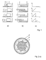
- FIG. 1 a shows the basic structure of an initially described Impact Drive drive consisting of two bodies A and B, which are connected via a piezoceramic C.
- the body A is in frictional connection with a plane.
- the acceleration of the body B, which is forced by the piezoceramic C, is relatively low, the body A will not slip over the surface due to the friction.
- acceleration will cause the body A to slide over the surface because the inertial force of the body B is greater than the frictional force.
- FIG. 1 b reveals the principle of slip-stick drives in which an actuator D is fixed on one side to a non-moving mass.
- the body E is in frictional contact with the actuator D.
- the actuator D is slightly accelerated by the application of a gradually changing voltage, the body E is moved.
- the inertial force of the body E is greater than the static friction, so that there is a relative movement between the body E and the actuator D.
- FIG. 1c allows the usual course of driving the illustrated inertial drives to be detected over time. It becomes clear that initially a slowly changing voltage is applied, which is abruptly reduced to an initial value after reaching a maximum voltage. In this phase, a high acceleration of the stator is achieved.
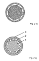
- FIG. 2 a) to c) show sketches of a rotary inertial drive device in side view.
- the in the FIG. 2 a) shown inertial drive device consists of a piezoelectric disc 1, which changes its diameter when subjected to a voltage.
- This disk 1 can be constructed monolithically or consist of several layers, if larger driving voltages should be avoided.
- the attached to the piezoelectric disc 1 boom a deflection unit 2 are compressed and bent. This takes place over the entire circumference of the piezoelectric disk 1, so that there is no significant eccentric movement. As a result, only the outer ring of the deflector 2 is rotated about the center.
- the angle at which the struts of the deflection unit 2 encounter the piezoelectric disc 1 it can be adjusted to what extent the movements of the piezoelectric disc 1 is deflected into a rotational movement of the outer ring.
- the outer ring constitutes a rotor 3 forming further body, which can be rotated after overcoming the static friction between the deflecting unit 2 and the rotor 3 around the center. In a relatively slow change in diameter of the piezoelectric disk 1, the rotor 3 is moved with the deflection unit 2.
- FIG. 2 b) shows the rotation of the deflection unit 2 about the center when the diameter of the piezoelectric disc 1 varies.
- the starting position is shown by the dashed lines.
- the finely shaded areas represent the state after the enlargement of the diameter.
- the Indian FIG. 2 a) sketched to be driven rotor 3 is in the FIG. 2 b) not shown for clarity.
- the resulting rotational movement is illustrated by two markings on the circumference.
- the dashed circle represents the initial position, while the solid circle shows the position after the increase of the diameter of the piezoelectric disc 1.
- the illustrated rotary inertial drive device consists of a piezoelectric disc 1 which changes its diameter when subjected to a voltage.
- This piezoelectric disc 1 may be constructed monolithically or consist of several layers, if larger driving voltages should be avoided.
- the movement of the piezoelectric disk 1 is deflected by a mechanical deflection unit 2 and distributed to a plurality of friction contacts, which are in frictional contact with the cylindrical rotor 3 to be rotated, so that the own movement of the slip-stick drives is possible. It is interesting that the deformation of the piezoelectric disk 1 over the entire circumference is divided among a plurality of friction bodies, each of which generates a proportion of the total torque of the drive.
- the deflecting unit 2 has at least one friction elements with a friction surface connected to the webs of the webs on the opposite end of the webs to connect the webs has, which cooperates with the rotor 3.
- FIG. 3 represents greatly simplified one of many possible constellations of the rotational inertial drive device.
- the actuator is in turn a circumferentially variable piezoelectric disc 1, while the deflection unit 2, the in the FIG. 2 a) sketched component with struts, which is connected to the piezoelectric disk 1.
- the rotor 3 is connected via a frictional contact with the deflection unit 2.
- the stator 4 is formed as a disc-shaped plate which is fixed relative to the piezoelectric disc 1, for example, by a shaft 5. In operation, a relative movement between the rotor elements 3 and the stator 4 are generated. It can be provided a device which makes it possible to adjust the contact force between the rotor elements 3 and the deflection unit 2. The contact force determines which moments the drive can transmit. Such a device for generating the contact pressure is not shown for the sake of clarity. There are many ways to adjust the contact pressure. For example, spring, screws or solid joints can be used.
- FIGS. 4 a) to c) show exemplary and sketchy some variants for the design of the contact area between the deflection unit 2 and the rotor elements 3.
- rotor 3 is formed of two rotatably mounted about an axis, spaced-apart disc-shaped rotor elements 3, which have a mutually tapered inclined or curved portion in the radially outer region.
- the annular deflection unit 2 is seated on the outer circumference of the actuator 1 and is in engagement with the inclined or curved portion of the rotor elements 3 with radially outwardly projecting webs.
- FIGS. 4 a) and b) Illustrated embodiments are suitable for the production of surface contacts.
- FIG. 4c) an example configuration for generating line contacts is outlined.
- a configuration for generating point contacts is not shown, but can be realized equally.
- FIG. 2 shows a side view, cross-sectional view and perspective view of an embodiment of the rotational inertial drive device in which more than one central piezo disk is used as the actuator 1. Unlike the in FIG. 3 shown constellation with only a piezoelectric disk without further storage can this z. As an increased lateral stiffness and a higher torque can be generated. This is achieved in that two opposing rotors 3 are provided with an intermediate disc-shaped stator 6. The rotors 3 are arranged rotatably about the shaft or axis 5.
- the rotors 3 move relative to the stator 6 about the central axis 5. If only the lateral stiffness to be increased, instead of a second drive unit and a stable storage can be used.
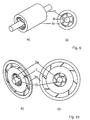
- FIGS. 6 a) and b) show another embodiment of the rotational inertial drive device in perspective view and side view.
- a rectangular monolithic piezoceramic actuator 1 or a stacked piezoelectric element 7 is used instead of the previously described piezoelectric disks. If the piezoelectric element 7 is subjected to a voltage, a relative rotation occurs between the piezoelectric element 7 and the deflection unit 7. Again, by adjusting the angle of the struts of the deflection unit 2 to the piezoelectric element 7, to what extent and with what leverage effect the stroke of the piezoelectric element 7 is to be transmitted in a rotation of the deflection unit 2.
- FIG. 7 leaves a side view of the deflecting element 2 FIG. 6 recognize with internal stacking piezoelectric element 7.
- the starting position is shown by the dashed lines.
- the finely shaded areas represent the state after the expansion of the stack piezo element 7.
- the resulting rotational movement of the deflection unit 2 is illustrated by the two markings on the circumference.
- FIGS. 8 a) and b) show another embodiment of the rotary inertial drive device in perspective view and side view.
- actuator 1 a piezo ring is used. If the piezo ring 8 is subjected to a voltage, then its inner and outer diameter varies. With such a piezo ring 8 drives can be realized as well as previously described above for the piezoelectric disk.
- FIGS. 9 a) and b) show another embodiment of the rotary inertial drive device in perspective view and side view.
- Piezo ring shown is used as an actuator Piezorschreibchen 11.
- the inner and outer diameters change again.
- the deflection unit 9 analogous to that in the FIG. 8 shown construction in the piezoelectric tube 11, a rotation can be achieved.
- the electrode can be segmented in the interior or exterior of the piezo tube 11, so that the middle part of the piezo tube 11 is not acted upon by an electric field.
- FIGS. 10 a) and b) show a further embodiment of the rotational inertial drive device in a perspective view and side view.
- the actuator 1 is designed as a central piezo ring, on the inner circumference of a first deflection unit 2 a engages, which is in communication with a shaft 10 for rotation thereof.
- a further deflection unit 2 b in the FIG. 2 provided type which acts as a stator and at the same time deflects the radial extent of the actuator 1 in a rotational movement.
- the embodiment of the inertial drive device is thus a combination of the in the Figures 2 and 8th illustrated embodiment.
- the change in the inner and outer diameter of the piezo ring when subjected to a voltage is thus exploited by the mechanical components already described above and in particular the deflection units 2 a and 2 b are used together.
Landscapes
- General Electrical Machinery Utilizing Piezoelectricity, Electrostriction Or Magnetostriction (AREA)
- Connection Of Motors, Electrical Generators, Mechanical Devices, And The Like (AREA)
- Linear Motors (AREA)
Applications Claiming Priority (2)
| Application Number | Priority Date | Filing Date | Title |
|---|---|---|---|
| DE102005040112 | 2005-08-24 | ||
| EP06775890A EP1984961B8 (fr) | 2005-08-24 | 2006-08-23 | Dispositif d'entrainement inertiel rotatif |
Related Parent Applications (1)
| Application Number | Title | Priority Date | Filing Date |
|---|---|---|---|
| EP06775890.4 Division | 2006-08-23 |
Publications (1)
| Publication Number | Publication Date |
|---|---|
| EP2267809A1 true EP2267809A1 (fr) | 2010-12-29 |
Family
ID=37616894
Family Applications (2)
| Application Number | Title | Priority Date | Filing Date |
|---|---|---|---|
| EP10179996A Withdrawn EP2267809A1 (fr) | 2005-08-24 | 2006-08-23 | Dispositif d'entraînement par inertie rotatif |
| EP06775890A Active EP1984961B8 (fr) | 2005-08-24 | 2006-08-23 | Dispositif d'entrainement inertiel rotatif |
Family Applications After (1)
| Application Number | Title | Priority Date | Filing Date |
|---|---|---|---|
| EP06775890A Active EP1984961B8 (fr) | 2005-08-24 | 2006-08-23 | Dispositif d'entrainement inertiel rotatif |
Country Status (3)
| Country | Link |
|---|---|
| EP (2) | EP2267809A1 (fr) |
| AT (1) | ATE551733T1 (fr) |
| WO (1) | WO2007022764A1 (fr) |
Families Citing this family (2)
| Publication number | Priority date | Publication date | Assignee | Title |
|---|---|---|---|---|
| DE102006052175B4 (de) * | 2006-11-02 | 2013-03-07 | SmarAct Holding GmbH | Trägheitsantriebsvorrichtung |
| DE102015208591B4 (de) * | 2015-05-08 | 2016-12-08 | Physik Instrumente (Pi) Gmbh & Co. Kg | Piezoelektrischer Drehantrieb mit einem als Blattfeder ausgebildeten Spannmittel |
Citations (15)
| Publication number | Priority date | Publication date | Assignee | Title |
|---|---|---|---|---|
| US4210837A (en) | 1979-03-08 | 1980-07-01 | Misikov Vitaly M | Piezoelectrically driven torsional vibration motor |
| US4453103A (en) | 1982-04-16 | 1984-06-05 | Kievsky Politekhnichesky Institut | Piezoelectric motor |
| US4959580A (en) | 1987-02-28 | 1990-09-25 | Kievsky Politekhnichesky Institut Imeni | Piezoelectric motor |
| WO1992010874A1 (fr) * | 1990-12-04 | 1992-06-25 | Scansov Transport Ab | Moteur piezoelectrique |
| DE4023311C2 (fr) | 1990-07-21 | 1992-12-17 | Omicron Vakuumphysik, 6204 Taunusstein, De | |
| US5410206A (en) | 1993-04-06 | 1995-04-25 | New Focus, Inc. | Piezoelectric actuator for optical alignment screws |
| EP0747977A1 (fr) | 1995-06-08 | 1996-12-11 | Minolta Co., Ltd. | Support mobile utilisant un transducteur électromécanique |
| WO1998019347A2 (fr) * | 1996-10-26 | 1998-05-07 | Artur Zrenner | Mecanisme d'entrainement par inertie, piezo-electrique ou electrostrictif pour deplacer et positionner des objets particulierement lourds |
| WO2000054004A1 (fr) | 1999-03-06 | 2000-09-14 | NMI Naturwissenschaftliches und Medizinisches Institut an der Universität Tübingen | Dispositif d'entrainement electromecanique dote d'un element piezo-electrique |
| CA2416628A1 (fr) | 2000-09-18 | 2002-03-28 | Eontech Group Inc. | Moteur piezoelectrique |
| WO2002043162A1 (fr) | 2000-11-23 | 2002-05-30 | Khaled Karrai | Dispositif de rotation inertielle |
| WO2004077584A1 (fr) | 2003-02-27 | 2004-09-10 | Ecole Polytechnique Federale De Lausanne (Epfl) | Dispositif d'actionnement piezo-electrique a trou passif pour un mouvement de pousser-tirer |
| US20050007683A1 (en) * | 2003-07-09 | 2005-01-13 | Ryu Jung Ho | Lens driving device |
| US6867532B2 (en) | 2003-07-17 | 2005-03-15 | The Brady Group Inc. | Long life piezoelectric drive and components |
| EP0823738B1 (fr) | 1996-08-05 | 2005-09-07 | attocube Systems AG | Positionneur inertiel |
-
2006
- 2006-08-23 WO PCT/DE2006/001471 patent/WO2007022764A1/fr active Application Filing
- 2006-08-23 EP EP10179996A patent/EP2267809A1/fr not_active Withdrawn
- 2006-08-23 EP EP06775890A patent/EP1984961B8/fr active Active
- 2006-08-23 AT AT06775890T patent/ATE551733T1/de active
Patent Citations (17)
| Publication number | Priority date | Publication date | Assignee | Title |
|---|---|---|---|---|
| US4210837A (en) | 1979-03-08 | 1980-07-01 | Misikov Vitaly M | Piezoelectrically driven torsional vibration motor |
| US4453103A (en) | 1982-04-16 | 1984-06-05 | Kievsky Politekhnichesky Institut | Piezoelectric motor |
| US4959580A (en) | 1987-02-28 | 1990-09-25 | Kievsky Politekhnichesky Institut Imeni | Piezoelectric motor |
| DE4023311C2 (fr) | 1990-07-21 | 1992-12-17 | Omicron Vakuumphysik, 6204 Taunusstein, De | |
| US5237238A (en) | 1990-07-21 | 1993-08-17 | Omicron Vakuumphysik Gmbh | Adjusting device for microscopic movements |
| WO1992010874A1 (fr) * | 1990-12-04 | 1992-06-25 | Scansov Transport Ab | Moteur piezoelectrique |
| US5410206A (en) | 1993-04-06 | 1995-04-25 | New Focus, Inc. | Piezoelectric actuator for optical alignment screws |
| EP0747977A1 (fr) | 1995-06-08 | 1996-12-11 | Minolta Co., Ltd. | Support mobile utilisant un transducteur électromécanique |
| EP0823738B1 (fr) | 1996-08-05 | 2005-09-07 | attocube Systems AG | Positionneur inertiel |
| WO1998019347A2 (fr) * | 1996-10-26 | 1998-05-07 | Artur Zrenner | Mecanisme d'entrainement par inertie, piezo-electrique ou electrostrictif pour deplacer et positionner des objets particulierement lourds |
| DE19909913B4 (de) | 1999-03-06 | 2004-01-15 | NMI Naturwissenschaftliches und Medizinisches Institut an der Universität Tübingen | Elektromechanische Antriebsvorrichtung |
| WO2000054004A1 (fr) | 1999-03-06 | 2000-09-14 | NMI Naturwissenschaftliches und Medizinisches Institut an der Universität Tübingen | Dispositif d'entrainement electromecanique dote d'un element piezo-electrique |
| CA2416628A1 (fr) | 2000-09-18 | 2002-03-28 | Eontech Group Inc. | Moteur piezoelectrique |
| WO2002043162A1 (fr) | 2000-11-23 | 2002-05-30 | Khaled Karrai | Dispositif de rotation inertielle |
| WO2004077584A1 (fr) | 2003-02-27 | 2004-09-10 | Ecole Polytechnique Federale De Lausanne (Epfl) | Dispositif d'actionnement piezo-electrique a trou passif pour un mouvement de pousser-tirer |
| US20050007683A1 (en) * | 2003-07-09 | 2005-01-13 | Ryu Jung Ho | Lens driving device |
| US6867532B2 (en) | 2003-07-17 | 2005-03-15 | The Brady Group Inc. | Long life piezoelectric drive and components |
Non-Patent Citations (2)
| Title |
|---|
| D. W. POHL: "Dynamic piezoelectric translation devices", REVIEW OF SCIENTIFIC INSTRUMENTS, vol. 58, no. 1, January 1987 (1987-01-01), pages 54 - 57 |
| REVIEW OF SCIENTIFIC INSTRUMENTS, vol. 59, no. 2, February 1988 (1988-02-01), pages 368 - 369 |
Also Published As
| Publication number | Publication date |
|---|---|
| EP1984961B8 (fr) | 2012-05-09 |
| EP1984961A1 (fr) | 2008-10-29 |
| WO2007022764A1 (fr) | 2007-03-01 |
| EP1984961B1 (fr) | 2012-03-28 |
| ATE551733T1 (de) | 2012-04-15 |
Similar Documents
| Publication | Publication Date | Title |
|---|---|---|
| EP1098429B1 (fr) | Moteur électromécanique | |
| EP0799502B1 (fr) | Element d'entrainement ou de reglage a actionnement piezo-electrique | |
| DE102006052175B4 (de) | Trägheitsantriebsvorrichtung | |
| EP2156480B1 (fr) | Dispositif d'actionnement piézoélectrique | |
| DE10017138C2 (de) | Taumelmotor | |
| EP2489081B1 (fr) | Actionneur | |
| DE19909913B4 (de) | Elektromechanische Antriebsvorrichtung | |
| EP1984961B1 (fr) | Dispositif d'entrainement inertiel rotatif | |
| WO2005074051A1 (fr) | Unite d'entrainement piezoelectrique et procede pour produire un mouvement d'entrainement de preference rotatif d'une telle unite d'entrainement | |
| DE102006045293B4 (de) | Festkörperaktor-Antriebsvorrichtung | |
| EP3301730B1 (fr) | Convertisseur d'énergie | |
| DE19710601C2 (de) | Bewegungsgenerator | |
| WO2021164799A1 (fr) | Moteur à ultrasons piézoélectrique | |
| EP2356705A2 (fr) | Entraînement universel électrique de piézomoteur | |
| EP2277210A1 (fr) | Mécanisme d'entraînement en rotation | |
| DE102005032957B4 (de) | Festkörperaktor-Antriebsvorrichtung | |
| EP2027614A1 (fr) | Dispositif d'entraînement d'actionneur de corps fixe | |
| DE112010005916T5 (de) | Elektromechanischer Aktuator | |
| DE102013112526A1 (de) | Antriebsvorrichtung zur Erzeugung einer Drehbewegung - insbesondere Antriebsvorrichtung für eine Scheibenbremse | |
| EP1152522A2 (fr) | Mécanisme d'entraínement électromécanique | |
| DE10156836B4 (de) | Vorrichtung zur Erzeugung einer rotatorischen Bewegung und Verwendung derselben | |
| DE102005023988B4 (de) | Piezoelektrischer Motor | |
| EP2112759A2 (fr) | Moteur piézoélectrique | |
| DE102008001405A1 (de) | Piezoelektrische Antriebsvorrichtung, sowie Verfahren zum Betreiben einer solchen | |
| DE102007021336A1 (de) | Piezoelektrische Antriebsvorrichtung |
Legal Events
| Date | Code | Title | Description |
|---|---|---|---|
| PUAI | Public reference made under article 153(3) epc to a published international application that has entered the european phase |
Free format text: ORIGINAL CODE: 0009012 |
|
| 17P | Request for examination filed |
Effective date: 20100927 |
|
| AC | Divisional application: reference to earlier application |
Ref document number: 1984961 Country of ref document: EP Kind code of ref document: P |
|
| AK | Designated contracting states |
Kind code of ref document: A1 Designated state(s): AT BE BG CH CY CZ DE DK EE ES FI FR GB GR HU IE IS IT LI LT LU LV MC NL PL PT RO SE SI SK TR |
|
| 17Q | First examination report despatched |
Effective date: 20110912 |
|
| RAP1 | Party data changed (applicant data changed or rights of an application transferred) |
Owner name: SMARACT GMBH |
|
| STAA | Information on the status of an ep patent application or granted ep patent |
Free format text: STATUS: THE APPLICATION IS DEEMED TO BE WITHDRAWN |
|
| 18D | Application deemed to be withdrawn |
Effective date: 20120323 |