EP2267743A1 - Power cutter switch - Google Patents
Power cutter switch Download PDFInfo
- Publication number
- EP2267743A1 EP2267743A1 EP10165145A EP10165145A EP2267743A1 EP 2267743 A1 EP2267743 A1 EP 2267743A1 EP 10165145 A EP10165145 A EP 10165145A EP 10165145 A EP10165145 A EP 10165145A EP 2267743 A1 EP2267743 A1 EP 2267743A1
- Authority
- EP
- European Patent Office
- Prior art keywords
- cam
- switch
- actuator
- movement
- knob
- Prior art date
- Legal status (The legal status is an assumption and is not a legal conclusion. Google has not performed a legal analysis and makes no representation as to the accuracy of the status listed.)
- Granted
Links
Images


Classifications
-
- H—ELECTRICITY
- H01—ELECTRIC ELEMENTS
- H01H—ELECTRIC SWITCHES; RELAYS; SELECTORS; EMERGENCY PROTECTIVE DEVICES
- H01H25/00—Switches with compound movement of handle or other operating part
- H01H25/06—Operating part movable both angularly and rectilinearly, the rectilinear movement being along the axis of angular movement
- H01H25/065—Operating part movable both angularly and rectilinearly, the rectilinear movement being along the axis of angular movement using separate operating parts, e.g. a push button surrounded by a rotating knob
-
- B—PERFORMING OPERATIONS; TRANSPORTING
- B23—MACHINE TOOLS; METAL-WORKING NOT OTHERWISE PROVIDED FOR
- B23D—PLANING; SLOTTING; SHEARING; BROACHING; SAWING; FILING; SCRAPING; LIKE OPERATIONS FOR WORKING METAL BY REMOVING MATERIAL, NOT OTHERWISE PROVIDED FOR
- B23D45/00—Sawing machines or sawing devices with circular saw blades or with friction saw discs
- B23D45/16—Hand-held sawing devices with circular saw blades
-
- B—PERFORMING OPERATIONS; TRANSPORTING
- B25—HAND TOOLS; PORTABLE POWER-DRIVEN TOOLS; MANIPULATORS
- B25F—COMBINATION OR MULTI-PURPOSE TOOLS NOT OTHERWISE PROVIDED FOR; DETAILS OR COMPONENTS OF PORTABLE POWER-DRIVEN TOOLS NOT PARTICULARLY RELATED TO THE OPERATIONS PERFORMED AND NOT OTHERWISE PROVIDED FOR
- B25F5/00—Details or components of portable power-driven tools not particularly related to the operations performed and not otherwise provided for
-
- H—ELECTRICITY
- H01—ELECTRIC ELEMENTS
- H01H—ELECTRIC SWITCHES; RELAYS; SELECTORS; EMERGENCY PROTECTIVE DEVICES
- H01H3/00—Mechanisms for operating contacts
- H01H3/02—Operating parts, i.e. for operating driving mechanism by a mechanical force external to the switch
- H01H3/022—Emergency operating parts, e.g. for stop-switch in dangerous conditions
-
- H—ELECTRICITY
- H01—ELECTRIC ELEMENTS
- H01H—ELECTRIC SWITCHES; RELAYS; SELECTORS; EMERGENCY PROTECTIVE DEVICES
- H01H3/00—Mechanisms for operating contacts
- H01H3/32—Driving mechanisms, i.e. for transmitting driving force to the contacts
- H01H3/42—Driving mechanisms, i.e. for transmitting driving force to the contacts using cam or eccentric
Definitions
- the present invention relates to a switch mechanism, in particularly to a switch mechanism for a power tool such as a power cutter.
- a typical power cutter comprises a housing in which is mounted a two stroke internal combustion engine. Attached to the side of the housing is a support arm which extends forward of the housing. Rotatably mounted on the end of the support arm is a cutting blade, usually in the form of a grinding disk.
- the motor is drivingly connected to the cutting blade via a drive belt.
- the rotary output of the engine rotatingly drives the cutting blade via the drive belt.
- the drive belt is driven via a centrifugal clutch which enables the output drive spindle of the engine to disengage from the belt when the engine is running at a slow speed, to allow the engine to continue running, whilst allowing the blade to be stationary.
- a petrol tank which provides petrol for the engine via a carburettor.
- An oil tank can also be provided, which provides lubricating oil to mix with the petrol, to lubricate the engine.
- a rear handle for supporting the power cutter, which contains a trigger switch for accelerating the engine upon depressing. Depression of the trigger switch causes more of the aerated petrol/oil mixture to be injected into the engine which in turn causes the speed of the engine to accelerate.
- Power cutters are typically started using a pull cord. Once started, the engine will continue to run in an idle mode until stopped. It is important to provide a switching mechanism which prevents the power cutter from being started when it is the OFF position, and which allows it to be started when it is in the ON position. The switching mechanism is also used to stop the engine when it is running by being switched from its ON position to its OFF position. However, it is desirable to be able to switch the engine off quickly during an emergency situation.
- the present invention provides a simplified design of ON/OFF switching mechanism to that disclosed in UK patent application no. 0812274.9 and which is less prone to failure due to dust and debris.
- a switch mechanism comprising a support structure; an electric switch mounted on the support structure and which comprises an activator moveable between a first position where the electric switch is switched on and a second position where the electric switch is switched off; a first actuator moveably mounted on the support structure; a cam, having a cam surface, connected to the first actuator so that movement of the first actuator results in movement of the cam; a second actuator moveably mounted on the support structure; a bar connected to the second actuator so that movement of the second actuator results in movement of the bar; wherein the cam is capable of engaging with the activator so that movement of the cam by movement of the first actuator results in the activator moving between its two positions; wherein the bar is capable of engaging with the activator so that movement of the bar by movement of the second actuator results in the activator moving between its two positions; wherein the bar passes through or alongside the surface of the cam when it engages the activator.
- a power tool comprising a switch mechanism as claim in any one of claims wherein;
- the power tool can be a power cutter.
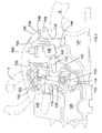
- FIG 1 shows a power cutter which comprises a housing 800 in which is located a two stroke engine, a rear handle 802, a support arm 804 and a front handle 806.
- a cutting blade 808 is rotatably mounted on the support arm and which can be driven by the engine.
- a guard 810 surrounds the top part of the blade 808.
- the two stroke internal combustion engine is fed with an air/petrol mixture from a carburettor 126.
- the engine burns the mixture in well known manner to generate rotary motion of its crank shaft 114, which connects to an output shaft.
- the exhaust gases are then expelled from the engine through an exhaust 146 to the surrounding atmosphere.
- the engine is started using a pull cord in well know manner.
- the power cutter will comprise a petrol tank 124 in which is located petrol for driving the two stroke internal combustion engine 24. Petrol will pass from the tank 124 via passageway 144 through the carburettor 126 which will mix it with air from an air filter 890, prior to being forwarded to the cylinder 120 where it will be burnt.
- a second tank 128 will also be mounted in the body as shown in which lubricating oil will be contained. The oil will be pumped out of the tank 128 via an oil pump 700.
- the oil pump 700 will pump the oil through the oil passageways indicated by lines 142 from the oil tank 128 via the pump 130 into the passageway 132 between the carburettor 126 and the cylinder 120, in a suitable form, for example, as a spray or atomized, which is then mixed with the air/petrol mixture generated by the carburettor 126.
- a sensor 140 is mounted within the passageway 132 between the carburettor 126 and cylinder 120. The sensor monitors the amount of oil being added to the petrol/air mixture and sends a signal, via an electric cable 701, indicative of the amount of oil in the passageway 132 back to an electronic controller 716 (see Figure 3 ).
- Such a sensor can be of a capacitance type whereby the sensor monitors the change in capacitance between two plates, the capacitance being a function of the amount of oil there is in the petrol/air mixture.
- the carburettor 126 is a standard design which, during normal operation, operates with out any external power input. However, the carburettor 126 comprises a solenoid 714. There are a number of ways a carburettor can use a solenoid, two of which are:
- the engine ignition system is controlled by an electronic controller 716, the function of which is described in more detail below with reference to Figure 3 .
- a fly wheel 702 which contains a number of metal fins 704 which form an impeller. As the fly wheel 702 rotates, the impeller blows air around the out side of the engine. Adjacent the impeller 702 are two generators 706; 708. The two generators generate electricity using magnets and the change of inductance caused by the rotating flywheel 702. As the fly wheel 702 rotates, it causes the two generators 706; 708 to produce electricity.
- the first generator 706 is used to provide electricity for the ignition system of the engine and the electronic controller 716.
- the second generator 708 is used to provide electricity for the oil pump 700 and the solenoid 714 in the carburettor. Both are connected to the electronic controller 716 via cables 717.
- the two generators 706; 708 will be off-the-shelf products.
- the first sensor 710 monitors the temperature of the engine block and sends a signal via an electric cable 711 indicative of the temperature to the electronic controller 716.
- the second sensor 712 monitors the angular position of the flywheel 702 and sends a signal via an electric cable 713 indicative of the angular position of the flywheel 702 back to the electronic controller 716. This signal can also be used by the electronic controller 716 to determine the rate of rotation of the fly wheel 702, as well as its angular position.
- the oil pump 700 is an electrically powered oil pump 700, the power for which is supplied by the electronic controller 716 via electric cable 715.
- the oil pump is shown in Figure 4 . This type of oil pump is described in EP1236894 and therefore further explanation of its construction will not be described in detail.
- the oil pump 700 is driven by the electronic controller 716 which sends a square shaped voltage signal 892 to the oil pump (see Figure 14A ) When the voltage is at V1, it causes the piston 850 of the pump to move, reducing the size of the oil chamber 852. This causes a preset amount of oil to be pump out of the chamber 852. When voltage is "0", the piston returns to its starting position due to the spring 854, enlargening the chamber 852 and allowing the chamber 852 to fill with oil.
- the oil pump is capable of running at two speeds (the first speed shown in Figure 14A , the second speed being shown in Figure 14B where the frequency of the square shaped volge signal 892, and hence the movement of the piston 850, is double) and its general operation is described in more detail below.
- the spark plug 730 is connected to the electronic controller 716 via a cable 732. Ignition of the spark plug is controlled by the electronic controller 716.
- a primer 734 is mounted on the rear wall 736 of the housing 800 of the power cutter.
- the primer is a manual pump.
- a pipe 738 connects from the petrol tank 124 to the primer 734.
- a second pipe 740 connects from the primer to the carburettor 126.
- the primer consists of two valves 742; 744 located in series which allow the petrol to flow one way through them only (indicated by Arrows A and B).
- Located between the two valves 742; 744 is a chamber 750 having a rubber dome 746 forming a wall which is accessible to the user of the power cutter.
- One valve 742 only allowing petrol to enter the chamber 750, the other only allowing petrol to leave the chamber 750.
- the operator compresses the rubber dome 746 (shown as dashed lines 748). This reduces the amount of volume in the chamber 750 formed between the valves and hence the amount of space which can contain petrol.
- petrol is ejected from the primer through the one of the valves 744, as the second valve 742 remains closed, preventing petrol from leaving the chamber 750 via that valve 742.
- the volume of the chamber 750 increases, causing petrol to be sucked into the chamber 750 through the second valve 742 as the first valve remains closed 744 preventing petrol from entering the chamber 750 through that valve 744.
- Repetitive compressing and releasing of the dome 746 results in the petrol being pumped through the primer 734.
- the primer is arranged so that the operator can manually pump the petrol from the tank 124 to the carburettor 126 through the pipes 738; 740.
- the purpose of the primer is to enable the operator to place petrol into the carburettor. Otherwise the operator has to spin the engine a number of times using the pull cord before a sufficient amount of petrol is sucked through into the carburettor 126.
- a DECO valve 752 is mounted on the side of the cylinder 120.
- the valve 752 is opened manually by the operator prior to starting the engine.
- the DECO valve reduces the pressure within the cylinder 120 prior to ignition. This enables the starting of the engine using the pull cord to be made easier as the amount compression of the petrol/air mixture required is reduced.
- the DECO valve automatically closes.
- the electronic controller 716 has an on/off switch 754 in the form of a rotatable knob 758.
- the switch is connected to the electronic controller via an electric cable 756.
- the knob 758 as a pointer 764 integrally formed on its periphery.
- the rotatable knob 758 has two angular positions between which it can rotate. In the first position, the switch is ON. In this position, the pointer 764 points to an ON label 762 (see Figure 1 ). In the second position, the switch is OFF. In this position, the pointer 764 points to an OFF label 760.
- the rotatable knob is in the ON position, the operator can start the engine and use the power cutter.
- the rotatable knob 758 is in the OFF position, the engine is prevented from being started. If the rotatable knob 758 is moved from the ON to the OFF position when the engine is running, the engine is automatically switched off.
- a safety button 766 is located in the centre of the knob 758. If the engine is running (ie the knob is in the ON position), depression of the safety button 766 will result in the engine being switched off. The knob 758 then automatically returns to the OFF position. If the knob 758 is prevented from returning to the OFF position after the safety button has been depressed, the engine will not be able to be started until the knob 758 has been allowed to return to the OFF position.
- the ON/OFF switch assembly consists of the rotatable knob 758, a crank 768, a switch cam 770 and the safety button 766.
- the crank 768 is rigidly fixed into the rear wall 736 of the housing 800 and prevented from rotation.
- the crank 768 comprises a socket 772 into which is rigidly mounted a micro switch 774 (see Fig 8C ).
- Rotatably mounted on the outside of the crank 768 is the knob 758.
- Rotatably mounted on the inside of the crank 768 is the switch cam 770.
- a bolt 778 which passes through the base of a tubular recess 776 formed in the knob 758, screws into the switch cam 770 and is rigidly attached to it.
- Sandwiched between the head of the bolt 778 and the base of the recess 776 is a spring 780.
- the bolt 778 and spring 780 hold the knob 758 and switch cam 770 onto the crank 768, biasing them towards each other as the spring biases the head of the bolt 778 away from the base of the recess 776.
- the knob can rotate through a limited range of movement (between the ON and OFF positions) relative to the crank 768.
- the range of positions is limited by pegs 786 formed on the underside of the knob engaging with recesses 788 formed in the edge of the rear wall 736 of the housing.
- the switch cam 770 can also rotate through a limited range of movement relative to the crank 768.
- the switch cam 770 can axially slide relative to the crank 768 in a direction parallel to the longitudinal axis of the bolt 778 over a limited range of movement, the range being limited by the length of the bolt 778 within the recess 776.
- the bolt 778 rotates and slides with the switch cam 770.
- the safety button 766 is mounted within the tubular recess 776 formed in the knob 758 and encloses the end of the bolt 778 located in the recess776 and the spring 780 (see Fig 9 ).
- the safety button 766 can axially slide within the recess 776 towards or away from the switch cam 770.
- the range of outward axial movement of the safety button is limited by stops 782 each engaging with an inner step of the knob 758.
- the head of the bolt 778 directly abuts the underside of the safety button 766. Depression of the safety button, causes the bolt 778 to be pushed through the base, compressing the spring 780, moving the switch cam 770 away from the crank768 and knob 758.
- a long helical spring 784 Connected between the knob 758 and the crank 768 is a long helical spring 784.
- the helical spring 784 locates in a circular channel 790 formed on the underside of the knob 758 as best seen in Figure 10 .
- One end abuts against a wall 792 at the end of the channel 790.
- the other end abuts against a stop (not shown) formed on the crank 772.
- the spring 784 rotationally biases the knob 758 relative to the crank to its OFF position.
- a leaf spring 794 Connected between the switch cam 770 and the crank 768 is a leaf spring 794 as best seen in Figures 12 and 13 .
- One end of the leaf spring 794 is connected using a small bolt 796 to the switch cam 770.
- the other end abuts a stop 798 on the crank 768.
- the leaf spring 794 rotationally biases the switch cam 770 relative to the crank to an OFF position.
- each of the two ramps 820 is located in a corresponding ramp recess 824 with the ramp ends 822 of each ramp 820 abutting directly against the ramp recess ends 826 of the corresponding ramp recess 824.
- crank ramps 828 Formed on the underside of the crank 768 are two crank ramps 828, each ramp 828 having a crank ramp end 830 as best seen in Figure 8C .
- switch cam crank ramps 832 Formed on the side of the switch cam 770 which faces the knob 758 are switch cam crank ramps 832 which have switch cam crank ramp ends 834 as best seen in Figure 9 .
- the micro switch 774 comprises a pin 838 which projects from the body of the micro switch 774.
- the pin 838 is capable of sliding axially in or out of the body of the micro switch 774 and biased to its outer most position by a spring (not shown) inside the micro switch 774.
- the pin 838 engages the peripheral cam 836. Rotation of the switch cam 770 causes the pin 838 to slide along the peripheral cam 836, which causes it to be pushed into the body of the micro switch 774 against the biasing force of the spring, or allows it to slide out of the body of the micro switch 774 under influence of the spring.
- the knob 758 and the switch cam 770 are both located in their OFF positions.
- the operator of the power cutter desires to turn the unit on using the ON/OFF switch.
- the operator uses their hand to rotate the knob 758 from its OFF position to its ON position.
- the knob 758 When the knob 758 is rotated, it causes the cam switch 770 to rotate in unison as the rotary movement is transferred from the knob 758 to switch cam 770 by the ramp ends 822 of each ramp 820 pushing the ramp recess ends 826 of each corresponding ramp recess 824, against which it abuts, in the direction of Arrow M in Figure 9 , to cause the switch cam 770 to rotate with the knob 758.
- the switch cam 770 When the switch cam has rotated sufficiently that the crank ramp ends 830 and the switch cam crank ramp ends 834 become aligned, the switch cam 770 axially slides under the biasing force of the spring 780 towards the knob 758, ensuring that the crank ramp end 830 and the switch cam crank ramp ends 834 abut against each other as shown in Figure 8E .
- the switch cam 770 When the crank ramp endS 830 and the switch cam crank ramp ends 834 abut each other as shown in Figure 8E , the switch cam 770 is in its ON position and is prevented from returning to its OFF position, under the influence of the leaf spring 794, as the crank ramp endS 830 and the switch cam crank ramp ends 834 prevent relative movement as they are jammed against each other.
- the knob 758 is prevented from returning to its OFF position under the influence of the spring 784 by the ramps 820 being held within the ramp recesses 824 by the action of the spring 780 which overrides the spring 784.
- the switch cam 770 rotates from the OFF position (see Figure 8A ) to the ON position ( Figure 8B )
- the peripheral cam 836 rotates, which in turn allows the pin 838 to extend from the body of the micro switch 774. This in turn makes a connection which allows the electric controller 716 to activate the power cutter and allow it to start when the pull cord is pulled.
- the assembly of the ON/OFF switch is now ON with the knob 758 and the switch cam 770 both in their ON positions, allowing the pin 838 to extend from the body of the micro switch 774. There are two way of switching the ON/OFF switch assembly to its OFF position.
- the first method comprises the depression of the safety button 766. Depression of the safety button 766 causes the head of the bolt 778 to slide towards the base of the recess 776 of the knob 758, compressing the spring 780, which in turn causes the switch cam 770 to axially slide away from the knob 758. As the switch cam 770 axially slides, the switch cam 770 moves away from the crank 768, which in turn causes the crank ramps 828 and the switch cam crank ramps 832 to move away from each other, and thus causes the crank ramp ends 830 and the switch cam crank ramp ends 834 to disengage. As such, the switch cam 770 can now rotate back to its OFF position under the influence of the leaf spring 794.
- the knob 858 will also return to its OFF position as the ramp recesses 824 rotate with the switch cam 770. Should the ramps 820 become disengaged from the ramp recesses 824 due to the sliding movement of the switch cam 770 relative to the knob 758, the knob 758 will return to its OFF position under the influence of the spring 784 between the knob 758 and the crank 768.
- the second method of switching the ON/OFF switch assembly OFF comprises the rotation of the knob 758.
- the operator rotates the knob 758 to its OFF position.
- rotation of the knob 758 urges rotation of the switch cam 770.
- the switch cam 770 is prevented from rotating as the crank ramp ends 830 and the switch cam crank ramp ends 834 abut each other. Therefore, the ramps 820 slide out of the ramp recesses 824, the ramp ends 822 moving away from ramp recess ends 826.
- the switch cam 770 As the ramps 820 slide out of the ramp recesses 824, the switch cam 770, which is prevented from rotating, axially slides away from the knob 858 by the caming action of the ramps 820 and ramp recesses 824.
- the switch cam 770 When the switch cam 770 has slid sufficiently far enough away from the knob 758, the crank ramp ends 830 and the switch cam crank ramp ends 834, which are sliding away from each other, become disengaged.
- the switch cam 770 can rotate under the influence of the leaf spring 794 to its OFF position.
- the knob 758 will move under the influence of the operator and/or the spring 784. As such, both the knob 758 and the switch cam 770 return to their OFF position where they are held by the springs 784; 794.
- the operator first activates the DECO valve 752 and then pumps some petrol into the carburettor 126 using the primer 734. The operator then switches the ON/OFF switch to ON by rotation of the knob 758 to its ON position. The operator then pulls the pull cord to rotate the crank 114 of the engine. As the crank 114 rotates, the fly wheel 702 also rotates causing the two generators 706; 708 to produce sufficient electricity to operate the power cutter.
- the electronic controller checks the temperature of the engine using sensor 710. If the engine is cold, it uses the electricity from the second generator 708 to power the solenoid 714 in the carburettor to set the "automatic choke". The second generator 708 is not powerful enough to power both the oil pump 700 and solenoid 714 at the same time. Therefore, when the electronic controller 716 is operating the solenoid 714, it switches off the oil pump 700. It has been found that the period during which lubricating oil is not required before the engine is damaged is greater than that required to heat up the engine.
- the electronic controller supplies the power to the spark plug to cause combustion in the engine, the power being provided by the first generator 706, the timing being determine by the electronic controller 716 based on the signal provided by the sensor 712 in relation to the angular position of the fly wheel 702.
- the DECO valve automatically closes.
- the electronic controller 716 continues to monitor the engine temperature and when it has reached a predetermine temperature, the electronic controller 716 switches the solenoid 714 in the carburettor 126 off.
- the electronic controller 716 then commences supplying a square shape voltage signal to the oil pump to commence pumping oil.
- the electronic controller monitors the speed of the engine using the signal provided by the sensor 712 monitoring the angular position of the fly wheel 702 to calculate the rotational speed. If the rotational speed is below a predetermined value, the electronic controller 716 sends a signal ( Figure 14A ) to the oil pump 700 to cause it to pump at a slow speed..
- the electronic controller 716 sends a signal ( Figure 14B ) to the oil pump 700 to cause it to pump at a higher speed.
- the speed of the engine is dependent on the operator squeezing a trigger switch which connects to the carburettor via a cable.
- the electronic controller 716 monitors the oil being added to the petrol/air mixture using the sensor 140. If the sensor 140 detects that the rate of flow of the oil being pumped by the oil pump 700 has dropped below a predetermine amount (eg there is a blockage in the oil pipe142 or the tank 128 is empty), the electronic controller places the engine into an idle mode using the ignition system so that the engine runs, but at a minimal rate. The operator can not speed up the engine using the trigger until the sensor 140 detects the flow of oil. This protects the engine from damage due to a lack of lubrication. It has been found that the engine can run in idle mode for a considerable period of time before damage to the engine results.
- a predetermine amount eg there is a blockage in the oil pipe142 or the tank 128 is empty
- the operator In order for the operator to stop the power cutter, the operator either depresses the safety button 766 or rotates the knob 758 to its OFF position.
- the switch 754 comprises a rotatable knob 758.
- the knob 758 has a pointer 764 integrally formed on its periphery.
- the rotatable knob 758 has two angular positions between which it can rotate. In the first position, the switch is ON. In this position, the pointer 764 points to an ON label 762 (see Figure 19A ). In the second position, the switch is OFF. In this position, the pointer 764 points to an OFF label 760 (see Figure 17A ).
- the rotatable knob is in the ON position, the operator can start the engine and use the power cutter.
- the rotatable knob 758 is in the OFF position, the engine is prevented from being started. If the rotatable knob 758 is moved from the ON to the OFF position when the engine is running, the engine is automatically switched off.
- a safety button 766 is located in the centre of the knob 758. If the engine is running (ie the knob is in the ON position), depression of the safety button 766 will result in the engine being switched off.
- a circular hole 900 is formed through the rear wall 736 of the housing 800.
- the rotatable knob 758 is mounted onto the outside of the rear wall 736 adjacent the circular hole 900.
- a cam wheel 902 is rotatably mounted on the inside of the rear wall 736 adjacent the circular hole 900.
- Two screws (not shown) connect the rotatable knob 758 to the cam wheel 902, the screws passing through the circular hole 900.
- the peripheries of the rotatable knob 758 and the cam wheel 902 sandwich the periphery of the circular hole 900 to hold the rotatable knob 758 and the cam wheel 902 in place on the rear wall over the circular hole 900.
- the rotatable knob 758 and the cam wheel 902 can rotate about the central axis of the circular hole, the rotatable knob 758 and the cam wheel 902 rotating in unison.
- a curved rib 904 Formed on the part of the rear wall 736 sandwiched between the rotatable knob 758 and the cam wheel 902 is a curved rib 904 (see Figure 16 ). Formed on the rear of the rotatable knob 758 is a correspondingly shaped groove 906 (see Figure 20 ). When the rotatable knob 758 is mounted on the rear wall 736, the rib 904 locates inside the groove 906. The length of the groove 906 is longer than the rib 904 allowing the rib 904 to slide within the groove. This restricts the amount of pivotal movement of the knob, and hence the cam wheel 902, to sixty degrees, allowing the pointer 764 to pivot between its angular positions between its ON and OFF positions.
- each pocket 908, 910 is formed on the rear of the rotatable knob 758.
- pins 912 and springs 914 which bias the pins 912 out of the pockets 908, 910.
- the pins 912 are prevented from completely exiting the pockets 908, 910 by the springs 914.
- Formed on the part of the rear wall 736 sandwiched between the rotatable knob 758 and the cam wheel 902 are two pairs of recesses 916, each recess 916 in each pair being located on the opposite side of the circular hole 900 to the other recess in that pair. The location of each pair of recesses 916 corresponds to an angular position of the knob 758.
- the pins 912 When the knob 758 is rotated to one of its angular positions, the pins 912 locate within the recesses 916 of the first corresponding pair, due tor the biasing force of the springs 914, to latch the knob 758 in that angular position and hold it there. When the knob 758 is rotated, the pins 912 ride out of the recesses 916 by being pushed into the pockets 910. As the knob 758 rotates, the pins 912 remain in the pockets 910. When the knob 758 moves to its second angular position, the other pair of recesses 916 align with the pins 912, which then move out of the pockets 910 and enter the recesses 916 under the biasing force of the springs 914. The knob is then latched in its second angular position.
- the micro switch 918 comprises a pin 920 which projects from the body of the micro switch 918.
- the pin 920 is capable of sliding axially in or out of the body of the micro switch 920 and biased to its outer most position by a spring (not shown) inside the micro switch 920.
- a lever 922 is pivotally attached to the micro switch 918. The lever 922 lies across the end of the pin 920. Pivotal movement of the lever 922 towards the micro switch 918, pushes the pin 920 into the micro switch 918.
- a peripheral cam 924 Formed around the edge of the cam wheel 902 is a peripheral cam 924 as best seen in Figure 17B .
- the peripheral cam 924 engages with the lever 922. Rotation of the cam wheel 902 causes the lever 922 to slide along the peripheral cam 924, which causes it to be pivoted towards the body of the micro switch 918, which in turn pushes the pin 920 into the micro switch 918, against the biasing force of the spring, or to be pivoted away from the body of the micro switch 918, due to biasing force on the pin 920, allowing the pin 920 to slide out of the body of the micro switch 918 under influence of the spring.
- the cam wheel When the cam wheel is in its OFF position ( Figure 17B ), the pin 920 is pushed into the body of the micro switch 918.
- the cam wheel 902 When the cam wheel 902 is rotated to its ON position, the pin 920 extends to its outer most position as shown in Figure 19B .
- the micro switch 918 can be switched on and off by the depression or release of the pin 920 by the rotation of the knob 758 between its two angular positions.
- the safety button 766 is mounted within a tubular recess 934 formed in the knob 758 and is capable of sliding within the recess 934 towards or away from the base 936 of the recess 934.
- a spring 928 is sandwiched between the safety button 766 and the base 936 of the recess and biases the safety button 766 out of the recess 934.
- the range of outward movement of the safety button 766 is limited by four stops 930 mounted on legs 932 which engage with the underside of the knob 758 when the safety button has reached its maximum outward position.
- the range of inward movement of the safety button 766 is limited by the base 936 of the recess 934.
- a flexible tongue 938 Attached to the underside of the safety button 766 is a flexible tongue 938.
- the tongue extends through an aperture in the base 936 of the recess 934 and then is curved by a guide 940 formed on the inner wall 942 of the wheel cam 902 through 90 degrees towards an aperture 923 formed in the peripheral cam 924 (see Figure 23A ).
- the aperture 923 is formed at a side edge 925 of the peripheral cam 924, the peripheral cam 924 providing three sides to the aperture 923.
- the aperture 923 can be formed in the middle of the peripheral cam 924 as shown in Figure 23 B .
- the end 944 of the tongue can pass along side of the peripheral cam 924 as shown in Figure 23C , thus avoiding the need to form an aperture in the peripheral cam 924.
- the safety button 766 When the safety button 766 is located in its most outward position, the end 944 of the tongue 938 is located just inside of the guide 940 adjacent the aperture 923 in the peripheral cam 924.
- the safety button 766 When the safety button 766 is located in its most inward position, the end 944 of the tongue 938 passes through and projects from the aperture 923 in the peripheral cam 924. Depression of the safety button 766 causes the end 944 of the tongue 738 to exit the aperture 923 in the peripheral cam 924.
- the aperture 923 in the peripheral cam 924 faces the lever 922.
- the peripheral cam 924 allows the lever 922 to pivot away from the micro switch 918, in turn allowing the pin 920 to slide out of the micro switch (see Figure 19B ).
- the safety button 766 is biased towards its outward position by the spring 928.
- the end 944 of the tongue 938 is located within the cam wheel 902.
- the safety button is pushed into the recess, the end 944 of the tongue is pushed through the aperture in the peripheral cam 924, away from the cam wheel 902, into engagement with the lever 922.
- the ON/OFF switch is in its OFF position, with the rotatable knob 758 in its first angular position and the pointer 764 pointing to the OFF label 760.
- the peripheral cam 924 on the cam wheel 902 is located in a position where it pushes the pivotal lever 922 towards the micro switch 918 which in turn pushed the pin 920 into the micro switch (see Figure 17A ).
- the pin When the pin is in this position, it provides a signal to the electric controller 716, when an electrical power supply is provided to the micro switch 918 and electric controller 716 by the operation of the pull cord of the power cutter that the engine can not be started.
- the rotatable knob 758 In order for the power cutter to be started, the rotatable knob 758 is rotated to its first angular position, the pointer 764 pointing to the ON label 762 to put the ON/OFF switch in its ON position. As the rotatable knob 758 rotates, the cam wheel 902, and hence the peripheral cam 924 also rotate in unison. The peripheral cam 924 rotates to a position where it allows the pivotal lever 922 to pivot away from the micro switch 918 which in turn allows the pin 920 to extend from the micro switch (see Figure 19B ).
- the pin 920 When the pin 920 is in this position, it provides a signal to the electric controller 716, when an electrical power supply is provided to the micro switch 918 and electric controller 716 by the operation of the pull cord of the power cutter, that the engine can be started. Whilst the engine is running, the pin 920 must remain extended from the micro switch 918. In order to switch the power cutter off, the pin 920 of the micro switch must be pushed into the micro switch 918. This is achieved in one of two ways. Firstly, the rotatable knob 758 can be rotated to its OFF position. Rotation of the knob 758 results in rotation of the cam wheel and peripheral can 924, causing the peripheral cam 924 to push the lever 922 towards the micro switch 918 and hence the pin into the micro switch 918.
- the safety button 766 can be pushed into the recess 934, causing the end 944 of the tongue 938 to project out of the aperture 923 in peripheral cam 924 and into engagement with the lever 922, causing it pivot towards the micro switch 918 hence pushing the pin into the micro switch 918.
- the pin 920 When the pin 920 is pushed inside of the micro switch 918, it provides a signal to the electric controller 716 that the engine should be stopped. If the engine is stopped by depression of the safety button 766, release of the safety button will allow to return to its outer most position under the biasing force of the spring 928. When this happens the end 944 of the tongue 938 is retracted through the aperture in the peripheral cam 924 inside of the cam wheel 902 allowing the lever 922 to pivot away from the micro switch and hence the pin 920 to slide out of the micro switch 91.
- the operation of the power cutter is the same for this embodiment of ON/OFF switch as for the previous example of ON/OFF switch.
- Figure 24 shows an alternative design of safety button 766 where the tongue 938 is integrally formed with the button 766.
Landscapes
- Engineering & Computer Science (AREA)
- Mechanical Engineering (AREA)
- Harvester Elements (AREA)
- Portable Power Tools In General (AREA)
- Finish Polishing, Edge Sharpening, And Grinding By Specific Grinding Devices (AREA)
- Mechanisms For Operating Contacts (AREA)
- Switches With Compound Operations (AREA)
- Rotary Switch, Piano Key Switch, And Lever Switch (AREA)
Abstract
Description
- The present invention relates to a switch mechanism, in particularly to a switch mechanism for a power tool such as a power cutter.
- A typical power cutter comprises a housing in which is mounted a two stroke internal combustion engine. Attached to the side of the housing is a support arm which extends forward of the housing. Rotatably mounted on the end of the support arm is a cutting blade, usually in the form of a grinding disk. The motor is drivingly connected to the cutting blade via a drive belt. The rotary output of the engine rotatingly drives the cutting blade via the drive belt. The drive belt is driven via a centrifugal clutch which enables the output drive spindle of the engine to disengage from the belt when the engine is running at a slow speed, to allow the engine to continue running, whilst allowing the blade to be stationary.
- Also mounted in the housing is a petrol tank which provides petrol for the engine via a carburettor. An oil tank can also be provided, which provides lubricating oil to mix with the petrol, to lubricate the engine.
- Mounted on the rear of the housing is a rear handle for supporting the power cutter, which contains a trigger switch for accelerating the engine upon depressing. Depression of the trigger switch causes more of the aerated petrol/oil mixture to be injected into the engine which in turn causes the speed of the engine to accelerate.
-
GB2232913 W02005/056225 show such power cutters. - Power cutters are typically started using a pull cord. Once started, the engine will continue to run in an idle mode until stopped. It is important to provide a switching mechanism which prevents the power cutter from being started when it is the OFF position, and which allows it to be started when it is in the ON position. The switching mechanism is also used to stop the engine when it is running by being switched from its ON position to its OFF position. However, it is desirable to be able to switch the engine off quickly during an emergency situation.
- Unpublished
UK patent application no. 0812274.9 - The present invention provides a simplified design of ON/OFF switching mechanism to that disclosed in
UK patent application no. 0812274.9 - According to a first aspect of the present invention there is provided a switch mechanism comprising a support structure;
an electric switch mounted on the support structure and which comprises an activator moveable between a first position where the electric switch is switched on and a second position where the electric switch is switched off;
a first actuator moveably mounted on the support structure;
a cam, having a cam surface, connected to the first actuator so that movement of the first actuator results in movement of the cam;
a second actuator moveably mounted on the support structure;
a bar connected to the second actuator so that movement of the second actuator results in movement of the bar;
wherein the cam is capable of engaging with the activator so that movement of the cam by movement of the first actuator results in the activator moving between its two positions;
wherein the bar is capable of engaging with the activator so that movement of the bar by movement of the second actuator results in the activator moving between its two positions;
wherein the bar passes through or alongside the surface of the cam when it engages the activator. - According to a second aspect of the present invention there is provided a power tool comprising a switch mechanism as claim in any one of claims wherein;
- 1) when the electric switch is on and the power tool is deactivated, the power tool is able to be activated, and;
- 2) when the electric switch is off and the power tool is deactivated, the power tool is prevented from being activated, and;
- 3) when the switch from being on to being off when the power tool is activated, the power tool is deactivated
- The power tool can be a power cutter.
- An embodiment of the present invention will now be described with reference to the accompanying drawings of which:
-
Figure 1 shows a rear perspective view of the power cutter; -
Figure 2 shows a schematic view of the engine of the power cutter; -
Figure 3 shows a sketch of the control system for the engine; -
Figure 4 shows a design drawing of the oil pump; -
Figure 5 shows a sketch of the primer; -
Figure 6 shows an example of a rotatable on/off switch; -
Figure 7 shows an exploded view of the switch; -
Figure 8A to 8E show the switch cam and micro switch; -
Figure 9 shows a cut away view of the switch; -
Figure 10 shows the underside of the knob; -
Figure 11 shows the knob, bolt and spring; -
Figures 12 and 13 show rear views of the switch; -
Figures 14A and 14B show the electric signal sent to the oil pump from the electronic controller operating at two speeds, a slow speed (Figure 14A ) and a high speed (Figure 14B ); -
Figure 15 shows an exploded view of an embodiment of the on/off switch according to the present invention; -
Figure 16 shows a partial cross sectional view of the on/of switch ofFigure 15 ; -
Figure 17A shows the rotatable knob in the OFF position; -
Figure 17B shows the position of cam wheel when the rotatable knob is in the position shown inFigure 17A ; -
Figure 18 shows the cam wheel and micro switch; -
Figure 19A shows the rotatable knob in the ON position; -
Figure 19B shows the position of cam wheel when the rotatable knob is in the position shown inFigure 19A ; -
Figure 20 shows the under side of the knob; -
Figure 21 shows a cross sectional view of the ON/OFF switch; -
Figure 22A shows the rotatable knob in the ON position but with the safety button depressed; -
Figure 22B shows the position of cam wheel when the rotatable knob is in the position shown inFigure 22A with end of the tongue extended; -
Figure 23A shows a side view of the cam wheel having a three sided aperture formed in the peripheral cam; -
Figure 23B shows a side view of the cam wheel having a four sided aperture formed in the peripheral cam; -
Figure 23C shows a side view of the cam wheel with the end of the tongue alongside of the peripheral cam; and -
Figure 24 shows an alternative design of safety button. - A power cutter with the example of ON/OFF switching mechanism disclosed in unpublished
UK patent application no. 0812274.9 Figures 1 to 14 . -
Figure 1 shows a power cutter which comprises ahousing 800 in which is located a two stroke engine, arear handle 802, asupport arm 804 and afront handle 806. Acutting blade 808 is rotatably mounted on the support arm and which can be driven by the engine. Aguard 810 surrounds the top part of theblade 808. - Referring to
Figure 2 , the two stroke internal combustion engine is fed with an air/petrol mixture from acarburettor 126. The engine burns the mixture in well known manner to generate rotary motion of itscrank shaft 114, which connects to an output shaft. The exhaust gases are then expelled from the engine through anexhaust 146 to the surrounding atmosphere. The engine is started using a pull cord in well know manner. - The power cutter will comprise a
petrol tank 124 in which is located petrol for driving the two stroke internal combustion engine 24. Petrol will pass from thetank 124 viapassageway 144 through thecarburettor 126 which will mix it with air from anair filter 890, prior to being forwarded to thecylinder 120 where it will be burnt. Asecond tank 128 will also be mounted in the body as shown in which lubricating oil will be contained. The oil will be pumped out of thetank 128 via anoil pump 700. Theoil pump 700 will pump the oil through the oil passageways indicated bylines 142 from theoil tank 128 via the pump 130 into thepassageway 132 between thecarburettor 126 and thecylinder 120, in a suitable form, for example, as a spray or atomized, which is then mixed with the air/petrol mixture generated by thecarburettor 126. Asensor 140 is mounted within thepassageway 132 between thecarburettor 126 andcylinder 120. The sensor monitors the amount of oil being added to the petrol/air mixture and sends a signal, via anelectric cable 701, indicative of the amount of oil in thepassageway 132 back to an electronic controller 716 (seeFigure 3 ). Such a sensor can be of a capacitance type whereby the sensor monitors the change in capacitance between two plates, the capacitance being a function of the amount of oil there is in the petrol/air mixture. - The
carburettor 126 is a standard design which, during normal operation, operates with out any external power input. However, thecarburettor 126 comprises asolenoid 714. There are a number of ways a carburettor can use a solenoid, two of which are: - Firstly, the solenoid can open a channel within the carburettor which allows the petrol to get direct access to the passageway leading to the cylinder. This provides the engine with an air/petrol mixture which is richer in petrol.
- Secondly, the solenoid can close an air channel within the carburettor, which passes clean air around the carburettor to the passageway. With the airflow closed by the solenoid (or substantially closed), the air/petrol mixture is richer in petrol.
- The solenoid is used when the engine is cold to provide an air/petrol mixture which is richer in petrol to help start the engine. When the engine is warm, the solenoid is either non utilized or is switched off. The temperature of the engine is measure using a
sensor 710 located on the engine block. Thesolenoid 714 is used to replace the choke on the carburettor whereby which an operator would manually adjust the valve to start the engine when it is cold. - An example of a carburettor which uses a solenoid in such a manner is disclosed in
US7264230 . - The engine ignition system is controlled by an
electronic controller 716, the function of which is described in more detail below with reference toFigure 3 . - Mounted on the end of the end of the
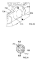
crank shaft 114 is afly wheel 702 which contains a number ofmetal fins 704 which form an impeller. As thefly wheel 702 rotates, the impeller blows air around the out side of the engine. Adjacent theimpeller 702 are twogenerators 706; 708. The two generators generate electricity using magnets and the change of inductance caused by therotating flywheel 702. As thefly wheel 702 rotates, it causes the twogenerators 706; 708 to produce electricity. Thefirst generator 706 is used to provide electricity for the ignition system of the engine and theelectronic controller 716. Thesecond generator 708 is used to provide electricity for theoil pump 700 and thesolenoid 714 in the carburettor. Both are connected to theelectronic controller 716 viacables 717. The twogenerators 706; 708 will be off-the-shelf products. - Also mounted adjacent the flywheel are two
sensors 710; 712. Thefirst sensor 710 monitors the temperature of the engine block and sends a signal via anelectric cable 711 indicative of the temperature to theelectronic controller 716. Thesecond sensor 712 monitors the angular position of theflywheel 702 and sends a signal via anelectric cable 713 indicative of the angular position of theflywheel 702 back to theelectronic controller 716. This signal can also be used by theelectronic controller 716 to determine the rate of rotation of thefly wheel 702, as well as its angular position. - The
oil pump 700 is an electricallypowered oil pump 700, the power for which is supplied by theelectronic controller 716 viaelectric cable 715. The oil pump is shown inFigure 4 . This type of oil pump is described inEP1236894 and therefore further explanation of its construction will not be described in detail. Theoil pump 700 is driven by theelectronic controller 716 which sends a square shapedvoltage signal 892 to the oil pump (seeFigure 14A ) When the voltage is at V1, it causes thepiston 850 of the pump to move, reducing the size of theoil chamber 852. This causes a preset amount of oil to be pump out of thechamber 852. When voltage is "0", the piston returns to its starting position due to thespring 854, enlargening thechamber 852 and allowing thechamber 852 to fill with oil. The higher the frequency of the square shapedvoltage signal 892, the more oil theoil pump 700 pumps per unit of time. The oil pump is capable of running at two speeds (the first speed shown inFigure 14A , the second speed being shown inFigure 14B where the frequency of the square shapedvolge signal 892, and hence the movement of thepiston 850, is double) and its general operation is described in more detail below. - The
spark plug 730 is connected to theelectronic controller 716 via acable 732. Ignition of the spark plug is controlled by theelectronic controller 716. - A
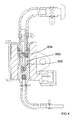
primer 734 is mounted on therear wall 736 of thehousing 800 of the power cutter. The primer is a manual pump. Apipe 738 connects from thepetrol tank 124 to theprimer 734. Asecond pipe 740 connects from the primer to thecarburettor 126. A brief description of the principle of how the primer works will now be described with reference toFigure 5 . The primer consists of twovalves 742; 744 located in series which allow the petrol to flow one way through them only (indicated by Arrows A and B). Located between the twovalves 742; 744 is achamber 750 having arubber dome 746 forming a wall which is accessible to the user of the power cutter. Onevalve 742 only allowing petrol to enter thechamber 750, the other only allowing petrol to leave thechamber 750. In order to use the primer, the operator, compresses the rubber dome 746 (shown as dashed lines 748). This reduces the amount of volume in thechamber 750 formed between the valves and hence the amount of space which can contain petrol. As such, petrol is ejected from the primer through the one of thevalves 744, as thesecond valve 742 remains closed, preventing petrol from leaving thechamber 750 via thatvalve 742. When the operator releases thedome 746, the volume of thechamber 750 increases, causing petrol to be sucked into thechamber 750 through thesecond valve 742 as the first valve remains closed 744 preventing petrol from entering thechamber 750 through thatvalve 744. Repetitive compressing and releasing of thedome 746 results in the petrol being pumped through theprimer 734. The primer is arranged so that the operator can manually pump the petrol from thetank 124 to thecarburettor 126 through thepipes 738; 740. - The purpose of the primer is to enable the operator to place petrol into the carburettor. Otherwise the operator has to spin the engine a number of times using the pull cord before a sufficient amount of petrol is sucked through into the
carburettor 126. - A
DECO valve 752 is mounted on the side of thecylinder 120. Thevalve 752 is opened manually by the operator prior to starting the engine. When opened, the DECO valve reduces the pressure within thecylinder 120 prior to ignition. This enables the starting of the engine using the pull cord to be made easier as the amount compression of the petrol/air mixture required is reduced. When the engine is started, the DECO valve automatically closes. - The
electronic controller 716 has an on/offswitch 754 in the form of arotatable knob 758. The switch is connected to the electronic controller via anelectric cable 756. - The
knob 758 as apointer 764 integrally formed on its periphery. Therotatable knob 758 has two angular positions between which it can rotate. In the first position, the switch is ON. In this position, thepointer 764 points to an ON label 762 (seeFigure 1 ). In the second position, the switch is OFF. In this position, thepointer 764 points to anOFF label 760. When the rotatable knob is in the ON position, the operator can start the engine and use the power cutter. When therotatable knob 758 is in the OFF position, the engine is prevented from being started. If therotatable knob 758 is moved from the ON to the OFF position when the engine is running, the engine is automatically switched off. - A
safety button 766 is located in the centre of theknob 758. If the engine is running (ie the knob is in the ON position), depression of thesafety button 766 will result in the engine being switched off. Theknob 758 then automatically returns to the OFF position. If theknob 758 is prevented from returning to the OFF position after the safety button has been depressed, the engine will not be able to be started until theknob 758 has been allowed to return to the OFF position. - The construction of the assembly for the ON/
OFF switch 754, which includes theknob 758 andsafety button 766, will now be described. - The ON/OFF switch assembly consists of the
rotatable knob 758, acrank 768, aswitch cam 770 and thesafety button 766. - The
crank 768 is rigidly fixed into therear wall 736 of thehousing 800 and prevented from rotation. Thecrank 768 comprises asocket 772 into which is rigidly mounted a micro switch 774 (seeFig 8C ). - Rotatably mounted on the outside of the
crank 768 is theknob 758. Rotatably mounted on the inside of thecrank 768 is theswitch cam 770. Abolt 778, which passes through the base of atubular recess 776 formed in theknob 758, screws into theswitch cam 770 and is rigidly attached to it. Sandwiched between the head of thebolt 778 and the base of therecess 776 is aspring 780. Thebolt 778 andspring 780 hold theknob 758 andswitch cam 770 onto thecrank 768, biasing them towards each other as the spring biases the head of thebolt 778 away from the base of therecess 776. The knob can rotate through a limited range of movement (between the ON and OFF positions) relative to thecrank 768. The range of positions is limited bypegs 786 formed on the underside of the knob engaging withrecesses 788 formed in the edge of therear wall 736 of the housing. Theswitch cam 770 can also rotate through a limited range of movement relative to thecrank 768. In addition, theswitch cam 770 can axially slide relative to the crank 768 in a direction parallel to the longitudinal axis of thebolt 778 over a limited range of movement, the range being limited by the length of thebolt 778 within therecess 776. Thebolt 778 rotates and slides with theswitch cam 770. - The
safety button 766 is mounted within thetubular recess 776 formed in theknob 758 and encloses the end of thebolt 778 located in the recess776 and the spring 780 (seeFig 9 ). Thesafety button 766 can axially slide within therecess 776 towards or away from theswitch cam 770. The range of outward axial movement of the safety button is limited bystops 782 each engaging with an inner step of theknob 758. The head of thebolt 778 directly abuts the underside of thesafety button 766. Depression of the safety button, causes thebolt 778 to be pushed through the base, compressing thespring 780, moving theswitch cam 770 away from the crank768 andknob 758. - Connected between the
knob 758 and thecrank 768 is a longhelical spring 784. Thehelical spring 784 locates in acircular channel 790 formed on the underside of theknob 758 as best seen inFigure 10 . One end abuts against awall 792 at the end of thechannel 790. The other end abuts against a stop (not shown) formed on thecrank 772. Thespring 784 rotationally biases theknob 758 relative to the crank to its OFF position. - Connected between the
switch cam 770 and thecrank 768 is aleaf spring 794 as best seen inFigures 12 and 13 . One end of theleaf spring 794 is connected using asmall bolt 796 to theswitch cam 770. The other end abuts astop 798 on thecrank 768. Theleaf spring 794 rotationally biases theswitch cam 770 relative to the crank to an OFF position. - Formed on the underside of the
knob 758 are tworamps 820, each ramp having aramp end 822 as best seen inFigure 10 . Formed on the side of theswitch cam 770 which faces theknob 758 areramp recesses 824 which have ramp recess ends 826 as best seen inFigure 9 . When the switch assembly is in the OFF position ie when both theknob 758 and theswitch cam 770 in their OFF positions under the biasing force of theirrespective springs 784; 794, each of the tworamps 820 is located in acorresponding ramp recess 824 with the ramp ends 822 of eachramp 820 abutting directly against the ramp recess ends 826 of thecorresponding ramp recess 824. - Formed on the underside of the
crank 768 are twocrank ramps 828, eachramp 828 having a crankramp end 830 as best seen inFigure 8C . Formed on the side of theswitch cam 770 which faces theknob 758 are switch cam crankramps 832 which have switch cam crank ramp ends 834 as best seen inFigure 9 . When the switch assembly is in the OFF position ie with both the knob and theswitch cam 770 in their OFF positions under the biasing force of theirrespective springs 784; 794, each of the two switch cam crankramps 832 are located against the low end (the end of thecrank ramp 828 away from the crank ramp end 830) of the corresponding crankramp 828 as shown inFig 8C . - Formed around the edge of the
switch cam 770 is aperipheral cam 836 as best seen inFigures 8A and 8B . Themicro switch 774 comprises apin 838 which projects from the body of themicro switch 774. Thepin 838 is capable of sliding axially in or out of the body of themicro switch 774 and biased to its outer most position by a spring (not shown) inside themicro switch 774. Thepin 838 engages theperipheral cam 836. Rotation of theswitch cam 770 causes thepin 838 to slide along theperipheral cam 836, which causes it to be pushed into the body of themicro switch 774 against the biasing force of the spring, or allows it to slide out of the body of themicro switch 774 under influence of the spring. When theswitch cam 770 is in its OFF position, the pin is pushed into the body of themicro switch 774 as shown inFigure 8A . When switch cam is rotated to its ON position, thepin 838 extends to its outer most position as shown inFigure 8B . - The way the assembly for the ON/OFF switch works will now be described.
- Initially, the
knob 758 and theswitch cam 770 are both located in their OFF positions. The operator of the power cutter desires to turn the unit on using the ON/OFF switch. The operator uses their hand to rotate theknob 758 from its OFF position to its ON position. When theknob 758 is rotated, it causes thecam switch 770 to rotate in unison as the rotary movement is transferred from theknob 758 to switchcam 770 by the ramp ends 822 of eachramp 820 pushing the ramp recess ends 826 of eachcorresponding ramp recess 824, against which it abuts, in the direction of Arrow M inFigure 9 , to cause theswitch cam 770 to rotate with theknob 758. As theswitch cam 770 rotates, the two switch cam crankramps 832, which are initially located against the low end of the crank ramps 828 (shown inFigure 8C ), ride up the crank ramps 828 (shown inFigure 8D ), which are stationary. As the switch cam crankramps 832 ride up the crank ramps 828 due to the rotation of theswitch cam 770, theswitch cam 770 is forced to axially slide away from the knob 758 (direction of Arrow N inFigure 9 ), causing thespring 780 to be compressed and the head of thebolt 778 to move towards the base of therecess 776. When the switch cam has rotated sufficiently that the crank ramp ends 830 and the switch cam crank ramp ends 834 become aligned, theswitch cam 770 axially slides under the biasing force of thespring 780 towards theknob 758, ensuring that thecrank ramp end 830 and the switch cam crank ramp ends 834 abut against each other as shown inFigure 8E . When the crank ramp endS 830 and the switch cam crank ramp ends 834 abut each other as shown inFigure 8E , theswitch cam 770 is in its ON position and is prevented from returning to its OFF position, under the influence of theleaf spring 794, as the crank ramp endS 830 and the switch cam crank ramp ends 834 prevent relative movement as they are jammed against each other. Theknob 758 is prevented from returning to its OFF position under the influence of thespring 784 by theramps 820 being held within the ramp recesses 824 by the action of thespring 780 which overrides thespring 784. When theswitch cam 770 rotates from the OFF position (seeFigure 8A ) to the ON position (Figure 8B ), theperipheral cam 836 rotates, which in turn allows thepin 838 to extend from the body of themicro switch 774. This in turn makes a connection which allows theelectric controller 716 to activate the power cutter and allow it to start when the pull cord is pulled. - As such, the assembly of the ON/OFF switch is now ON with the
knob 758 and theswitch cam 770 both in their ON positions, allowing thepin 838 to extend from the body of themicro switch 774. There are two way of switching the ON/OFF switch assembly to its OFF position. - The first method comprises the depression of the
safety button 766. Depression of thesafety button 766 causes the head of thebolt 778 to slide towards the base of therecess 776 of theknob 758, compressing thespring 780, which in turn causes theswitch cam 770 to axially slide away from theknob 758. As theswitch cam 770 axially slides, theswitch cam 770 moves away from thecrank 768, which in turn causes the crank ramps 828 and the switch cam crankramps 832 to move away from each other, and thus causes the crank ramp ends 830 and the switch cam crank ramp ends 834 to disengage. As such, theswitch cam 770 can now rotate back to its OFF position under the influence of theleaf spring 794. As the knob is held in its ON position by theramps 820 being held within the ramp recesses 824, the knob 858 will also return to its OFF position as the ramp recesses 824 rotate with theswitch cam 770. Should theramps 820 become disengaged from the ramp recesses 824 due to the sliding movement of theswitch cam 770 relative to theknob 758, theknob 758 will return to its OFF position under the influence of thespring 784 between theknob 758 and thecrank 768. - The second method of switching the ON/OFF switch assembly OFF comprises the rotation of the
knob 758. The operator rotates theknob 758 to its OFF position. As theramps 820 are held within the ramp recesses 824, rotation of theknob 758 urges rotation of theswitch cam 770. However, theswitch cam 770 is prevented from rotating as the crank ramp ends 830 and the switch cam crank ramp ends 834 abut each other. Therefore, theramps 820 slide out of the ramp recesses 824, the ramp ends 822 moving away from ramp recess ends 826. As theramps 820 slide out of the ramp recesses 824, theswitch cam 770, which is prevented from rotating, axially slides away from the knob 858 by the caming action of theramps 820 and ramp recesses 824. When theswitch cam 770 has slid sufficiently far enough away from theknob 758, the crank ramp ends 830 and the switch cam crank ramp ends 834, which are sliding away from each other, become disengaged. Thus theswitch cam 770 can rotate under the influence of theleaf spring 794 to its OFF position. Theknob 758 will move under the influence of the operator and/or thespring 784. As such, both theknob 758 and theswitch cam 770 return to their OFF position where they are held by thesprings 784; 794. - When both the knob and
switch cam 770 moved to their OFF positions, theramps 820 engage with the ramp recesses 824 so that the switch can be used again to switch on the power cutter. - The operation of the power cutter will now be described.
- The operator first activates the
DECO valve 752 and then pumps some petrol into thecarburettor 126 using theprimer 734. The operator then switches the ON/OFF switch to ON by rotation of theknob 758 to its ON position. The operator then pulls the pull cord to rotate the crank 114 of the engine. As thecrank 114 rotates, thefly wheel 702 also rotates causing the twogenerators 706; 708 to produce sufficient electricity to operate the power cutter. - The electronic controller checks the temperature of the
engine using sensor 710. If the engine is cold, it uses the electricity from thesecond generator 708 to power thesolenoid 714 in the carburettor to set the "automatic choke". Thesecond generator 708 is not powerful enough to power both theoil pump 700 andsolenoid 714 at the same time. Therefore, when theelectronic controller 716 is operating thesolenoid 714, it switches off theoil pump 700. It has been found that the period during which lubricating oil is not required before the engine is damaged is greater than that required to heat up the engine. - The electronic controller supplies the power to the spark plug to cause combustion in the engine, the power being provided by the
first generator 706, the timing being determine by theelectronic controller 716 based on the signal provided by thesensor 712 in relation to the angular position of thefly wheel 702. - Once the engine commences firing, the DECO valve automatically closes. The
electronic controller 716 continues to monitor the engine temperature and when it has reached a predetermine temperature, theelectronic controller 716 switches thesolenoid 714 in thecarburettor 126 off. Theelectronic controller 716 then commences supplying a square shape voltage signal to the oil pump to commence pumping oil. The electronic controller monitors the speed of the engine using the signal provided by thesensor 712 monitoring the angular position of thefly wheel 702 to calculate the rotational speed. If the rotational speed is below a predetermined value, theelectronic controller 716 sends a signal (Figure 14A ) to theoil pump 700 to cause it to pump at a slow speed.. If the rotational speed is above a predetermined value, theelectronic controller 716 sends a signal (Figure 14B ) to theoil pump 700 to cause it to pump at a higher speed. The speed of the engine is dependent on the operator squeezing a trigger switch which connects to the carburettor via a cable. - Whilst the engine is running the
electronic controller 716 monitors the oil being added to the petrol/air mixture using thesensor 140. If thesensor 140 detects that the rate of flow of the oil being pumped by theoil pump 700 has dropped below a predetermine amount (eg there is a blockage in the oil pipe142 or thetank 128 is empty), the electronic controller places the engine into an idle mode using the ignition system so that the engine runs, but at a minimal rate. The operator can not speed up the engine using the trigger until thesensor 140 detects the flow of oil. This protects the engine from damage due to a lack of lubrication. It has been found that the engine can run in idle mode for a considerable period of time before damage to the engine results. - In order for the operator to stop the power cutter, the operator either depresses the
safety button 766 or rotates theknob 758 to its OFF position. - An embodiment of an ON/OFF switch according to the present invention will now be described with reference to
Figures 15 to 24 . The embodiment provides an alternative design of ON/OFF switch to the example described above and which can be substituted for that design in a power cutter as described above. - Where the same features in this embodiment are the same as those disclosed in the previous example of the ON/OFF switch described above, the same reference numbers have been used.
- Except for the design of the ON/
OFF switch 754, the design of the rest of the power cutter is that same as that described above with reference toFigure 1 to 14 . - The
switch 754 comprises arotatable knob 758. Theknob 758 has apointer 764 integrally formed on its periphery. Therotatable knob 758 has two angular positions between which it can rotate. In the first position, the switch is ON. In this position, thepointer 764 points to an ON label 762 (seeFigure 19A ). In the second position, the switch is OFF. In this position, thepointer 764 points to an OFF label 760 (seeFigure 17A ). When the rotatable knob is in the ON position, the operator can start the engine and use the power cutter. When therotatable knob 758 is in the OFF position, the engine is prevented from being started. If therotatable knob 758 is moved from the ON to the OFF position when the engine is running, the engine is automatically switched off. - A
safety button 766 is located in the centre of theknob 758. If the engine is running (ie the knob is in the ON position), depression of thesafety button 766 will result in the engine being switched off. - A
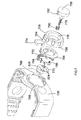
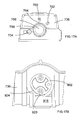
circular hole 900 is formed through therear wall 736 of thehousing 800. Therotatable knob 758 is mounted onto the outside of therear wall 736 adjacent thecircular hole 900. Acam wheel 902 is rotatably mounted on the inside of therear wall 736 adjacent thecircular hole 900. Two screws (not shown) connect therotatable knob 758 to thecam wheel 902, the screws passing through thecircular hole 900. The peripheries of therotatable knob 758 and thecam wheel 902 sandwich the periphery of thecircular hole 900 to hold therotatable knob 758 and thecam wheel 902 in place on the rear wall over thecircular hole 900. Therotatable knob 758 and thecam wheel 902 can rotate about the central axis of the circular hole, therotatable knob 758 and thecam wheel 902 rotating in unison. - Formed on the part of the
rear wall 736 sandwiched between therotatable knob 758 and thecam wheel 902 is a curved rib 904 (seeFigure 16 ). Formed on the rear of therotatable knob 758 is a correspondingly shaped groove 906 (seeFigure 20 ). When therotatable knob 758 is mounted on therear wall 736, therib 904 locates inside thegroove 906. The length of thegroove 906 is longer than therib 904 allowing therib 904 to slide within the groove. This restricts the amount of pivotal movement of the knob, and hence thecam wheel 902, to sixty degrees, allowing thepointer 764 to pivot between its angular positions between its ON and OFF positions. - Also formed on the rear of the
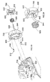
rotatable knob 758 are twopockets pocket pins 912 and springs 914 which bias thepins 912 out of thepockets pins 912 are prevented from completely exiting thepockets springs 914. Formed on the part of therear wall 736 sandwiched between therotatable knob 758 and thecam wheel 902 are two pairs ofrecesses 916, eachrecess 916 in each pair being located on the opposite side of thecircular hole 900 to the other recess in that pair. The location of each pair ofrecesses 916 corresponds to an angular position of theknob 758. When theknob 758 is rotated to one of its angular positions, thepins 912 locate within therecesses 916 of the first corresponding pair, due tor the biasing force of thesprings 914, to latch theknob 758 in that angular position and hold it there. When theknob 758 is rotated, thepins 912 ride out of therecesses 916 by being pushed into thepockets 910. As theknob 758 rotates, thepins 912 remain in thepockets 910. When theknob 758 moves to its second angular position, the other pair ofrecesses 916 align with thepins 912, which then move out of thepockets 910 and enter therecesses 916 under the biasing force of thesprings 914. The knob is then latched in its second angular position. - Mounted with a
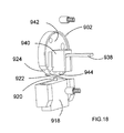
bracket 926 on the inside of therear wall 736, adjacent thecam wheel 902 is a micro switch 918 (seeFigure 17B ). Themicro switch 918 comprises apin 920 which projects from the body of themicro switch 918. Thepin 920 is capable of sliding axially in or out of the body of themicro switch 920 and biased to its outer most position by a spring (not shown) inside themicro switch 920. Alever 922 is pivotally attached to themicro switch 918. Thelever 922 lies across the end of thepin 920. Pivotal movement of thelever 922 towards themicro switch 918, pushes thepin 920 into themicro switch 918. - Formed around the edge of the
cam wheel 902 is aperipheral cam 924 as best seen inFigure 17B . Theperipheral cam 924 engages with thelever 922. Rotation of thecam wheel 902 causes thelever 922 to slide along theperipheral cam 924, which causes it to be pivoted towards the body of themicro switch 918, which in turn pushes thepin 920 into themicro switch 918, against the biasing force of the spring, or to be pivoted away from the body of themicro switch 918, due to biasing force on thepin 920, allowing thepin 920 to slide out of the body of themicro switch 918 under influence of the spring. When the cam wheel is in its OFF position (Figure 17B ), thepin 920 is pushed into the body of themicro switch 918. When thecam wheel 902 is rotated to its ON position, thepin 920 extends to its outer most position as shown inFigure 19B . - The
micro switch 918 can be switched on and off by the depression or release of thepin 920 by the rotation of theknob 758 between its two angular positions. - The
safety button 766 is mounted within atubular recess 934 formed in theknob 758 and is capable of sliding within therecess 934 towards or away from thebase 936 of therecess 934. Aspring 928 is sandwiched between thesafety button 766 and thebase 936 of the recess and biases thesafety button 766 out of therecess 934. The range of outward movement of thesafety button 766 is limited by fourstops 930 mounted onlegs 932 which engage with the underside of theknob 758 when the safety button has reached its maximum outward position. The range of inward movement of thesafety button 766 is limited by thebase 936 of therecess 934. - Attached to the underside of the
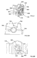
safety button 766 is aflexible tongue 938. The tongue extends through an aperture in thebase 936 of therecess 934 and then is curved by aguide 940 formed on theinner wall 942 of thewheel cam 902 through 90 degrees towards anaperture 923 formed in the peripheral cam 924 (seeFigure 23A ). As can be seen, theaperture 923 is formed at aside edge 925 of theperipheral cam 924, theperipheral cam 924 providing three sides to theaperture 923. However, it will appreciated that theaperture 923 can be formed in the middle of theperipheral cam 924 as shown inFigure 23 B . Alternatively, theend 944 of the tongue can pass along side of theperipheral cam 924 as shown inFigure 23C , thus avoiding the need to form an aperture in theperipheral cam 924. When thesafety button 766 is located in its most outward position, theend 944 of thetongue 938 is located just inside of theguide 940 adjacent theaperture 923 in theperipheral cam 924. When thesafety button 766 is located in its most inward position, theend 944 of thetongue 938 passes through and projects from theaperture 923 in theperipheral cam 924. Depression of thesafety button 766 causes theend 944 of thetongue 738 to exit theaperture 923 in theperipheral cam 924. - When the
knob 758 is in its ON position as shown inFigure 19A , theaperture 923 in theperipheral cam 924 faces thelever 922. When theknob 758 is in its ON position, theperipheral cam 924 allows thelever 922 to pivot away from themicro switch 918, in turn allowing thepin 920 to slide out of the micro switch (seeFigure 19B ). Thesafety button 766 is biased towards its outward position by thespring 928. As such, theend 944 of thetongue 938 is located within thecam wheel 902. However, when the safety button is pushed into the recess, theend 944 of the tongue is pushed through the aperture in theperipheral cam 924, away from thecam wheel 902, into engagement with thelever 922. As theend 944 of the tongue continues to move away from thecam wheel 902, it pivots thelever 922 toward the micro switch, pushing thepin 920 on themicro switch 918 into the micro switch. When theknob 758 is in its OFF position as shown inFigure 17A , the aperture in theperipheral cam 924 is located away from thelever 922 and therefore depression of safety button has no effect on the lever as the end of the tongue can not engage it. - Initially, the ON/OFF switch is in its OFF position, with the
rotatable knob 758 in its first angular position and thepointer 764 pointing to theOFF label 760. Theperipheral cam 924 on thecam wheel 902, is located in a position where it pushes thepivotal lever 922 towards themicro switch 918 which in turn pushed thepin 920 into the micro switch (seeFigure 17A ). When the pin is in this position, it provides a signal to theelectric controller 716, when an electrical power supply is provided to themicro switch 918 andelectric controller 716 by the operation of the pull cord of the power cutter that the engine can not be started. In order for the power cutter to be started, therotatable knob 758 is rotated to its first angular position, thepointer 764 pointing to theON label 762 to put the ON/OFF switch in its ON position. As therotatable knob 758 rotates, thecam wheel 902, and hence theperipheral cam 924 also rotate in unison. Theperipheral cam 924 rotates to a position where it allows thepivotal lever 922 to pivot away from themicro switch 918 which in turn allows thepin 920 to extend from the micro switch (seeFigure 19B ). When thepin 920 is in this position, it provides a signal to theelectric controller 716, when an electrical power supply is provided to themicro switch 918 andelectric controller 716 by the operation of the pull cord of the power cutter, that the engine can be started. Whilst the engine is running, thepin 920 must remain extended from themicro switch 918. In order to switch the power cutter off, thepin 920 of the micro switch must be pushed into themicro switch 918. This is achieved in one of two ways. Firstly, therotatable knob 758 can be rotated to its OFF position. Rotation of theknob 758 results in rotation of the cam wheel andperipheral can 924, causing theperipheral cam 924 to push thelever 922 towards themicro switch 918 and hence the pin into themicro switch 918. Secondly, thesafety button 766 can be pushed into therecess 934, causing theend 944 of thetongue 938 to project out of theaperture 923 inperipheral cam 924 and into engagement with thelever 922, causing it pivot towards themicro switch 918 hence pushing the pin into themicro switch 918. When thepin 920 is pushed inside of themicro switch 918, it provides a signal to theelectric controller 716 that the engine should be stopped. If the engine is stopped by depression of thesafety button 766, release of the safety button will allow to return to its outer most position under the biasing force of thespring 928. When this happens theend 944 of thetongue 938 is retracted through the aperture in theperipheral cam 924 inside of thecam wheel 902 allowing thelever 922 to pivot away from the micro switch and hence thepin 920 to slide out of the micro switch 91. - The operation of the power cutter is the same for this embodiment of ON/OFF switch as for the previous example of ON/OFF switch.
- It will be appreciated by a person skilled in the art that an additional safety feature could be added whereby, when the engine has been stopped by depression of the
safety button 766, therotatable knob 758 has to be first rotated to its OFF position and then back to its ON position before the engine can be started again. -
Figure 24 shows an alternative design ofsafety button 766 where thetongue 938 is integrally formed with thebutton 766.
Claims (14)
- A switch mechanism comprising a support structure 736;
an electric switch 918 mounted on the support structure and which comprises an activator 920 moveable between a first position where the electric switch is switched on and a second position where the electric switch is switched off;
a first actuator 758 moveably mounted on the support structure;
a cam 924, having a cam surface, connected to the first actuator so that movement of the first actuator results in movement of the cam;
a second actuator 766 moveably mounted on the support structure;
a bar 938 connected to the second actuator so that movement of the second actuator results in movement of the bar;
wherein the cam 924 is capable of engaging with the activator so that movement of the cam by movement of the first actuator results in the activator moving between its two positions;
wherein the bar is capable of engaging with the activator so that movement of the bar by movement of the second actuator results in the activator moving between its two positions;
wherein the bar passes through or alongside the surface of the cam when it engages the activator. - A switch mechanism as claimed in claim 1 wherein the first actuator 758 comprises a recess in which is located the second actuator 766 which is a slideable button and which is capable of being linearly slid within the recess between a first position and a second position, the second actuator being biased towards its first position.
- A switch mechanism as claimed in claim 2 wherein movement of the first actuator, when the second actuator is in its first position, moves the activator between its first and second positions; and
wherein movement of the second actuator 766 from its first position to its second position, when the activator 920 is in its first position, moves the activator 920 to its second position . - A switch mechanism as claimed in any one of the previous claims wherein the first actuator 758 is capable of moving between two positions to move the activator between its two positions, the first actuator being capable of being latched in either of the positions.
- A switch mechanism as claimed in any one of the previous claims wherein the first actuator is a rotatable knob capable of rotation about an axis of rotation.
- A switch mechanism as claimed in claims 5 wherein the cam is directly mounted on the rotatable knob so that rotation of the knob about its axis of rotation results in rotation of the cam about the axis of rotation of the knob.
- A switch mechanism as claimed in any one of the previous claims wherein the bar is elongate nand slides linearly.
- A switch mechanism as claimed in any one of the previous claims wherein the end 944 of the bar engages the activator 920.
- A switch mechanism as claimed in any one of the previous claims wherein the bar is a flexible tongue.
- A switch mechanism as claimed in claim 9 wherein the flexible tongue curves through 90 degrees along its length.
- A switch mechanism as claimed in any one of the previous claims wherein the activator comprises a slideable pin which is capable of engaging the surface of the cam or the bar.
- A switch mechanism as claimed in claim 12 wherein the slideable pin is capable of sliding into or out of electric switch.
- A switch mechanism as claimed in either of claims 11 or 12 wherein the activator further comprises a pivotal lever which locates against the slideable pin wherein pivotal movement of the lever resulting in the sliding movement of the pin, the lever being of engaged by the surface of the cam or the bar.
- A power tool comprising a switch mechanism as claim in any one of the previous claims wherein;1) when the electric switch is on and the power tool is deactivated, the power tool is able to be activated, and;2) when the electric switch is off and the power tool is deactivated, the power tool is prevented from being activated, and;3) when the switch from being on to being off when the power tool is activated, the power tool is deactivated.
Applications Claiming Priority (1)
| Application Number | Priority Date | Filing Date | Title |
|---|---|---|---|
| GBGB0910774.9A GB0910774D0 (en) | 2009-06-23 | 2009-06-23 | Switch mechanism for a power cutter |
Publications (2)
| Publication Number | Publication Date |
|---|---|
| EP2267743A1 true EP2267743A1 (en) | 2010-12-29 |
| EP2267743B1 EP2267743B1 (en) | 2012-05-23 |
Family
ID=40972597
Family Applications (1)
| Application Number | Title | Priority Date | Filing Date |
|---|---|---|---|
| EP10165145A Active EP2267743B1 (en) | 2009-06-23 | 2010-06-07 | Power cutter switch |
Country Status (5)
| Country | Link |
|---|---|
| US (1) | US8586886B2 (en) |
| EP (1) | EP2267743B1 (en) |
| JP (1) | JP5539795B2 (en) |
| BR (1) | BRPI1002182A2 (en) |
| GB (1) | GB0910774D0 (en) |
Cited By (2)
| Publication number | Priority date | Publication date | Assignee | Title |
|---|---|---|---|---|
| FR2974232A1 (en) * | 2011-04-18 | 2012-10-19 | Schneider Electric Ind Sas | EMERGENCY STOP DEVICE |
| RU2606668C2 (en) * | 2011-02-17 | 2017-01-10 | Андреас Штиль АГ & Ко. КГ | Working tool with manual supply |
Families Citing this family (10)
| Publication number | Priority date | Publication date | Assignee | Title |
|---|---|---|---|---|
| DE102009061741B3 (en) * | 2008-11-20 | 2021-05-06 | Yamabiko Corporation | Working device with internal combustion engine |
| DE102010055387A1 (en) * | 2010-12-21 | 2012-06-21 | Solo Kleinmotoren Gmbh | Method and device for separate lubrication of an internal combustion engine |
| JP2013151862A (en) * | 2012-01-24 | 2013-08-08 | Hitachi Koki Co Ltd | Engine working machine |
| DE102012007617B4 (en) * | 2012-04-18 | 2014-11-13 | Andreas Stihl Ag & Co. Kg | Implement with a fuel pump |
| DE102012009166A1 (en) * | 2012-05-03 | 2013-11-07 | Stanzwerk Wetter Sichelschmidt Gmbh & Co. Kg | Built-in hand control for controlling the electromotive adjustment of a sitting or lying furniture |
| JP2014073566A (en) * | 2012-10-05 | 2014-04-24 | Makita Corp | Power tool |
| US9476370B2 (en) | 2014-02-20 | 2016-10-25 | Generac Power Systems, Inc. | Single point engine control interface |
| USD743914S1 (en) * | 2014-03-13 | 2015-11-24 | Cree, Inc. | Photocontrol receptacle for lighting fixture |
| USD750314S1 (en) * | 2014-12-22 | 2016-02-23 | Cree, Inc. | Photocontrol receptacle for lighting fixture |
| US10451019B2 (en) * | 2015-07-09 | 2019-10-22 | Caterpillar Inc. | Starter device for a prime mover |
Citations (6)
| Publication number | Priority date | Publication date | Assignee | Title |
|---|---|---|---|---|
| US2948792A (en) * | 1958-09-15 | 1960-08-09 | Gen Motors Corp | Circuit controller |
| US3170995A (en) * | 1961-05-23 | 1965-02-23 | Westinghouse Electric Corp | Control switch actuating means |
| GB2232913A (en) | 1989-05-20 | 1991-01-02 | Stihl Maschf Andreas | A portable hand-guided tool |
| EP1236894A1 (en) | 2001-03-01 | 2002-09-04 | Dell'orto S.P.A. | Electromagnetically operated pump |
| WO2005056225A1 (en) | 2003-12-09 | 2005-06-23 | Aktiebolaget Electrolux | Portable working machine |
| US7264230B2 (en) | 2005-01-11 | 2007-09-04 | Walbro Engine Management, L.L.C. | Carburetor and solenoid assemblies and methods of assembling the same |
Family Cites Families (8)
| Publication number | Priority date | Publication date | Assignee | Title |
|---|---|---|---|---|
| JP2556126Y2 (en) * | 1991-09-13 | 1997-12-03 | 旭光学工業株式会社 | Camera operation parts |
| JP3750901B2 (en) * | 1999-08-31 | 2006-03-01 | 矢崎総業株式会社 | Lever switch |
| JP2002150887A (en) * | 2000-11-06 | 2002-05-24 | Omron Corp | Switch mechanism having two or more operation function, and control equipment of electric device equipped with this switch mechanism |
| US6958455B1 (en) * | 2004-09-16 | 2005-10-25 | Defond Components Limited | Lock-on/lock-off tool switch |
| US7439458B2 (en) * | 2006-08-25 | 2008-10-21 | Delphi Technologies, Inc. | Five-way directional push button on a rotary knob |
| US7920075B2 (en) * | 2006-12-21 | 2011-04-05 | Dexin Corporation | Regulation control device with an encoder and its encoder mechanism |
| JP2009070684A (en) * | 2007-09-13 | 2009-04-02 | Alps Electric Co Ltd | Compound operation type electric component |
| GB0812274D0 (en) * | 2008-07-04 | 2008-08-13 | Black & Decker Inc | Switch mechanism for a power cutter |
-
2009
- 2009-06-23 GB GBGB0910774.9A patent/GB0910774D0/en not_active Ceased
-
2010
- 2010-06-07 EP EP10165145A patent/EP2267743B1/en active Active
- 2010-06-22 JP JP2010142006A patent/JP5539795B2/en not_active Expired - Fee Related
- 2010-06-22 BR BRPI1002182-5A patent/BRPI1002182A2/en not_active Application Discontinuation
- 2010-06-22 US US12/820,677 patent/US8586886B2/en active Active
Patent Citations (6)
| Publication number | Priority date | Publication date | Assignee | Title |
|---|---|---|---|---|
| US2948792A (en) * | 1958-09-15 | 1960-08-09 | Gen Motors Corp | Circuit controller |
| US3170995A (en) * | 1961-05-23 | 1965-02-23 | Westinghouse Electric Corp | Control switch actuating means |
| GB2232913A (en) | 1989-05-20 | 1991-01-02 | Stihl Maschf Andreas | A portable hand-guided tool |
| EP1236894A1 (en) | 2001-03-01 | 2002-09-04 | Dell'orto S.P.A. | Electromagnetically operated pump |
| WO2005056225A1 (en) | 2003-12-09 | 2005-06-23 | Aktiebolaget Electrolux | Portable working machine |
| US7264230B2 (en) | 2005-01-11 | 2007-09-04 | Walbro Engine Management, L.L.C. | Carburetor and solenoid assemblies and methods of assembling the same |
Cited By (5)
| Publication number | Priority date | Publication date | Assignee | Title |
|---|---|---|---|---|
| RU2606668C2 (en) * | 2011-02-17 | 2017-01-10 | Андреас Штиль АГ & Ко. КГ | Working tool with manual supply |
| FR2974232A1 (en) * | 2011-04-18 | 2012-10-19 | Schneider Electric Ind Sas | EMERGENCY STOP DEVICE |
| WO2012143191A1 (en) | 2011-04-18 | 2012-10-26 | Schneider Electric Industries Sas | Emergency stopping device |
| RU2549184C1 (en) * | 2011-04-18 | 2015-04-20 | Шнейдер Электрик Эндюстри Сас | Emergent interrupter |
| US9147532B2 (en) | 2011-04-18 | 2015-09-29 | Schneider Electric Industries Sas | Emergency stopping device |
Also Published As
| Publication number | Publication date |
|---|---|
| EP2267743B1 (en) | 2012-05-23 |
| US20100323592A1 (en) | 2010-12-23 |
| JP2011005628A (en) | 2011-01-13 |
| GB0910774D0 (en) | 2009-08-05 |
| US8586886B2 (en) | 2013-11-19 |
| JP5539795B2 (en) | 2014-07-02 |
| BRPI1002182A2 (en) | 2012-03-27 |
Similar Documents
| Publication | Publication Date | Title |
|---|---|---|
| EP2267743B1 (en) | Power cutter switch | |
| US8168907B2 (en) | Switch mechanism for a power cutter | |
| EP2160508B1 (en) | Power cutter | |
| US7886706B2 (en) | Engine starting system | |
| US6755336B2 (en) | Return mechanism for a cyclic tool | |
| TW550149B (en) | Single push button reverse valve system for a pneumatic tool | |
| JP2007098568A (en) | Driving-in device activated by combustion power | |
| EP2572098B1 (en) | Engine and engine operating machine including the same | |
| EP0692628A1 (en) | Control system for power tool with internal combustion engine | |
| US9217410B2 (en) | Single point engine control interface | |
| US20050022391A1 (en) | Trimmer starter and method | |
| GB2187664A (en) | Hand-holdable drilling machine | |
| JP2013204533A (en) | Engine working machine | |
| JPH0127262B2 (en) | ||
| AU2002234087A1 (en) | Return mechanism for a cyclic tool |
Legal Events
| Date | Code | Title | Description |
|---|---|---|---|
| PUAI | Public reference made under article 153(3) epc to a published international application that has entered the european phase |
Free format text: ORIGINAL CODE: 0009012 |
|
| AK | Designated contracting states |
Kind code of ref document: A1 Designated state(s): AL AT BE BG CH CY CZ DE DK EE ES FI FR GB GR HR HU IE IS IT LI LT LU LV MC MK MT NL NO PL PT RO SE SI SK SM TR |
|
| AX | Request for extension of the european patent |
Extension state: BA ME RS |
|
| 17P | Request for examination filed |
Effective date: 20110627 |
|
| GRAP | Despatch of communication of intention to grant a patent |
Free format text: ORIGINAL CODE: EPIDOSNIGR1 |
|
| RIC1 | Information provided on ipc code assigned before grant |
Ipc: B23D 45/16 20060101ALI20120201BHEP Ipc: H01H 3/42 20060101ALN20120201BHEP Ipc: H01H 25/06 20060101AFI20120201BHEP |
|
| RIC1 | Information provided on ipc code assigned before grant |
Ipc: H01H 25/06 20060101AFI20120206BHEP Ipc: B23D 45/16 20060101ALI20120206BHEP Ipc: H01H 3/42 20060101ALN20120206BHEP |
|
| GRAS | Grant fee paid |
Free format text: ORIGINAL CODE: EPIDOSNIGR3 |
|
| GRAA | (expected) grant |
Free format text: ORIGINAL CODE: 0009210 |
|
| AK | Designated contracting states |
Kind code of ref document: B1 Designated state(s): AL AT BE BG CH CY CZ DE DK EE ES FI FR GB GR HR HU IE IS IT LI LT LU LV MC MK MT NL NO PL PT RO SE SI SK SM TR |
|
| REG | Reference to a national code |
Ref country code: GB Ref legal event code: FG4D |
|
| REG | Reference to a national code |
Ref country code: CH Ref legal event code: EP |
|
| REG | Reference to a national code |
Ref country code: AT Ref legal event code: REF Ref document number: 559414 Country of ref document: AT Kind code of ref document: T Effective date: 20120615 |
|
| REG | Reference to a national code |
Ref country code: IE Ref legal event code: FG4D |
|
| REG | Reference to a national code |
Ref country code: SE Ref legal event code: TRGR |
|
| REG | Reference to a national code |
Ref country code: DE Ref legal event code: R096 Ref document number: 602010001627 Country of ref document: DE Effective date: 20120802 |
|
| REG | Reference to a national code |
Ref country code: NL Ref legal event code: VDEP Effective date: 20120523 |
|
| REG | Reference to a national code |
Ref country code: LT Ref legal event code: MG4D Effective date: 20120523 |
|
| PG25 | Lapsed in a contracting state [announced via postgrant information from national office to epo] |
Ref country code: LT Free format text: LAPSE BECAUSE OF FAILURE TO SUBMIT A TRANSLATION OF THE DESCRIPTION OR TO PAY THE FEE WITHIN THE PRESCRIBED TIME-LIMIT Effective date: 20120523 Ref country code: IS Free format text: LAPSE BECAUSE OF FAILURE TO SUBMIT A TRANSLATION OF THE DESCRIPTION OR TO PAY THE FEE WITHIN THE PRESCRIBED TIME-LIMIT Effective date: 20120923 Ref country code: FI Free format text: LAPSE BECAUSE OF FAILURE TO SUBMIT A TRANSLATION OF THE DESCRIPTION OR TO PAY THE FEE WITHIN THE PRESCRIBED TIME-LIMIT Effective date: 20120523 Ref country code: NO Free format text: LAPSE BECAUSE OF FAILURE TO SUBMIT A TRANSLATION OF THE DESCRIPTION OR TO PAY THE FEE WITHIN THE PRESCRIBED TIME-LIMIT Effective date: 20120823 Ref country code: CY Free format text: LAPSE BECAUSE OF FAILURE TO SUBMIT A TRANSLATION OF THE DESCRIPTION OR TO PAY THE FEE WITHIN THE PRESCRIBED TIME-LIMIT Effective date: 20120523 |
|
| REG | Reference to a national code |
Ref country code: AT Ref legal event code: MK05 Ref document number: 559414 Country of ref document: AT Kind code of ref document: T Effective date: 20120523 |
|
| PG25 | Lapsed in a contracting state [announced via postgrant information from national office to epo] |
Ref country code: PT Free format text: LAPSE BECAUSE OF FAILURE TO SUBMIT A TRANSLATION OF THE DESCRIPTION OR TO PAY THE FEE WITHIN THE PRESCRIBED TIME-LIMIT Effective date: 20120924 Ref country code: LV Free format text: LAPSE BECAUSE OF FAILURE TO SUBMIT A TRANSLATION OF THE DESCRIPTION OR TO PAY THE FEE WITHIN THE PRESCRIBED TIME-LIMIT Effective date: 20120523 Ref country code: SI Free format text: LAPSE BECAUSE OF FAILURE TO SUBMIT A TRANSLATION OF THE DESCRIPTION OR TO PAY THE FEE WITHIN THE PRESCRIBED TIME-LIMIT Effective date: 20120523 Ref country code: HR Free format text: LAPSE BECAUSE OF FAILURE TO SUBMIT A TRANSLATION OF THE DESCRIPTION OR TO PAY THE FEE WITHIN THE PRESCRIBED TIME-LIMIT Effective date: 20120523 Ref country code: GR Free format text: LAPSE BECAUSE OF FAILURE TO SUBMIT A TRANSLATION OF THE DESCRIPTION OR TO PAY THE FEE WITHIN THE PRESCRIBED TIME-LIMIT Effective date: 20120824 |
|
| PG25 | Lapsed in a contracting state [announced via postgrant information from national office to epo] |
Ref country code: BE Free format text: LAPSE BECAUSE OF FAILURE TO SUBMIT A TRANSLATION OF THE DESCRIPTION OR TO PAY THE FEE WITHIN THE PRESCRIBED TIME-LIMIT Effective date: 20120523 |
|
| PG25 | Lapsed in a contracting state [announced via postgrant information from national office to epo] |
Ref country code: AT Free format text: LAPSE BECAUSE OF FAILURE TO SUBMIT A TRANSLATION OF THE DESCRIPTION OR TO PAY THE FEE WITHIN THE PRESCRIBED TIME-LIMIT Effective date: 20120523 Ref country code: NL Free format text: LAPSE BECAUSE OF FAILURE TO SUBMIT A TRANSLATION OF THE DESCRIPTION OR TO PAY THE FEE WITHIN THE PRESCRIBED TIME-LIMIT Effective date: 20120523 Ref country code: EE Free format text: LAPSE BECAUSE OF FAILURE TO SUBMIT A TRANSLATION OF THE DESCRIPTION OR TO PAY THE FEE WITHIN THE PRESCRIBED TIME-LIMIT Effective date: 20120523 Ref country code: RO Free format text: LAPSE BECAUSE OF FAILURE TO SUBMIT A TRANSLATION OF THE DESCRIPTION OR TO PAY THE FEE WITHIN THE PRESCRIBED TIME-LIMIT Effective date: 20120523 Ref country code: DK Free format text: LAPSE BECAUSE OF FAILURE TO SUBMIT A TRANSLATION OF THE DESCRIPTION OR TO PAY THE FEE WITHIN THE PRESCRIBED TIME-LIMIT Effective date: 20120523 Ref country code: CZ Free format text: LAPSE BECAUSE OF FAILURE TO SUBMIT A TRANSLATION OF THE DESCRIPTION OR TO PAY THE FEE WITHIN THE PRESCRIBED TIME-LIMIT Effective date: 20120523 Ref country code: MC Free format text: LAPSE BECAUSE OF NON-PAYMENT OF DUE FEES Effective date: 20120630 Ref country code: SK Free format text: LAPSE BECAUSE OF FAILURE TO SUBMIT A TRANSLATION OF THE DESCRIPTION OR TO PAY THE FEE WITHIN THE PRESCRIBED TIME-LIMIT Effective date: 20120523 |
|
| PG25 | Lapsed in a contracting state [announced via postgrant information from national office to epo] |
Ref country code: PL Free format text: LAPSE BECAUSE OF FAILURE TO SUBMIT A TRANSLATION OF THE DESCRIPTION OR TO PAY THE FEE WITHIN THE PRESCRIBED TIME-LIMIT Effective date: 20120523 Ref country code: MK Free format text: LAPSE BECAUSE OF FAILURE TO SUBMIT A TRANSLATION OF THE DESCRIPTION OR TO PAY THE FEE WITHIN THE PRESCRIBED TIME-LIMIT Effective date: 20120523 |
|
| REG | Reference to a national code |
Ref country code: IE Ref legal event code: MM4A |
|
| PLBE | No opposition filed within time limit |
Free format text: ORIGINAL CODE: 0009261 |
|
| REG | Reference to a national code |
Ref country code: FR Ref legal event code: ST Effective date: 20130228 |
|
| STAA | Information on the status of an ep patent application or granted ep patent |
Free format text: STATUS: NO OPPOSITION FILED WITHIN TIME LIMIT |
|
| PG25 | Lapsed in a contracting state [announced via postgrant information from national office to epo] |
Ref country code: IE Free format text: LAPSE BECAUSE OF NON-PAYMENT OF DUE FEES Effective date: 20120607 Ref country code: ES Free format text: LAPSE BECAUSE OF FAILURE TO SUBMIT A TRANSLATION OF THE DESCRIPTION OR TO PAY THE FEE WITHIN THE PRESCRIBED TIME-LIMIT Effective date: 20120903 Ref country code: FR Free format text: LAPSE BECAUSE OF NON-PAYMENT OF DUE FEES Effective date: 20120723 |
|
| 26N | No opposition filed |
Effective date: 20130226 |
|
| REG | Reference to a national code |
Ref country code: DE Ref legal event code: R097 Ref document number: 602010001627 Country of ref document: DE Effective date: 20130226 |
|
| PG25 | Lapsed in a contracting state [announced via postgrant information from national office to epo] |
Ref country code: MT Free format text: LAPSE BECAUSE OF FAILURE TO SUBMIT A TRANSLATION OF THE DESCRIPTION OR TO PAY THE FEE WITHIN THE PRESCRIBED TIME-LIMIT Effective date: 20120523 Ref country code: BG Free format text: LAPSE BECAUSE OF FAILURE TO SUBMIT A TRANSLATION OF THE DESCRIPTION OR TO PAY THE FEE WITHIN THE PRESCRIBED TIME-LIMIT Effective date: 20120823 |
|
| PG25 | Lapsed in a contracting state [announced via postgrant information from national office to epo] |
Ref country code: AL Free format text: LAPSE BECAUSE OF FAILURE TO SUBMIT A TRANSLATION OF THE DESCRIPTION OR TO PAY THE FEE WITHIN THE PRESCRIBED TIME-LIMIT Effective date: 20120523 |
|
| PG25 | Lapsed in a contracting state [announced via postgrant information from national office to epo] |
Ref country code: TR Free format text: LAPSE BECAUSE OF FAILURE TO SUBMIT A TRANSLATION OF THE DESCRIPTION OR TO PAY THE FEE WITHIN THE PRESCRIBED TIME-LIMIT Effective date: 20120523 |
|
| PG25 | Lapsed in a contracting state [announced via postgrant information from national office to epo] |
Ref country code: LU Free format text: LAPSE BECAUSE OF NON-PAYMENT OF DUE FEES Effective date: 20120607 Ref country code: SM Free format text: LAPSE BECAUSE OF FAILURE TO SUBMIT A TRANSLATION OF THE DESCRIPTION OR TO PAY THE FEE WITHIN THE PRESCRIBED TIME-LIMIT Effective date: 20120523 |
|
| PG25 | Lapsed in a contracting state [announced via postgrant information from national office to epo] |
Ref country code: HU Free format text: LAPSE BECAUSE OF FAILURE TO SUBMIT A TRANSLATION OF THE DESCRIPTION OR TO PAY THE FEE WITHIN THE PRESCRIBED TIME-LIMIT Effective date: 20100607 |
|
| REG | Reference to a national code |
Ref country code: CH Ref legal event code: PL |
|
| PG25 | Lapsed in a contracting state [announced via postgrant information from national office to epo] |
Ref country code: LI Free format text: LAPSE BECAUSE OF NON-PAYMENT OF DUE FEES Effective date: 20140630 Ref country code: CH Free format text: LAPSE BECAUSE OF NON-PAYMENT OF DUE FEES Effective date: 20140630 |
|
| PGFP | Annual fee paid to national office [announced via postgrant information from national office to epo] |
Ref country code: IT Payment date: 20190620 Year of fee payment: 10 |
|
| PGFP | Annual fee paid to national office [announced via postgrant information from national office to epo] |
Ref country code: SE Payment date: 20190611 Year of fee payment: 10 |
|
| PG25 | Lapsed in a contracting state [announced via postgrant information from national office to epo] |
Ref country code: SE Free format text: LAPSE BECAUSE OF NON-PAYMENT OF DUE FEES Effective date: 20200608 |
|
| REG | Reference to a national code |
Ref country code: SE Ref legal event code: EUG |
|
| PG25 | Lapsed in a contracting state [announced via postgrant information from national office to epo] |
Ref country code: IT Free format text: LAPSE BECAUSE OF NON-PAYMENT OF DUE FEES Effective date: 20200607 |
|
| PGFP | Annual fee paid to national office [announced via postgrant information from national office to epo] |
Ref country code: DE Payment date: 20230412 Year of fee payment: 14 |
|
| PGFP | Annual fee paid to national office [announced via postgrant information from national office to epo] |
Ref country code: GB Payment date: 20230413 Year of fee payment: 14 |