EP2267563A1 - Machine tool workpiece inspection system - Google Patents
Machine tool workpiece inspection system Download PDFInfo
- Publication number
- EP2267563A1 EP2267563A1 EP10010261A EP10010261A EP2267563A1 EP 2267563 A1 EP2267563 A1 EP 2267563A1 EP 10010261 A EP10010261 A EP 10010261A EP 10010261 A EP10010261 A EP 10010261A EP 2267563 A1 EP2267563 A1 EP 2267563A1
- Authority
- EP
- European Patent Office
- Prior art keywords
- data
- workpiece
- measurement device
- machine
- inspection system
- Prior art date
- Legal status (The legal status is an assumption and is not a legal conclusion. Google has not performed a legal analysis and makes no representation as to the accuracy of the status listed.)
- Granted
Links
Images
Classifications
-
- G—PHYSICS
- G05—CONTROLLING; REGULATING
- G05B—CONTROL OR REGULATING SYSTEMS IN GENERAL; FUNCTIONAL ELEMENTS OF SUCH SYSTEMS; MONITORING OR TESTING ARRANGEMENTS FOR SUCH SYSTEMS OR ELEMENTS
- G05B19/00—Program-control systems
- G05B19/02—Program-control systems electric
- G05B19/18—Numerical control [NC], i.e. automatically operating machines, in particular machine tools, e.g. in a manufacturing environment, so as to execute positioning, movement or co-ordinated operations by means of program data in numerical form
- G05B19/401—Numerical control [NC], i.e. automatically operating machines, in particular machine tools, e.g. in a manufacturing environment, so as to execute positioning, movement or co-ordinated operations by means of program data in numerical form characterised by control arrangements for measuring, e.g. calibration and initialisation, measuring workpiece for machining purposes
-
- G—PHYSICS
- G01—MEASURING; TESTING
- G01B—MEASURING LENGTH, THICKNESS OR SIMILAR LINEAR DIMENSIONS; MEASURING ANGLES; MEASURING AREAS; MEASURING IRREGULARITIES OF SURFACES OR CONTOURS
- G01B21/00—Measuring arrangements or details thereof, where the measuring technique is not covered by the other groups of this subclass, unspecified or not relevant
- G01B21/02—Measuring arrangements or details thereof, where the measuring technique is not covered by the other groups of this subclass, unspecified or not relevant for measuring length, width, or thickness
- G01B21/04—Measuring arrangements or details thereof, where the measuring technique is not covered by the other groups of this subclass, unspecified or not relevant for measuring length, width, or thickness by measuring coordinates of points
- G01B21/047—Accessories, e.g. for positioning, for tool-setting, for measuring probes
-
- G—PHYSICS
- G01—MEASURING; TESTING
- G01B—MEASURING LENGTH, THICKNESS OR SIMILAR LINEAR DIMENSIONS; MEASURING ANGLES; MEASURING AREAS; MEASURING IRREGULARITIES OF SURFACES OR CONTOURS
- G01B5/00—Measuring arrangements characterised by the use of mechanical techniques
- G01B5/004—Measuring arrangements characterised by the use of mechanical techniques for measuring coordinates of points
- G01B5/008—Measuring arrangements characterised by the use of mechanical techniques for measuring coordinates of points using coordinate measuring machines
-
- G—PHYSICS
- G01—MEASURING; TESTING
- G01B—MEASURING LENGTH, THICKNESS OR SIMILAR LINEAR DIMENSIONS; MEASURING ANGLES; MEASURING AREAS; MEASURING IRREGULARITIES OF SURFACES OR CONTOURS
- G01B2210/00—Aspects not specifically covered by any group under G01B, e.g. of wheel alignment, caliper-like sensors
- G01B2210/58—Wireless transmission of information between a sensor or probe and a control or evaluation unit
-
- G—PHYSICS
- G05—CONTROLLING; REGULATING
- G05B—CONTROL OR REGULATING SYSTEMS IN GENERAL; FUNCTIONAL ELEMENTS OF SUCH SYSTEMS; MONITORING OR TESTING ARRANGEMENTS FOR SUCH SYSTEMS OR ELEMENTS
- G05B2219/00—Program-control systems
- G05B2219/30—Nc systems
- G05B2219/37—Measurements
- G05B2219/37573—In-cycle, insitu, during machining workpiece is measured continuously
-
- G—PHYSICS
- G05—CONTROLLING; REGULATING
- G05B—CONTROL OR REGULATING SYSTEMS IN GENERAL; FUNCTIONAL ELEMENTS OF SUCH SYSTEMS; MONITORING OR TESTING ARRANGEMENTS FOR SUCH SYSTEMS OR ELEMENTS
- G05B2219/00—Program-control systems
- G05B2219/30—Nc systems
- G05B2219/37—Measurements
- G05B2219/37574—In-process, in cycle, machine part, measure part, machine same part
-
- G—PHYSICS
- G05—CONTROLLING; REGULATING
- G05B—CONTROL OR REGULATING SYSTEMS IN GENERAL; FUNCTIONAL ELEMENTS OF SUCH SYSTEMS; MONITORING OR TESTING ARRANGEMENTS FOR SUCH SYSTEMS OR ELEMENTS
- G05B2219/00—Program-control systems
- G05B2219/30—Nc systems
- G05B2219/50—Machine tool, machine tool null till machine tool work handling
- G05B2219/50062—Measure deviation of workpiece under working conditions, machine correction
Definitions
- This invention relates to a system for the inspection of workpieces or other artefacts.
- the invention relates to a system employing a machine tool and to inspection by means of a measurement device such as a measurement probe, used on the machine tool.
- a measurement probe is used on a machine tool in a so-called touch trigger mode i.e. moving the probe so as to touch an artefact and using a touch trigger signal.
- the signal is usually routed through an input of the machine tool's controller (NC) known as the skip line.
- NC machine tool's controller
- This skip signal is a simple on/off signal that can be caused to interrupt the NC and to record the machine's position (x,y and z readings) at the instant the skip signal was issued.
- data indicative of the probe's position can be obtained. Whilst this system is adequate for most purposes it relies on very repeatable probe system triggering and machine velocity control, and the NC is often not capable of any significant processing of the recorded position data.
- the present invention provides a workpiece inspection system comprising a machine tool which has a controller operable to perform a workpiece producing process and a workpiece inspection process, the inspection process including a method for synchronising varying data relating to measurements of the workpiece from a measurement device with varying data relating to machine position from the machine tool, comprising in any suitable order the steps of:
- the synchronisation signal issues to or from a machine tool controller.
- the synchronisation signal may be used to identify the real time at which at least some of the members of the first and second sets of data from the machine tool and measurement device were recorded in order that the position data and the measurement data can be combined with a related real time.
- the synchronisation signal may be used to identify the real time at which each of the members of the first and second sets of data of the machine tool and measurement device were recorded in order that the position data and the measurement data can be combined with the same real time.
- the invention further provides for the step of combining the first data set with the second data set. This could be done such that each element of the two sets are associated with the same real time or synchronisation signal.
- the method further provides the step of monitoring at regular intervals the measurement device. This may be done more frequently than the occurrences of the plurality of synchronisation signals. In this way only selected data may be recorded to the second set and/or the data may be manipulated prior to its recordal.
- synchronisation signals are issued at a time related to the time that position data or measurement data is generated.
- the synchronisation signal may be used to label both measurement and position data generated at the time the synchronisation signal was issued.
- data may be collected at a time which is not at the instant of the synchronisation signal. If necessary the data can then be manipulated.
- the synchronisation signal may be issued from a source other than the machine tool control.
- the system can further be configured to influence the workpiece producing process performed at the controller of the machine tool on the basis of the combined data.
- system may further include software for combining the data of the first and second sets and, when combined, for influencing the workpiece producing process performed at the controller of the machine tool.
- the system can further include an interface circuit which accepts the synchronisation signal and the varying data from the measurement device.
- the system can include a stop signal path from the measurement device to the machine controller and the machine controller can be configured to stop the machine if a stop signal is received by the machine controller.
- the measurement device can be a contact type dimensional measurement probe and the varying data can relate to changes in the deflection of a workpiece contact stylus connected to the probe.
- the first set of data can be corrected to at least reduce positional errors of the machine tool, prior to combination with the second set.
- the first and/or second sets of data can be manipulated such that the manipulated data represents approximately the data which would have been obtained had the elements of the two sets been recorded simultaneously.
- the controller can issue a further signal which enables the recording of the second set.
- a workpiece inspection system comprising a machine tool having a first part, a second part movable relative to the first part, and a controller operable to perform both a workpiece production process and a workpiece inspection process and for producing varying data relating to the relative position of the first and second parts
- the system comprising also a workpiece measurement device attached to the second machine part for producing varying data relating to measurements of the workpiece and a synchronisation signal producer, the system being operable such that the following workpiece inspection steps are performed: mounting the measurement device on the second part of the machine tool; changing the position of the workpiece relative to the measurement device; causing measurements of the workpiece to be taken by the measurement device; issuing synchronisation signals defining a plurality of instants; recording a first set of the varying data relating to the relative position of the first and second parts of the machine at least at some of the instants; and recording a second set of the varying data from the measurement device relating to measurements of the workpiece at least
- the figure shows a machine tool 10 having a control device NC 20.
- the NC is used to control all functions of the machine tool. Shown in the drawing are servo control and position feedback lines 30. These lines are used to control x,y and z movements of the machine.
- a spindle S (in this instance fixed in position) can accept a measurement probe P.
- the probe is used to check the dimensions of workpiece w mounted to the machine tool as the workpiece is moved in x,y or z directions.
- the probe P is of a type which can produce varying data representing the deflection of its stylus in x,y or z and can produce many results per second.
- the stylus deflection data is transmitted wirelessly to a receiver/transmitter Rx/Tx 40.
- the NC 20 has position feedback lines which are also capable of receiving varying data relating to the x,y and z positions of the machine many times per second.
- a PC 50 is provided which has an interface circuit 60 e.g. a PCI,PCMCIA, Ethernet or USB type.
- the interface is capable of receiving and buffering data from the Rx/Tx along line 62, relating to probe stylus deflections.
- line 62 also provides for sending probe instructions.
- the PC accepts data via line 32, relating to the positional machine tool movements. In the present embodiment the machine tool movements are directed straight to the PC, but they could be routed via interface 60.
- the interface can be used to buffer data received from the probe (and from the NC if appropriate).
- the buffer can store the data to send to the PC later.
- the interface can also use immediately the data coming from the probe to monitor conditions which require action e.g. over-deflection of the probe stylus. In such an instance of over-deflection the interface could issue a signal immediately to stop or reverse the machine's movements. Machine position data gathered immediately before the stop can be used to facilitate such action.
- the interface is in control of real time over-deflection etc monitoring, then it is possible that the PC can instruct the interface to alter conditions at which over-deflection etc is deemed to have occurred so that undesirable effects such as false triggering due to vibration or rapid movement of the probe are taken into account.
- the internal clock 22 produces the synchronisation signal 24 and the interface accepts this signal.
- a call for data from the probe is sent to the probe along path 62 in response to the synchronisation signal received at the interface 60.
- the interface too collects data relating to probe stylus deflection and the PC tabulates that data in order according to the synchronisation signal from the internal clock 22.
- the PC can combine elements of the NC data with elements of the probe data because both are in the same order and will be in the same or related field of their respective tables.
- the PC can thus carry out computation using the data from the same or related fields in each of the tabulated data from the NC and the probe.
- Speed of transfer of data to the PC from the NC and interface is not significant to the measurement speed of this system.
- the speed of transfer of data to the PC from the NC and interface will be dependent on the data transfer rate and the size of the memory buffers in the NC and the interface.
- the PC can compute such things as workpiece size or form, workpiece surface finish and the assessment of scrap workpieces. Using such data it can also compute revised cutting tool paths and new feed and speed rates.
- the two data sets are combined in the pc and used to determine the physical dimensions of a workpiece e.g. by adding or subtracting probe data to or from machine position data. This combined data can then be used to influence the further manufacturing of the workpiece or subsequently produced workpieces. This is done by altering the NC program or machine settings used to manufacture the workpiece.
- the interface 60 can manipulate the data from the probe P so that, for example it is retarded or advanced to match the position data 32 from the machine tool. In this way repeatable delays from the NC or measurement device can be accommodated. It is also possible to collect more data from the measurement device or NC than the other. In an example the synchronisation signal is multiplied at interface 60 and many calls for data from the probe are sent to the probe along path 62. The calls for data occur at the multiplied rate. Thus data from the probe will be more numerous than the data from the NC. Measurement device data can be collected at say 10 times the rate of the NC position data so that filtering of the measurement device data can occur in the PC, resulting in better accuracy of measurement.
- one or more event signals may be incorporated into the interface circuit. Should conditions occur for example deflection of the stylus greater than a threshold then the event signals are sent to the NC along line(s) 26. Such a signal will stop the machine via a conventional skip signal so that the unexpected problem can be overcome.
- the measurement device and the interface may have multiple operating modes and these modes may be selected via signals sent to the interface from the PC or from the NC e.g. the enable signal 28 starts the data collection from the measurement probe.
- the enable signal 28 starts the data collection from the measurement probe.
- the synchronisation signal 24 runs continuously but data from the probe and/or NC are recorded only when the enable signal 28 is activated. Then enable signal is activated by commands within the NC program.
- the separate NC and PC illustrated these may be integral.
- the measurement device illustrated is a measurement probe but other measurement devices can be used e.g. cameras or thermometers.
- the measurement device need not have wireless communication. A hardwired arrangement is possible.
- the probe used is capable of generating a stream of deflection data.
- the probe could also be used in a touch trigger mode i.e. a predetermined stylus deflection causes just one trigger signal. Such a mode of operation may be useful e.g. when initially setting up a workpiece, when the size of the part is not known exactly.
- a skip signal (like the event signal described) can be used as a touch trigger signal.
- the x,y,z position data 32 shown might be replaced or supplemented by non Cartesian data and could be fed into the interface rather than into the PC as illustrated.
- touch trigger mode the data collected from the probe and from the NC can be manipulated to give an apparent touch trigger operation e.g. by employing an algorithm which extrapolates data back to a notional zero point, allowing improved repeatability.
- the synchronisation signal 24 is illustrated as originating at the NC. However the signal could come from another source, e.g. from the interface, programmable logic control, a scale reading system or a drive system. Thus it is possible that the NC would await the synchronisation signal and produce position data related to the time at which the signal occurs.
- the interface would do the same or may issue a synchronisation signal when it records measurement device data, e.g. at every tenth recording of data.
- the probe could have a clock, data issuing from the clock acting as a synchronisation signal to initiate a data recording of the machine's position. If both the probe and either the interface or machine tool controller have a clock then the clocks can be kept in lock by occasional linking signals. Data from a master source can be given the correct real time.
- the real time at which the two data sets is collected need not be the same. It would be possible to interpolate one set of data with respect to the other so that one or both sets of data are manipulated to arrive at an approximation of the data that would be expected if the two data sets were recorded at the same time.
- probe data prior to their combination with position data. This might be done when more probe data is collected than is required and the data can be averaged to eliminate vibration errors. More probe data can be produced by multiplying the synchronisation signal at the interface 60 and calling for data more often than the synchronisation signal occurrences.
- the synchronisation signal is not used to call for data from the probe, but is used to pick out data from a stream of data arriving at the interface 60.
- the data stored in the second set may be data which has had machine errors e.g. due to thermal growth, corrected by separate software used in the NC, or other machine part.
- NC controllers do not allow real time external access to machine position data and this system overcomes this problem.
Landscapes
- Engineering & Computer Science (AREA)
- Physics & Mathematics (AREA)
- General Physics & Mathematics (AREA)
- Human Computer Interaction (AREA)
- Manufacturing & Machinery (AREA)
- Automation & Control Theory (AREA)
- Numerical Control (AREA)
- Machine Tool Sensing Apparatuses (AREA)
- Arrangements For Transmission Of Measured Signals (AREA)
Abstract
Description
- This invention relates to a system for the inspection of workpieces or other artefacts. In particular the invention relates to a system employing a machine tool and to inspection by means of a measurement device such as a measurement probe, used on the machine tool.
- Conventionally, a measurement probe is used on a machine tool in a so-called touch trigger mode i.e. moving the probe so as to touch an artefact and using a touch trigger signal. The signal is usually routed through an input of the machine tool's controller (NC) known as the skip line. This skip signal is a simple on/off signal that can be caused to interrupt the NC and to record the machine's position (x,y and z readings) at the instant the skip signal was issued. Thus data indicative of the probe's position can be obtained. Whilst this system is adequate for most purposes it relies on very repeatable probe system triggering and machine velocity control, and the NC is often not capable of any significant processing of the recorded position data.
- If many data points are required, for example for determining the correctness of a contour, then the touch trigger process described above can be time consuming.
- In
US Patent No. 5,428,548 a probe is used to feel around the artefact on a machine tool. Inputs from a scanning probe are fed to a PC which instructs the machine tool's NC to move to another position. Each time the probe is moved and another set of data from the probe is taken, the PC has to wait until the machine tool has stopped before the probe data is logged. In this way a data set of probe measurements are produced which can be associated with assumed machine tool movements. There is no feedback to the PC to confirm the machine's position. The actual position of the machine tool is assumed to be correct following position instructions issued by the PC to the NC. There is a waiting period to give time for the machine to finish moving. - In a known commercial system by Lemoine Multinational Technologies, there is provided a path scanning system which provides part form data which is associated with a machine position. This known system appears to obtain its machine position data by tapping into the so-called servo control loop, which allows the controlling software to obtain tool position data.
This position data together with probe data can be combined but there is no way of confirming that the two sets of data were truly taken at exactly the same time. - The present invention provides a workpiece inspection system comprising a machine tool which has a controller operable to perform a workpiece producing process and a workpiece inspection process, the inspection process including a method for synchronising varying data relating to measurements of the workpiece from a measurement device with varying data relating to machine position from the machine tool, comprising in any suitable order the steps of:
- mounting the measurement device on the machine tool;
- changing the position of the workpiece relative to the measurement device;
- causing measurements of the workpiece to be taken by the measurement device;
- issuing synchronisation signals defining a plurality of instants;
- recording a first set of the varying data relating to the position of the machine at least at some of the instants; and
- recording a second set of the varying data from the measurement device relating to measurements of the workpiece at least at some of the instants.
- Preferably the synchronisation signal issues to or from a machine tool controller. The synchronisation signal may be used to identify the real time at which at least some of the members of the first and second sets of data from the machine tool and measurement device were recorded in order that the position data and the measurement data can be combined with a related real time. The synchronisation signal may be used to identify the real time at which each of the members of the first and second sets of data of the machine tool and measurement device were recorded in order that the position data and the measurement data can be combined with the same real time.
- Thus the invention further provides for the step of combining the first data set with the second data set. This could be done such that each element of the two sets are associated with the same real time or synchronisation signal.
- Preferably the method further provides the step of monitoring at regular intervals the measurement device. This may be done more frequently than the occurrences of the plurality of synchronisation signals. In this way only selected data may be recorded to the second set and/or the data may be manipulated prior to its recordal.
- Preferably synchronisation signals are issued at a time related to the time that position data or measurement data is generated. The synchronisation signal may be used to label both measurement and position data generated at the time the synchronisation signal was issued. Alternatively, data may be collected at a time which is not at the instant of the synchronisation signal. If necessary the data can then be manipulated.
- Alternatively the synchronisation signal may be issued from a source other than the machine tool control.
- The system can further be configured to influence the workpiece producing process performed at the controller of the machine tool on the basis of the combined data.
- In particular, the system may further include software for combining the data of the first and second sets and, when combined, for influencing the workpiece producing process performed at the controller of the machine tool.
- The system can further include an interface circuit which accepts the synchronisation signal and the varying data from the measurement device.
- The system can include a stop signal path from the measurement device to the machine controller and the machine controller can be configured to stop the machine if a stop signal is received by the machine controller.
- The measurement device can be a contact type dimensional measurement probe and the varying data can relate to changes in the deflection of a workpiece contact stylus connected to the probe.
- The first set of data can be corrected to at least reduce positional errors of the machine tool, prior to combination with the second set.
- The first and/or second sets of data can be manipulated such that the manipulated data represents approximately the data which would have been obtained had the elements of the two sets been recorded simultaneously.
- The controller can issue a further signal which enables the recording of the second set.
- According to another aspect of the invention there is provided software for controlling a workpiece inspection system according to above described steps.
- According to a further aspect of the invention there is provided a workpiece inspection system comprising a machine tool having a first part, a second part movable relative to the first part, and a controller operable to perform both a workpiece production process and a workpiece inspection process and for producing varying data relating to the relative position of the first and second parts, the system comprising also a workpiece measurement device attached to the second machine part for producing varying data relating to measurements of the workpiece and a synchronisation signal producer, the system being operable such that the following workpiece inspection steps are performed: mounting the measurement device on the second part of the machine tool; changing the position of the workpiece relative to the measurement device; causing measurements of the workpiece to be taken by the measurement device; issuing synchronisation signals defining a plurality of instants; recording a first set of the varying data relating to the relative position of the first and second parts of the machine at least at some of the instants; and recording a second set of the varying data from the measurement device relating to measurements of the workpiece at least at some of the instants.
- The present invention provides also other features defined by the claims.
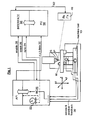
- The invention will now be described with reference to the drawing, wherein the figure shows one embodiment of a measurement system according to the invention.
- The figure shows a
machine tool 10 having a control device NC 20. The NC is used to control all functions of the machine tool. Shown in the drawing are servo control and positionfeedback lines 30. These lines are used to control x,y and z movements of the machine. A spindle S (in this instance fixed in position) can accept a measurement probe P. The probe is used to check the dimensions of workpiece w mounted to the machine tool as the workpiece is moved in x,y or z directions. The probe P is of a type which can produce varying data representing the deflection of its stylus in x,y or z and can produce many results per second. The stylus deflection data is transmitted wirelessly to a receiver/transmitter Rx/Tx 40. The NC 20 has position feedback lines which are also capable of receiving varying data relating to the x,y and z positions of the machine many times per second. - A PC 50 is provided which has an
interface circuit 60 e.g. a PCI,PCMCIA, Ethernet or USB type. The interface is capable of receiving and buffering data from the Rx/Tx along line 62, relating to probe stylus deflections. In this embodiment line 62 also provides for sending probe instructions. The PC accepts data vialine 32, relating to the positional machine tool movements. In the present embodiment the machine tool movements are directed straight to the PC, but they could be routed viainterface 60. - The interface can be used to buffer data received from the probe (and from the NC if appropriate). The buffer can store the data to send to the PC later. The interface can also use immediately the data coming from the probe to monitor conditions which require action e.g. over-deflection of the probe stylus. In such an instance of over-deflection the interface could issue a signal immediately to stop or reverse the machine's movements. Machine position data gathered immediately before the stop can be used to facilitate such action.
- Where the interface is in control of real time over-deflection etc monitoring, then it is possible that the PC can instruct the interface to alter conditions at which over-deflection etc is deemed to have occurred so that undesirable effects such as false triggering due to vibration or rapid movement of the probe are taken into account.
- These two sets of data can be used by the PC to produce an accurate profile of the workpiece W. However, useful computation can be carried out only if the two sets of data can be combined. In order for this to happen the relative time at which sets of data were obtained must be known. In operation the NC collects data relating to the machine tool movement and tabulates that data in order according to a regular synchronisation signal from an
internal clock 22. - The
internal clock 22 produces thesynchronisation signal 24 and the interface accepts this signal. A call for data from the probe is sent to the probe along path 62 in response to the synchronisation signal received at theinterface 60. The interface too collects data relating to probe stylus deflection and the PC tabulates that data in order according to the synchronisation signal from theinternal clock 22. In practice the PC can combine elements of the NC data with elements of the probe data because both are in the same order and will be in the same or related field of their respective tables. - The PC can thus carry out computation using the data from the same or related fields in each of the tabulated data from the NC and the probe.
- Speed of transfer of data to the PC from the NC and interface is not significant to the measurement speed of this system. The speed of transfer of data to the PC from the NC and interface will be dependent on the data transfer rate and the size of the memory buffers in the NC and the interface.
- Typically the system will operate in the following manner:
- the NC will run a program e.g. a program for cutting a workpiece W;
- the NC will run an inspection routine which includes the selection of the measurement probe P and the movement of the workpiece W past the probe along a nominal path defined by the inspection routine; and
- during the routine both the position of the machine tool and the deflection of the stylus of the probe are recorded in the manner described above.
- The PC can compute such things as workpiece size or form, workpiece surface finish and the assessment of scrap workpieces. Using such data it can also compute revised cutting tool paths and new feed and speed rates. In use of the system the two data sets are combined in the pc and used to determine the physical dimensions of a workpiece e.g. by adding or subtracting probe data to or from machine position data. This combined data can then be used to influence the further manufacturing of the workpiece or subsequently produced workpieces. This is done by altering the NC program or machine settings used to manufacture the workpiece.
- If required the
interface 60 can manipulate the data from the probe P so that, for example it is retarded or advanced to match theposition data 32 from the machine tool. In this way repeatable delays from the NC or measurement device can be accommodated. It is also possible to collect more data from the measurement device or NC than the other. In an example the synchronisation signal is multiplied atinterface 60 and many calls for data from the probe are sent to the probe along path 62. The calls for data occur at the multiplied rate. Thus data from the probe will be more numerous than the data from the NC. Measurement device data can be collected at say 10 times the rate of the NC position data so that filtering of the measurement device data can occur in the PC, resulting in better accuracy of measurement. - To avoid breakage of the probe, one or more event signals may be incorporated into the interface circuit. Should conditions occur for example deflection of the stylus greater than a threshold then the event signals are sent to the NC along line(s) 26. Such a signal will stop the machine via a conventional skip signal so that the unexpected problem can be overcome.
- The measurement device and the interface may have multiple operating modes and these modes may be selected via signals sent to the interface from the PC or from the NC e.g. the enable signal 28 starts the data collection from the measurement probe. In practice the
synchronisation signal 24 runs continuously but data from the probe and/or NC are recorded only when the enablesignal 28 is activated. Then enable signal is activated by commands within the NC program. - Many variants will be apparent to the skilled addressee. The separate NC and PC illustrated these may be integral. The measurement device illustrated is a measurement probe but other measurement devices can be used e.g. cameras or thermometers. The measurement device need not have wireless communication. A hardwired arrangement is possible. The probe used is capable of generating a stream of deflection data. The probe could also be used in a touch trigger mode i.e. a predetermined stylus deflection causes just one trigger signal. Such a mode of operation may be useful e.g. when initially setting up a workpiece, when the size of the part is not known exactly. A skip signal (like the event signal described) can be used as a touch trigger signal. The x,y,
z position data 32 shown might be replaced or supplemented by non Cartesian data and could be fed into the interface rather than into the PC as illustrated. - Alternatively, in touch trigger mode the data collected from the probe and from the NC can be manipulated to give an apparent touch trigger operation e.g. by employing an algorithm which extrapolates data back to a notional zero point, allowing improved repeatability.
- The
synchronisation signal 24 is illustrated as originating at the NC. However the signal could come from another source, e.g. from the interface, programmable logic control, a scale reading system or a drive system. Thus it is possible that the NC would await the synchronisation signal and produce position data related to the time at which the signal occurs. The interface would do the same or may issue a synchronisation signal when it records measurement device data, e.g. at every tenth recording of data. - Alternatively the probe could have a clock, data issuing from the clock acting as a synchronisation signal to initiate a data recording of the machine's position. If both the probe and either the interface or machine tool controller have a clock then the clocks can be kept in lock by occasional linking signals. Data from a master source can be given the correct real time.
- If real time identification of the data set of the probe and the data set of the position data from the machine tool is performed then the real time at which the two data sets is collected need not be the same. It would be possible to interpolate one set of data with respect to the other so that one or both sets of data are manipulated to arrive at an approximation of the data that would be expected if the two data sets were recorded at the same time.
- In refinements of the invention it is possible to filter probe data prior to their combination with position data. This might be done when more probe data is collected than is required and the data can be averaged to eliminate vibration errors. More probe data can be produced by multiplying the synchronisation signal at the
interface 60 and calling for data more often than the synchronisation signal occurrences. - In an alternative arrangement the synchronisation signal is not used to call for data from the probe, but is used to pick out data from a stream of data arriving at the
interface 60. - If a fixed time delay is used and added to one set of data, then corrections for processing delays can be accommodated.
- In practice the data stored in the second set may be data which has had machine errors e.g. due to thermal growth, corrected by separate software used in the NC, or other machine part.
- The system described above allows collection of data from a probe and machine position data in a way which allows its later combination. Present NC controllers do not allow real time external access to machine position data and this system overcomes this problem.
Claims (15)
- A workpiece inspection system comprising a machine tool which has a controller operable to perform a workpiece producing process and a workpiece inspection process, the inspection process including a method for synchronising varying data relating to measurements of the workpiece from a measurement device with varying data relating to machine position from the machine tool, comprising in any suitable order the steps of:mounting the measurement device on the machine tool;changing the position of the workpiece relative to the measurement device;issuing synchronisation signals defining a plurality of instants;causing measurements of the workpiece to be recorded which in particular involves:recording a first data set comprising varying data relating to the position of the machine; andrecording a second data set comprising varying data from the measurement device relating to measurements of the workpiece;in which the synchronisation signals are used in the recording of the first and second data sets such that simultaneous measurement device position and workpiece measurement data can be determined and subsequently combined.
- A workpiece inspection system as claimed in claim 1 wherein the synchronisation signal issues from the controller.
- A workpiece inspection system as claimed in claim 1 wherein the synchronisation signal is used to identify the real time at which at least some of the members of the first and second sets of data from the machine tool and measurement device were recorded in order that the position data and the measurement data can be combined with a related real time.
- A workpiece inspection system as claimed in claim 1 in which the synchronisation signals are used to label machine position data and workpiece measurement data at the time the synchronisation signal was issued.
- A workpiece inspection system as claimed in claim 1 wherein the measurement device is monitored at intervals which are more frequent than the occurrences of the said instants and only selected data is recorded to the second set and/or the data is manipulated prior to its recording.
- A workpiece inspection system as claimed in claim 1 wherein the system is configured to combine the data of the first and second sets.
- A workpiece inspection system as claimed in claim 6, wherein the system is further configured to influence the workpiece producing process performed at the controller of the machine tool on the basis of the combined data.
- A workpiece inspection system as claimed in any one preceding claim wherein the system further includes an interface circuit which accepts the synchronisation signal and the varying data from the measurement device.
- A workpiece inspection system as claimed in claim 1 wherein the system includes a stop signal path from the measurement device to the machine controller and the machine controller can be configured to stop the machine if a stop signal is received by the machine controller.
- A workpiece inspection system as claimed in claim 1 wherein the measurement device is a contact type dimensional measurement probe and the varying data relates to changes in the deflection of a workpiece contact stylus connected to the probe.
- A workpiece inspection system as claimed in claim 5 wherein the first set of data is corrected to at least reduce positional errors of the machine tool, prior to combination with the second set.
- A workpiece inspection system as claimed in claim 1 wherein the first and/or second sets of data are manipulated such that the manipulated data represents approximately the data which would have been obtained had the elements of the two sets been recorded simultaneously.
- A workpiece inspection system as claimed in claim 1 wherein the controller issues a further signal which enables the recording of the second set.
- Software for controlling a workpiece inspection system according to the steps claimed in claim 1.
- A workpiece inspection system comprising a machine tool having a first part, a second part movable relative to the first part, and a controller operable to perform both a workpiece production process and a workpiece inspection process and for producing varying data relating to the relative position of the first and second parts, the system comprising also a workpiece measurement device attached to the second machine part for producing varying data relating to measurements of the workpiece and a synchronisation signal producer, the system being operable such that the following workpiece inspection steps are performed:mounting the measurement device on the second part of the machine tool;changing the position of the workpiece relative to the measurement device;issuing synchronisation signals defining a plurality of instants;causing measurements of the workpiece to be recorded which in particular involves;recording a first data set comprising varying machine position data relating to the relative position of the first and second parts of the machine; and
recording a second data set comprising varying measurement device measurement data from the measurement device relating to measurements of the workpiece;
in which the synchronisation signals are used in the recording of the first and second data sets such that simultaneous measurement device position and workpiece measurement data can be determined and subsequently combined.
Applications Claiming Priority (2)
| Application Number | Priority Date | Filing Date | Title |
|---|---|---|---|
| GBGB0400144.2A GB0400144D0 (en) | 2004-01-06 | 2004-01-06 | Inspection system |
| EP05701794A EP1709498A2 (en) | 2004-01-06 | 2005-01-06 | Machine tool workpiece inspection system |
Related Parent Applications (2)
| Application Number | Title | Priority Date | Filing Date |
|---|---|---|---|
| EP05701794A Division EP1709498A2 (en) | 2004-01-06 | 2005-01-06 | Machine tool workpiece inspection system |
| EP05701794.9 Division | 2005-01-06 |
Publications (2)
| Publication Number | Publication Date |
|---|---|
| EP2267563A1 true EP2267563A1 (en) | 2010-12-29 |
| EP2267563B1 EP2267563B1 (en) | 2018-06-27 |
Family
ID=31503453
Family Applications (2)
| Application Number | Title | Priority Date | Filing Date |
|---|---|---|---|
| EP10010261.5A Expired - Lifetime EP2267563B1 (en) | 2004-01-06 | 2005-01-06 | Machine tool workpiece inspection system |
| EP05701794A Withdrawn EP1709498A2 (en) | 2004-01-06 | 2005-01-06 | Machine tool workpiece inspection system |
Family Applications After (1)
| Application Number | Title | Priority Date | Filing Date |
|---|---|---|---|
| EP05701794A Withdrawn EP1709498A2 (en) | 2004-01-06 | 2005-01-06 | Machine tool workpiece inspection system |
Country Status (6)
| Country | Link |
|---|---|
| US (1) | US7970488B2 (en) |
| EP (2) | EP2267563B1 (en) |
| JP (1) | JP5274775B2 (en) |
| CN (1) | CN100461049C (en) |
| GB (1) | GB0400144D0 (en) |
| WO (1) | WO2005065884A2 (en) |
Families Citing this family (53)
| Publication number | Priority date | Publication date | Assignee | Title |
|---|---|---|---|---|
| FR2892034A1 (en) * | 2005-10-14 | 2007-04-20 | Soudure Autogene Francaise Sa | ARC WELDING STATION WITH DATA MASS STORAGE MEMORY |
| EP1783569B1 (en) * | 2005-10-21 | 2018-08-29 | Omron Corporation | Data collection system |
| DE102007029151A1 (en) | 2006-12-15 | 2008-06-26 | Siemens Ag | Pulse delivery device for the accurate delivery of trigger pulses |
| GB0703423D0 (en) * | 2007-02-22 | 2007-04-04 | Renishaw Plc | Calibration method and apparatus |
| JP4532577B2 (en) | 2008-05-23 | 2010-08-25 | ファナック株式会社 | Machine tool with numerical control device and on-machine measuring device |
| JP4653824B2 (en) * | 2008-07-29 | 2011-03-16 | ファナック株式会社 | A machine tool system that measures the shape of a measurement object using an on-machine measuring device |
| JP5276488B2 (en) | 2009-03-20 | 2013-08-28 | 株式会社森精機製作所 | Workpiece measuring apparatus and method for machine tool |
| JP5283563B2 (en) * | 2009-05-16 | 2013-09-04 | 株式会社森精機製作所 | Workpiece measuring apparatus and method for machine tool |
| JP5237153B2 (en) * | 2009-02-24 | 2013-07-17 | 株式会社森精機製作所 | Workpiece measuring apparatus and method for machine tool |
| JP5473665B2 (en) * | 2010-02-17 | 2014-04-16 | Dmg森精機株式会社 | Workpiece measuring apparatus and method for machine tool |
| JP5437891B2 (en) | 2010-04-12 | 2014-03-12 | Dmg森精機株式会社 | Workpiece measuring apparatus and method for machine tool |
| JP5311294B2 (en) * | 2010-04-28 | 2013-10-09 | 株式会社安川電機 | Robot contact position detector |
| JP5218470B2 (en) * | 2010-04-28 | 2013-06-26 | 株式会社安川電機 | Robot work success / failure determination apparatus and method |
| US9976851B2 (en) | 2010-05-03 | 2018-05-22 | United Technologies Corporation | Accurate machine tool inspection of turbine airfoil |
| US9453716B2 (en) * | 2010-10-22 | 2016-09-27 | Makino Milling Machine Co., Ltd. | Method of measurement and apparatus for measurement of tool dimensions |
| TWI458938B (en) | 2011-01-19 | 2014-11-01 | Renishaw Plc | Analogue measurement probe for a machine tool apparatus |
| JP5221744B2 (en) * | 2011-11-28 | 2013-06-26 | ファナック株式会社 | Wire electric discharge machining method and wire electric discharge machine for machining a tool using an ultra-hard material attached to a rotating shaft |
| JP6165461B2 (en) * | 2012-03-13 | 2017-07-19 | 東芝機械株式会社 | Processing equipment with on-machine measurement function |
| US9726481B2 (en) | 2012-04-18 | 2017-08-08 | Renishaw Plc | Method of analogue measurement scanning on a machine tool |
| WO2013156767A1 (en) | 2012-04-18 | 2013-10-24 | Renishaw Plc | A method of finding a feature using a machine tool |
| US10037017B2 (en) | 2012-04-18 | 2018-07-31 | Renishaw Plc | Method of measurement on a machine tool and corresponding machine tool apparatus |
| CN103419081A (en) * | 2012-05-16 | 2013-12-04 | 辅佳材料科技股份有限公司 | Bench synchronous positioning compensation system |
| CN102759900B (en) * | 2012-06-29 | 2014-11-05 | 上海三一精机有限公司 | System and method for testing machine tool spindle thermal error |
| CN103009193A (en) * | 2012-12-10 | 2013-04-03 | 成都飞机工业(集团)有限责任公司 | Non-contact three-dimensional on-line measurement system for large structural member |
| DE102013015237A1 (en) | 2013-09-13 | 2015-03-19 | Blum-Novotest Gmbh | Roughness measuring instrument for use in a machine tool and method for measuring roughness in a machine tool |
| TWI528123B (en) | 2013-11-25 | 2016-04-01 | 財團法人資訊工業策進會 | Embedded system, fool-proof control method and computer-readable storage medium |
| WO2015097893A1 (en) * | 2013-12-27 | 2015-07-02 | 株式会社牧野フライス製作所 | Control apparatus for machine tool |
| CN105643362A (en) * | 2014-11-13 | 2016-06-08 | 沈阳高精数控智能技术股份有限公司 | Five-axis machine tool measuring method based on AxiSet |
| GB201505999D0 (en) * | 2015-04-09 | 2015-05-27 | Renishaw Plc | Measurement method and apparatus |
| CN107615197B (en) * | 2015-05-12 | 2020-07-14 | 三菱电机株式会社 | CNC device |
| DE102015006636A1 (en) * | 2015-05-22 | 2016-11-24 | Blum-Novotest Gmbh | Method and system for detecting a workpiece contour and for correcting a desired path for machining a workpiece in a machine tool |
| CN105204434A (en) * | 2015-09-15 | 2015-12-30 | 芜湖日升重型机床有限公司 | Informatization measurement and control system for numerical control machine tool |
| US10215547B2 (en) | 2016-06-24 | 2019-02-26 | Mitutoyo Corporation | Method for operating a coordinate measuring machine |
| US9970744B2 (en) | 2016-06-24 | 2018-05-15 | Mitutoyo Corporation | Method for operating a coordinate measuring machine |
| JP6829062B2 (en) * | 2016-11-29 | 2021-02-10 | ヘキサゴン・メトロジー株式会社 | Three-dimensional measuring device |
| CN110035867B (en) * | 2016-12-08 | 2020-07-28 | 三菱电机株式会社 | CNC device |
| GB201700879D0 (en) * | 2017-01-18 | 2017-03-01 | Renishaw Plc | Machine tool apparatus |
| JP6474439B2 (en) | 2017-02-22 | 2019-02-27 | ファナック株式会社 | Data collection device and data collection program |
| JP6499706B2 (en) | 2017-03-31 | 2019-04-10 | ファナック株式会社 | Data collection management system, data collection management method and program for managing data collection of a plurality of machines |
| KR101823052B1 (en) | 2017-04-17 | 2018-01-31 | 정만종 | Method of measuring workpiece for correction of cnc machine job |
| US11989887B2 (en) * | 2017-12-25 | 2024-05-21 | Nikon Corporation | Processing system, measuring probe, shape measuring device, and program |
| JP6919596B2 (en) | 2018-03-01 | 2021-08-18 | オムロン株式会社 | Measurement system and method |
| JP7249769B2 (en) * | 2018-12-17 | 2023-03-31 | ヘキサゴン・メトロジー株式会社 | CNC processing equipment |
| CN110488512B (en) * | 2019-06-11 | 2021-12-24 | 惠科股份有限公司 | Correction method and correction system of display panel measuring equipment |
| DE102019122655A1 (en) * | 2019-08-22 | 2021-02-25 | M & H Inprocess Messtechnik Gmbh | Measuring system |
| TW202131120A (en) | 2020-01-31 | 2021-08-16 | 財團法人工業技術研究院 | Cutting tool management method for machine tool |
| GB202002562D0 (en) | 2020-02-24 | 2020-04-08 | Renishaw Plc | Measurement method |
| EP4119290A4 (en) * | 2020-03-09 | 2023-11-22 | Hexagon Metrology Kabushiki Kaisha | CNC MACHINING DEVICE |
| US11243507B2 (en) * | 2020-04-29 | 2022-02-08 | Grale Technologies | Morphic manufacturing |
| EP4293444A1 (en) * | 2022-06-14 | 2023-12-20 | Siemens Aktiengesellschaft | Integration of a continuous measuring probe into a numerical control |
| EP4372502A1 (en) | 2022-11-18 | 2024-05-22 | Renishaw PLC | System and method for industrial manufacturing using machine tools and wireless measurement probes |
| JP7395067B1 (en) * | 2023-01-12 | 2023-12-08 | 三菱電機株式会社 | On-machine measurement device, on-machine measurement system, and on-machine measurement method |
| CN119827491B (en) * | 2024-12-31 | 2025-11-11 | 长春光华微电子设备工程中心有限公司 | High-precision material sheet scanning method, device and equipment based on probe function |
Citations (5)
| Publication number | Priority date | Publication date | Assignee | Title |
|---|---|---|---|---|
| US4811253A (en) * | 1985-03-30 | 1989-03-07 | Ae Plc | Method and apparatus for the measurement of airfoils |
| US4974165A (en) * | 1988-11-28 | 1990-11-27 | Mechanical Technology Incorporated | Real time machining control system including in-process part measuring and inspection |
| US5428548A (en) | 1992-09-12 | 1995-06-27 | Renishaw Plc | Method of and apparatus for scanning the surface of a workpiece |
| US5773731A (en) * | 1995-05-23 | 1998-06-30 | Toyoda Koki Kabushiki Kaisha | Method and apparatus for detecting residual grinding amount |
| US6098452A (en) * | 1997-10-17 | 2000-08-08 | Tokyo Seimitsu Co., Ltd. | Machine control gage system performing roughness and roundness measuring functions |
Family Cites Families (9)
| Publication number | Priority date | Publication date | Assignee | Title |
|---|---|---|---|---|
| US4138718A (en) * | 1977-11-14 | 1979-02-06 | Allen-Bradley Company | Numerical control system with downloading capability |
| US4885836A (en) * | 1988-04-19 | 1989-12-12 | Imta | Riveting process and apparatus |
| JPH05208345A (en) * | 1992-01-30 | 1993-08-20 | Murata Mach Ltd | Outside machine measuring instrument of machine tool |
| JPH07210228A (en) * | 1994-01-13 | 1995-08-11 | Japan Small Corp | Control method for measuring system using nc machine tool |
| JPH07286846A (en) * | 1994-04-20 | 1995-10-31 | Tokyo Seimitsu Co Ltd | Method and instrument for measuring shape of surface having noncontinuous part |
| US6539642B1 (en) * | 1999-03-03 | 2003-04-01 | Riken | Probe type shape measuring sensor, and NC processing equipment and shape measuring method using the sensor |
| US6519860B1 (en) * | 2000-10-19 | 2003-02-18 | Sandia Corporation | Position feedback control system |
| US6668466B1 (en) * | 2000-10-19 | 2003-12-30 | Sandia Corporation | Highly accurate articulated coordinate measuring machine |
| DE10144006A1 (en) * | 2001-09-07 | 2003-04-30 | Siemens Ag | Message Diagnostic Procedure |
-
2004
- 2004-01-06 GB GBGB0400144.2A patent/GB0400144D0/en not_active Ceased
-
2005
- 2005-01-06 JP JP2006548379A patent/JP5274775B2/en not_active Expired - Fee Related
- 2005-01-06 US US10/583,353 patent/US7970488B2/en not_active Expired - Lifetime
- 2005-01-06 EP EP10010261.5A patent/EP2267563B1/en not_active Expired - Lifetime
- 2005-01-06 WO PCT/GB2005/000023 patent/WO2005065884A2/en not_active Ceased
- 2005-01-06 EP EP05701794A patent/EP1709498A2/en not_active Withdrawn
- 2005-01-06 CN CNB200580001888XA patent/CN100461049C/en not_active Expired - Lifetime
Patent Citations (5)
| Publication number | Priority date | Publication date | Assignee | Title |
|---|---|---|---|---|
| US4811253A (en) * | 1985-03-30 | 1989-03-07 | Ae Plc | Method and apparatus for the measurement of airfoils |
| US4974165A (en) * | 1988-11-28 | 1990-11-27 | Mechanical Technology Incorporated | Real time machining control system including in-process part measuring and inspection |
| US5428548A (en) | 1992-09-12 | 1995-06-27 | Renishaw Plc | Method of and apparatus for scanning the surface of a workpiece |
| US5773731A (en) * | 1995-05-23 | 1998-06-30 | Toyoda Koki Kabushiki Kaisha | Method and apparatus for detecting residual grinding amount |
| US6098452A (en) * | 1997-10-17 | 2000-08-08 | Tokyo Seimitsu Co., Ltd. | Machine control gage system performing roughness and roundness measuring functions |
Non-Patent Citations (1)
| Title |
|---|
| "Control and Drive Systems Electronic Documentation system version 07", 2000, REXROTH INDRAMAT, XP002361192 * |
Also Published As
| Publication number | Publication date |
|---|---|
| JP5274775B2 (en) | 2013-08-28 |
| WO2005065884A3 (en) | 2006-04-27 |
| EP2267563B1 (en) | 2018-06-27 |
| CN1906550A (en) | 2007-01-31 |
| EP1709498A2 (en) | 2006-10-11 |
| CN100461049C (en) | 2009-02-11 |
| US20080051927A1 (en) | 2008-02-28 |
| GB0400144D0 (en) | 2004-02-11 |
| JP2007518579A (en) | 2007-07-12 |
| US7970488B2 (en) | 2011-06-28 |
| WO2005065884A2 (en) | 2005-07-21 |
Similar Documents
| Publication | Publication Date | Title |
|---|---|---|
| US7970488B2 (en) | Machine tool workpiece inspection system | |
| US11674789B2 (en) | Machine tool apparatus | |
| CN102282441B (en) | For optimizing the method measuring the cycle of contact coordinate location device | |
| EP3260811B1 (en) | Method for operating a coordinate measuring machine | |
| US12030152B2 (en) | Tool-checking device in a workpiece processing machine | |
| EP3837560B1 (en) | Method, computer program and apparatus for measurement cycle generation in a touch trigger coordinate machine | |
| US7367133B2 (en) | Device and method for coordinate measurement | |
| Hanafi et al. | An active axis control system for a conventional CNC machine | |
| CN100483070C (en) | Device and method for coordinate measurement |
Legal Events
| Date | Code | Title | Description |
|---|---|---|---|
| PUAI | Public reference made under article 153(3) epc to a published international application that has entered the european phase |
Free format text: ORIGINAL CODE: 0009012 |
|
| AC | Divisional application: reference to earlier application |
Ref document number: 1709498 Country of ref document: EP Kind code of ref document: P |
|
| AK | Designated contracting states |
Kind code of ref document: A1 Designated state(s): AT BE BG CH CY CZ DE DK EE ES FI FR GB GR HU IE IS IT LI LT LU MC NL PL PT RO SE SI SK TR |
|
| 17P | Request for examination filed |
Effective date: 20110621 |
|
| REG | Reference to a national code |
Ref country code: DE Ref legal event code: R079 Ref document number: 602005054198 Country of ref document: DE Free format text: PREVIOUS MAIN CLASS: G05B0019404000 Ipc: G05B0019401000 |
|
| RIC1 | Information provided on ipc code assigned before grant |
Ipc: G05B 19/401 20060101AFI20171222BHEP |
|
| GRAJ | Information related to disapproval of communication of intention to grant by the applicant or resumption of examination proceedings by the epo deleted |
Free format text: ORIGINAL CODE: EPIDOSDIGR1 |
|
| STAA | Information on the status of an ep patent application or granted ep patent |
Free format text: STATUS: GRANT OF PATENT IS INTENDED |
|
| GRAP | Despatch of communication of intention to grant a patent |
Free format text: ORIGINAL CODE: EPIDOSNIGR1 |
|
| INTG | Intention to grant announced |
Effective date: 20180212 |
|
| GRAS | Grant fee paid |
Free format text: ORIGINAL CODE: EPIDOSNIGR3 |
|
| GRAA | (expected) grant |
Free format text: ORIGINAL CODE: 0009210 |
|
| STAA | Information on the status of an ep patent application or granted ep patent |
Free format text: STATUS: THE PATENT HAS BEEN GRANTED |
|
| AC | Divisional application: reference to earlier application |
Ref document number: 1709498 Country of ref document: EP Kind code of ref document: P |
|
| AK | Designated contracting states |
Kind code of ref document: B1 Designated state(s): AT BE BG CH CY CZ DE DK EE ES FI FR GB GR HU IE IS IT LI LT LU MC NL PL PT RO SE SI SK TR |
|
| REG | Reference to a national code |
Ref country code: GB Ref legal event code: FG4D |
|
| REG | Reference to a national code |
Ref country code: AT Ref legal event code: REF Ref document number: 1012858 Country of ref document: AT Kind code of ref document: T Effective date: 20180715 |
|
| REG | Reference to a national code |
Ref country code: DE Ref legal event code: R096 Ref document number: 602005054198 Country of ref document: DE |
|
| REG | Reference to a national code |
Ref country code: IE Ref legal event code: FG4D |
|
| PG25 | Lapsed in a contracting state [announced via postgrant information from national office to epo] |
Ref country code: LT Free format text: LAPSE BECAUSE OF FAILURE TO SUBMIT A TRANSLATION OF THE DESCRIPTION OR TO PAY THE FEE WITHIN THE PRESCRIBED TIME-LIMIT Effective date: 20180627 Ref country code: BG Free format text: LAPSE BECAUSE OF FAILURE TO SUBMIT A TRANSLATION OF THE DESCRIPTION OR TO PAY THE FEE WITHIN THE PRESCRIBED TIME-LIMIT Effective date: 20180927 Ref country code: SE Free format text: LAPSE BECAUSE OF FAILURE TO SUBMIT A TRANSLATION OF THE DESCRIPTION OR TO PAY THE FEE WITHIN THE PRESCRIBED TIME-LIMIT Effective date: 20180627 Ref country code: FI Free format text: LAPSE BECAUSE OF FAILURE TO SUBMIT A TRANSLATION OF THE DESCRIPTION OR TO PAY THE FEE WITHIN THE PRESCRIBED TIME-LIMIT Effective date: 20180627 |
|
| REG | Reference to a national code |
Ref country code: NL Ref legal event code: MP Effective date: 20180627 |
|
| REG | Reference to a national code |
Ref country code: LT Ref legal event code: MG4D |
|
| PG25 | Lapsed in a contracting state [announced via postgrant information from national office to epo] |
Ref country code: GR Free format text: LAPSE BECAUSE OF FAILURE TO SUBMIT A TRANSLATION OF THE DESCRIPTION OR TO PAY THE FEE WITHIN THE PRESCRIBED TIME-LIMIT Effective date: 20180928 |
|
| REG | Reference to a national code |
Ref country code: AT Ref legal event code: MK05 Ref document number: 1012858 Country of ref document: AT Kind code of ref document: T Effective date: 20180627 |
|
| PG25 | Lapsed in a contracting state [announced via postgrant information from national office to epo] |
Ref country code: NL Free format text: LAPSE BECAUSE OF FAILURE TO SUBMIT A TRANSLATION OF THE DESCRIPTION OR TO PAY THE FEE WITHIN THE PRESCRIBED TIME-LIMIT Effective date: 20180627 |
|
| PG25 | Lapsed in a contracting state [announced via postgrant information from national office to epo] |
Ref country code: RO Free format text: LAPSE BECAUSE OF FAILURE TO SUBMIT A TRANSLATION OF THE DESCRIPTION OR TO PAY THE FEE WITHIN THE PRESCRIBED TIME-LIMIT Effective date: 20180627 Ref country code: CZ Free format text: LAPSE BECAUSE OF FAILURE TO SUBMIT A TRANSLATION OF THE DESCRIPTION OR TO PAY THE FEE WITHIN THE PRESCRIBED TIME-LIMIT Effective date: 20180627 Ref country code: EE Free format text: LAPSE BECAUSE OF FAILURE TO SUBMIT A TRANSLATION OF THE DESCRIPTION OR TO PAY THE FEE WITHIN THE PRESCRIBED TIME-LIMIT Effective date: 20180627 Ref country code: AT Free format text: LAPSE BECAUSE OF FAILURE TO SUBMIT A TRANSLATION OF THE DESCRIPTION OR TO PAY THE FEE WITHIN THE PRESCRIBED TIME-LIMIT Effective date: 20180627 Ref country code: IS Free format text: LAPSE BECAUSE OF FAILURE TO SUBMIT A TRANSLATION OF THE DESCRIPTION OR TO PAY THE FEE WITHIN THE PRESCRIBED TIME-LIMIT Effective date: 20181027 Ref country code: PL Free format text: LAPSE BECAUSE OF FAILURE TO SUBMIT A TRANSLATION OF THE DESCRIPTION OR TO PAY THE FEE WITHIN THE PRESCRIBED TIME-LIMIT Effective date: 20180627 Ref country code: SK Free format text: LAPSE BECAUSE OF FAILURE TO SUBMIT A TRANSLATION OF THE DESCRIPTION OR TO PAY THE FEE WITHIN THE PRESCRIBED TIME-LIMIT Effective date: 20180627 |
|
| PG25 | Lapsed in a contracting state [announced via postgrant information from national office to epo] |
Ref country code: ES Free format text: LAPSE BECAUSE OF FAILURE TO SUBMIT A TRANSLATION OF THE DESCRIPTION OR TO PAY THE FEE WITHIN THE PRESCRIBED TIME-LIMIT Effective date: 20180627 |
|
| REG | Reference to a national code |
Ref country code: DE Ref legal event code: R097 Ref document number: 602005054198 Country of ref document: DE |
|
| PLBE | No opposition filed within time limit |
Free format text: ORIGINAL CODE: 0009261 |
|
| STAA | Information on the status of an ep patent application or granted ep patent |
Free format text: STATUS: NO OPPOSITION FILED WITHIN TIME LIMIT |
|
| PG25 | Lapsed in a contracting state [announced via postgrant information from national office to epo] |
Ref country code: DK Free format text: LAPSE BECAUSE OF FAILURE TO SUBMIT A TRANSLATION OF THE DESCRIPTION OR TO PAY THE FEE WITHIN THE PRESCRIBED TIME-LIMIT Effective date: 20180627 |
|
| 26N | No opposition filed |
Effective date: 20190328 |
|
| PG25 | Lapsed in a contracting state [announced via postgrant information from national office to epo] |
Ref country code: MC Free format text: LAPSE BECAUSE OF FAILURE TO SUBMIT A TRANSLATION OF THE DESCRIPTION OR TO PAY THE FEE WITHIN THE PRESCRIBED TIME-LIMIT Effective date: 20180627 Ref country code: SI Free format text: LAPSE BECAUSE OF FAILURE TO SUBMIT A TRANSLATION OF THE DESCRIPTION OR TO PAY THE FEE WITHIN THE PRESCRIBED TIME-LIMIT Effective date: 20180627 |
|
| REG | Reference to a national code |
Ref country code: CH Ref legal event code: PL |
|
| PG25 | Lapsed in a contracting state [announced via postgrant information from national office to epo] |
Ref country code: LU Free format text: LAPSE BECAUSE OF NON-PAYMENT OF DUE FEES Effective date: 20190106 |
|
| REG | Reference to a national code |
Ref country code: BE Ref legal event code: MM Effective date: 20190131 |
|
| REG | Reference to a national code |
Ref country code: IE Ref legal event code: MM4A |
|
| PG25 | Lapsed in a contracting state [announced via postgrant information from national office to epo] |
Ref country code: FR Free format text: LAPSE BECAUSE OF NON-PAYMENT OF DUE FEES Effective date: 20190131 |
|
| PG25 | Lapsed in a contracting state [announced via postgrant information from national office to epo] |
Ref country code: BE Free format text: LAPSE BECAUSE OF NON-PAYMENT OF DUE FEES Effective date: 20190131 |
|
| PG25 | Lapsed in a contracting state [announced via postgrant information from national office to epo] |
Ref country code: CH Free format text: LAPSE BECAUSE OF NON-PAYMENT OF DUE FEES Effective date: 20190131 Ref country code: LI Free format text: LAPSE BECAUSE OF NON-PAYMENT OF DUE FEES Effective date: 20190131 |
|
| PG25 | Lapsed in a contracting state [announced via postgrant information from national office to epo] |
Ref country code: IE Free format text: LAPSE BECAUSE OF NON-PAYMENT OF DUE FEES Effective date: 20190106 |
|
| PG25 | Lapsed in a contracting state [announced via postgrant information from national office to epo] |
Ref country code: TR Free format text: LAPSE BECAUSE OF FAILURE TO SUBMIT A TRANSLATION OF THE DESCRIPTION OR TO PAY THE FEE WITHIN THE PRESCRIBED TIME-LIMIT Effective date: 20180627 |
|
| PG25 | Lapsed in a contracting state [announced via postgrant information from national office to epo] |
Ref country code: PT Free format text: LAPSE BECAUSE OF FAILURE TO SUBMIT A TRANSLATION OF THE DESCRIPTION OR TO PAY THE FEE WITHIN THE PRESCRIBED TIME-LIMIT Effective date: 20181029 |
|
| PG25 | Lapsed in a contracting state [announced via postgrant information from national office to epo] |
Ref country code: CY Free format text: LAPSE BECAUSE OF FAILURE TO SUBMIT A TRANSLATION OF THE DESCRIPTION OR TO PAY THE FEE WITHIN THE PRESCRIBED TIME-LIMIT Effective date: 20180627 |
|
| PG25 | Lapsed in a contracting state [announced via postgrant information from national office to epo] |
Ref country code: HU Free format text: LAPSE BECAUSE OF FAILURE TO SUBMIT A TRANSLATION OF THE DESCRIPTION OR TO PAY THE FEE WITHIN THE PRESCRIBED TIME-LIMIT; INVALID AB INITIO Effective date: 20050106 |
|
| P01 | Opt-out of the competence of the unified patent court (upc) registered |
Effective date: 20230602 |
|
| PGFP | Annual fee paid to national office [announced via postgrant information from national office to epo] |
Ref country code: DE Payment date: 20240129 Year of fee payment: 20 Ref country code: GB Payment date: 20240123 Year of fee payment: 20 |
|
| PGFP | Annual fee paid to national office [announced via postgrant information from national office to epo] |
Ref country code: IT Payment date: 20240123 Year of fee payment: 20 |
|
| REG | Reference to a national code |
Ref country code: DE Ref legal event code: R071 Ref document number: 602005054198 Country of ref document: DE |
|
| REG | Reference to a national code |
Ref country code: GB Ref legal event code: PE20 Expiry date: 20250105 |
|
| PG25 | Lapsed in a contracting state [announced via postgrant information from national office to epo] |
Ref country code: GB Free format text: LAPSE BECAUSE OF EXPIRATION OF PROTECTION Effective date: 20250105 |