EP2267484B1 - Phantom für eine medizinische tomographische Abbildungsvorrichtung - Google Patents
Phantom für eine medizinische tomographische Abbildungsvorrichtung Download PDFInfo
- Publication number
- EP2267484B1 EP2267484B1 EP09008184.5A EP09008184A EP2267484B1 EP 2267484 B1 EP2267484 B1 EP 2267484B1 EP 09008184 A EP09008184 A EP 09008184A EP 2267484 B1 EP2267484 B1 EP 2267484B1
- Authority
- EP
- European Patent Office
- Prior art keywords
- phantom
- fluid container
- imaging apparatus
- medical imaging
- elongated
- Prior art date
- Legal status (The legal status is an assumption and is not a legal conclusion. Google has not performed a legal analysis and makes no representation as to the accuracy of the status listed.)
- Active
Links
Images



Classifications
-
- G—PHYSICS
- G01—MEASURING; TESTING
- G01T—MEASUREMENT OF NUCLEAR OR X-RADIATION
- G01T1/00—Measuring X-radiation, gamma radiation, corpuscular radiation, or cosmic radiation
- G01T1/16—Measuring radiation intensity
- G01T1/169—Exploration, location of contaminated surface areas
Definitions
- the invention relates to a phantom for simulation of an object (e.g. a patient) in a tomographic medical imaging apparatus.
- the invention relates to a tomographic medical imaging apparatus comprising such a phantom for simulation of an object, e.g. a patient.
- the U.S. patent 4,499,375 discloses the so-called Jaszczak phantom which is commonly used for testing of tomographic medical imaging apparatuses like single photon emission computed tomography (SPECT) apparatuses.
- the Jaszczak phantom comprises a cylindrical container made of acrylic glass which can be filled with a radioactive solution serving as a radio contrast agent.
- the Jaszczak phantom comprises several elongated structures in the form of parallel rods which are arranged within the cylindrical container.
- there are several groups of rods comprising different diameters so that the spatial resolution of the tomographic medical imaging apparatuses can be tested using the Jaszczak phantom.
- the conventional Jaszczak phantom does not allow a determination of the exact spatial resolution of a tomographic medical imaging apparatus since it is merely possible to determine an upper limit of the spatial resolution of the tomographic medical imaging apparatuses.
- a further disadvantage of the conventional Jaszczak phantom is associated with the regularity of the arrangement of the rods within the Jaszczak phantom which can cause problems with regard to the use of reconstruction methods using filters like the so-called Wiener filter.
- These reconstruction methods used in modern tomographic medical imaging apparatuses may amplify spatially regular structures like the arrangement of the rods thereby distorting the determination of the spatial resolution of the tomographic medical imaging apparatus.
- US 5 673 303 discloses a phantom for a tomography apparatus wherein the phantom comprises an elongated structure in the form of a stepped cylindrical insert. Therefore, the cross-section of the elongated structure varies over its length in a cascaded form.
- this conventional phantom does not allow a precise determination of the spatial resolution of the tomography apparatus.
- US 4 344 183 discloses a phantom comprising cone-shaped inserts.
- the cone-shaped inserts are made of plastics, i.e. they do not create an image pattern detected by the tomography. Instead, image creating patterns are embedded into the cone-shaped inserts. However, these image creating patterns have a constant cross-section and therefore do not allow a continuous measurement of the spatial resolution of the tomographic medical imaging apparatus.
- US 2009/0127451 A1 discloses a phantom comprising spherical regions of contrast.
- these spherical regions of contrast do not allow a continuous measurement of these spatial resolution of the tomographic medical imaging apparatus.
- the phantom preferably allows the testing of the tomographic medical imaging apparatus under different signal-to-noise ratios (SNR), lesion-to-background ratios and contrast-to-noise ratios.
- SNR signal-to-noise ratios
- the novel phantom comprises at least one elongated structure (e.g. an inner fluid container or a massive rod) for testing the spatial resolution of a tomographic medical imaging apparatus.
- the elongated structure comprises a cross section which varies over the length of the elongated structure.
- the elongated structure is an inner fluid container which is arranged within the phantom and which can be filled with a contrast fluid, e.g.
- the elongated structure is a massive or hollow rod having a cross section which varies over the length of the rod.
- the elongated structure is substantially cone-shaped so that the elongated structure tapers along its length.
- the cone-angle of the elongated structure can be in the range of 1°-10° and more preferably in the range of 2°-5°.
- the cross section of the elongated structure varies continuously over the length of the elongated structure in contrast to a cascaded change of the cross section over the length of the elongated structure.
- the continuous change of the cross-section of the elongated structures over their length allows a continuous measurement of the spatial resolution of the tomographic medical imaging apparatus.
- the afore-mentioned inner fluid container preferably comprises an inner diameter in the range of 1mm-20mm and more preferably in the range of 2mm-15mm, which is suitable for human SPECT applications.
- the inner diameter of the inner fluid containers is preferably in the range of 0.1mm-2mm.
- a diameter in the range of 0.5mm-10mm is preferred for positron emission tomography (PET).
- PET positron emission tomography
- a diameter in the range of 50 ⁇ m-1mm is preferred for computer tomography of human beings.
- a diameter in the range of 100 ⁇ m-2mm is preferred for magnetic resonance imaging (MRI).
- the preferred diameter of the inner fluid container depends on the type of imaging method (SPECT/CT/MRI) and the type of the object (human/animal).
- the lateral extension (e.g. diameter) of the elongated structure should vary between a smallest value below the spatial resolution of the tomographic medical imaging apparatus and a greatest value above the spatial resolution of the tomographic medical imaging apparatus. Such an arrangement allows an exact determination of the spatial resolution of the tomographic medical imaging apparatus.
- an inner fluid container as the elongated structure within the phantom allows a testing of a tomographic medical imaging apparatus with an active structure containing a radio contrast agent as opposed to a passive structure consisting of a massive rod as disclosed in the afore-mentioned U.S. patent 4,499,375 .
- the phantom according to the invention preferably comprises an outer fluid container surrounding the elongated structure, wherein the outer fluid container can be filled with a fluid, e.g. a contrast agent.
- a fluid e.g. a contrast agent.
- the inner fluid container on the one hand and the outer fluid container with different fluids, e.g. different radioactive liquids with different half-lives or different concentrations of activity.
- the individual inner fluid containers with different fluids, e.g. different radioactive liquids with a different concentration of activity.
- the phantom and/or the outer fluid container is preferably shaped as a half cylinder so that the phantom can easily be placed on a patient bed of a conventional tomographic medical imaging apparatus, wherein the convex side of the half cylinder is placed on the patient bed.
- the half-cylindrical shape of the outer fluid container or the outer cover is advantageous since the it allows to place the arrangement within a thorax-shaped phantom.
- the phantom comprises a different shape although it is preferred that the phantom comprises a substantially flat side face so that the phantom can easily be placed on a patient bed of a conventional tomographic medical imaging apparatus.
- the outer fluid container of the phantom comprises two opposing end faces which are preferably substantially parallel to each other.
- the elongated structure extends between the opposing end faces of the outer fluid containers. In other words, the elongated structure extends over the entire length of the outer fluid container.
- the elongated structure projects into the outer fluid container from one of the end faces of the outer fluid container without extending up to the opposing end face of the outer fluid container. In other words, the elongated structure merely extends over a portion of the length of the outer fluid container.
- the phantom preferably comprises two end plates closing the opposing end faces of the outer fluid container. Further, there is preferably a plurality of elongated structures which are attached to the opposing end plates of the phantom. For example, a first number of the elongated structures can be attached to the first end plate, while a second number of the elongated structures is attached to the second end plate opposite the first end plate.
- the elongated structures are preferably laterally displaced relative to each other so that the individual elongated structures are out of the sphere of influence of the adjacent elongated structures.
- the distance between the adjacent elongated structures is preferably sufficiently large to avoid an effect of the elongated structures on the measurement of the adjacent structures particularly during reconstruction.
- the elongated structures preferably taper along their length so that the elongated structures each comprise a base area and an opposing apex.
- the base area of the elongated structures is attached to the end plates and the apex of the elongated structures axially projects into the outer fluid container.
- elongated structures there are preferably several (e.g. more than 2, 4, 8 or more than 10) elongated structures within the phantom. In the preferred embodiment of the invention, there are twelve elongated structures arranged within the phantom.
- the elongated structures taper in opposing directions.
- each of the inner fluid containers preferably comprises an associated valve so that the inner fluid containers can be filled and emptied separately from each other.
- the elongated structures are preferably arranged in parallel within the phantom.
- the lateral distance between the adjacent elongated structures is preferably greater than the spatial resolution of the tomographic medical imaging apparatus.
- the afore-mentioned inner fluid container and/or the outer fluid container preferably comprises a wall which is at least partially transparent.
- the wall of the inner fluid container and/or the outer fluid container can be made of acrylic glass.
- the elongated structures are arranged substantially vertically within the phantom, wherein the elongated structures preferably taper from the upper side to the lower side of the phantom.
- the elongated structures are inner fluid containers since it facilitates the filling of the inner fluid containers.
- the tomographic medical imaging apparatus detects a specific radiation, which is used for SPECT and PET applications, wherein the radiation preferably comprises an energy in the range of 25keV to 511keV.
- the inner fluid container and/or the outer fluid container comprises walls which are preferably made from a material having a first attenuation coefficient regarding the radiation used by the tomographic medical imaging apparatus.
- water comprises a second attenuation coefficient with regard to the radiation used by the tomographic medical imaging apparatus.
- the material of the walls of the fluid containers is preferably selected in such a way that the first attenuation coefficient of the material of the walls of the fluid containers corresponds to the second attenuation coefficient of water.
- the first attenuation coefficient is preferably in a range of ⁇ 10 %, ⁇ 5 % or even ⁇ 1 % around the second attenuation coefficient.
- the afore-mentioned inner and outer fluid containers can be filled with a variety of fluids including gaseous fluids and liquid fluids, e.g. air, inactive water, a contrast agent (e.g. a radio contrast agent or an MRI contrast agent) or a radioactive liquid).
- gaseous fluids and liquid fluids e.g. air, inactive water, a contrast agent (e.g. a radio contrast agent or an MRI contrast agent) or a radioactive liquid).
- a contrast agent e.g. a radio contrast agent or an MRI contrast agent
- a radioactive liquid e.g. an MRI contrast agent
- the inner fluid containers on the one hand and the outer fluid container on the other hand can be filled with different fluids, e.g. radioactive fluids comprising a different concentration of activity.
- the phantom comprises several inner fluid containers, it is also possible to fill the inner fluid containers with different fluids, e.g. radioactive fluids comprising a different concentration of activity
- the phantom comprises an outer cover which is shaped as a part (e.g. a thorax) of a human body, wherein the inner fluid container and/or the outer fluid container is arranged within the outer cover.
- the invention also encompasses a tomographic medical imaging apparatus comprising the afore-mentioned phantom for testing the tomographic medical imaging apparatus.
- the invention is particularly suitable for testing a nuclear imaging apparatus, e.g. a single photon emission computed tomography (SPECT) apparatus or a positron emission tomography (PET) apparatus.
- SPECT single photon emission computed tomography
- PET positron emission tomography
- the tomographic medical imaging apparatus is a computer tomography (CT) apparatus or a magnetic resonance imaging (MRI) apparatus.
- CT computer tomography
- MRI magnetic resonance imaging
- the invention also encompasses the use of the afore-mentioned phantom for testing a tomographic medical imaging apparatus.
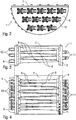
- Figures 1-4 show the preferred embodiment of a phantom 1 according to the invention.
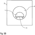
- the phantom 1 can be used for simulation of a human body during testing of a SPECT apparatus 2 (SPECT: s ingle p hoton e mission c omputed t omography) as shown in Figure 5A .
- SPECT s ingle p hoton e mission c omputed t omography
- Figure 5A a SPECT apparatus 2
- the phantom 1 is placed on a patient bed 3 of the SPECT apparatus 2 and moved into a cylindrical gantry opening 4 of the SPECT apparatus 2.
- the phantom 1 is substantially semi-cylindrical and comprises two semi-circular end plates 5, 6 which are mechanically connected by a flat base plate 7.
- the semi-cylindrical shape of the phantom 1 is advantageous since the phantom 1 can be easily placed on the patient bed 3 and moved into the gantry opening 4 of the SPECT apparatus 2.
- the phantom 1 comprises a first number of elongated structures in the form of cone-shaped inner containers 8 which are attached to the end plate 5. Further, the phantom 1 comprises a number of elongated structures in the form of inner containers 9 which are attached to the end plate 6.
- the inner containers 8 on the one hand and the inner containers 9 on the other hand taper in different directions.
- the inner fluid containers 8 are laterally displaced with regard to the inner fluid containers 9 so that the inner fluid containers 8 are out of the sphere of influence of the inner fluid containers 9 and vice versa.
- end plate 6 comprises several connections including a valve for filling and emptying the inner fluid containers 9.
- the end plate 5 also comprises several connections 11 including valves for filling and emptying the inner fluid containers 8.
- Figures 1-4 show the phantom 1 in a partially disassembled state without an outer cover so that the inner fluid containers 8, 9 are clearly visible.
- an outer cover made of acrylic glass is mounted onto the phantom thereby forming an outer fluid container surrounding the inner fluid containers 8, 9.
- the outer fluid container can itself be filled with a fluid, e.g. a radio contrast agent.
- inner fluid containers 8, 9 and the outer fluid container can be filled and emptied separately and with different contrast agents.
- Figure 5B shows a modification of the embodiment of Figure 5A .
- the phantom 1 comprises a different orientation within the gantry opening 4 with the convex side facing upwards.
- Figure 5C shows a modification of the embodiment of Figure 5A .
- the phantom 1 comprises a different orientation within the gantry opening 4 with the axis of the phantom 1 being aligned perpendicular to the axis of the SPECT apparatus 2.
- Such an orientation of the phantom 1 allows a determination of the spatial resolution not only in an axial direction but also in other directions.
Landscapes
- Physics & Mathematics (AREA)
- Health & Medical Sciences (AREA)
- Life Sciences & Earth Sciences (AREA)
- General Physics & Mathematics (AREA)
- High Energy & Nuclear Physics (AREA)
- Molecular Biology (AREA)
- Spectroscopy & Molecular Physics (AREA)
- Nuclear Medicine (AREA)
Claims (21)
- Phantom (1) zur Simulation eines Objekts in einer tomographischen medizinischen Bildgebungsvorrichtung (2), umfassend mindestens eine langgestreckte Struktur (8, 9) zum Testen der räumlichen Auflösung der tomographischen medizinischen Bildgebungsvorrichtung (2), wobei die langgestreckte Struktur (8, 9) ein massiver oder hohler Stab ist, der innerhalb des Phantoms (1) angeordnet ist, und wobei die langgestreckte Struktur (8, 9) einen Querschnitt aufweist, der über die Länge der langgestreckten Struktur (8, 9) variiert, dadurch gekennzeichnet, dass der Querschnitt der langgestreckten Struktur (8, 9) kontinuierlich über ihre Länge variiert, so dass sie eine kontinuierliche Messung der räumlichen Auflösung der tomographischen medizinischen Bildgebungsvorrichtung (2) erlaubt.
- Phantom (1) gemäß Anspruch 1, wobei die langgestreckte Struktur (8, 9) ein innerer Fluidbehälter (8, 9) ist, der innerhalb des Phantoms (1) angeordnet ist und der mit einem Fluid, insbesondere einem radioaktiven Fluid, gefüllt werden kann.
- Phantom (1) gemäß einem der vorangehenden Ansprüche, wobeia) der innere Fluidbehälter (8, 9) einen Innenquerschnitt aufweist, der über seine Länge variiert, und/oderb) die langgestreckte Struktur (8, 9) im Wesentlichen konusförmig ist, und/oderc) sich die langgestreckte Struktur (8, 9) entlang ihrer Länge verjüngt, und/oderd) der innere Fluidbehälter (8, 9) einen Innendurchmesser im Bereich von 2mm bis 15mm aufweist, insbesondere zur Einzelphotonen-Emissionscomputertomographie von Menschen, odere) der innere Fluidbehälter (8, 9) einen Innendurchmesser im Bereich von 0,1mm bis 10mm aufweist, insbesondere zur Einzelphotonen-Emissionscomputertomographie von kleinen Tieren, oderf) der innere Fluidbehälter (8, 9) einen Innendurchmesser im Bereich von 0,5mm bis 10mm aufweist, insbesondere zur Positronen-Emissions-Tomographie, oderg) der innere Fluidbehälter (8, 9) einen Innendurchmesser im Bereich von 50µm bis 1mm aufweist, insbesondere zur Computertomographie von Menschen, oderh) der innere Fluidbehälter (8, 9) einen Innendurchmesser im Bereich von 100µm bis 2mm aufweist, insbesondere zur Magnetresonanzbildgebung.
- Phantom (1) gemäß einem der vorangehenden Ansprüche, weiterhin aufweisend einen äußeren Fluidbehälter, der die langgestreckte Struktur (8, 9) umgibt, wobei der äußere Fluidbehälter mit einem Fluid gefüllt werden kann.
- Phantom (1) gemäß Anspruch 4, wobeia) das Phantom (1) und/oder der äußere Fluidbehälter im Wesentlichen als Halbzylinder geformt ist, und/oderb) das Phantom (1) und/oder der äußere Fluidbehälter eine im Wesentlichen flache Seitenfläche aufweist.
- Phantom (1) gemäß Anspruch 4 oder 5, wobeia) der äußere Fluidbehälter zwei gegenüberliegende Stirnflächen aufweist, und/oderb) die gegenüberliegenden Stirnflächen im Wesentlichen parallel sind, und/oderc) sich die langgestreckte Struktur (8, 9) zwischen den gegenüberliegenden Stirnflächen des äußeren Fluidbehälters erstreckt, oderd) die langgestreckte Struktur (8, 9) von einer der Stirnflächen des äußeren Fluidbehälters in den äußeren Fluidbehälter hineinragt ohne sich bis zu der gegenüberliegenden Stirnfläche des äußeren Fluidbehälters zu erstrecken.
- Phantom (1) gemäß einem der Ansprüche 4 bis 6, wobeia) das Phantom (1) eine erste Endplatte (5) aufweist, welche die erste Stirnfläche des äußeren Fluidbehälters abschließt, undb) das Phantom (1) eine zweite Endplatte (6) aufweist, welche eine zweite Stirnfläche des äußeren Fluidbehälters gegenüber der ersten Stirnfläche abschließt,c) eine erste Anzahl der langgestreckten Strukturen (8) an der ersten Endplatte (5) befestigt ist, undd) eine zweite Anzahl der langgestreckten Strukturen (9) an der zweiten Endplatte (6) befestigt ist.
- Phantom (1) gemäß Anspruch 7, wobeia) die erste Anzahl der langgestreckten Strukturen in seitlicher Richtung relativ zu der zweiten Anzahl der langgestreckten Strukturen (9) versetzt ist, und/oderb) die langgestreckten Strukturen (8, 9) außerhalb des Einflussbereichs des inneren Fluidbehälters (9) und umgekehrt liegen.
- Phantom (1) gemäß Anspruch 7 oder 8, wobeia) die langgestreckten Strukturen (8, 9) sich entlang ihrer Länge verjüngen, so dass die langgestreckten Strukturen (8, 9) jeweils einen Basisbereich und eine gegenüberliegende Spitze aufweisen, undb) der Basisbereich der langgestreckten Strukturen (8, 9) an den ersten und zweiten Endplatten (5, 6) befestigt ist, undc) die Spitze der langgestreckten Strukturen (8, 9) in axialer Richtung in den äußeren Fluidbehälter hineinragt.
- Phantom (1) gemäß einem der vorangehenden Ansprüche, wobeia) es mehrere langgestreckte Strukturen (8, 9) gibt, die innerhalb des Phantoms (1) angeordnet sind, undb) die langgestreckten Strukturen (8, 9) sich in entgegengesetzten Richtungen verjüngen, und/oderc) die inneren Fluidbehälter (8, 9) getrennt befüllt werden können, und/oderd) die langgestreckten Strukturen parallel angeordnet sind, und/odere) der seitliche Abstand zwischen den benachbarten langgestreckten Strukturen (8, 9) größer ist als die räumliche Auflösung der tomographischen medizinischen Bildgebungsvorrichtung (2).
- Phantom (1) gemäß einem der vorangehenden Ansprüche, wobei der innere Fluidbehälter (8, 9) und/oder der äußere Fluidbehälter eine Wand aufweist, die mindestens teilweise durchsichtig ist.
- Phantom (1) gemäß einem der vorangehenden Ansprüche, wobeia) die langgestreckten Strukturen (8, 9) im Wesentlichen vertikal innerhalb des Phantoms (1) angeordnet sind, undb) die langgestreckten Strukturen (8, 9) sich von der Oberseite zu der Unterseite des Phantoms (1) verjüngen, und/oderc) die langgestreckten Strukturen (8, 9) im Wesentlichen vertikal innerhalb des Phantoms (1) angeordnet sind.
- Phantom (1) gemäß einem der vorangehenden Ansprüche, wobeia) die inneren Fluidbehälter (8, 9) durch mindestens ein Ventil gefüllt oder entleert werden können, und/oderb) jeder der inneren Fluidbehälter (8, 9) ein zugehöriges Ventil zum Befüllen und Entleeren aufweist.
- Phantom (1) gemäß einem der vorangehenden Ansprüche, wobeia) die tomographische medizinische Bildgebungsvorrichtung (2) eine bestimmte Strahlung detektiert, wobei die Strahlung vorzugsweise eine Energie im Bereich von 25keV bis 511keV aufweist, undb) der innere Fluidbehälter (8, 9) und/oder der äußere Fluidbehälter Wände aufweist, die aus einem Material hergestellt sind, das einen ersten Abschwächungskoeffizienten bezüglich der von der tomographischen medizinischen Bildgebungsvorrichtung (2) verwendeten Strahlung aufweist, undc) Wasser einen zweiten Abschwächungskoeffizienten in Bezug auf die Strahlung aufweist, die von der tomographischen medizinischen Bildgebungsvorrichtung (2) verwendet wird, undd) der erste Abschwächungskoeffizient dem zweiten Abschwächungskoeffizienten entspricht und/odere) der erste Abschwächungskoeffizient im Bereich von ±10%, ±5% oder ±1% um den zweiten Abschwächungskoeffizienten liegt.
- Phantom (1) gemäß einem der vorangehenden Ansprüche, wobei die inneren Fluidbehälter (8, 9) gefüllt sind mita) Luft,b) inaktivem Wasser,c) einem Kontrastmittel, insbesondere einem Strahlungskontrastmittel oder einem MRI-Kontrastmittel, oderd) einer ersten radioaktiven Flüssigkeit.
- Phantom (1) gemäß einem der vorangehenden Ansprüche, wobei der äußere Fluidbehälter gefüllt ist mita) Luft,b) inaktivem Wasser,c) einem Kontrastmittel, insbesondere einem Strahlungskontrastmittel oder einem MRI-Kontrastmittel, oderd) einer zweiten radioaktiven Flüssigkeit.
- Phantom (1) gemäß einem der Ansprüche 4 bis 16, wobeia) der innere Fluidbehälter (8, 9) und der äußere Fluidbehälter mit verschiedenen Fluiden gefüllt sind, und/oderb) das Fluid in dem inneren Fluidbehälter (8, 9) eine andere Aktivitätskonzentration hat als das Fluid in dem äußeren Fluidbehälter.
- Phantom (1) gemäß einem der vorangehenden Ansprüche, weiterhin aufweisend eine äußere Abdeckung, die geformt ist als ein Teil eines menschlichen Körpers, insbesondere eines Brustkorbs, wobei der innere Fluidbehälter (8, 9) und/oder der äußere Fluidbehälter innerhalb der äußeren Abdeckung angeordnet ist.
- Tomographische medizinische Bildgebungsvorrichtung (2) umfassend ein Phantom (1) gemäß einem der vorangehenden Ansprüche.
- Tomographische medizinische Bildgebungsvorrichtung (2) gemäß Anspruch 19, wobei die tomographische medizinische Bildgebungsvorrichtung (2) ist:a) eine nukleare Bildgebungsvorrichtung (2), insbesondere eine Einzelphotonen-Emissionscomputertomographievorrichtung (2) oder eine Positronen-Emissions-Tomographievorrichtung, oderb) eine Computertomographievorrichtung, oderc) eine Magnetresonanztomographiebildgebungsvorrichtung.
- Verwendung eines Phantoms (1) gemäß einem der Ansprüche 1 bis 18 zum Testen einer tomographischen medizinischen Bildgebungsvorrichtung (2).
Priority Applications (4)
| Application Number | Priority Date | Filing Date | Title |
|---|---|---|---|
| HUE09008184A HUE035083T2 (en) | 2009-06-22 | 2009-06-22 | Phantom for tomography medical imaging equipment |
| EP09008184.5A EP2267484B8 (de) | 2009-06-22 | 2009-06-22 | Phantom für eine medizinische tomographische Abbildungsvorrichtung |
| NO09008184A NO2267484T3 (de) | 2009-06-22 | 2009-06-22 | |
| DK09008184.5T DK2267484T3 (da) | 2009-06-22 | 2009-06-22 | Fantom til et medicinsk tomografisk afbildningsapparat |
Applications Claiming Priority (1)
| Application Number | Priority Date | Filing Date | Title |
|---|---|---|---|
| EP09008184.5A EP2267484B8 (de) | 2009-06-22 | 2009-06-22 | Phantom für eine medizinische tomographische Abbildungsvorrichtung |
Publications (3)
| Publication Number | Publication Date |
|---|---|
| EP2267484A1 EP2267484A1 (de) | 2010-12-29 |
| EP2267484B1 true EP2267484B1 (de) | 2017-08-09 |
| EP2267484B8 EP2267484B8 (de) | 2017-10-04 |
Family
ID=42283147
Family Applications (1)
| Application Number | Title | Priority Date | Filing Date |
|---|---|---|---|
| EP09008184.5A Active EP2267484B8 (de) | 2009-06-22 | 2009-06-22 | Phantom für eine medizinische tomographische Abbildungsvorrichtung |
Country Status (4)
| Country | Link |
|---|---|
| EP (1) | EP2267484B8 (de) |
| DK (1) | DK2267484T3 (de) |
| HU (1) | HUE035083T2 (de) |
| NO (1) | NO2267484T3 (de) |
Families Citing this family (4)
| Publication number | Priority date | Publication date | Assignee | Title |
|---|---|---|---|---|
| TWI458467B (zh) * | 2011-09-30 | 2014-11-01 | Univ Chung Shan Medical | 動態斷層造影模擬藥物干擾之試驗裝置及其方法 |
| GB2519586B (en) * | 2013-10-28 | 2015-12-02 | Elekta ltd | Phantoms and associated methods for calibrating imaging systems |
| KR101729567B1 (ko) | 2015-10-30 | 2017-04-25 | 연세대학교 원주산학협력단 | 양전자 단층촬영 및 컴퓨터 단층촬영 전용 팬텀 |
| CN114487953A (zh) * | 2021-12-13 | 2022-05-13 | 中国科学院深圳先进技术研究院 | 一种磁共振仿体结构 |
Citations (3)
| Publication number | Priority date | Publication date | Assignee | Title |
|---|---|---|---|---|
| US4344183A (en) * | 1980-04-14 | 1982-08-10 | Radiation Measurements, Inc. | Measuring tool for computer assisted tomographic scanner |
| CA2693105A1 (en) * | 2007-06-29 | 2009-01-08 | King's College Hospital Nhs Foundation Trust | Phantom for imaging apparatuses |
| US20090127451A1 (en) * | 2007-11-16 | 2009-05-21 | Siemens Medical Solutions Usa, Inc. | Devices and Methods for Calibrating Nuclear Medical and Radiological Images |
Family Cites Families (4)
| Publication number | Priority date | Publication date | Assignee | Title |
|---|---|---|---|---|
| US4499375A (en) | 1982-05-10 | 1985-02-12 | Jaszczak Ronald J | Nuclear imaging phantom |
| US5673303A (en) * | 1995-04-19 | 1997-09-30 | Wright State University | Method and apparatus for the evaluation of structural width and density by computed tomography |
| US6744039B1 (en) * | 2001-06-14 | 2004-06-01 | Biomec, Inc. | Single-chamber fillable phantom for nuclear imaging |
| KR100517889B1 (ko) * | 2003-05-09 | 2005-09-30 | 주라형 | 영상정합 정확성 평가용 팬텀 |
-
2009
- 2009-06-22 EP EP09008184.5A patent/EP2267484B8/de active Active
- 2009-06-22 NO NO09008184A patent/NO2267484T3/no unknown
- 2009-06-22 HU HUE09008184A patent/HUE035083T2/en unknown
- 2009-06-22 DK DK09008184.5T patent/DK2267484T3/da active
Patent Citations (3)
| Publication number | Priority date | Publication date | Assignee | Title |
|---|---|---|---|---|
| US4344183A (en) * | 1980-04-14 | 1982-08-10 | Radiation Measurements, Inc. | Measuring tool for computer assisted tomographic scanner |
| CA2693105A1 (en) * | 2007-06-29 | 2009-01-08 | King's College Hospital Nhs Foundation Trust | Phantom for imaging apparatuses |
| US20090127451A1 (en) * | 2007-11-16 | 2009-05-21 | Siemens Medical Solutions Usa, Inc. | Devices and Methods for Calibrating Nuclear Medical and Radiological Images |
Non-Patent Citations (1)
| Title |
|---|
| CÁSSIO M OLIVEIRA ET AL: "CHARACTERIZATION OF A PET-NEMA/IEC BODY PHANTOM FOR QUALITY CONTROL TESTS OF PET/CT EQUIPMENTS", INTERNATIONAL NUCLEAR ATLANTIC CONFERENCE, 24 October 2011 (2011-10-24), Belo Horizonte, Brazil, XP055231544, ISBN: 978-85-9914-104-5, Retrieved from the Internet <URL:http://www.iaea.org/inis/collection/NCLCollectionStore/_Public/43/056/43056338.pdf> [retrieved on 20151126] * |
Also Published As
| Publication number | Publication date |
|---|---|
| HUE035083T2 (en) | 2018-05-02 |
| EP2267484B8 (de) | 2017-10-04 |
| EP2267484A1 (de) | 2010-12-29 |
| DK2267484T3 (da) | 2017-11-13 |
| NO2267484T3 (de) | 2018-01-06 |
Similar Documents
| Publication | Publication Date | Title |
|---|---|---|
| Helliwell et al. | The role of plant species and soil condition in the structural development of the rhizosphere | |
| US8666133B2 (en) | Calibration phantom and method for measuring and correcting geometric distortions in medical images | |
| Palmer et al. | Pinhole emission computed tomography: method and experimental evaluation | |
| US4499375A (en) | Nuclear imaging phantom | |
| KR20170120154A (ko) | 복수의 영상화 모달리티와 함께 이용하기 위한 정량화 팬텀 | |
| DE10035751C1 (de) | Prüfkörper und Prüfkörpersysteme, deren Herstellung sowie Verwendung | |
| EP2267484A1 (de) | Phantom für eine medizinische tomographische Abbildungsvorrichtung | |
| Wollenweber et al. | A phantom design for assessment of detectability in PET imaging | |
| CN106923854A (zh) | 一种适用于pet/ct的综合质控体模 | |
| Pires et al. | Damage to soil physical properties caused by soil sampler devices as assessed by gamma ray computed tomography | |
| WO2018214400A1 (zh) | 一种三维异质pet系统 | |
| CN105699251B (zh) | 棉塞测试方法和设备 | |
| DE102011075440A1 (de) | Kopflagerungskissen mit integrierter Patientenfixierung | |
| KR101518289B1 (ko) | 표준섭취계수 측정을 위한 실린더형 팬텀장치 | |
| JP4495055B2 (ja) | Spect用カメラおよびpet用カメラの放射能濃度分解能評価用ファントム、放射能濃度分解能評価用画像の作成方法ならびに放射能濃度分解能評価方法 | |
| CN208725740U (zh) | 一种检测校正模体 | |
| CN207462086U (zh) | 一种适用于pet/ct的综合质控体模 | |
| DE102006028452A1 (de) | Prüfkörper zur Einmessung und Überprüfung von dimensionellen Tomographie-Messgeräten | |
| CN206002678U (zh) | 一种评价四肢骨关节磁共振成像性能的检测模体 | |
| CN109009114B (zh) | 三方位磁共振成像设备图像性能检测装置 | |
| CN209032397U (zh) | 一种cbct成像性能测试体模 | |
| DE102017114001A1 (de) | Medizinische Vorrichtung zur Anfertigung eines Datenmodells eines Körpergliedstumpfs, Set, Verfahren und Haftstrumpf | |
| CN207385521U (zh) | 一种医用检验标本架 | |
| CN207785283U (zh) | 一种多层面ct性能参数测试体模 | |
| CN104510489B (zh) | 用于实验动物pet、ct及mr图像融合及固定的装置 |
Legal Events
| Date | Code | Title | Description |
|---|---|---|---|
| PUAI | Public reference made under article 153(3) epc to a published international application that has entered the european phase |
Free format text: ORIGINAL CODE: 0009012 |
|
| AK | Designated contracting states |
Kind code of ref document: A1 Designated state(s): AT BE BG CH CY CZ DE DK EE ES FI FR GB GR HR HU IE IS IT LI LT LU LV MC MK MT NL NO PL PT RO SE SI SK TR |
|
| AX | Request for extension of the european patent |
Extension state: AL BA RS |
|
| 17P | Request for examination filed |
Effective date: 20101217 |
|
| 17Q | First examination report despatched |
Effective date: 20151201 |
|
| GRAP | Despatch of communication of intention to grant a patent |
Free format text: ORIGINAL CODE: EPIDOSNIGR1 |
|
| INTG | Intention to grant announced |
Effective date: 20170302 |
|
| GRAS | Grant fee paid |
Free format text: ORIGINAL CODE: EPIDOSNIGR3 |
|
| GRAA | (expected) grant |
Free format text: ORIGINAL CODE: 0009210 |
|
| RAP1 | Party data changed (applicant data changed or rights of an application transferred) |
Owner name: SCIVIS WISSENSCHAFTLICHE BILDVERARBEITUNG GMBH |
|
| RIN1 | Information on inventor provided before grant (corrected) |
Inventor name: ENGELAND, UWE |
|
| AK | Designated contracting states |
Kind code of ref document: B1 Designated state(s): AT BE BG CH CY CZ DE DK EE ES FI FR GB GR HR HU IE IS IT LI LT LU LV MC MK MT NL NO PL PT RO SE SI SK TR |
|
| REG | Reference to a national code |
Ref country code: GB Ref legal event code: FG4D |
|
| REG | Reference to a national code |
Ref country code: CH Ref legal event code: EP Ref country code: AT Ref legal event code: REF Ref document number: 917445 Country of ref document: AT Kind code of ref document: T Effective date: 20170815 |
|
| REG | Reference to a national code |
Ref country code: IE Ref legal event code: FG4D |
|
| REG | Reference to a national code |
Ref country code: DE Ref legal event code: R096 Ref document number: 602009047597 Country of ref document: DE |
|
| REG | Reference to a national code |
Ref country code: DK Ref legal event code: T3 Effective date: 20171108 |
|
| REG | Reference to a national code |
Ref country code: CH Ref legal event code: NV Representative=s name: KASCHE AND PARTNER AG, CH |
|
| REG | Reference to a national code |
Ref country code: SE Ref legal event code: TRGR |
|
| REG | Reference to a national code |
Ref country code: NL Ref legal event code: FP |
|
| REG | Reference to a national code |
Ref country code: LT Ref legal event code: MG4D |
|
| REG | Reference to a national code |
Ref country code: AT Ref legal event code: MK05 Ref document number: 917445 Country of ref document: AT Kind code of ref document: T Effective date: 20170809 |
|
| REG | Reference to a national code |
Ref country code: NO Ref legal event code: T2 Effective date: 20170809 |
|
| PG25 | Lapsed in a contracting state [announced via postgrant information from national office to epo] |
Ref country code: AT Free format text: LAPSE BECAUSE OF FAILURE TO SUBMIT A TRANSLATION OF THE DESCRIPTION OR TO PAY THE FEE WITHIN THE PRESCRIBED TIME-LIMIT Effective date: 20170809 Ref country code: LT Free format text: LAPSE BECAUSE OF FAILURE TO SUBMIT A TRANSLATION OF THE DESCRIPTION OR TO PAY THE FEE WITHIN THE PRESCRIBED TIME-LIMIT Effective date: 20170809 Ref country code: FI Free format text: LAPSE BECAUSE OF FAILURE TO SUBMIT A TRANSLATION OF THE DESCRIPTION OR TO PAY THE FEE WITHIN THE PRESCRIBED TIME-LIMIT Effective date: 20170809 Ref country code: HR Free format text: LAPSE BECAUSE OF FAILURE TO SUBMIT A TRANSLATION OF THE DESCRIPTION OR TO PAY THE FEE WITHIN THE PRESCRIBED TIME-LIMIT Effective date: 20170809 |
|
| PG25 | Lapsed in a contracting state [announced via postgrant information from national office to epo] |
Ref country code: ES Free format text: LAPSE BECAUSE OF FAILURE TO SUBMIT A TRANSLATION OF THE DESCRIPTION OR TO PAY THE FEE WITHIN THE PRESCRIBED TIME-LIMIT Effective date: 20170809 Ref country code: BG Free format text: LAPSE BECAUSE OF FAILURE TO SUBMIT A TRANSLATION OF THE DESCRIPTION OR TO PAY THE FEE WITHIN THE PRESCRIBED TIME-LIMIT Effective date: 20171109 Ref country code: GR Free format text: LAPSE BECAUSE OF FAILURE TO SUBMIT A TRANSLATION OF THE DESCRIPTION OR TO PAY THE FEE WITHIN THE PRESCRIBED TIME-LIMIT Effective date: 20171110 Ref country code: IS Free format text: LAPSE BECAUSE OF FAILURE TO SUBMIT A TRANSLATION OF THE DESCRIPTION OR TO PAY THE FEE WITHIN THE PRESCRIBED TIME-LIMIT Effective date: 20171209 Ref country code: PL Free format text: LAPSE BECAUSE OF FAILURE TO SUBMIT A TRANSLATION OF THE DESCRIPTION OR TO PAY THE FEE WITHIN THE PRESCRIBED TIME-LIMIT Effective date: 20170809 Ref country code: LV Free format text: LAPSE BECAUSE OF FAILURE TO SUBMIT A TRANSLATION OF THE DESCRIPTION OR TO PAY THE FEE WITHIN THE PRESCRIBED TIME-LIMIT Effective date: 20170809 |
|
| REG | Reference to a national code |
Ref country code: HU Ref legal event code: HC9C |
|
| PG25 | Lapsed in a contracting state [announced via postgrant information from national office to epo] |
Ref country code: CZ Free format text: LAPSE BECAUSE OF FAILURE TO SUBMIT A TRANSLATION OF THE DESCRIPTION OR TO PAY THE FEE WITHIN THE PRESCRIBED TIME-LIMIT Effective date: 20170809 Ref country code: RO Free format text: LAPSE BECAUSE OF FAILURE TO SUBMIT A TRANSLATION OF THE DESCRIPTION OR TO PAY THE FEE WITHIN THE PRESCRIBED TIME-LIMIT Effective date: 20170809 |
|
| REG | Reference to a national code |
Ref country code: HU Ref legal event code: AG4A Ref document number: E035083 Country of ref document: HU |
|
| REG | Reference to a national code |
Ref country code: DE Ref legal event code: R097 Ref document number: 602009047597 Country of ref document: DE |
|
| PG25 | Lapsed in a contracting state [announced via postgrant information from national office to epo] |
Ref country code: IT Free format text: LAPSE BECAUSE OF FAILURE TO SUBMIT A TRANSLATION OF THE DESCRIPTION OR TO PAY THE FEE WITHIN THE PRESCRIBED TIME-LIMIT Effective date: 20170809 Ref country code: SK Free format text: LAPSE BECAUSE OF FAILURE TO SUBMIT A TRANSLATION OF THE DESCRIPTION OR TO PAY THE FEE WITHIN THE PRESCRIBED TIME-LIMIT Effective date: 20170809 Ref country code: EE Free format text: LAPSE BECAUSE OF FAILURE TO SUBMIT A TRANSLATION OF THE DESCRIPTION OR TO PAY THE FEE WITHIN THE PRESCRIBED TIME-LIMIT Effective date: 20170809 |
|
| PLBE | No opposition filed within time limit |
Free format text: ORIGINAL CODE: 0009261 |
|
| STAA | Information on the status of an ep patent application or granted ep patent |
Free format text: STATUS: NO OPPOSITION FILED WITHIN TIME LIMIT |
|
| REG | Reference to a national code |
Ref country code: FR Ref legal event code: PLFP Year of fee payment: 10 |
|
| 26N | No opposition filed |
Effective date: 20180511 |
|
| PG25 | Lapsed in a contracting state [announced via postgrant information from national office to epo] |
Ref country code: SI Free format text: LAPSE BECAUSE OF FAILURE TO SUBMIT A TRANSLATION OF THE DESCRIPTION OR TO PAY THE FEE WITHIN THE PRESCRIBED TIME-LIMIT Effective date: 20170809 |
|
| REG | Reference to a national code |
Ref country code: BE Ref legal event code: MM Effective date: 20180630 |
|
| REG | Reference to a national code |
Ref country code: IE Ref legal event code: MM4A |
|
| REG | Reference to a national code |
Ref country code: DE Ref legal event code: R082 Ref document number: 602009047597 Country of ref document: DE Representative=s name: V. BEZOLD & PARTNER PATENTANWAELTE - PARTG MBB, DE Ref country code: DE Ref legal event code: R081 Ref document number: 602009047597 Country of ref document: DE Owner name: LA VISION BIOTEC GMBH, DE Free format text: FORMER OWNER: SCIVIS WISSENSCHAFTLICHE BILDVERARBEITUNG GMBH, 37085 GOETTINGEN, DE |
|
| PG25 | Lapsed in a contracting state [announced via postgrant information from national office to epo] |
Ref country code: MC Free format text: LAPSE BECAUSE OF FAILURE TO SUBMIT A TRANSLATION OF THE DESCRIPTION OR TO PAY THE FEE WITHIN THE PRESCRIBED TIME-LIMIT Effective date: 20170809 Ref country code: LU Free format text: LAPSE BECAUSE OF NON-PAYMENT OF DUE FEES Effective date: 20180622 |
|
| PG25 | Lapsed in a contracting state [announced via postgrant information from national office to epo] |
Ref country code: IE Free format text: LAPSE BECAUSE OF NON-PAYMENT OF DUE FEES Effective date: 20180622 |
|
| PG25 | Lapsed in a contracting state [announced via postgrant information from national office to epo] |
Ref country code: BE Free format text: LAPSE BECAUSE OF NON-PAYMENT OF DUE FEES Effective date: 20180630 |
|
| REG | Reference to a national code |
Ref country code: CH Ref legal event code: NV Representative=s name: KASCHE AND PARTNER AG, CH Ref country code: CH Ref legal event code: NV Representative=s name: SERVOPATENT GMBH, CH Ref country code: CH Ref legal event code: PUE Owner name: LAVISION BIOTEC GMBH, DE Free format text: FORMER OWNER: SCIVIS WISSENSCHAFTLICHE BILDVERARBEITUNG GMBH, DE |
|
| REG | Reference to a national code |
Ref country code: NL Ref legal event code: PD Owner name: LAVISION BIOTEC GMBH; DE Free format text: DETAILS ASSIGNMENT: CHANGE OF OWNER(S), ASSIGNMENT; FORMER OWNER NAME: SCIVIS WISSENSCHAFTLICHE BILDVERARBEITUNG GMBH Effective date: 20190715 |
|
| REG | Reference to a national code |
Ref country code: HU Ref legal event code: GB9C Owner name: LAVISION BIOTEC GMBH, DE Free format text: FORMER OWNER(S): SCIVIS WISSENSCHAFTLICHE BILDVERARBEITUNG GMBH, DE |
|
| REG | Reference to a national code |
Ref country code: NO Ref legal event code: CHAD Owner name: LAVISION BIOTEC GMBH, DE |
|
| REG | Reference to a national code |
Ref country code: GB Ref legal event code: 732E Free format text: REGISTERED BETWEEN 20190815 AND 20190821 |
|
| PG25 | Lapsed in a contracting state [announced via postgrant information from national office to epo] |
Ref country code: MT Free format text: LAPSE BECAUSE OF NON-PAYMENT OF DUE FEES Effective date: 20180622 |
|
| PG25 | Lapsed in a contracting state [announced via postgrant information from national office to epo] |
Ref country code: TR Free format text: LAPSE BECAUSE OF FAILURE TO SUBMIT A TRANSLATION OF THE DESCRIPTION OR TO PAY THE FEE WITHIN THE PRESCRIBED TIME-LIMIT Effective date: 20170809 |
|
| PG25 | Lapsed in a contracting state [announced via postgrant information from national office to epo] |
Ref country code: PT Free format text: LAPSE BECAUSE OF FAILURE TO SUBMIT A TRANSLATION OF THE DESCRIPTION OR TO PAY THE FEE WITHIN THE PRESCRIBED TIME-LIMIT Effective date: 20170809 |
|
| PG25 | Lapsed in a contracting state [announced via postgrant information from national office to epo] |
Ref country code: CY Free format text: LAPSE BECAUSE OF FAILURE TO SUBMIT A TRANSLATION OF THE DESCRIPTION OR TO PAY THE FEE WITHIN THE PRESCRIBED TIME-LIMIT Effective date: 20170809 Ref country code: MK Free format text: LAPSE BECAUSE OF NON-PAYMENT OF DUE FEES Effective date: 20170809 |
|
| PGFP | Annual fee paid to national office [announced via postgrant information from national office to epo] |
Ref country code: SE Payment date: 20220620 Year of fee payment: 14 Ref country code: NO Payment date: 20220622 Year of fee payment: 14 Ref country code: NL Payment date: 20220620 Year of fee payment: 14 Ref country code: HU Payment date: 20220617 Year of fee payment: 14 Ref country code: DK Payment date: 20220622 Year of fee payment: 14 |
|
| PGFP | Annual fee paid to national office [announced via postgrant information from national office to epo] |
Ref country code: CH Payment date: 20220701 Year of fee payment: 14 |
|
| PGFP | Annual fee paid to national office [announced via postgrant information from national office to epo] |
Ref country code: FR Payment date: 20230620 Year of fee payment: 15 Ref country code: DE Payment date: 20230620 Year of fee payment: 15 |
|
| PGFP | Annual fee paid to national office [announced via postgrant information from national office to epo] |
Ref country code: GB Payment date: 20230620 Year of fee payment: 15 |
|
| REG | Reference to a national code |
Ref country code: NO Ref legal event code: MMEP Ref country code: DK Ref legal event code: EBP Effective date: 20230630 |
|
| REG | Reference to a national code |
Ref country code: SE Ref legal event code: EUG |
|
| REG | Reference to a national code |
Ref country code: CH Ref legal event code: PL |
|
| REG | Reference to a national code |
Ref country code: NL Ref legal event code: MM Effective date: 20230701 |
|
| PG25 | Lapsed in a contracting state [announced via postgrant information from national office to epo] |
Ref country code: NL Free format text: LAPSE BECAUSE OF NON-PAYMENT OF DUE FEES Effective date: 20230701 |
|
| PG25 | Lapsed in a contracting state [announced via postgrant information from national office to epo] |
Ref country code: HU Free format text: LAPSE BECAUSE OF NON-PAYMENT OF DUE FEES Effective date: 20230623 Ref country code: CH Free format text: LAPSE BECAUSE OF NON-PAYMENT OF DUE FEES Effective date: 20230630 |
|
| PG25 | Lapsed in a contracting state [announced via postgrant information from national office to epo] |
Ref country code: SE Free format text: LAPSE BECAUSE OF NON-PAYMENT OF DUE FEES Effective date: 20230623 Ref country code: NO Free format text: LAPSE BECAUSE OF NON-PAYMENT OF DUE FEES Effective date: 20230630 |
|
| PG25 | Lapsed in a contracting state [announced via postgrant information from national office to epo] |
Ref country code: DK Free format text: LAPSE BECAUSE OF NON-PAYMENT OF DUE FEES Effective date: 20230630 |
|
| PG25 | Lapsed in a contracting state [announced via postgrant information from national office to epo] |
Ref country code: DK Free format text: LAPSE BECAUSE OF NON-PAYMENT OF DUE FEES Effective date: 20230630 |
|
| REG | Reference to a national code |
Ref country code: DE Ref legal event code: R119 Ref document number: 602009047597 Country of ref document: DE |
|
| GBPC | Gb: european patent ceased through non-payment of renewal fee |
Effective date: 20240622 |
|
| PG25 | Lapsed in a contracting state [announced via postgrant information from national office to epo] |
Ref country code: DE Free format text: LAPSE BECAUSE OF NON-PAYMENT OF DUE FEES Effective date: 20250101 |
|
| PG25 | Lapsed in a contracting state [announced via postgrant information from national office to epo] |
Ref country code: FR Free format text: LAPSE BECAUSE OF NON-PAYMENT OF DUE FEES Effective date: 20240630 |
|
| PG25 | Lapsed in a contracting state [announced via postgrant information from national office to epo] |
Ref country code: GB Free format text: LAPSE BECAUSE OF NON-PAYMENT OF DUE FEES Effective date: 20240622 |