EP2267375A1 - Air conditioning apparatus - Google Patents
Air conditioning apparatus Download PDFInfo
- Publication number
- EP2267375A1 EP2267375A1 EP09715163A EP09715163A EP2267375A1 EP 2267375 A1 EP2267375 A1 EP 2267375A1 EP 09715163 A EP09715163 A EP 09715163A EP 09715163 A EP09715163 A EP 09715163A EP 2267375 A1 EP2267375 A1 EP 2267375A1
- Authority
- EP
- European Patent Office
- Prior art keywords
- dust
- rotary brush
- air conditioner
- compression rod
- disposed
- Prior art date
- Legal status (The legal status is an assumption and is not a legal conclusion. Google has not performed a legal analysis and makes no representation as to the accuracy of the status listed.)
- Withdrawn
Links
Images






Classifications
-
- F—MECHANICAL ENGINEERING; LIGHTING; HEATING; WEAPONS; BLASTING
- F24—HEATING; RANGES; VENTILATING
- F24F—AIR-CONDITIONING; AIR-HUMIDIFICATION; VENTILATION; USE OF AIR CURRENTS FOR SCREENING
- F24F1/00—Room units for air-conditioning, e.g. separate or self-contained units or units receiving primary air from a central station
- F24F1/0007—Indoor units, e.g. fan coil units
- F24F1/0043—Indoor units, e.g. fan coil units characterised by mounting arrangements
- F24F1/0057—Indoor units, e.g. fan coil units characterised by mounting arrangements mounted in or on a wall
-
- B—PERFORMING OPERATIONS; TRANSPORTING
- B01—PHYSICAL OR CHEMICAL PROCESSES OR APPARATUS IN GENERAL
- B01D—SEPARATION
- B01D46/00—Filters or filtering processes specially modified for separating dispersed particles from gases or vapours
- B01D46/66—Regeneration of the filtering material or filter elements inside the filter
- B01D46/68—Regeneration of the filtering material or filter elements inside the filter by means acting on the cake side involving movement with regard to the filter elements
- B01D46/681—Regeneration of the filtering material or filter elements inside the filter by means acting on the cake side involving movement with regard to the filter elements by scrapers, brushes or the like
-
- F—MECHANICAL ENGINEERING; LIGHTING; HEATING; WEAPONS; BLASTING
- F24—HEATING; RANGES; VENTILATING
- F24F—AIR-CONDITIONING; AIR-HUMIDIFICATION; VENTILATION; USE OF AIR CURRENTS FOR SCREENING
- F24F1/00—Room units for air-conditioning, e.g. separate or self-contained units or units receiving primary air from a central station
- F24F1/0007—Indoor units, e.g. fan coil units
- F24F1/0071—Indoor units, e.g. fan coil units with means for purifying supplied air
- F24F1/0076—Indoor units, e.g. fan coil units with means for purifying supplied air by electric means, e.g. ionisers or electrostatic separators
-
- F—MECHANICAL ENGINEERING; LIGHTING; HEATING; WEAPONS; BLASTING
- F24—HEATING; RANGES; VENTILATING
- F24F—AIR-CONDITIONING; AIR-HUMIDIFICATION; VENTILATION; USE OF AIR CURRENTS FOR SCREENING
- F24F8/00—Treatment, e.g. purification, of air supplied to human living or working spaces otherwise than by heating, cooling, humidifying or drying
- F24F8/10—Treatment, e.g. purification, of air supplied to human living or working spaces otherwise than by heating, cooling, humidifying or drying by separation, e.g. by filtering
-
- F—MECHANICAL ENGINEERING; LIGHTING; HEATING; WEAPONS; BLASTING
- F24—HEATING; RANGES; VENTILATING
- F24F—AIR-CONDITIONING; AIR-HUMIDIFICATION; VENTILATION; USE OF AIR CURRENTS FOR SCREENING
- F24F8/00—Treatment, e.g. purification, of air supplied to human living or working spaces otherwise than by heating, cooling, humidifying or drying
- F24F8/90—Cleaning of purification apparatus
Definitions
- the air conditioners with this kind of automatic filter cleaning function are configured to remove dust from the air filter by means of a cleaning brush and store the removed dust in a dust box.
- the dust box is regularly detached for disposing the dust stored therein.
- the dust box used herein has a large capacity because the dust box is structured to house a cleaning brush therein. Further, a dust pressing mechanism is configured to reciprocate a press member in the interior of the dust box. In other words, the dust box adopts a mechanism configured to pivot the press member back and forth in the interior of the large capacity dust box. It is difficult to conclude that the press member produces a sufficient pressing force due to the configuration.
- each folded guide section 32 continues to one of the end portions of each normal guide section 31. Simultaneously, each folded guide section 32 continues to the intermediate part of each normal guide section 31 while being folded through a curved section 36. Further, the curved section 36 houses the pinion 30 in the interior thereof.
- a rotary shaft of the pinion 30 is disposed in the horizontal direction. In other words, the rotary shaft of the pinion 30 is perpendicular to a moving direction of the air filter 21 while being extended parallel to an air filter plane.
- Two pinions structured above are disposed in each frame unit 22 as a pair of a right pinion 30 and a left pinion 30.
Landscapes
- Engineering & Computer Science (AREA)
- Chemical & Material Sciences (AREA)
- Combustion & Propulsion (AREA)
- Mechanical Engineering (AREA)
- General Engineering & Computer Science (AREA)
- Chemical Kinetics & Catalysis (AREA)
- Cleaning In General (AREA)
- Air Filters, Heat-Exchange Apparatuses, And Housings Of Air-Conditioning Units (AREA)
- Filtering Of Dispersed Particles In Gases (AREA)
Abstract
Description
- The present invention relates to an air conditioner with an automatic filter cleaning function, which includes a dust box for containing dust removed from an air filter.
- The air conditioners are configured to inhale indoor air using a ventilation fan, allow the inhaled air to flow through a heat exchanger, and blow the air heated or cooled by the heat exchanger to the indoor. The air conditioners include an air filter disposed in front of the heat exchanger for preventing the heat exchanger from being polluted by dust floating in the air. When the air filter clogs with the dust attached thereto, ventilation resistance is increased. This results in reduction in air conditioning performance of the air conditioners and increase in power consumption of the same. In response, air conditioners of various types with an automatic filter cleaning function have been proposed to solve the drawbacks.
- The air conditioners with this kind of automatic filter cleaning function are configured to remove dust from the air filter by means of a cleaning brush and store the removed dust in a dust box. The dust box is regularly detached for disposing the dust stored therein.
- For example, Patent Document 1 (Japan Laid-open Patent Application Publication No.
JP-A-2004-347246 - In the mechanism described in Patent Document 1, however, the dust box used herein has a large capacity because the dust box is structured to house a cleaning brush therein. Further, a dust pressing mechanism is configured to reciprocate a press member in the interior of the dust box. In other words, the dust box adopts a mechanism configured to pivot the press member back and forth in the interior of the large capacity dust box. It is difficult to conclude that the press member produces a sufficient pressing force due to the configuration.
- In response to this, it is plausible to produce an air conditioner for achieving enhanced pressing force.
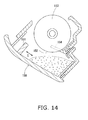
FIG.14 illustrates an exemplary air conditioner of the type. In the air conditioner, adust box 150 houses astrip compression plate 151. Thestrip compression plate 151 is configured to compress dust within thedust box 150. In this case, a large volume of dust can be stored in thedust box 150 while being compressed. Accordingly, frequency of disposing dust can be further reduced than that in the well-know air conditioners. It should be noted inFIG. 14 thatreference numerals cleaner brush 153. According to the structure, thestrip compression plate 151 is configured to be reciprocated for compressing dust within thedust box 150 in a direction of Arrow C depicted inFIG. 14 . Therefore, chances are high that dust scatters within thedust box 150 in response to large motion of thecompression plate 151. This may cause a trouble that dust leaks through thedust intake 152. - The present invention is produced for solving the aforementioned drawbacks of the well-known air conditioners. The present invention addresses a need for providing an air conditioner with an automatic air-filter cleaning function for saving time and effort of disposing dust. The air conditioner is herein configured to smoothly compress dust, removed from an air filter and contained in a dust box, while preventing the dust from leaking out of the dust box for increasing the volume of dust containable in the dust box.
- To solve the aforementioned problems, an air conditioner according to a first aspect of the present invention is an air conditioner with an automatic filter cleaning function of removing dust from an
air filter 21. The air conditioner includes adust box dust transportation section dust box dust intake dust containing section dust intake dust transportation section dust intake dust transportation section dust box dust box dust transportation section dust containing section - An air conditioner according to a second aspect of the present invention is characterized as follows. The
dust box guide wall anti-reverse wall 83, 113. Thedust intake guide wall anti-reverse wall 83, 113. Thedust transportation section guide wall anti-reverse wall 83, 113. Further, thedust transportation section dust containing section dust transportation section guide wall - An air conditioner according to a third aspect of the present invention is characterized in that dust is press-contacted with the
anti-reverse wall dust containing section - An air conditioner according to a fourth aspect of the present invention is characterized in that an interval between the
dust transportation section guide wall dust transportation section anti-reverse wall 83, 113. - An air conditioner according to a fifth aspect of the present invention is characterized in that the
anti-reverse wall 83, 113 is disposed higher than or at the same height as thedust transportation section - An air conditioner according to a sixth aspect of the present invention is characterized as follows. The air conditioner includes a
rotary brush air filter 21. Further, thedust transportation section compression rod rotary brush compression rod 86. 116 is configured to rotate about an axis arranged roughly parallel to therotary brush - An air conditioner according to a seventh aspect of the present invention is characterized as follows. The
compression rod 86 is configured to rotate in a rotational direction identical to a rotational direction of therotary brush 72. Further, theguide wall 82 is disposed on an upstream side in the rotational direction of therotary brush 72. Yet further, the anti-reverse wall 83 is disposed on a downstream side of theguide wall 82 in the rotational direction of therotary brush 72. - An air conditioner according to an eighth aspect of the present invention is characterized as follows. The
compression rod 116 is configured to rotate in a direction opposite to the rotational direction of therotary brush 102. Theguide wall 112 is disposed on a downstream side in the rotational direction of therotary brush 102. Further, theanti-reverse wall 113 is disposed on an upstream side of theguide wall 112 in the rotational direction of therotary brush 102. - An air conditioner according to a ninth aspect of the present invention is characterized as follows. The air conditioner includes a
brush cleaning member rotary brush rotary brush brush cleaning member rotary brush compression rod - An air conditioner according to a tenth aspect of the present invention is characterized in that the
guide wall 112 is formed in the vicinity of a base end portion of thebrush cleaning member 115. - An air conditioner according to an eleventh aspect of the present invention is characterized as follows. The
air filter 21 is disposed in a movable state. Therotary brush rotary brush air filter 21. Therotary brush air filter 21 during movement of theair filter 21 for removing dust from theair filter 21. Further, thecompression rod rotary brush - An air conditioner according to a twelfth aspect of the present invention is characterized as follows. The
dust transportation section dust intake dust transportation section dust box dust containing section dust containing section - An air conditioner according to a thirteenth aspect of the present invention is characterized as follows. The air conditioner includes a
rotary brush brush cleaning member rotary brush air filter 21. Thebrush cleaning member rotary brush brush cleaning member compression rod rotary brush - An air conditioner according to a fourteenth aspect of the present invention is characterized as follows. The
air filter 21 is disposed in a movable state. Therotary brush air filter 21. Further, therotary brush air filter 21 during movement of theair filter 21 for removing the dust from theair filter 21. Thecompression rod rotary brush - An air conditioner according to a fifteenth aspect of the present invention is characterized in that a surface of the
compression rod - An air conditioner according to a sixteenth aspect of the present invention is an air conditioner with an automatic filter cleaning function of removing dust from an
air filter 21. The air conditioner is characterized as follows. The air conditioner includes adust box 71 and acompression rod 91. Thedust box 71 includes adust intake 80 and adust containing section 81 configured to contain dust put therein through thedust intake 80. Thecompression rod 91 is at least partially exposed to an interior of thedust containing section 81. Thecompression rod 91 is rotatably supported by thedust box 71. Further, thedust box 71 is configured to rotationally drive thecompression rod 91 for putting dust into thedust containing section 81 and contain the dust within thedust containing section 81 in a compressed state. - An air conditioner according to a seventeenth aspect of the present invention is characterized in that a surface of the
compression rod 91 is roughened. - An air conditioner according to an eighteenth aspect of the present invention is characterized in that the
compression rod 91 includes ahelical protrusion 93a formed thereon. - An air conditioner according to a nineteenth aspect of the present invention is characterized as follows. The
air filter 21 is disposed in a movable state. The air conditioner further includes arotary brush 72. Therotary brush 72 has an axis intersecting with a moving direction of theair filter 21. Therotary brush 72 is configured to make contact with and slide along a surface of theair filter 21 during movement of theair filter 21 for removing dust from theair filter 21. Further, thecompression rod 91 is disposed roughly parallel to therotary brush 72. - According to the air conditioner of the present invention, dust is configured to be contained within the
dust containing section dust transportation section dust containing section dust containing section dust transportation section dust box dust intake - According to the air conditioner of the second aspect of the present invention, the dust, attaching to the
dust transportation section dust intake dust containing section dust transportation section guide wall dust transportation section dust intake 80. - According to the air conditioner of any of the third to fifth aspects of the present invention, dust can be reliably compressed while leakage of dust can be prevented. Simultaneously, a volume of dust containable in the air conditioner can be sufficiently ensured (i.e, increased) with a compact structure.
- Especially, according to the air conditioner of the eighth aspect of the present invention, the rotational direction A of the
rotary brush 102 and the rotational direction D of thecompression rod 116 are configured to be opposite to each other. Compression force (i.e., pressing force) can be thereby further enhanced. According to the air conditioner of the tenth aspect of the present invention, theguide wall 112 is formed in a part of the ctenoidbrush cleaning member 115, which is closer to a base end portion of thebrush cleaning member 115. Distance can be thereby reduced between thebrush cleaning member 115 and thecompression rod 116. Accordingly, moving distance of dust can be reduced and compression of dust can be smoothly achieved. - Further, according to the air conditioner of the twelfth aspect of the present invention, the dust transportation section is composed of a pair of compression rods configured to rotate opposite to each other. Dust is herein configured to be put into the dust containing section in a compressed state while being compressed between the compression rods. In this case, a compression operation can be reliably executed and accordingly dust can be further efficiently compressed.
- Further, when the surface of the
compression rod - When the air conditioner includes the
brush cleaning member rotary brush brush cleaning member compression rod rotary brush - When the
dust containing section 81 houses thecompression rod 91 in the interior thereof, a large volume of dust can be contained in thedust containing section 81 because dust is configured to be contained in the dust containing section 8 in a compressed state in conjunction with rotational driving of thecompression rod 91. Therefore, frequency of disposing dust can be reduced, and time and effort of disposing dust can be saved. Further, a moving range (movement) of thecompression rod 91 is reduced for inhibiting dust from scattering within thedust containing section 81. Dust can be thereby further smoothly compressed within thedust box 71 without leaking through thedust intake 80, compared to a well-known structure that a strip compression plate is configured to be reciprocated or a well-known structure that a strip compression plate is configured to rotate about one of longitudinal ends thereof. - When the
compression rod 91 include thehelical protrusion 93a, dust making contact with the surface of thecompression rod 91 can be consecutively transferred to either of the longitudinal ends of thecompression rod 91 while being guided by thehelical protrusion 93a. Therefore, dust can be further efficiently compressed. -
-
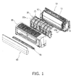
FIG.1 is an exploded oblique view of the entire structure of an air conditioner according to a first exemplary embodiment of the present invention. -
FIG.2 is a vertical cross-sectional view of the air conditioner. -
FIG.3 is an oblique view of a frame unit of the air conditioner. -
FIG.4 is an oblique view of an air filter attached to a pinion in the air conditioner. -
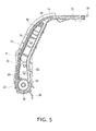
FIG.5 is a vertical cross-sectional view of a transportation section of the air conditioner. -
FIG.6 is a vertical cross-sectional view of the transportation section of the air conditioner under a condition that transportation processing is completed. -
FIG 7 is a vertical cross-sectional view of a cleaning unit of the air conditioner. -
FIG.8 is an oblique view of a rotary brush and a lid casing of the cleaning unit of the air conditioner. -
FIG.9 is an exploded oblique view of the entire structure of an air conditioner according to a second exemplary embodiment of the present invention. -
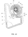
FIG.10 is a vertical cross-sectional view of a cleaning unit of the air conditioner of the second exemplary embodiment. -
FIG.11 is an exploded oblique view of the cleaning unit of the air conditioner of the second exemplary embodiment. -
FIG.12 is an oblique view of a compression rod used for the cleaning unit of the air conditioner of the second exemplary embodiment. -
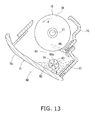
FIG.13 is a vertical cross-sectional view of another exemplary cleaning unit of the air conditioner of the present invention. -
FIG.14 is a vertical cross-sectional view of a cleaning unit of the well-known air conditioners. - Now, an air conditioner according to a specific exemplary embodiment of the present invention will be hereinafter explained with reference to figures.
FIG.1 is an exploded oblique view of the entirety of the air conditioner, whereasFIG.2 is a vertical cross-sectional view of the air conditioner. The air conditioner includes amain unit 10, afilter unit 20, anexterior casing 50, and acleaning unit 70. - The
main unit 10 includes abase frame 11. Various components are attached to thebase frame 11, including e.g., anindoor heat exchanger 12, a ventilation fan (a cross-flow fan) 13, and anelectric component box 14. Themain unit 10 is configured to inhale indoor air and execute various air conditioning operations including e.g., a cooling operation, a heating operation, and a dehumidifying operation. Thebase frame 11 includes anair outlet 15 on the bottom surface thereof. Theair outlet 15 is configured to blow the inhaled air back to the indoor after a predetermined conditioning is executed for the inhaled air. - As illustrated in
FIG.1 , thefilter unit 20 includes a pair of aright frame unit 22a and aleft frame unit 22b. Eachframe unit 22 supports anair filter 21 in a movable state (thereference numeral 22 will be hereinafter assigned to both of the frame units when distinction of right and left is not particularly made for them).FIG.3 illustrates a detailed view of theframe unit 22a, which is a front view of the right-side one of theframe units 22. Theframe unit 22 includes amain body 23 and a pair ofguide arms 24. Themain body 23 forms a lower part of theframe unit 22. Theguide arm 24 is extended from themain body 23 in an obliquely upward direction. Pinions 30 are attached to each of themain bodies 23 of the right and leftframe units pinions 30 function as a transportation section configured to transport theair filter 21 to be described. Further, a pair of alower motor 26 and anupper motor 27 is attached to the right lateral side of themain body 23 of theright frame unit 22a. Each of themotors pinions 30. Thelower motor 26 is configured to drive theair filter 21 of theright frame unit 22a illustrated inFIG.3 , whereas theupper motor 27 is configured to drive theair filter 21 of theleft frame unit 22b illustrated inFIG.1 . It should be noted that theupper motor 27 is configured to transmit a rotational output thereof to theleft frame unit 22b through atransmission shaft 38a and drive theair filter 21 of theleft frame unit 22b using a group of gears (not illustrated in the figure). It should be also noted that the front side of themain body 23 is structured as adoor section 41 in eachframe unit 22 as illustrated inFIG.3 . The lower part of thedoor section 41 is configured to pivot about the upper part thereof in a back and forth direction. - The
air filters 21 are belt-shaped filters. As illustrated inFIG.4 , eachair filter 21 includes a pair ofrack sections 35 on the back sides of the both lateral portions of aframe member 21a of theair filter 21. Therack sections 35 are configured to mesh with thepinions 30 on a one-to-one basis.FIGS.2 and5 illustrate an initial position (i.e., a normal use position) of eachair filter 21. Under the condition, the bottom end of theair filter 21 is disposed in the vicinity of thepinions 30. Further, both lateral sides of theair filter 21 are herein guided by a pair of a rightnormal guide section 31 and a leftnormal guide section 31. Thenormal guide sections 31 are formed on the insides of therespective guide arms 24 and the insides of themain body 23 in theframe unit 22. Further, theair filter 21 is configured to cover almost the entire windward part of theindoor heat exchanger 12, as similarly seen in the well-known air conditioners. - Next, the pair of the
normal guide sections 31 and a pair of foldedguide sections 32 will be explained.FIGS.2 and5 illustrate vertical cross-sectional views of the lateral part of theframe unit 22. InFIGS.2 and5 , a left side corresponds to a windward side, whereas a right side corresponds to a leeward side. In each lateral outer wall of theframe unit 22, a section ranging from a lower part to a center part has a width greater than that of an upper part. Further, each lateral outer wall of theframe unit 22 includes a bottom end portion formed in a circular-arc shape. The bottom end portion houses thepinion 30 in the interior thereof. Apartition member 33 is disposed above thepinion 30 while being separated from a corresponding lateral outer wall of theframe unit 22 at a predetermined interval. Further, eachnormal guide section 31 is formed forward of thepinion 30 while being interposed between the front outer wall of theframe unit 22 and the front surface of thepartition member 33. On the other hand, each foldedguide section 32 is formed rearward of thepinion 30 while being interposed between the rear outer wall of theframe unit 22 and the back surface of thepartition member 33. The foldedguide section 32 continues to thenormal guide section 31 in acontinuous section 34. Thecontinuous section 34 is an intermediate part (i.e., an upper part) of thenormal guide sections 31. Thus, theframe unit 22 includes a pair of thenormal guide sections 31 and a pair of the foldedguide sections 32. The pair of thenormal guide sections 31 is herein configured to retain theair filter 21 in the normal use position. On the other hand, each foldedguide section 32 continues to one of the end portions of eachnormal guide section 31. Simultaneously, each foldedguide section 32 continues to the intermediate part of eachnormal guide section 31 while being folded through acurved section 36. Further, thecurved section 36 houses thepinion 30 in the interior thereof. A rotary shaft of thepinion 30 is disposed in the horizontal direction. In other words, the rotary shaft of thepinion 30 is perpendicular to a moving direction of theair filter 21 while being extended parallel to an air filter plane. Two pinions structured above are disposed in eachframe unit 22 as a pair of aright pinion 30 and aleft pinion 30. - As described above, the
filter unit 20 is formed by coupling the pair of theright frame unit 22a and theleft frame unit 22b, each of which houses theair filter 21 and thepinions 30, and attaching themotors frame units filter unit 20 is thereby configured to drive therespective pinions 30 by means of themotors FIG.2 , thefilter unit 20 is attached to thebase frame 11. Eachframe unit 22 includes a single or plurality ofinterlock pawl pieces 28 on the upper edge thereof. The interlock pawl piece/pieces 28 are interlocked with the upper end of thebase frame 11. Further, eachframe unit 22 includes a single or plurality ofattachment pieces 29 protruded from the bottom part thereof. The attachment piece/pieces 29 is/are fixed to a part of the base frame 11 (specifically a part closer to the air outlet 15) by means of a screw/screws. As illustrated inFIG.2 , the lower section of each frame unit 22 (corresponding to a section positioned below the pinion 30) is opened to the downward in a position of the lower part of thefilter unit 20. Arotary brush 72 of thecleaning unit 70 described below is configured to clean the surface of theair filter 21 configured to move to the lower opened part. - The
exterior casing 50 is detachably attached to thefilter unit 20 while covering the outside of both themain unit 10 and thefilter unit 20. Theexterior casing 50 includes afront panel 60 on the front side thereof. Thefront panel 60 is configured to be opened and closed. Further, the pair of theright door section 41 and theleft door section 41 of thefilter unit 20 is disposed on the back side of thefront panel 60. Attachment/detachment of the pair of theright air filter 21 and theleft air filter 21 is configured to be executed through an opening/closing operation of the pair of theright door section 41 and theleft door section 41. This is because the pair of theright door section 41 and theleft door section 41 is configured to be exposed only by opening or removing thefront panel 60 without removing the entireexterior casing 50. - As illustrated in
FIGS. 2 and7 , thecleaning unit 70 includes adust box 71 and therotary brush 72. Thedust box 71 is detachably attached to theexterior casing 50. Thedust box 71 is configured to contain dust removed from theair filter 21. Therotary brush 72 is configured to make contact with and slide along the surfaces of theair filters 21 for scraping away the dust attaching to the air filters 21. - As illustrated in
FIG.7 , thedust box 71 is formed in a transversely elongated box shape by the combination of amain casing 74 and alid casing 75 attached to themain casing 74. Further, thedust box 71 is disposed below thefilter unit 20 under a condition that an upper openedsection 76 is opposed to a lower opened section of thefilter unit 20. - As illustrated in
FIGS.7 and8 , therotary brush 72 includes arotary shaft 77 and a pair ofbrush fur sections 78. Therotary shaft 77 is rotatably supported by thelid casing 75 of thedust box 71. Thebrush fur sections 78 are embedded into the outer peripheral surface of therotary shaft 77. Further, therotary brush 72 is contained within thedust box 71 while being disposed along a longitudinal direction of thedust box 71. Thebrush fur sections 78 are herein partially exposed out of the upper openedsection 76. Therotary brush 72 is disposed under a condition that the rotary shaft 77 (i.e., an axis) intersects with a moving direction of the air filters 21. It should be noted that agear 79 is attached to one of the distal ends of therotary shaft 77 of therotary brush 72. Therotary brush 72 is configured to rotate about therotary shaft 77 when thegear 79 is rotationally driven by a driving section such as a driving motor (not illustrated in the figure). - As illustrated in
FIG.7 , thedust box 71 includes adust containing section 81. Thedust containing section 81 is configured to contain dust put therein through adust intake 80 positioned below therotary brush 72. Thedust intake 80 is segmented and formed between the front end (i.e., the distal end) of a plate-shapedguide wall 82 and the front end (i.e., the distal end) of a plate-shaped anti-reverse wall 83, while being disposed along therotary brush 72. Theguide wall 82 is herein protruded from themain casing 74, whereas the anti-reverse wall 83 is protruded from thelid casing 75. - As illustrated in
FIG.7 , theguide wall 82 is positioned below therotary brush 72 while being disposed along therotary brush 72. Theguide wall 82 is slanted downwards from the base end thereof to the front end thereof (i.e., slanted downwards form front to rear). Further, the front end of theguide wall 82 is bent downward. On the other hand, the anti-reverse wall 83 is positioned below therotary brush 72 while being disposed along therotary brush 72, as illustrated inFIG.7 . The anti-reverse wall 83 is slanted downwards from the base end thereof to the front end thereof (i.e., slanted downwards from rear to front). In other words, theguide wall 82 and the anti-reverse wall 83 are disposed in a roughly V-shape in a side view. A clearance is thereby produced between the bottom portion of theguide wall 82 and the bottom portion of the anti-reverse wall 83 (i.e., the front end of theguide wall 82 and the front end of the anti-reverse wall 83). The clearance herein functions as thedust intake 80. Further, the lower space of themain casing 74 is segmented by theguide wall 82 and the anti-reverse wall 83. The lower space herein functions as thedust containing section 81. - Further, the
dust box 71 houses abrush cleaning member 85 and acompression rod 86. Thebrush cleaning member 85 is configured to scrape away and drop dust attaching to therotary brush 72 towards thedust intake 80. Thecompression rod 86 allows thedust containing section 81 to contain dust put therein through thedust intake 80 in a compressed state. - As illustrated in
FIGS. 7 and8 , thebrush cleaning member 85 is attached to thelid casing 75. Further, thebrush cleaning member 85 has a ctenoid front end. The front end of thebrush cleaning member 85 is positioned below therotary brush 72, while being disposed along a longitudinal direction of therotary brush 72. The front end of thebrush cleaning member 85 is slanted upwards from rear to front. The ctenoid front end is meshed with thebrush fur sections 78 of therotary brush 72. Thebrush cleaning member 85 is accordingly configured to scrape away and drop dust attaching to thebrush fur sections 78 in conjunction with rotation of the rotary brush 72 (i.e., counterclockwise rotation depicted with Arrow A inFIG.7 ). - As illustrated in
FIG.7 , thecompression rod 86 includes arotary shaft 87 and afriction member 88. Therotary shaft 87 is rotatably supported by themain casing 74. Thefriction member 88 is attached to the outer peripheral surface of therotary shaft 87. The surface of thefriction member 88 is roughened. Further, thecompression rod 86 is positioned below thebrush cleaning member 85 while being roughly parallel to therotary shaft 72. Further, thecompression rod 86 is disposed in or in the vicinity of thedust intake 80. It should be noted that a gear (not illustrated in the figure) is attached to one of the distal ends of therotary shaft 87 of thecompression rod 86. Thecompression rod 86 is configured to rotate about the rotary shaft 87 (i.e., rotate in a counterclockwise direction depicted with Arrow B inFIG.7 ) when the gear is rotationally driven by a driving section such as a driving motor (not illustrated in the figure). In this case, a single driving section may be shared by therotary brush 72 and thecompression rod 86 for rotationally driving therotary brush 72 and thecompression rod 86 in conjunction with each other. It should be also noted that theaforementioned friction member 88 is used for forming the surface of thecompression rod 86 in a roughened condition. Alternatively, the surface of thecompression rod 86 can be formed in a roughed condition by forming a convexo-concave or a groove on the surface of thecompression rod 86 made of a synthetic resin. - Further, the
compression rod 86 is disposed between the front end of theguide wall 82 and the front end of the anti-reverse wall 83. Further, theguide wall 82 is disposed on a side positioned in a direction that the surface of thecompression rod 86 approaches to thedust containing section 81. On the other hand, the anti-reverse wall 83 is disposed on a side positioned in a direction that the surface of thecompression rod 86 separates away from thedust containing section 81. Further, thecompression rod 86 is disposed under a condition that an interval between the surface of thecompression rod 86 and the front end of theguide wall 82 is greater than an interval between the surface of thecompression rod 86 to the front end of the anti-reverse wall 83. When dust is scraped away by therotary brush 72 and attaches to thecompression rod 86, the aforementioned structure is configured to smoothly guide the dust into thedust containing section 81 through the clearance produced between the surface of thecompression rod 86 and the front end of theguide wall 82. Further, the structure is configured to prevent dust left attaching to thecompression rod 86 from leaking through thedust intake 80. In addition, the surface of thecompression rod 86 is roughened. Pressing force is thereby further increased in guiding dust into thedust containing section 81 through the clearance produced between the surface of thecompression rod 86 and the front end of theguide wall 82. In other words, a dust containing operation can be reliably executed. - The aforementioned air conditioner is configured to execute an air conditioning operation under a condition that the
air filters 21 are set to be in normal positions illustrated inFIGS.2 and5 . The air conditioner is then configured to execute an automatic cleaning operation for theair filters 21 when the air conditioning operation is deactivated or more specifically when the air conditioning operation is deactivated under a predetermined condition is satisfied (e.g., a predetermined period of time has been elapsed). The procedure of the automatic cleaning operation will be hereinafter explained with reference toFIGS.5 and6 . It should be noted in a state ofFIG.5 (i.e., a normal operation state) that the lower end of theair filter 21 will be hereinafter referred to as "a front end" whereas the upper end of theair filter 21 will be hereinafter referred to as "a rear end" for the sake of convenience in explanation. - First, the
respective motors pinions 30 from the state illustrated inFIG.5 . Simultaneously, therotary brush 72 and thecompression rod 86 of thecleaning unit 70 are rotationally driven. Accordingly, theair filters 21 start moving because therack sections 35 of theair filters 21 are meshed with thepinions 30. The front end of eachair filter 21 moves down, and is then turned up while passing through the surroundings of thepinions 30. The front end of eachair filter 21 thus moves up on the back surface side (i.e., a back side in an air flow direction). In this case, therotary brush 72 is rotated in a direction opposite to the rotational direction of the pinion 30 (i.e., a counterclockwise direction illustrated in Arrow A inFIG.7 ). Accordingly, therotary brush 72 scrapes way dust attaching to theair filters 21 of the moving states while sliding along the surface of the air filters 21. When reaching thecontinuous section 34 formed in the intermediate part of thenormal guide sections 31, the front end of eachair filter 21 is guided from thecontinuous section 34 to the upper end of the normal guide section, i.e., a section where the rear end of theair filter 21 is positioned in the initial state. Eachair filter 21 is thus moved to the back surface side. It should be noted that the position of thecontinuous section 34 is set in relation to the length of eachair filter 21. In other words, the front end of eachair filter 21 is herein configured to be guided to the upper end of the normal guide section after the rear end of eachair filter 21 passes through thecontinuous section 34. Thecleaning unit 70 executes cleaning of theair filters 21 in the transportation processing. When thecleaning unit 70 completes cleaning of the component, rotation of thepinion 30 and rotational driving of therotary brush 72 are deactivated. The outbound cleaning operation is thus completed with the aforementioned configuration. Next, the inbound cleaning operation will be executed. In this case, thepinions 30 are configured to be rotated in a direction opposite to the rotational direction in the outbound cleaning operation. Theair filter 21 is thereby transported from the foldedguide section 32 to thenormal guide sections 31. Thecleaning unit 70 executes cleaning of theair filter 21 in the transportation processing. It should be noted that in the outbound cleaning operation, therotary brush 72 is configured to be rotationally driven faster than the transportation speed of theair filters 21 or rotational driving of therotary brush 72 is configured to be suspended. - The
rotary brush 72 thus scrapes away dust in the aforementioned cleaning operation, and the scraped dust partially drops on the top surface of theguide wall 82 of thedust box 71. The dust is then guided to thedust intake 80 along the slope of theguide wall 82. The dust is transported into thedust containing section 81 through thedust intake 80. On the other hand, dust left attaching to therotary brush 72 without dropping from therotary brush 72 is scraped by thebrush cleaning member 85. The scraped dust is then transported into thedust containing section 81 through thedust intake 80. - The dust, dropping on the top surface of the
guide wall 82, is herein mainly cloud-like dust having a large size and a low density. Therefore, the dust is compressed between thecompression rod 86 and the front end of theguide wall 82, and the compressed dust is transported into thedust containing section 81. In this case, thecompression rod 86 is rotated (i.e., in a counterclockwise direction depicted with Arrow B inFIG.7 ) within thedust containing section 81 of thedust box 71. Therefore, rotation of thefriction member 88 consecutively transports dust, filled up to the vicinity of thedust intake 80 within thedust containing section 81, to the rearward (i.e., to the back side of the anti-reverse wall 83). The dust is finally press-contacted with the anti-reverse wall 83 by means of rotation of thefriction member 88. The dust is thus contained within thedust containing section 81 in a compressed state. In this case, thecompression rod 86 is only rotated about therotary shaft 87 thereof. The moving range (i.e., movement) of thecompression rod 86 is thereby reduced to a small extent. Therefore, scattering of dust can be inhibited within thedust containing sections 81. Further, thecompression rod 86 can further smoothly compress dust within thedust box 71 without allowing dust from leaking through thedust intake 80, compared to a structure that a strip compression plate is configured to be reciprocated. Further, when thedust containing section 81 is filled with dust, thedust box 71 is removed from theexterior casing 50 for disposing the dust stored in thedust box 71. In this case, thedust containing section 81 can contain a large volume of dust by containing the dust therein in a compressed state. Therefore, frequency of disposing dust can be reduced. Accordingly, time and effort of disposing dust can be saved. - Overall, the aforementioned air conditioner is of a type having an automatic filter cleaning function and includes the
dust box 71 configured to contain dust removed from theair filter 21. The air conditioner is characterized as follows. Thedust box 71 herein includes thedust intake 80 and thedust containing section 81 configured to contain dust put therein through thedust intake 80. Further, thedust box 71 supports a dust transportation section (i.e., the compression rod 86) in or in the vicinity of thedust intake 80 while allowing thedust transportation section 86 to rotate. Further the dust box is configured to rotationally drive the dust transportation section (i.e., the compression rod 86) for containing dust within thedust containing section 81 in a compressed state. - Next, an air conditioner according to a second exemplary embodiment of the present invention will be hereinafter explained. As illustrated in
FIGS.9 to 12 , the air conditioner of the second exemplary embodiment includes acleaning unit 100 as a modified cleaning unit. As illustrated inFIG.9 , amain unit 10, afilter unit 20, anexterior casing 50, and afront panel 60 are approximately the same as those in the first exemplary embodiment. Therefore, when a component of the second exemplary embodiment has a function identical to that of a component of the first exemplary embodiment, a reference numeral assigned to the member of the first exemplary embodiment is also assigned to the member of the first exemplary embodiment. Explanation of component will be hereinafter omitted for the sake of brevity. Thecleaning unit 100 is detachably attached to theexterior casing 50. Thecleaning unit 100 includes adust box 101 and arotary brush 102. Thedust box 101 is configured to contain dust removed fromair filters 21. Therotary brush 102 is configured to make contact with and slide along the surface of theair filters 21 for scraping away dust attaching to the air filters 21. - As illustrated in
FIG.10 , thedust box 101 is formed in a transversely elongated box shape by the combination of amain casing 104 and alid casing 105 attached to themain casing 104. Further, thedust box 101 is disposed below thefilter unit 20 under a condition that an upper openedsection 106 thereof is opposed to a lower opened section of thefilter unit 20. Unlike the exemplary embodiment illustrated inFIG.7 , thelid casing 105 is herein disposed on the front side of the air conditioner, whereas themain casing 104 is disposed on the back side of the air conditioner. Further, themain casing 104 supports the axis of therotary brush 102 as illustrated inFIG.11 . On the other hand, thelid casing 105 supports the axis of acompression rod 116. As illustrated inFIGS.10 and11 , themain casing 104 is composed of anupper casing member 118, alower casing member 119, and abrush cleaning member 115. Thebrush cleaning member 115 is attached to theupper casing member 118. - The
rotary brush 102 includes arotary shaft 107 and a pair ofbrush fur sections 108. Therotary shaft 107 is rotatably supported by themain casing 104 of thedust box 101. Thebrush fur sections 108 are embedded into the outer peripheral surface of therotary shaft 107. Further, therotary brush 102 is contained within thedust box 101 while being disposed along a longitudinal direction of thedust box 101. Thebrush fur sections 108 are herein partially exposed out of the upper openedsection 106. Therotary brush 102 is disposed under a condition that the rotary shaft 107 (i.e., an axis) intersects (perpendicularly) with a moving direction of the air filters 21. It should be noted that a gear (not illustrated in the figure) is attached to one of the distal ends of therotary shaft 107 of therotary brush 102. Therotary brush 102 is configured to rotate about therotary shaft 107 when the gear is rotationally driven by a driving section such as a driving motor (not illustrated in the figure). Further, agear 109 is attached to an axial intermediate part of therotary shaft 107, as illustrated inFIG.11 . Thegear 109 is configured to rotationally drive thecompression rod 116, as described below. - As illustrated in
FIG.10 , thedust box 101 includes adust containing section 111. Thedust containing section 111 is positioned below therotary brush 102. Thedust containing section 111 is configured to contain dust put therein through adust intake 110. Thebrush cleaning member 115 of themain casing 104 includes aguide wall 112 formed in a part thereof, which is closer to the base end thereof attached to theupper casing member 118. Further, thelid casing 105 includes ananti-reverse wall 113 formed thereon. Contrary to the exemplary embodiment illustrated inFIG.7 , theanti-reverse wall 113 is herein disposed on the front side of the air conditioner, whereas theguide wall 112 is disposed on the back side of the air conditioner. Further, thedust intake 110 is segmented and formed between theguide wall 112 and theanti-reverse wall 113. Yet further, thecompression rod 116 is disposed along therotary brush 102 while being opposed to theguide wall 112 and theanti-reverse wall 113 within thedust intake 110. Theanti-reverse wall 113 is disposed above the axis of thecompression rod 116. In other words, theanti-reverse wall 113 is positioned higher than thecompression rod 116. - The
brush cleaning member 115 of thedust box 101 is configured to scrape away and drop dust attaching to therotary brush 102 to thedust intake 110. Further, thecompression rod 116 is configured to function as a dust transportation section. When dust is removed by thebrush cleaning member 115 and drops through thedust intake 110, the dust transportation section is configured to put the dust into thedust containing section 111 in a compressed state. - As illustrated in
FIGS.10 and11 , thebrush cleaning member 115 is attached to theupper casing member 118 of themain casing 104. Further, thebrush cleaning member 115 has a ctenoid front end. The front end is slanted upwards from rear to front. The front end is positioned below therotary brush 102 while being disposed along a longitudinal direction of therotary brush 102. The ctenoid front end is thereby meshed with thebrush fur sections 108 of therotary brush 102. Thebrush cleaning member 115 is accordingly configured to scrape away and drop dust attaching to thebrush fur sections 108 in conjunction with rotation of the rotary brush 102 (i.e., counterclockwise rotation depicted with Arrow A inFIG.10 ). - As illustrated in
FIG.12 , thecompression rod 116 includes arotary shaft 117 rotatably supported by thelid casing 105. Therotary shaft 117 includes awavy protrusion 120 on the outer peripheral surface thereof. Theprotrusion 120 is formed on radial opposed parts of the outer peripheral surface of therotary shaft 117. Each of the radial opposed parts has an area roughly one-fourth of the entire area of the outer peripheral surface of therotary shaft 117. On the other hand, no change is made for the rest of the outer peripheral surface of therotary shaft 117, i.e., the remaining radial opposed parts having an area roughly one-fourth of the entire area of the outer peripheral surface of therotary shaft 117. In short, thewavy protrusion 120 is formed on the top and bottom parts of the outer peripheral surface of therotary shaft 117, whereas no change is made for the right and left parts of the outer peripheral surface of therotary shaft 117. As illustrated inFIG.11 , theprotrusion 120 is axially segmented into halves at the axial center of therotary shaft 117. One of the axial halves of theprotrusion 120 is phase-displaced at an angle of 90 degrees with respect to the other of the axial halves of theprotrusion 120. Theprotrusion 120 is thereby configured to disperse the maximum torque to be produced in moving and compressing dust. This achieves reduction in driving force to be required. Thecompression rod 116 is positioned below thebrush cleaning member 115 while being disposed roughly parallel to therotary brush 102. Thecompression rod 116 is also disposed in thedust intake 110. Further, agear 121 is attached to the axial center part of therotary shaft 117 of thecompression rod 116. Thegear 121 is meshed with thegear 109 of therotary brush 102. Thecompression rod 116 is configured to rotate about the rotary shaft 117 (in a clockwise direction depicted with Arrow D inFIG. 10 ) when therotary brush 102 is rotationally driven by means of a driving section such as a driving motor (not illustrated in the figure). In this case, thecompression rod 116 is configured to be rotationally driven in a direction opposite to rotational direction of therotary brush 102. - A remarkable difference between the first and second exemplary embodiments is that the
rotary brush 102 and thecompression rod 116 are configured to rotate opposite to each other in the second exemplary embodiment. Because of the configuration, the air conditioner of the second exemplary embodiment has the structure that theanti-reverse wall 113 is disposed on the front side of the air conditioner whereas theguide wall 112 is disposed on the back side of the air conditioner. It should be noted that the air conditioner of the second exemplary embodiment also has the structure that an interval between the surface of thecompression rod 116 and the front end of theguide wall 112 is set to be greater than an interval between the surface of thecompression rod 116 and the front end of theanti-reverse wall 113. When an automatic cleaning operation is executed for theair filters 21 in the air conditioner according to the second exemplary embodiment, dust existing between thecompression rod 116 and therotary brush 102 is transported towards thedust intake 110 in conjunction with rotation of thecompression rod 116 and therotary brush 102. The dust is then scraped by theprotrusion 120 of thecompression rod 116. The dust is thereby transported into thedust containing section 111 from thedust intake 110, as indicated with Arrow E inFIG. 10 . Thus, dust is scraped by thecompression rod 116 along a direction that dust is transported by the rotary brush 102 (i.e., in a direction identical to the dust transportation direction). Therefore, dust can be smoothly removed. - Especially, dust removed from the
rotary brush 102 is compressed while moving in the direction of gravitational force. Therefore, dust can be discharged in a natural flow. Further, transportation of dust and compression of dust are executed by a single component (i.e., the compression rod 116). Therefore, dust can be compressed in a limited space with a simple structure. In addition, thecompression rod 116 includes thewavy protrusion 120. Therefore, compression force (i.e., pressing force) can be enhanced. Further, the rotational direction A of therotary brush 102 and the rotational direction D of thecompression rod 116 are configured to be opposite to each other. Therefore, the compression force (pressing force) can be further enhanced. Yet further, distance between therotary brush 102 and the guide wall 112 (and distance between therotary brush 102 and the compression rod 116) can be shorter than that in the aforementioned first exemplary embodiment. Accordingly, scattering and swirling of dust (cloud-like dust) can be prevented. Further, theguide wall 112 is formed on a part of the ctenoidbrush cleaning member 115, which is closer to the base end of thebrush cleaning member 115. Distance can be thereby reduced between thebrush cleaning member 115 and thecompression rod 116. In other words, moving distance of dust is reduced. Therefore, dust can be smoothly compressed. -
FIG.13 illustrates acleaning unit 90 of an air conditioner according to another exemplary embodiment. Thecleaning unit 90 does not include theaforementioned guide wall 82 and the aforementioned anti-reverse wall 83. In thecleaning unit 90, acompression rod 91 is disposed within adust containing section 81 of adust box 71 and entirety of the upper opened part of adust containing section 81 is configured to function as adust intake 80. - The
compression rod 91 includes arotary shaft 92 and afriction member 93. Therotary shaft 92 is rotatably supported by amain casing 74. Thefriction member 93 is attached to the outer peripheral surface of therotary shaft 92. The surface of thefriction member 93 is roughened. Further, thecompression rod 91 is positioned below abrush cleaning member 85 while being disposed roughly parallel to arotary brush 72. It should be noted that a gear (not illustrated in the figure) is attached to one of the distal ends of therotary shaft 92 of thecompression rod 91. Thecompression rod 91 is configured to rotate about the rotary shaft 92 (i.e., rotate in a counterclockwise direction depicted with Arrow B inFIG.9 ) when the gear is rotationally driven by a driving section such as a driving motor (not illustrated in the figure). - The
friction member 93 of thecompression rod 91 includes ahelical protrusion 93a almost entirely longitudinally formed on the outer peripheral surface thereof. Thecompression rod 91 is configured to consecutively transport dust making contact with thefriction member 93 to either of the longitudinal ends thereof while guiding the dust by thehelical protrusion 93a in order to contain dust within thedust containing section 81 in a compressed state. In this case, thecompression rod 91 is also configured to only rotate about therotary shaft 92 thereof The moving range (i.e., movement) of thecompression rod 91 is thereby reduced to a small extent. Scattering of dust can be accordingly inhibited within thedust containing section 81. Further, dust can be smoothly compressed without leaking out of thedust box 71. It should be noted that the other structures in the present exemplary embodiment are identical to those in the exemplary embodiment illustrated inFIG.7 . Therefore, when a member illustrated inFIG. 13 has a function identical to that of a member of the aforementioned exemplary embodiment illustrated inFIG.7 , a reference numeral assigned to the member inFIG.7 is also assigned to the member inFIG. 13 . - Overall, the air conditioner, including the
cleaning unit 90, is of a type having an automatic filter cleaning function and includes thedust box 71 configured to contain dust removed from theair filter 21. The air conditioner is characterized as follows. Thedust box 71 includes thedust intake 80 and thedust containing section 81 configured to contain the dust put therein through thedust intake 80. Further, thedust box 71 rotatably supports thecompression rod 91 while allowing thecompression rod 91 to rotate under a condition that thecompression rod 91 is at least partially exposed to the interior of thedust containing section 81. Yet further, thedust box 71 is configured to rotationally drive thecompression rod 91 for containing dust within thedust containing section 81 in a compressed state. - The exemplary embodiments of the present invention have been specifically explained above. However, the present invention is not limited to the aforementioned exemplary embodiments. A variety of changes can be made for the aforementioned exemplary embodiments without departing from the scope of the present invention.
- For example, the aforementioned dust transportation section may be composed of a pair of compression rods disposed in (or in the vicinity of) a dust intake. The pair of compression rods is herein configured to rotate opposite to each other. In other words, when dust is removed by a rotary brush and drops on the pair of compression rods, the pair of compression rods is configured to compress the dust and put the dust into a dust containing section in a compressed state. Further, in the aforementioned exemplary embodiment illustrated in
FIG.13 , thecompression rod 91 is entirely disposed within thedust containing section 81. However, the present invention may adopt an arrangement that only a part of thecompression rod 91 is exposed to the interior of thedust containing section 81. Further, the present invention is not limited to the air conditioners of a type configured to inhale indoor air and execute a cooling operation, a heating operation, and a dehumidifying operation. For example, the present invention can be applied to the air conditioners having only an air cleaning function of trapping dust contained in the indoor air. Further, the moving section configured to move air filters is not limited to be of the aforementioned loop type, and may be of a winding type. -
- 21
- Air filter
- 71, 101
- Dust box
- 72, 102
- Rotary brush
- 80, 110
- Dust intake
- 81, 111
- Dust containing section
- 82, 112
- Guide wall
- 83, 13
- Anti-reverse wall
- 85, 15
- Brush cleaning member
- 86, 91, 106
- Compression rod
- 93a
- Helical protrusion
<Patent Document 1>
Japan Laid-open Patent Application Publication No.JP-A-2004-347246
Claims (19)
- An air conditioner with an automatic filter cleaning function of removing dust from an air filter (21), comprising:a dust box (71) (101) including a dust intake (80) (110) and a dust containing section (81) (111) configured to contain dust put therein through the dust intake (80) (110); anda dust transportation section (86) (116) disposed in or in the vicinity of the dust intake (80) (110), the dust transportation section (86) (116) rotatably supported by the dust box (71) (101),wherein the dust box (71) (101) is configured to rotationally drive the dust transportation section (86) (116) for containing dust within the dust containing section (81) (111) in a compressed state.
- The air conditioner according to claim 1,
wherein the dust box (71) (101) includes a guide wall (82) (112) and an anti-reverse wall (83) (113),
the dust intake (80) (110) is segmented and formed between a distal end of the guide wall (82) (112) and a distal end of the anti-reverse wall (83) (113), and
the dust transportation section (86) (116) is disposed between the guide wall (82) (112) and the anti-reverse wall (83) (113), the dust transportation section (86) (116) being configured to transport dust into the dust containing section (81) (111) through a clearance produced between the dust transportation section (86) (116) and the guide wall (82) (112). - The air conditioner according to claim 2,
wherein dust is press-contacted with the anti-reverse wall (83) (113) after the dust is transported into the dust containing section (81) (111). - The air conditioner according to one of claims 2 and 3, wherein an interval between the dust transportation section (86) (116) and the distal end of the guide wall (82) (112) is set to be greater than an interval between the dust transportation section (86) (116) and the distal end of the anti-reverse wall (83) (113).
- The air conditioner according to one of claims 2 to 4, wherein the anti-reverse wall (83) (113) is disposed higher than or at the same height as the dust transportation section (86) (116).
- The air conditioner according to one of claims 1 to 5, further comprising:a rotary brush (72) (102) configured to remove dust from the air filter (21),wherein the dust transportation section (86) (116) is composed of a compression rod (86) (116) disposed below the rotary brush (72) (102), the compression rod (86) (116) being configured to rotate about an axis arranged roughly parallel to the rotary brush (72) (102).
- The air conditioner according to claim 6,
wherein the compression rod (86) is configured to rotate in a rotational direction identical to a rotational direction of the rotary brush (72),
the guide wall (82) is disposed on an upstream side in the rotational direction of the rotary brush (72), and
the anti-reverse wall (83) is disposed on a downstream side of the guide wall (82) in the rotational direction of the rotary brush (72). - The air conditioner according to claim 6,
wherein the compression rod (116) is configured to rotate in a direction opposite to the rotational direction of the rotary brush (102),
the guide wall (112) is disposed on a downstream side in the rotational direction of the rotary brush (102), and
the anti-reverse wall (113) is disposed on an upstream side of the guide wall (112) in the rotational direction of the rotary brush (102). - The air conditioner according to one of claims 6 to 8, further comprising:a brush cleaning member (85) (115) configured to remove dust attaching to the rotary brush (72) (102) from the rotary brush (72) (102),wherein the brush cleaning member (85) (115) is disposed between the rotary brush (72) (102) and the compression rod (86) (116).
- The air conditioner according to claim 9, wherein the guide wall (112) is formed in the vicinity of a base end portion of the brush cleaning member (115).
- The air conditioner according to one of claims 6 to 10,
wherein the air filter (21) is disposed in a movable state,
the rotary brush (72) (102) is disposed under a condition that the axis of the rotary brush (72) (102) intersects with a moving direction of the air filter (21), the rotary brush (72) (102) being configured to make contact with and slide along a surface of the air filter (21) during movement of the air filter (21) for removing dust from the air filter (21), and
the compression rod (86) (116) is disposed roughly parallel to the rotary brush (72) (102). - The air conditioner according to claim 1,
wherein the dust transportation section is disposed in or in the vicinity of the dust intake (80) (110), the dust transportation section including a pair of compression rods configured to rotate opposite to each other, and
the dust box (71) (101) is configured to rotationally drive the compression rods for putting dust into the dust containing section (81) (111) through a clearance produced between the compression rods and contain the dust within the dust containing section (81) (111) in a compressed state. - The air conditioner according to claim 12, further comprising:a rotary brush (72) (102) configured to remove dust from the air filter (21); anda brush cleaning member (85) (115) configured to remove dust attaching to the rotary brush (72) (102),wherein the brush cleaning member (85) (115) is disposed between the compression rod (86) (116) and the rotary brush (72) (102).
- The air conditioner according to claim 13,
wherein the air filter (21) is disposed in a movable state,
the rotary brush (72) (102) has an axis intersecting with a moving direction of the air filter (21), the rotary brush (72) (102) being configured to make contact with and slide along a surface of the air filter (21) during movement of the air filter (21) for removing dust from the air filter (21), and
the compression rod (86) (116) is disposed roughly parallel to the rotary brush (72) (102). - The air conditioner according to one of claims 6 to 14, wherein a surface of the compression rod (86) (116) is roughened.
- An air conditioner with an automatic filter cleaning function of removing dust from an air filter (21), comprising:a dust box (71) including a dust intake (80) and a dust containing section (81) configured to contain dust put therein through the dust intake (80); anda compression rod (91) at least partially exposed to an interior of the dust containing section (81), the compression rod (11) rotatably supported by the dust box (71),wherein the dust box (71) is configured to rotationally drive the compression rod (91) for putting dust into the dust containing section (81) and contain the dust within the dust containing section (81) in a compressed state.
- The air conditioner according to claim 16, wherein a surface of the compression rod (91) is roughened.
- The air conditioner according to claim 17, wherein the compression rod (91) includes a helical protrusion (93a) formed thereon.
- The air conditioner according to one of claims 16 to 18,
wherein the air filter (21) is disposed in a movable state,
the air conditioner further includes a rotary brush (72), the rotary brush (72) having an axis intersecting with a moving direction of the air filter (21), the rotary brush (72) being configured to make contact with and slide along a surface of the air filter (21) during movement of the air filter (21) for removing dust from the air filter (21), and
the compression rod (91) is disposed roughly parallel to the rotary brush (72).
Applications Claiming Priority (3)
| Application Number | Priority Date | Filing Date | Title |
|---|---|---|---|
| JP2008048738 | 2008-02-28 | ||
| JP2008231532A JP4433079B2 (en) | 2008-02-28 | 2008-09-09 | Air conditioner |
| PCT/JP2009/000834 WO2009107377A1 (en) | 2008-02-28 | 2009-02-25 | Air conditioning apparatus |
Publications (2)
| Publication Number | Publication Date |
|---|---|
| EP2267375A1 true EP2267375A1 (en) | 2010-12-29 |
| EP2267375A4 EP2267375A4 (en) | 2013-12-18 |
Family
ID=41015784
Family Applications (1)
| Application Number | Title | Priority Date | Filing Date |
|---|---|---|---|
| EP09715163.3A Withdrawn EP2267375A4 (en) | 2008-02-28 | 2009-02-25 | AIR CONDITIONING DEVICE |
Country Status (4)
| Country | Link |
|---|---|
| EP (1) | EP2267375A4 (en) |
| JP (1) | JP4433079B2 (en) |
| CN (5) | CN103292451B (en) |
| WO (1) | WO2009107377A1 (en) |
Cited By (1)
| Publication number | Priority date | Publication date | Assignee | Title |
|---|---|---|---|---|
| EP3091303A1 (en) * | 2015-05-04 | 2016-11-09 | Samsung Electronics Co., Ltd | Filter cleaning device and air conditioner having the same |
Families Citing this family (14)
| Publication number | Priority date | Publication date | Assignee | Title |
|---|---|---|---|---|
| JP5447934B2 (en) * | 2009-07-29 | 2014-03-19 | 株式会社コーワ | Air conditioner cleaning device and air conditioner |
| JP5737737B2 (en) * | 2009-10-30 | 2015-06-17 | 株式会社コーワ | Air filter cleaning mechanism and projector device |
| JP5679265B2 (en) * | 2010-06-08 | 2015-03-04 | 株式会社コーワ | Air filter cleaning mechanism and projector device |
| JP5919512B2 (en) * | 2012-10-02 | 2016-05-18 | パナソニックIpマネジメント株式会社 | Air conditioner |
| JP6506989B2 (en) * | 2015-03-03 | 2019-04-24 | シャープ株式会社 | Air cleaning mechanism |
| TR201617251T1 (en) * | 2015-03-27 | 2017-04-21 | Mitsubishi Electric Corp | Air conditioner indoor unit. |
| JP6725213B2 (en) * | 2015-05-20 | 2020-07-15 | シャープ株式会社 | Air cleaner |
| EP3276277B1 (en) * | 2016-07-28 | 2020-04-08 | Daikin Industries, Ltd. | Filter cleaning device for an air conditioner and air conditioner having such filter cleaning device |
| JP6754944B2 (en) * | 2016-08-24 | 2020-09-16 | パナソニックIpマネジメント株式会社 | Air conditioner |
| JP2019152416A (en) * | 2018-03-06 | 2019-09-12 | 日本電産サンキョー株式会社 | Filter cleaning device of air conditioner |
| CN112815399B (en) * | 2019-11-18 | 2025-02-07 | 广东美的制冷设备有限公司 | Air conditioner indoor unit and air conditioner |
| JP7461257B2 (en) * | 2020-09-08 | 2024-04-03 | シャープ株式会社 | Dust collection containers, filter cleaning devices, and air conditioners |
| CN115930305B (en) * | 2022-12-05 | 2023-07-21 | 株洲桓基电气股份有限公司 | Environment-friendly water circulation movable air conditioner |
| CN118807337B (en) * | 2024-06-26 | 2025-04-22 | 河北航研制冷设备有限公司 | Air source heat pump two-in-one supply comfortable device |
Family Cites Families (13)
| Publication number | Priority date | Publication date | Assignee | Title |
|---|---|---|---|---|
| JPS4837558U (en) * | 1971-09-08 | 1973-05-08 | ||
| JPS6053199A (en) * | 1983-09-02 | 1985-03-26 | 松下電器産業株式会社 | clothes dryer |
| JPS62160221U (en) * | 1986-03-31 | 1987-10-12 | ||
| JPH0674521A (en) * | 1992-08-21 | 1994-03-15 | Matsushita Electric Ind Co Ltd | Air conditioner |
| JP4804607B2 (en) * | 1999-12-14 | 2011-11-02 | パナソニック株式会社 | Dust remover |
| JP2002005504A (en) * | 2000-06-20 | 2002-01-09 | Fujitsu General Ltd | Air conditioner |
| JP4110375B2 (en) * | 2002-06-27 | 2008-07-02 | 株式会社富士通ゼネラル | Air conditioner |
| CN100339647C (en) * | 2003-03-04 | 2007-09-26 | 松下电器产业株式会社 | Air conditioner having indoor unit with automatic air filter celaning function |
| JP4296840B2 (en) * | 2003-05-23 | 2009-07-15 | 株式会社富士通ゼネラル | Air conditioner |
| CN1755202A (en) * | 2004-09-29 | 2006-04-05 | 乐金电子(天津)电器有限公司 | Air conditioner indoor unit with improving air purifying function |
| CN101655264B (en) * | 2005-07-04 | 2012-07-04 | 三菱重工业株式会社 | Indoor unit and air conditioner |
| WO2007066693A1 (en) * | 2005-12-06 | 2007-06-14 | Toshiba Carrier Corporation | Indoor unit for air conditioner |
| CN101070986A (en) * | 2007-04-17 | 2007-11-14 | 海尔集团公司 | Air conditioner filtering screen dust-cleaning method and device, and airconditioner with filtering screen dust-cleaning device |
-
2008
- 2008-09-09 JP JP2008231532A patent/JP4433079B2/en active Active
-
2009
- 2009-02-25 CN CN201310187444.6A patent/CN103292451B/en not_active Expired - Fee Related
- 2009-02-25 CN CN201210555021.0A patent/CN103032946B/en not_active Expired - Fee Related
- 2009-02-25 EP EP09715163.3A patent/EP2267375A4/en not_active Withdrawn
- 2009-02-25 CN CN201310187450.1A patent/CN103256700B/en not_active Expired - Fee Related
- 2009-02-25 WO PCT/JP2009/000834 patent/WO2009107377A1/en not_active Ceased
- 2009-02-25 CN CN2009801066253A patent/CN101960227B/en not_active Expired - Fee Related
- 2009-02-25 CN CN201310187448.4A patent/CN103256699B/en not_active Expired - Fee Related
Cited By (2)
| Publication number | Priority date | Publication date | Assignee | Title |
|---|---|---|---|---|
| EP3091303A1 (en) * | 2015-05-04 | 2016-11-09 | Samsung Electronics Co., Ltd | Filter cleaning device and air conditioner having the same |
| US10252204B2 (en) | 2015-05-04 | 2019-04-09 | Samsung Electronics Co., Ltd. | Filter cleaning device and air conditioner having the same |
Also Published As
| Publication number | Publication date |
|---|---|
| CN101960227A (en) | 2011-01-26 |
| WO2009107377A1 (en) | 2009-09-03 |
| JP2009229049A (en) | 2009-10-08 |
| CN103032946A (en) | 2013-04-10 |
| EP2267375A4 (en) | 2013-12-18 |
| CN103292451A (en) | 2013-09-11 |
| CN103256699B (en) | 2015-09-30 |
| CN101960227B (en) | 2013-10-30 |
| CN103256700A (en) | 2013-08-21 |
| JP4433079B2 (en) | 2010-03-17 |
| CN103292451B (en) | 2016-01-13 |
| CN103256699A (en) | 2013-08-21 |
| CN103032946B (en) | 2015-05-06 |
| CN103256700B (en) | 2016-02-10 |
Similar Documents
| Publication | Publication Date | Title |
|---|---|---|
| CN101960227B (en) | air conditioner | |
| CN102124280B (en) | Filter cleaning unit and air conditioner | |
| JP5294440B2 (en) | Air conditioner | |
| JP5240960B2 (en) | Air conditioner cleaning device and air conditioner | |
| JP4609561B2 (en) | Filter cleaning unit and air conditioner | |
| CN207137575U (en) | The dust arrester and indoor apparatus of air conditioner of air-conditioning filter net | |
| JP2010249358A (en) | Air conditioner indoor unit | |
| JP5493574B2 (en) | Air conditioner | |
| JP4896636B2 (en) | Air conditioner cleaning device and air conditioner | |
| JPWO2008062876A1 (en) | Air conditioner indoor unit | |
| JP2009257735A (en) | Air conditioner | |
| JP5062116B2 (en) | Air conditioner | |
| JP2010065907A (en) | Filter cleaning unit and air conditioner | |
| CN217482969U (en) | Air inlet closing device and air conditioner indoor unit | |
| JP4760879B2 (en) | Filter cleaning unit and air conditioner | |
| CN216114374U (en) | Air conditioner | |
| JP5631810B2 (en) | Filter cleaning unit and air conditioner | |
| JP4760878B2 (en) | Filter cleaning unit and air conditioner | |
| JP2010065908A (en) | Air conditioner | |
| JP4125340B2 (en) | Air conditioner cleaning device and air conditioner | |
| JP2011169589A5 (en) | ||
| JP2008111590A (en) | Air conditioner cleaning device and air conditioner | |
| JP7461257B2 (en) | Dust collection containers, filter cleaning devices, and air conditioners | |
| CN114738984A (en) | Air Inlet Closure Device and Air Conditioner Indoor Unit |
Legal Events
| Date | Code | Title | Description |
|---|---|---|---|
| PUAI | Public reference made under article 153(3) epc to a published international application that has entered the european phase |
Free format text: ORIGINAL CODE: 0009012 |
|
| 17P | Request for examination filed |
Effective date: 20100924 |
|
| AK | Designated contracting states |
Kind code of ref document: A1 Designated state(s): AT BE BG CH CY CZ DE DK EE ES FI FR GB GR HR HU IE IS IT LI LT LU LV MC MK MT NL NO PL PT RO SE SI SK TR |
|
| AX | Request for extension of the european patent |
Extension state: AL BA RS |
|
| DAX | Request for extension of the european patent (deleted) | ||
| A4 | Supplementary search report drawn up and despatched |
Effective date: 20131119 |
|
| RIC1 | Information provided on ipc code assigned before grant |
Ipc: F24F 3/16 20060101ALI20131113BHEP Ipc: F24F 1/00 20110101ALI20131113BHEP Ipc: F24F 13/28 20060101AFI20131113BHEP Ipc: B01D 46/00 20060101ALI20131113BHEP |
|
| STAA | Information on the status of an ep patent application or granted ep patent |
Free format text: STATUS: EXAMINATION IS IN PROGRESS |
|
| 17Q | First examination report despatched |
Effective date: 20180523 |
|
| STAA | Information on the status of an ep patent application or granted ep patent |
Free format text: STATUS: THE APPLICATION HAS BEEN WITHDRAWN |
|
| 18W | Application withdrawn |
Effective date: 20181023 |