EP2267304A2 - Hydraulic system and method for operating a brake of a wind turbine - Google Patents
Hydraulic system and method for operating a brake of a wind turbine Download PDFInfo
- Publication number
- EP2267304A2 EP2267304A2 EP10165885A EP10165885A EP2267304A2 EP 2267304 A2 EP2267304 A2 EP 2267304A2 EP 10165885 A EP10165885 A EP 10165885A EP 10165885 A EP10165885 A EP 10165885A EP 2267304 A2 EP2267304 A2 EP 2267304A2
- Authority
- EP
- European Patent Office
- Prior art keywords
- brake
- activation
- valve
- drainage
- hydraulic system
- Prior art date
- Legal status (The legal status is an assumption and is not a legal conclusion. Google has not performed a legal analysis and makes no representation as to the accuracy of the status listed.)
- Granted
Links
Images

Classifications
-
- F—MECHANICAL ENGINEERING; LIGHTING; HEATING; WEAPONS; BLASTING
- F16—ENGINEERING ELEMENTS AND UNITS; GENERAL MEASURES FOR PRODUCING AND MAINTAINING EFFECTIVE FUNCTIONING OF MACHINES OR INSTALLATIONS; THERMAL INSULATION IN GENERAL
- F16D—COUPLINGS FOR TRANSMITTING ROTATION; CLUTCHES; BRAKES
- F16D55/00—Brakes with substantially-radial braking surfaces pressed together in axial direction, e.g. disc brakes
- F16D55/02—Brakes with substantially-radial braking surfaces pressed together in axial direction, e.g. disc brakes with axially-movable discs or pads pressed against axially-located rotating members
- F16D55/22—Brakes with substantially-radial braking surfaces pressed together in axial direction, e.g. disc brakes with axially-movable discs or pads pressed against axially-located rotating members by clamping an axially-located rotating disc between movable braking members, e.g. movable brake discs or brake pads
- F16D55/228—Brakes with substantially-radial braking surfaces pressed together in axial direction, e.g. disc brakes with axially-movable discs or pads pressed against axially-located rotating members by clamping an axially-located rotating disc between movable braking members, e.g. movable brake discs or brake pads with a separate actuating member for each side
-
- F—MECHANICAL ENGINEERING; LIGHTING; HEATING; WEAPONS; BLASTING
- F03—MACHINES OR ENGINES FOR LIQUIDS; WIND, SPRING, OR WEIGHT MOTORS; PRODUCING MECHANICAL POWER OR A REACTIVE PROPULSIVE THRUST, NOT OTHERWISE PROVIDED FOR
- F03D—WIND MOTORS
- F03D17/00—Monitoring or testing of wind motors, e.g. diagnostics
-
- F—MECHANICAL ENGINEERING; LIGHTING; HEATING; WEAPONS; BLASTING
- F03—MACHINES OR ENGINES FOR LIQUIDS; WIND, SPRING, OR WEIGHT MOTORS; PRODUCING MECHANICAL POWER OR A REACTIVE PROPULSIVE THRUST, NOT OTHERWISE PROVIDED FOR
- F03D—WIND MOTORS
- F03D7/00—Controlling wind motors
- F03D7/02—Controlling wind motors the wind motors having rotation axis substantially parallel to the air flow entering the rotor
- F03D7/0244—Controlling wind motors the wind motors having rotation axis substantially parallel to the air flow entering the rotor for braking
- F03D7/0248—Controlling wind motors the wind motors having rotation axis substantially parallel to the air flow entering the rotor for braking by mechanical means acting on the power train
-
- F—MECHANICAL ENGINEERING; LIGHTING; HEATING; WEAPONS; BLASTING
- F03—MACHINES OR ENGINES FOR LIQUIDS; WIND, SPRING, OR WEIGHT MOTORS; PRODUCING MECHANICAL POWER OR A REACTIVE PROPULSIVE THRUST, NOT OTHERWISE PROVIDED FOR
- F03D—WIND MOTORS
- F03D80/00—Details, components or accessories not provided for in groups F03D1/00 - F03D17/00
-
- F—MECHANICAL ENGINEERING; LIGHTING; HEATING; WEAPONS; BLASTING
- F03—MACHINES OR ENGINES FOR LIQUIDS; WIND, SPRING, OR WEIGHT MOTORS; PRODUCING MECHANICAL POWER OR A REACTIVE PROPULSIVE THRUST, NOT OTHERWISE PROVIDED FOR
- F03D—WIND MOTORS
- F03D9/00—Adaptations of wind motors for special use; Combinations of wind motors with apparatus driven thereby; Wind motors specially adapted for installation in particular locations
- F03D9/20—Wind motors characterised by the driven apparatus
- F03D9/28—Wind motors characterised by the driven apparatus the apparatus being a pump or a compressor
-
- F—MECHANICAL ENGINEERING; LIGHTING; HEATING; WEAPONS; BLASTING
- F05—INDEXING SCHEMES RELATING TO ENGINES OR PUMPS IN VARIOUS SUBCLASSES OF CLASSES F01-F04
- F05B—INDEXING SCHEME RELATING TO WIND, SPRING, WEIGHT, INERTIA OR LIKE MOTORS, TO MACHINES OR ENGINES FOR LIQUIDS COVERED BY SUBCLASSES F03B, F03D AND F03G
- F05B2260/00—Function
- F05B2260/40—Transmission of power
- F05B2260/406—Transmission of power through hydraulic systems
-
- F—MECHANICAL ENGINEERING; LIGHTING; HEATING; WEAPONS; BLASTING
- F16—ENGINEERING ELEMENTS AND UNITS; GENERAL MEASURES FOR PRODUCING AND MAINTAINING EFFECTIVE FUNCTIONING OF MACHINES OR INSTALLATIONS; THERMAL INSULATION IN GENERAL
- F16D—COUPLINGS FOR TRANSMITTING ROTATION; CLUTCHES; BRAKES
- F16D2121/00—Type of actuator operation force
- F16D2121/02—Fluid pressure
-
- Y—GENERAL TAGGING OF NEW TECHNOLOGICAL DEVELOPMENTS; GENERAL TAGGING OF CROSS-SECTIONAL TECHNOLOGIES SPANNING OVER SEVERAL SECTIONS OF THE IPC; TECHNICAL SUBJECTS COVERED BY FORMER USPC CROSS-REFERENCE ART COLLECTIONS [XRACs] AND DIGESTS
- Y02—TECHNOLOGIES OR APPLICATIONS FOR MITIGATION OR ADAPTATION AGAINST CLIMATE CHANGE
- Y02E—REDUCTION OF GREENHOUSE GAS [GHG] EMISSIONS, RELATED TO ENERGY GENERATION, TRANSMISSION OR DISTRIBUTION
- Y02E10/00—Energy generation through renewable energy sources
- Y02E10/70—Wind energy
- Y02E10/72—Wind turbines with rotation axis in wind direction
-
- Y—GENERAL TAGGING OF NEW TECHNOLOGICAL DEVELOPMENTS; GENERAL TAGGING OF CROSS-SECTIONAL TECHNOLOGIES SPANNING OVER SEVERAL SECTIONS OF THE IPC; TECHNICAL SUBJECTS COVERED BY FORMER USPC CROSS-REFERENCE ART COLLECTIONS [XRACs] AND DIGESTS
- Y02—TECHNOLOGIES OR APPLICATIONS FOR MITIGATION OR ADAPTATION AGAINST CLIMATE CHANGE
- Y02E—REDUCTION OF GREENHOUSE GAS [GHG] EMISSIONS, RELATED TO ENERGY GENERATION, TRANSMISSION OR DISTRIBUTION
- Y02E60/00—Enabling technologies; Technologies with a potential or indirect contribution to GHG emissions mitigation
- Y02E60/16—Mechanical energy storage, e.g. flywheels or pressurised fluids
Definitions
- the present invention relates to a hydraulic system for a wind turbine. More specifically, the present invention relates to a hydraulic system for operating the brake of a wind turbine and a method of controlling the brake of a wind turbine with such a hydraulic system.
- a wind turbine also referred to as a “wind turbine generator” or WTG
- WTG wind turbine generator
- WTG wind turbine generator
- a mechanical brake on its drive train for bringing the rotor of the wind turbine to a standstill and maintaining the wind turbine in a "parked" (i.e., stopped) position. This may be necessary during repair and maintenance operations, for example.
- a mechanical brake may still be required for safety reasons such as emergency stops.
- Disc brakes include a disc coupled to a shaft in the drivetrain and one or more hydraulically actuated calipers configured to apply friction to the disc via brake pads. The friction creates a braking torque that opposes the motion of the disc, thereby slowing the drivetrain and rotor.
- Clutch brakes include brake pads that are pre-tensioned by springs into a braking position, but compressed air or hydraulic fluid is typically used to act against the springs and release the brake pads.
- valves in the supply line controlling activation of the brake are typically normally-open valves (i.e., the valves pre-tensioned into an open position). During operation the valves are electrically set into a closed position to prevent the pressurized fluid from increasing pressures at the brake. Power is switched to "off” to open the valves and activate the brake. Because the brake is only activated occasionally, the valves are highly dependent on power being "on”. This arrangement has the potential to create reliability issues.
- a hydraulic system for operating a brake in a wind turbine is disclosed.
- the hydraulic system is based on a braking method where the brake is prevented from being activated during operation of the wind turbine by reducing or eliminating the possibility of pressure-build ups.
- pressurized working fluid in the hydraulic system is blocked from being supplied to the brake, and working fluid that does leak to the brake is drained.
- the brake is then activated by supplying the pressurized working fluid to the brake and preventing it from being drained, thereby resulting in a pressure build-up.
- the brake includes a disc and at least one caliper configured to apply friction to the disc.
- the hydraulic system includes a pump system, a supply line fluidly connecting the pump system to the at least one caliper, a first accumulator fluidly connected to the supply line, a first activation valve located in the supply line downstream of the first accumulator, a drainage line fluidly connecting the at least one caliper to the pump system, and a first drainage valve located in the drainage line.
- the terms “downstream” and “upstream” are generally used to refer to locations of components relative to each other with reference to the direction of fluid flow through the hydraulic system.
- the first activation valve may be normally closed and the first drainage valve may be normally open. Consistent with the braking method mentioned above, such an arrangement prevents a pressure build-up at the calipers and unintentional activation of the brake during operation of the wind turbine. In other words, the wind turbine may be operated with less concern of the brake being activated due to leakages and other unexpected failures.
- it can be accomplished by opening the first activation valve, releasing pressurized working fluid stored in the first accumulator into the supply line, and closing the first drainage valve. This creates a pressure build-up at the calipers so that they move into contact with the disc.
- the first activation valve may be closed and the wind turbine held in a stopped (i.e., "parked") condition with the brake. This may be accomplished, for example, by pressure from a second accumulator fluidly connected to the supply line downstream of the first activation valve. Holding the wind turbine in a stopped condition without needing the first activation valve to remain open also enables the first activation valve to be tested.
- the first activation is moved back into an open position while the hydraulic system holds the wind turbine in a stopped condition.
- the first drainage valve is opened as well, and the pressure in the supply line is monitored.
- the first activation valve is verified to being operating if this results in a pressure drop.
- the brake may be released by closing the first activation valve (if not already closed), opening the first drainage valve, and activating the pump system to re-pressurize the first accumulator.
- a second activation valve is arranged in parallel with the first activation valve.
- the first and second activation valves have respective first and second power supplies, but may be activated/controlled at the same time. This has the advantage of being a "failure-safe" arrangement in that fluid can flow to the calipers even if one of the activation valves or their power supply fails.
- the first activation valve itself, the combination of the first and second activation valves, and other devices/arrangements that control activation of the brake, may generally be referred to as "activation means.”
- Fig. 1 is a perspective view of an example of a wind turbine, with portions cut-away so that internal components of the wind turbine can be seen.
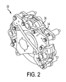
- Fig. 2 is perspective view of an example of a brake for a wind turbine.
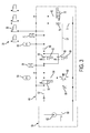
- Fig. 3 is a diagram of one embodiment of a brake block a hydraulic system for controlling the brake of a wind turbine.
- Fig. 1 shows one embodiment of a wind turbine 10.
- the wind turbine generally comprises a tower 12, a nacelle 14 supported by the tower 12, and a rotor 16 attached to the nacelle 14.
- the rotor 16 includes a hub 18 rotatably mounted to the nacelle 14 and a set of blades 20 coupled to the hub 18.
- the blades 20 convert the kinetic energy of the wind into mechanical energy used to rotate the shaft of a generator 22, as is conventional.
- the wind turbine 10 further includes a brake 30 and a hydraulic station 32 containing the components of a hydraulic system that controls the brake 30.
- the brake 30 typically includes a disc 34 configured to be coupled to a shaft and one or more calipers 36 configured to apply friction to the disc 34.
- the shaft may be a low speed shaft connected to the rotor 16, a high speed shaft connected to the generator 22, or another shaft in the drive train of the wind turbine 10 that transmits the mechanical energy generated by the rotor 16.
- the disclosure below focuses on a hydraulic system and how it may be used to control the brake 30, rather than the position of the brake 30 within the wind turbine 10 or the arrangement of the disk 34 and calipers 36.
- Figs. 1 and 2 are merely examples and that the hydraulic system described below may be used to control a brake having a different configuration or arrangement in relation to the other components of a wind turbine.
- the hydraulic system 40 includes a pump system 50 (also referred to as a "hydraulic station") that moves working fluid through the hydraulic system 40, and a brake system 44 (also referred to as a "brake block”) that controls the flow of the working fluid to the brake 30.
- the pump system 50 and brake block 44 represent different aspects of the hydraulic system 40.
- the brake block 44 may be used with any pump system for building and maintaining pressure of the working fluid, which is typically oil. Accordingly, only a generic pump system is illustrated.
- the brake block 44 includes a supply line 52 that receives the working fluid from the pump system 50 and transports it to the calipers 36.
- a first accumulator 54 and first pressure switch 56 are fluidly connected to the supply line 52, and a first activation valve 58 is located in the supply line 52 downstream of these devices. The first activation valve 58 controls the flow of the working fluid to the calipers 36.
- the hydraulic system 40 may further include a second activation valve 60 arranged in parallel with the first activation valve 58.
- a second activation valve 60 By connecting the first and second activation valves 58, 60 to respective first and second uninterrupted power supplies 62, 64 and activating them at the same time, such an arrangement has the advantage of being "failure safe”. That is, if either of the first and second activation valves 58, 60 or their associated power supply unexpectedly fails, flow through the supply line 52 can still be controlled by the other activation valve.
- Any suitable valve for controlling flow through the supply line 52 consistent with the operation of the hydraulic system 40 may be used as the first and second activation valves 58, 60.
- the first and second activation valves 58, 60 are electrically-actuated, 2-way valves.
- a second accumulator 66 may be fluidly connected to the supply line 52 downstream of the first and second activation valves 58, 60.
- Other hydraulic devices such as a flow restrictor 68 and second pressure switch 70, may be located in this portion of the supply line 52 as well.
- the supply line 52 eventually splits into several branches at the brake 30 so that the working fluid can be distributed to the various calipers 36.
- the hydraulic system 40 further includes a drainage line 74 that transports the working fluid from the calipers back to the pump system 50.
- the drainage line 74 includes several branches at the brake 30, but these branches collect the working fluid from the various calipers 36 rather than distribute it.
- a first drainage valve 76 is located in the drainage line 74 to help control pressures at the brake 30, as will be described below.
- the drainage line 74 may also transport working fluid from a relief line 84 back to the pump system 50.
- the relief line 84 is fluidly connected to the drainage line 74 downstream of the first and second drainage valves 76, 78, and to the supply line 52 upstream of the first and second activation valves 58, 60.
- Various hydraulic devices may be arranged within the relief line 84 to help control pressures within the hydraulic system 40.
- Fig. 4 illustrates an adjustable flow restrictor 86 arranged in parallel with a normally-closed, pressure relief valve 88.
- the pump system 50 shown in Fig. 4 is generic because, again, the brake block 44 of the hydraulic system 40 may be used with different pump system arrangements.
- the pump system 50 may include, for example, a tank or reservoir 90 for storing and collecting the working fluid and at least one pump 92 fluidly connected to the reservoir 90.
- the drainage line 74 returns the working fluid to the at least one pump 92 via the reservoir 90.
- the pump system 50 has been activated to pressurize the portion of the supply line 52 upstream of the first and second activation valves 58, 60.
- the pressurized working fluid does not reach the brake 30 because the first and second activation valves 58, 60 are normally closed.
- the hydraulic devices in the relief line 84 e.g., the flow restrictor 86 and pressure relief valve 88
- the pressure relief valve 88 is set to a certain level and the flow restrictor 86 is controlled so that the fluid in the supply line 52 pressurizes the first accumulator 54 to the desired level.
- the pump system 50 is deactivated, the first and second activation valves 58, 60 are opened, and the first drainage valve 76 is closed. This allows the working fluid in the supply line 52 to travel past the first and second activation valves 58, 60 and to the calipers 36.
- providing the first and second activation valves 58, 60 has the advantage of being a "failure-safe" arrangement. The working fluid can flow to the calipers 36 even if one of the first or second activation valves 58, 60 or their associated power supplies 62, 64 fails.
- the pressure stored in the first accumulator 54 is released to control the flow of the working fluid to the calipers 36.
- the flow restrictor 68 downstream of the first and second activation valves 58, 60 prevents this release from causing an abrupt surge in pressure at the brake 30. Instead, the pressure at the brake 30 is increased in a more controlled manner to provide a smoother braking action (i.e., application of force) by the calipers 36 to the disc 34. This also helps reduce the loads on the wind turbine 10 created by the braking action.
- the hydraulic system may further include an isolation valve 96 located in the supply line 52 between the pump system 50 and the first accumulator 54.
- the isolation valve 96 may be open during normal operation of the wind turbine 10, but switched to a closed position when activating the brake 30. This helps isolate the portion of the supply line 52 downstream of the isolation valve 96 so that the flow of the working fluid is only influenced by the release of pressure from the first accumulator 54.
- the first accumulator 54 controls the flow of the working fluid to the brake 30 with minimal or no interference from the pump system 50.
- the first pressure switch 56 can then be used to more accurately estimate the pressure in the first accumulator 54, as will be described below.
- the first drainage valve 76 is a check valve fluidly connected to the supply line 52 by a detection line 98.
- the detection line 98 is fluidly connected to the supply line 52 downstream of the first and second activation valves 58, 60. Any significant build-up of pressure in this portion of the supply line 52 is communicated to the first drainage valve 76 and causes it to close.
- the first drainage valve 76 closes when the first and second activation valves 58, 60 open and allow the pressure stored in the first accumulator 54 to be released into the supply line 52.
- the flow of working fluid past the first and second activation valves 58, 60 not only increases pressure at the brake 30, but also pressurizes the second accumulator 66. Eventually the working fluid at the calipers 36 reaches a pressure that corresponds to a maximum desired braking force applied to the disc 34. At this point, the first and second activation valves 58, 60 may be closed. For example, the first and second activation valves 58, 60 may be set to automatically close after a certain time period. The build up of pressure at the calipers 36 and in the second accumulator 66 may then be used to hold the brake 30 (i.e., keep the calipers 36 applied to the disc 34 with a sufficient braking force) after the drivetrain and rotor 16 are brought to a stop.
- the pump system 50 is activated (e.g., the pump 92 is turned back on) and the isolation valve 96 is opened.
- the pump system 50 supplies working fluid to the supply line 52 and first accumulator 54, which is then re-pressurized. Additionally, the working fluid downstream of the first and second activation valves 58, 60 (which remain closed after holding the brake 30) is flushed from the calipers 36.
- the first and second drainage valves 76, 78 are moved into open positions.
- the second drainage valve 78 may have a greater flow capacity than the first drainage valve 76 to drain the working fluid faster from the calipers 36, second accumulator 66, and portion of the supply line 52 downstream of the first and second activation valves 58, 60.
- the second drainage valve 78 may only need to be opened for a few seconds to help drain the working fluid.
- the hydraulic system 40 is ready to activate the brake 30 again according to the procedures described above.
- the first and second activation valves 58, 60 are in their normal, closed positions; no voltage is activating the first and second activation valves 58, 60. Accordingly, unlike conventional systems, the hydraulic system 40 does not rely upon power supplies (e.g., the first and second power supplies 62, 64) to prevent activation of the brake 30 during operation, or to maintain sufficient pressure on the brake 30 after it has been used to stop the rotor 16 from rotating. Because these time periods are significantly longer than the time required to activate the brake 30, the overall reliability of the hydraulic system 40 is increased. Although the first and second power supplies 62, 64 are still relied upon for activation of the brake 30, the failure-safe arrangement described above adds further reliability to the system.
- power supplies e.g., the first and second power supplies 62, 64
- the above-described arrangement also has the advantage of preventing damage to the brake 30 during operation even if there is a leakage or failure in one or both of the first and second activation valves 58, 60.
- the drainage line 74 and open position of the first drainage valve 76 allows the working fluid to drain from the brake 30. There is no build-up of pressure that may otherwise cause the calipers 36 to contact the disc 34 and heat up as a result of friction.
- the increase in pressure is communicated to the first drainage valve 76 via the detection line 98.
- the first drainage valve 76 then closes when the pressure increase reaches a certain level so that the pressure of the working fluid at the calipers 36 then increases according to a normal activation of the brake 30.
- the second pressure switch 70 may also be used to provide feedback about pressures in the portion of the supply line 52 downstream of the first and second activation valves 58, 60. That way, even if there is not a complete failure in the first or second activation valves 58, 60, the hydraulic system 40 can send a signal to open the valves when the pressure is high enough to close the first drainage valve 76. This further ensures that that brake 30 is applied according to normal activation profiles. Moreover, it also allows activation of the brake 30 when the leakage is large enough to warrant concerns, even if the first activation valve 58 or second activation valve 60 has not completely failed.
- Another advantage of the hydraulic system 40 is the ability to test several of the components during stopped conditions (i.e., when the brake 30 is being held after activation or when the rotor 16 is idling such that increases of pressure at the calipers 36 and application of the brake 30 does not matter).
- the first and second activation valves 58, 60 and the first and second drainage valves 76, 78 are closed.
- the first activation valve 58 is then opened while keeping the second activation valve 60 closed. If the second pressure switch 70 indicates an increase in pressure when the first drainage valve 76 is opened, the opening of the first activation valve 58 has been verified.
- the first activation valve 58 and the first drainage valve 76 may then be closed.
- the same procedure may be repeated for testing the second activation valve 60.
- the second activation valve 60 is opened while keeping the first activation valve 58 closed, and then the first drainage valve 76 is opened and the pressure is monitored with the first pressure switch 56. If the first pressure switch 56 indicates a pressure drop in the supply line 52 when the first drainage valve 76 is opened, the opening of the second activation valve 60 has been verified.
- the ability to test the first and second activation valves 58, 60 during a stopped condition enables power failures or other defects that prevent the valves from opening to be easily identified. As a result, the defects can be repaired (e.g., by replacing the first or second activation valve 58, 60 and/or the first and second power supplies 62, 64) before it affects the operation of the hydraulic system 40. If, during the testing procedures, both the first and second activation valves 58, 60 fail verification, it might be a result of the first drainage valve 76 not operating properly rather than the first and second activation valves 58, 60 failing to open. Thus, the procedure described above also serves to test the operation of the first drainage valve 76 as well.
- the first accumulator 54 may also be tested, but this test occurs after releasing the brake 30. More specifically, after opening the first and second drainage valves 76, 78 to flush working fluid from the calipers 36 (and the second accumulator 66 and portion of the supply line 52 downstream of the first and second activation valves 58, 60), the first and/or second activation valves 58, 60 may be opened. This occurs prior to activating the pump system 50 and opening the isolation valve 96 (see discussion above about releasing the brake), and allows any remaining pressure in the first accumulator 54 to be released. The first pressure switch 56 monitors the decrease in pressure in the supply line 52 until it reaches zero or some minimum valve as the working fluid is drained.
- the embodiments described above are merely examples of the invention defined by the claims that appear below.
- the first drainage valve 76 may be electrically-actuated and controlled using feedback from the second pressure switch 70. Accordingly, departures may be made from the details of this disclosure without departing from the scope or spirit of the general inventive concept.
Landscapes
- Engineering & Computer Science (AREA)
- General Engineering & Computer Science (AREA)
- Mechanical Engineering (AREA)
- Life Sciences & Earth Sciences (AREA)
- Sustainable Development (AREA)
- Sustainable Energy (AREA)
- Chemical & Material Sciences (AREA)
- Combustion & Propulsion (AREA)
- Power Engineering (AREA)
- Wind Motors (AREA)
- Braking Arrangements (AREA)
Abstract
Description
- The present invention relates to a hydraulic system for a wind turbine. More specifically, the present invention relates to a hydraulic system for operating the brake of a wind turbine and a method of controlling the brake of a wind turbine with such a hydraulic system.
- A wind turbine (also referred to as a "wind turbine generator" or WTG) is typically equipped with a mechanical brake on its drive train for bringing the rotor of the wind turbine to a standstill and maintaining the wind turbine in a "parked" (i.e., stopped) position. This may be necessary during repair and maintenance operations, for example. Even though many wind turbines include pitching mechanisms that can be controlled to bring their rotors to a standstill (referred to as "idling"), a mechanical brake may still be required for safety reasons such as emergency stops.
- Two types of mechanical brakes commonly used are disc brakes and clutch brakes. Disc brakes include a disc coupled to a shaft in the drivetrain and one or more hydraulically actuated calipers configured to apply friction to the disc via brake pads. The friction creates a braking torque that opposes the motion of the disc, thereby slowing the drivetrain and rotor. Clutch brakes include brake pads that are pre-tensioned by springs into a braking position, but compressed air or hydraulic fluid is typically used to act against the springs and release the brake pads.
- One of the challenges in designing the hydraulic system for controlling a mechanical brake is to enable quick activation for safety reasons. For example, conventional hydraulic systems for controlling a disc brake typically include supply lines leading to the brake and one or more electrically-actuated valves located in those lines. The lines are maintained with pressurized fluid during normal operation so that the brake is quickly activated when the valves are actuated. Although such a system may provide quick activation of the brake when needed, there is also a risk that the brake may be unintentionally activated when not needed. For example, one of the valves in the supply line leading to the brake may leak. Even a small leak in one of the valves may, over time, cause a pressure buildup to activate the brake.
- Additionally, valves in the supply line controlling activation of the brake are typically normally-open valves (i.e., the valves pre-tensioned into an open position). During operation the valves are electrically set into a closed position to prevent the pressurized fluid from increasing pressures at the brake. Power is switched to "off" to open the valves and activate the brake. Because the brake is only activated occasionally, the valves are highly dependent on power being "on". This arrangement has the potential to create reliability issues.
- Therefore, a hydraulic system for controlling the mechanical brake that sufficiently addresses safety concerns and minimizes the risk of unintended activation is highly desirable.
- A hydraulic system for operating a brake in a wind turbine is disclosed. The hydraulic system is based on a braking method where the brake is prevented from being activated during operation of the wind turbine by reducing or eliminating the possibility of pressure-build ups. In particular, pressurized working fluid in the hydraulic system is blocked from being supplied to the brake, and working fluid that does leak to the brake is drained. The brake is then activated by supplying the pressurized working fluid to the brake and preventing it from being drained, thereby resulting in a pressure build-up.
- In one embodiment, the brake includes a disc and at least one caliper configured to apply friction to the disc. The hydraulic system includes a pump system, a supply line fluidly connecting the pump system to the at least one caliper, a first accumulator fluidly connected to the supply line, a first activation valve located in the supply line downstream of the first accumulator, a drainage line fluidly connecting the at least one caliper to the pump system, and a first drainage valve located in the drainage line. As used herein, the terms "downstream" and "upstream" are generally used to refer to locations of components relative to each other with reference to the direction of fluid flow through the hydraulic system.
- The first activation valve may be normally closed and the first drainage valve may be normally open. Consistent with the braking method mentioned above, such an arrangement prevents a pressure build-up at the calipers and unintentional activation of the brake during operation of the wind turbine. In other words, the wind turbine may be operated with less concern of the brake being activated due to leakages and other unexpected failures. When it is desired to activate the brake, it can be accomplished by opening the first activation valve, releasing pressurized working fluid stored in the first accumulator into the supply line, and closing the first drainage valve. This creates a pressure build-up at the calipers so that they move into contact with the disc.
- After activation, the first activation valve may be closed and the wind turbine held in a stopped (i.e., "parked") condition with the brake. This may be accomplished, for example, by pressure from a second accumulator fluidly connected to the supply line downstream of the first activation valve. Holding the wind turbine in a stopped condition without needing the first activation valve to remain open also enables the first activation valve to be tested. In one testing method, the first activation is moved back into an open position while the hydraulic system holds the wind turbine in a stopped condition. The first drainage valve is opened as well, and the pressure in the supply line is monitored. The first activation valve is verified to being operating if this results in a pressure drop.
- Eventually the brake may be released by closing the first activation valve (if not already closed), opening the first drainage valve, and activating the pump system to re-pressurize the first accumulator.
- In yet another embodiment, a second activation valve is arranged in parallel with the first activation valve. The first and second activation valves have respective first and second power supplies, but may be activated/controlled at the same time. This has the advantage of being a "failure-safe" arrangement in that fluid can flow to the calipers even if one of the activation valves or their power supply fails. The first activation valve itself, the combination of the first and second activation valves, and other devices/arrangements that control activation of the brake, may generally be referred to as "activation means."
- These and other embodiments will become more apparent based on the description below.
-
Fig. 1 is a perspective view of an example of a wind turbine, with portions cut-away so that internal components of the wind turbine can be seen. -
Fig. 2 is perspective view of an example of a brake for a wind turbine. -
Fig. 3 is a diagram of one embodiment of a brake block a hydraulic system for controlling the brake of a wind turbine. -
Fig. 1 shows one embodiment of awind turbine 10. The wind turbine generally comprises atower 12, anacelle 14 supported by thetower 12, and arotor 16 attached to thenacelle 14. Therotor 16 includes ahub 18 rotatably mounted to thenacelle 14 and a set ofblades 20 coupled to thehub 18. Theblades 20 convert the kinetic energy of the wind into mechanical energy used to rotate the shaft of agenerator 22, as is conventional. - The
wind turbine 10 further includes abrake 30 and ahydraulic station 32 containing the components of a hydraulic system that controls thebrake 30. As shown inFig. 2 , thebrake 30 typically includes adisc 34 configured to be coupled to a shaft and one ormore calipers 36 configured to apply friction to thedisc 34. The shaft may be a low speed shaft connected to therotor 16, a high speed shaft connected to thegenerator 22, or another shaft in the drive train of thewind turbine 10 that transmits the mechanical energy generated by therotor 16. Indeed, the disclosure below focuses on a hydraulic system and how it may be used to control thebrake 30, rather than the position of thebrake 30 within thewind turbine 10 or the arrangement of thedisk 34 andcalipers 36. Thus, it will be appreciated thatFigs. 1 and2 are merely examples and that the hydraulic system described below may be used to control a brake having a different configuration or arrangement in relation to the other components of a wind turbine. - Now, with reference to
Fig. 3 , one embodiment of a hydraulic system 40 is shown. The hydraulic system 40 includes a pump system 50 (also referred to as a "hydraulic station") that moves working fluid through the hydraulic system 40, and a brake system 44 (also referred to as a "brake block") that controls the flow of the working fluid to thebrake 30. Thepump system 50 andbrake block 44 represent different aspects of the hydraulic system 40. In fact, thebrake block 44 may be used with any pump system for building and maintaining pressure of the working fluid, which is typically oil. Accordingly, only a generic pump system is illustrated. - The
brake block 44 includes a supply line 52 that receives the working fluid from thepump system 50 and transports it to thecalipers 36. Afirst accumulator 54 andfirst pressure switch 56 are fluidly connected to the supply line 52, and afirst activation valve 58 is located in the supply line 52 downstream of these devices. Thefirst activation valve 58 controls the flow of the working fluid to thecalipers 36. - Advantageously, however, the hydraulic system 40 may further include a
second activation valve 60 arranged in parallel with thefirst activation valve 58. By connecting the first andsecond activation valves second activation valves second activation valves second activation valves - A
second accumulator 66 may be fluidly connected to the supply line 52 downstream of the first andsecond activation valves flow restrictor 68 andsecond pressure switch 70, may be located in this portion of the supply line 52 as well. The supply line 52 eventually splits into several branches at thebrake 30 so that the working fluid can be distributed to thevarious calipers 36. - The hydraulic system 40 further includes a drainage line 74 that transports the working fluid from the calipers back to the
pump system 50. Like the supply line 52, the drainage line 74 includes several branches at thebrake 30, but these branches collect the working fluid from thevarious calipers 36 rather than distribute it. Afirst drainage valve 76 is located in the drainage line 74 to help control pressures at thebrake 30, as will be described below. There may also be asecond drainage valve 78 arranged in parallel with thefirst drainage valve 76 via abypass line 80. To this end, thebypass line 80 is fluidly connected to the drainage line 74 both upstream and downstream of thefirst drainage valve 76. - The drainage line 74 may also transport working fluid from a
relief line 84 back to thepump system 50. Therelief line 84 is fluidly connected to the drainage line 74 downstream of the first andsecond drainage valves second activation valves relief line 84 to help control pressures within the hydraulic system 40. For example, Fig. 4 illustrates anadjustable flow restrictor 86 arranged in parallel with a normally-closed,pressure relief valve 88. - The
pump system 50 shown in Fig. 4 is generic because, again, thebrake block 44 of the hydraulic system 40 may be used with different pump system arrangements. Thepump system 50 may include, for example, a tank orreservoir 90 for storing and collecting the working fluid and at least onepump 92 fluidly connected to thereservoir 90. In such an embodiment, the drainage line 74 returns the working fluid to the at least onepump 92 via thereservoir 90. - The operation of the hydraulic system 40 for controlling the
brake 30 will now be described in further detail. Under normal operating conditions of the wind turbine 10 (i.e., when therotor 16 is moving and thebrake 30 is not applied), thepump system 50 has been activated to pressurize the portion of the supply line 52 upstream of the first andsecond activation valves brake 30 because the first andsecond activation valves flow restrictor 86 and pressure relief valve 88) prevent pressurized working fluid from freely flowing through therelief line 84, into the drainage line 74, and to thetank 90. Instead, thepressure relief valve 88 is set to a certain level and theflow restrictor 86 is controlled so that the fluid in the supply line 52 pressurizes thefirst accumulator 54 to the desired level. - To activate the
brake 30, thepump system 50 is deactivated, the first andsecond activation valves first drainage valve 76 is closed. This allows the working fluid in the supply line 52 to travel past the first andsecond activation valves calipers 36. As mentioned above, providing the first andsecond activation valves calipers 36 even if one of the first orsecond activation valves - The pressure stored in the
first accumulator 54 is released to control the flow of the working fluid to thecalipers 36. However, theflow restrictor 68 downstream of the first andsecond activation valves brake 30. Instead, the pressure at thebrake 30 is increased in a more controlled manner to provide a smoother braking action (i.e., application of force) by thecalipers 36 to thedisc 34. This also helps reduce the loads on thewind turbine 10 created by the braking action. - If desired, the hydraulic system may further include an isolation valve 96 located in the supply line 52 between the
pump system 50 and thefirst accumulator 54. The isolation valve 96 may be open during normal operation of thewind turbine 10, but switched to a closed position when activating thebrake 30. This helps isolate the portion of the supply line 52 downstream of the isolation valve 96 so that the flow of the working fluid is only influenced by the release of pressure from thefirst accumulator 54. In other words, thefirst accumulator 54 controls the flow of the working fluid to thebrake 30 with minimal or no interference from thepump system 50. Thefirst pressure switch 56 can then be used to more accurately estimate the pressure in thefirst accumulator 54, as will be described below. - The pressure of the working fluid increases at the brake 30-resulting in the application of the
calipers 36 to the disc 34-because the first andsecond drainage valves first drainage valve 76 is a check valve fluidly connected to the supply line 52 by adetection line 98. Thedetection line 98 is fluidly connected to the supply line 52 downstream of the first andsecond activation valves first drainage valve 76 and causes it to close. Thus, thefirst drainage valve 76 closes when the first andsecond activation valves first accumulator 54 to be released into the supply line 52. - The flow of working fluid past the first and
second activation valves brake 30, but also pressurizes thesecond accumulator 66. Eventually the working fluid at thecalipers 36 reaches a pressure that corresponds to a maximum desired braking force applied to thedisc 34. At this point, the first andsecond activation valves second activation valves calipers 36 and in thesecond accumulator 66 may then be used to hold the brake 30 (i.e., keep thecalipers 36 applied to thedisc 34 with a sufficient braking force) after the drivetrain androtor 16 are brought to a stop. - To release the
brake 30, thepump system 50 is activated (e.g., thepump 92 is turned back on) and the isolation valve 96 is opened. Thepump system 50 supplies working fluid to the supply line 52 andfirst accumulator 54, which is then re-pressurized. Additionally, the working fluid downstream of the first andsecond activation valves 58, 60 (which remain closed after holding the brake 30) is flushed from thecalipers 36. To this end, the first andsecond drainage valves second drainage valve 78 may have a greater flow capacity than thefirst drainage valve 76 to drain the working fluid faster from thecalipers 36,second accumulator 66, and portion of the supply line 52 downstream of the first andsecond activation valves first drainage valve 76, thesecond drainage valve 78 may only need to be opened for a few seconds to help drain the working fluid. When thesecond drainage valve 78 is moved back to its normal, closed position, the hydraulic system 40 is ready to activate thebrake 30 again according to the procedures described above. - Therefore, both during normal operation of the
wind turbine 10 and during stopped conditions (caused by activation of the brake 30), the first andsecond activation valves second activation valves brake 30 during operation, or to maintain sufficient pressure on thebrake 30 after it has been used to stop therotor 16 from rotating. Because these time periods are significantly longer than the time required to activate thebrake 30, the overall reliability of the hydraulic system 40 is increased. Although the first and second power supplies 62, 64 are still relied upon for activation of thebrake 30, the failure-safe arrangement described above adds further reliability to the system. - The above-described arrangement also has the advantage of preventing damage to the
brake 30 during operation even if there is a leakage or failure in one or both of the first andsecond activation valves second activation valve calipers 36, the drainage line 74 and open position of thefirst drainage valve 76 allows the working fluid to drain from thebrake 30. There is no build-up of pressure that may otherwise cause thecalipers 36 to contact thedisc 34 and heat up as a result of friction. On the other hand, if one or both of the first andsecond activation valves first drainage valve 76 via thedetection line 98. Thefirst drainage valve 76 then closes when the pressure increase reaches a certain level so that the pressure of the working fluid at thecalipers 36 then increases according to a normal activation of thebrake 30. - Other advantageous features will be readily apparent to those skilled in the art. For example, the
second pressure switch 70 may also be used to provide feedback about pressures in the portion of the supply line 52 downstream of the first andsecond activation valves second activation valves first drainage valve 76. This further ensures that thatbrake 30 is applied according to normal activation profiles. Moreover, it also allows activation of thebrake 30 when the leakage is large enough to warrant concerns, even if thefirst activation valve 58 orsecond activation valve 60 has not completely failed. - Another advantage of the hydraulic system 40 is the ability to test several of the components during stopped conditions (i.e., when the
brake 30 is being held after activation or when therotor 16 is idling such that increases of pressure at thecalipers 36 and application of thebrake 30 does not matter). In such conditions, the first andsecond activation valves second drainage valves first activation valve 58 is then opened while keeping thesecond activation valve 60 closed. If thesecond pressure switch 70 indicates an increase in pressure when thefirst drainage valve 76 is opened, the opening of thefirst activation valve 58 has been verified. Thefirst activation valve 58 and thefirst drainage valve 76 may then be closed. - The same procedure may be repeated for testing the
second activation valve 60. In particular, thesecond activation valve 60 is opened while keeping thefirst activation valve 58 closed, and then thefirst drainage valve 76 is opened and the pressure is monitored with thefirst pressure switch 56. If thefirst pressure switch 56 indicates a pressure drop in the supply line 52 when thefirst drainage valve 76 is opened, the opening of thesecond activation valve 60 has been verified. - The ability to test the first and
second activation valves second activation valve second activation valves first drainage valve 76 not operating properly rather than the first andsecond activation valves first drainage valve 76 as well. - Finally, the
first accumulator 54 may also be tested, but this test occurs after releasing thebrake 30. More specifically, after opening the first andsecond drainage valves second accumulator 66 and portion of the supply line 52 downstream of the first andsecond activation valves 58, 60), the first and/orsecond activation valves pump system 50 and opening the isolation valve 96 (see discussion above about releasing the brake), and allows any remaining pressure in thefirst accumulator 54 to be released. Thefirst pressure switch 56 monitors the decrease in pressure in the supply line 52 until it reaches zero or some minimum valve as the working fluid is drained. The amount of time it takes for the pressure to decrease from a predetermined level (which may be the same or less than the pressure before opening the first and/orsecond activation valves 58, 60) to zero (or another predetermined level), is compared to a predicted value for a normally-operating accumulator. If the time is within an acceptable deviation from the predicted value, thefirst accumulator 54 is operating sufficiently. - The embodiments described above are merely examples of the invention defined by the claims that appear below. Those skilled in the design of hydraulic braking systems will appreciate additional examples, modifications, and advantages based on the description. For example, rather than communicating pressures in the supply 52 to the
first drainage valve 76 via thedetection line 98, thefirst drainage valve 76 may be electrically-actuated and controlled using feedback from thesecond pressure switch 70. Accordingly, departures may be made from the details of this disclosure without departing from the scope or spirit of the general inventive concept.
Claims (19)
- A hydraulic system for operating a brake in a wind turbine, the brake including a disc and at least one caliper configured to apply friction to the disc, the hydraulic system comprising:a pump system;a supply line fluidly connecting the pump system to the at least one caliper;a first accumulator fluidly connected to the supply line;a first activation valve located in the supply line downstream of the first accumulator;a drainage line fluidly connecting the at least one caliper to the pump system; anda first drainage valve located in the drainage line.
- A hydraulic system according to claim 1, wherein the first activation valve is normally closed and the first drainage valve is normally open.
- A hydraulic system according to claims 1 or 2, wherein the pump system further comprises:a reservoir for storing working fluid; andat least one pump fluidly connected to the reservoir, the drainage line being fluidly connected to the at least one pump via the reservoir.
- A hydraulic system according to any of claims 1-3, further comprising:a detection line configured to communicate pressures from the supply line to the first drainage valve, the detection line being connected to the supply line downstream of the first activation valve.
- A hydraulic system according to any of claims 1-4, further comprising:a flow restrictor located in the supply line downstream of the first accumulator.
- A hydraulic system according to any of claims 1-5, further comprising:a second accumulator fluidly connected to the supply line downstream of the first activation valve.
- A hydraulic system according to any of claims 1-6, further comprising:at least one pressure switch located in the supply line between the first accumulator and the at least one caliper.
- A hydraulic system according to any of claims 1-7, further comprising:an isolation valve located in the supply line between the pump system and the first accumulator.
- A hydraulic system according to any of claims 1-8, further comprising:a second activation valve arranged in parallel with the first activation valve;a first power supply associated with the first activation valve; anda second power supply associated with the second activation valve.
- A hydraulic system according to any of claims 1-9, further comprising:a bypass line fluidly connected to the drainage line between the at least one caliper and the first drainage valve, the bypass line also being fluidly connected to the drainage line downstream of the first drainage valve; anda second drainage valve located in the bypass line, the second drainage valve having a greater flow capacity than the first drainage valve.
- A wind turbine, comprising:a tower;a nacelle supported by the tower;a rotor rotatably coupled to the nacelle;a shaft located in the nacelle and drivingly coupled to the rotor;a brake including a disc coupled to the shaft and at least one caliper configured to apply friction to the disc; anda hydraulic system according to any of claims 1-10 for operating the brake.
- A method of controlling a brake of a wind turbine with a hydraulic system according to any of claims 1-10, comprising:operating the wind turbine without the brake being activated, the first activation valve of the hydraulic system being closed and the first drainage valve being open to prevent a pressure build-up at the at least one caliper; andactivating the brake by:opening the first activation valve;releasing pressurized working fluid stored in the first accumulator into the supply line; andclosing the first drainage valve to create a pressure build-up at the at least one caliper.
- A method according to claim 12, further comprising:releasing the brake by:closing the first activation valve after the brake has been activated;opening the first drainage valve; andactivating the pump system to re-pressurize the first accumulator.
- A method according to claim 12, further comprising:closing the first activation valve after the brake has been activated; andholding the wind turbine in a stopped condition with the brake after closing the first activation valve.
- A method according to claim 14, further comprising:opening the first activation valve while holding the wind turbine in a stopped condition;opening the first drainage valve; andmonitoring pressure in the supply line to determine if opening the first drainage valve resulted in a pressure drop, thereby indicating that the first activation valve has been opened.
- A method of controlling a brake of a wind turbine, comprising:preventing activation of the brake during operation of the wind turbine by:blocking pressurized working fluid in the hydraulic system from being supplied to the brake; anddraining any working fluid that leaks to the brake to prevent a pressure build-up and activation; andactivating the brake by:supplying the pressurized working fluid to the brake; andpreventing the pressurized working fluid from being drained from the brake, thereby resulting in a pressure build-up.
- A method according to claim 16, wherein blocking pressurized working fluid from being supplied to the brake comprises:arranging first and second activation valves in parallel in a supply line configured to communicate the working fluid to the brake, the first and second activation valves being normally closed and having respective first and second power supplies.
- A method according to claim 17, wherein the brake is activated until the wind turbine stops operating, the method further comprising:closing the first and second activation valves; andholding the wind turbine in a stopped condition with an accumulator located in the supply line downstream of the first and second activation valves.
- A method according to claim 18, further comprising:testing the function of the first and second activation valves when holding the wind turbine in a stopped condition by:a) opening the first activation valve;b) opening a drainage valve in a drainage line that drains working fluid from the brake; andc) monitoring pressure in the supply line to determine if opening the drainage valve resulted in a pressure increase downstream of the first and second activation valves, thereby indicating that the first activation valve has been opened;d) closing the drainage valve; ande) repeating steps a-d for the second activation valve.
Applications Claiming Priority (1)
| Application Number | Priority Date | Filing Date | Title |
|---|---|---|---|
| DKPA200970031 | 2009-06-16 |
Publications (3)
| Publication Number | Publication Date |
|---|---|
| EP2267304A2 true EP2267304A2 (en) | 2010-12-29 |
| EP2267304A3 EP2267304A3 (en) | 2018-04-25 |
| EP2267304B1 EP2267304B1 (en) | 2021-08-18 |
Family
ID=42613887
Family Applications (1)
| Application Number | Title | Priority Date | Filing Date |
|---|---|---|---|
| EP10165885.4A Active EP2267304B1 (en) | 2009-06-16 | 2010-06-14 | Hydraulic system and method for operating a brake of a wind turbine |
Country Status (4)
| Country | Link |
|---|---|
| US (1) | US8123304B2 (en) |
| EP (1) | EP2267304B1 (en) |
| CN (1) | CN101922411B (en) |
| ES (1) | ES2884098T3 (en) |
Cited By (2)
| Publication number | Priority date | Publication date | Assignee | Title |
|---|---|---|---|---|
| EP2472104A1 (en) * | 2011-01-04 | 2012-07-04 | General Electric Company | Method and system for braking in a wind turbine |
| EP2778396A1 (en) * | 2013-03-13 | 2014-09-17 | Areva Wind GmbH | Hydraulic braking system, wind generator comprising a hydraulic braking system and use of an automatic air bleed valve in a hydraulic braking system |
Families Citing this family (9)
| Publication number | Priority date | Publication date | Assignee | Title |
|---|---|---|---|---|
| US8269367B2 (en) * | 2010-01-13 | 2012-09-18 | Hiwin Mikrosystem Corp. | Shaft brake mechanism of wind power generator |
| US8872375B2 (en) * | 2010-03-05 | 2014-10-28 | Deka Products Limited Partnership | Wind turbine apparatus, systems and methods |
| US9476467B2 (en) * | 2012-07-24 | 2016-10-25 | Haisheng Qiang | Dual-directions braking method of disc brake, braking mechanism and braking system thereof |
| CN104583109B (en) | 2012-08-02 | 2016-09-21 | 奥的斯电梯公司 | Hydraulic braking system for elevators |
| CN105408624A (en) * | 2013-07-04 | 2016-03-16 | 奥伦达能源解决方案公司 | Overrun protection for wind turbines |
| DE102017102375B3 (en) * | 2017-02-07 | 2018-06-28 | Hoerbiger Automatisierungstechnik Holding Gmbh | Wind turbine |
| GB2588187A (en) * | 2019-10-11 | 2021-04-21 | Caterpillar Inc | Braking system |
| CN112727679B (en) * | 2020-12-29 | 2022-05-31 | 崇礼新天风能有限公司 | Speed reduction device based on friction braking mechanism and wind driven generator braking system |
| CN119686939A (en) * | 2023-09-22 | 2025-03-25 | 哈威液压股份公司 | Hydraulic system for a rotor brake, rotor brake and wind turbine |
Family Cites Families (18)
| Publication number | Priority date | Publication date | Assignee | Title |
|---|---|---|---|---|
| GB688170A (en) | 1950-04-08 | 1953-02-25 | United Aircraft Corp | Improvements in or relating to variable pitch propellers |
| GB696657A (en) | 1950-05-25 | 1953-09-02 | United Aircraft Corp | Improvements in or relating to propeller pitch changing devices |
| GB868419A (en) | 1956-12-18 | 1961-05-17 | United Aircraft Corp | Hydraulic system for adjustable pitch aeronautical propeller |
| DE3204695A1 (en) | 1982-02-11 | 1983-08-18 | Siemens AG, 1000 Berlin und 8000 München | Device for the safety braking of hoists, in particular drum-type hoists |
| ES2129480T3 (en) * | 1993-10-18 | 1999-06-16 | Inventio Ag | BRAKING SAFETY DEVICE FOR ELEVATOR CABINS. |
| GB2303676B (en) * | 1995-07-22 | 1999-03-10 | Twiflex Ltd | Fluid control circuit and brake system |
| WO1998023474A1 (en) | 1996-11-22 | 1998-06-04 | Svendborg Brakes A/S | A hydraulic braking system |
| JP4380897B2 (en) * | 2000-08-04 | 2009-12-09 | 三菱重工業株式会社 | Brake shock absorber for windmill |
| ES2345880T3 (en) * | 2002-03-23 | 2010-10-05 | General Electric Company | HYDRAULIC BRAKE SYSTEM FOR A WIND ENERGY INSTALLATION. |
| WO2003080414A1 (en) | 2002-03-23 | 2003-10-02 | General Electric Company | Hydraulic brake system for a wind energy plant |
| EP1636489A1 (en) * | 2003-06-11 | 2006-03-22 | General Electric Company | Remote shut down of offshore wind turbine |
| US20050110337A1 (en) * | 2003-11-25 | 2005-05-26 | Yuhong Zheng | Electronic pressure relief strategy |
| JP4643965B2 (en) * | 2004-09-30 | 2011-03-02 | 大和ハウス工業株式会社 | Hydraulic brake device for windmill and braking method for windmill |
| DE102004057522A1 (en) * | 2004-10-08 | 2006-04-13 | Bosch Rexroth Aktiengesellschaft | Braking device for wind power plant has 3/2-path seat valve, via which pressure cavity can be connected to pressure fluid source and tank vent to operate brakes |
| DE102007002137A1 (en) * | 2007-01-10 | 2008-07-17 | Nordex Energy Gmbh | Wind energy plant with a hydraulically actuated rotor brake |
| DE102007002136B4 (en) * | 2007-01-10 | 2010-02-18 | Nordex Energy Gmbh | Wind energy plant with a hydraulically actuated rotor brake and method for hydraulic control of a rotor brake |
| CN101033733A (en) * | 2007-04-11 | 2007-09-12 | 浙江大学 | Digital intelligent hydraulic brake system for large and medium-sized wind turbines |
| CN201246284Y (en) * | 2008-08-29 | 2009-05-27 | 江苏苏亚机电制造有限公司 | Flexible brake system of wind generating set |
-
2010
- 2010-06-13 CN CN201010246901.0A patent/CN101922411B/en active Active
- 2010-06-14 ES ES10165885T patent/ES2884098T3/en active Active
- 2010-06-14 EP EP10165885.4A patent/EP2267304B1/en active Active
- 2010-06-16 US US12/816,874 patent/US8123304B2/en active Active
Non-Patent Citations (1)
| Title |
|---|
| None |
Cited By (2)
| Publication number | Priority date | Publication date | Assignee | Title |
|---|---|---|---|---|
| EP2472104A1 (en) * | 2011-01-04 | 2012-07-04 | General Electric Company | Method and system for braking in a wind turbine |
| EP2778396A1 (en) * | 2013-03-13 | 2014-09-17 | Areva Wind GmbH | Hydraulic braking system, wind generator comprising a hydraulic braking system and use of an automatic air bleed valve in a hydraulic braking system |
Also Published As
| Publication number | Publication date |
|---|---|
| CN101922411B (en) | 2014-10-29 |
| US20110014048A1 (en) | 2011-01-20 |
| US8123304B2 (en) | 2012-02-28 |
| EP2267304A3 (en) | 2018-04-25 |
| CN101922411A (en) | 2010-12-22 |
| EP2267304B1 (en) | 2021-08-18 |
| ES2884098T3 (en) | 2021-12-10 |
Similar Documents
| Publication | Publication Date | Title |
|---|---|---|
| US8123304B2 (en) | Hydraulic system and method for operating a brake of a wind turbine | |
| KR101158618B1 (en) | Wind turbine generator and soundness diagnosis method thereof | |
| CA3152474C (en) | Electronically controllable and testable turbine trip system and method with redundant bleed manifolds | |
| US6265785B1 (en) | Non-volatile over speed control system for wind turbines | |
| US7494193B2 (en) | Wind energy plant with a hydraulically actuated rotor brake | |
| CN100436216C (en) | Hydraulic braking systems in wind power plants | |
| US7874241B2 (en) | Electronically controllable and testable turbine trip system | |
| US7997074B2 (en) | Hydraulic station and method for controlling pressure in a hydraulic system of a wind turbine | |
| CN103201508B (en) | Brake unit for the hydraulic pressure of wind energy plant | |
| EP3542053A1 (en) | Wind turbine with brake device and method for operating same | |
| WO2003080414A1 (en) | Hydraulic brake system for a wind energy plant | |
| JP2002303255A (en) | Wind power generator | |
| US9796573B2 (en) | Lifting-device brake system | |
| EP2778396B1 (en) | Hydraulic braking system, wind generator comprising a hydraulic braking system and use of an automatic air bleed valve in a hydraulic braking system |
Legal Events
| Date | Code | Title | Description |
|---|---|---|---|
| PUAI | Public reference made under article 153(3) epc to a published international application that has entered the european phase |
Free format text: ORIGINAL CODE: 0009012 |
|
| AK | Designated contracting states |
Kind code of ref document: A2 Designated state(s): AL AT BE BG CH CY CZ DE DK EE ES FI FR GB GR HR HU IE IS IT LI LT LU LV MC MK MT NL NO PL PT RO SE SI SK SM TR |
|
| AX | Request for extension of the european patent |
Extension state: BA ME RS |
|
| RAP1 | Party data changed (applicant data changed or rights of an application transferred) |
Owner name: VESTAS WIND SYSTEMS A/S |
|
| RAP1 | Party data changed (applicant data changed or rights of an application transferred) |
Owner name: VESTAS WIND SYSTEMS A/S |
|
| PUAL | Search report despatched |
Free format text: ORIGINAL CODE: 0009013 |
|
| AK | Designated contracting states |
Kind code of ref document: A3 Designated state(s): AL AT BE BG CH CY CZ DE DK EE ES FI FR GB GR HR HU IE IS IT LI LT LU LV MC MK MT NL NO PL PT RO SE SI SK SM TR |
|
| AX | Request for extension of the european patent |
Extension state: BA ME RS |
|
| RIC1 | Information provided on ipc code assigned before grant |
Ipc: F03D 7/02 20060101AFI20180319BHEP Ipc: F03D 11/00 20060101ALI20180319BHEP |
|
| STAA | Information on the status of an ep patent application or granted ep patent |
Free format text: STATUS: REQUEST FOR EXAMINATION WAS MADE |
|
| 17P | Request for examination filed |
Effective date: 20181008 |
|
| RBV | Designated contracting states (corrected) |
Designated state(s): AL AT BE BG CH CY CZ DE DK EE ES FI FR GB GR HR HU IE IS IT LI LT LU LV MC MK MT NL NO PL PT RO SE SI SK SM TR |
|
| RIC1 | Information provided on ipc code assigned before grant |
Ipc: F03D 11/00 20060101ALI20180319BHEP Ipc: F03D 7/02 20060101AFI20180319BHEP |
|
| STAA | Information on the status of an ep patent application or granted ep patent |
Free format text: STATUS: EXAMINATION IS IN PROGRESS |
|
| 17Q | First examination report despatched |
Effective date: 20200720 |
|
| GRAP | Despatch of communication of intention to grant a patent |
Free format text: ORIGINAL CODE: EPIDOSNIGR1 |
|
| STAA | Information on the status of an ep patent application or granted ep patent |
Free format text: STATUS: GRANT OF PATENT IS INTENDED |
|
| RIC1 | Information provided on ipc code assigned before grant |
Ipc: F03D 7/02 20060101AFI20210303BHEP |
|
| INTG | Intention to grant announced |
Effective date: 20210316 |
|
| GRAS | Grant fee paid |
Free format text: ORIGINAL CODE: EPIDOSNIGR3 |
|
| GRAA | (expected) grant |
Free format text: ORIGINAL CODE: 0009210 |
|
| STAA | Information on the status of an ep patent application or granted ep patent |
Free format text: STATUS: THE PATENT HAS BEEN GRANTED |
|
| AK | Designated contracting states |
Kind code of ref document: B1 Designated state(s): AL AT BE BG CH CY CZ DE DK EE ES FI FR GB GR HR HU IE IS IT LI LT LU LV MC MK MT NL NO PL PT RO SE SI SK SM TR |
|
| REG | Reference to a national code |
Ref country code: GB Ref legal event code: FG4D |
|
| REG | Reference to a national code |
Ref country code: CH Ref legal event code: EP |
|
| REG | Reference to a national code |
Ref country code: DE Ref legal event code: R096 Ref document number: 602010067449 Country of ref document: DE |
|
| REG | Reference to a national code |
Ref country code: IE Ref legal event code: FG4D Ref country code: AT Ref legal event code: REF Ref document number: 1421869 Country of ref document: AT Kind code of ref document: T Effective date: 20210915 |
|
| REG | Reference to a national code |
Ref country code: LT Ref legal event code: MG9D Ref country code: ES Ref legal event code: FG2A Ref document number: 2884098 Country of ref document: ES Kind code of ref document: T3 Effective date: 20211210 |
|
| REG | Reference to a national code |
Ref country code: NL Ref legal event code: MP Effective date: 20210818 |
|
| REG | Reference to a national code |
Ref country code: AT Ref legal event code: MK05 Ref document number: 1421869 Country of ref document: AT Kind code of ref document: T Effective date: 20210818 |
|
| PG25 | Lapsed in a contracting state [announced via postgrant information from national office to epo] |
Ref country code: HR Free format text: LAPSE BECAUSE OF FAILURE TO SUBMIT A TRANSLATION OF THE DESCRIPTION OR TO PAY THE FEE WITHIN THE PRESCRIBED TIME-LIMIT Effective date: 20210818 Ref country code: SE Free format text: LAPSE BECAUSE OF FAILURE TO SUBMIT A TRANSLATION OF THE DESCRIPTION OR TO PAY THE FEE WITHIN THE PRESCRIBED TIME-LIMIT Effective date: 20210818 Ref country code: LT Free format text: LAPSE BECAUSE OF FAILURE TO SUBMIT A TRANSLATION OF THE DESCRIPTION OR TO PAY THE FEE WITHIN THE PRESCRIBED TIME-LIMIT Effective date: 20210818 Ref country code: AT Free format text: LAPSE BECAUSE OF FAILURE TO SUBMIT A TRANSLATION OF THE DESCRIPTION OR TO PAY THE FEE WITHIN THE PRESCRIBED TIME-LIMIT Effective date: 20210818 Ref country code: BG Free format text: LAPSE BECAUSE OF FAILURE TO SUBMIT A TRANSLATION OF THE DESCRIPTION OR TO PAY THE FEE WITHIN THE PRESCRIBED TIME-LIMIT Effective date: 20211118 Ref country code: PT Free format text: LAPSE BECAUSE OF FAILURE TO SUBMIT A TRANSLATION OF THE DESCRIPTION OR TO PAY THE FEE WITHIN THE PRESCRIBED TIME-LIMIT Effective date: 20211220 Ref country code: NO Free format text: LAPSE BECAUSE OF FAILURE TO SUBMIT A TRANSLATION OF THE DESCRIPTION OR TO PAY THE FEE WITHIN THE PRESCRIBED TIME-LIMIT Effective date: 20211118 Ref country code: FI Free format text: LAPSE BECAUSE OF FAILURE TO SUBMIT A TRANSLATION OF THE DESCRIPTION OR TO PAY THE FEE WITHIN THE PRESCRIBED TIME-LIMIT Effective date: 20210818 |
|
| PG25 | Lapsed in a contracting state [announced via postgrant information from national office to epo] |
Ref country code: PL Free format text: LAPSE BECAUSE OF FAILURE TO SUBMIT A TRANSLATION OF THE DESCRIPTION OR TO PAY THE FEE WITHIN THE PRESCRIBED TIME-LIMIT Effective date: 20210818 Ref country code: LV Free format text: LAPSE BECAUSE OF FAILURE TO SUBMIT A TRANSLATION OF THE DESCRIPTION OR TO PAY THE FEE WITHIN THE PRESCRIBED TIME-LIMIT Effective date: 20210818 Ref country code: GR Free format text: LAPSE BECAUSE OF FAILURE TO SUBMIT A TRANSLATION OF THE DESCRIPTION OR TO PAY THE FEE WITHIN THE PRESCRIBED TIME-LIMIT Effective date: 20211119 |
|
| PG25 | Lapsed in a contracting state [announced via postgrant information from national office to epo] |
Ref country code: NL Free format text: LAPSE BECAUSE OF FAILURE TO SUBMIT A TRANSLATION OF THE DESCRIPTION OR TO PAY THE FEE WITHIN THE PRESCRIBED TIME-LIMIT Effective date: 20210818 |
|
| PG25 | Lapsed in a contracting state [announced via postgrant information from national office to epo] |
Ref country code: DK Free format text: LAPSE BECAUSE OF FAILURE TO SUBMIT A TRANSLATION OF THE DESCRIPTION OR TO PAY THE FEE WITHIN THE PRESCRIBED TIME-LIMIT Effective date: 20210818 |
|
| REG | Reference to a national code |
Ref country code: DE Ref legal event code: R097 Ref document number: 602010067449 Country of ref document: DE |
|
| PG25 | Lapsed in a contracting state [announced via postgrant information from national office to epo] |
Ref country code: SM Free format text: LAPSE BECAUSE OF FAILURE TO SUBMIT A TRANSLATION OF THE DESCRIPTION OR TO PAY THE FEE WITHIN THE PRESCRIBED TIME-LIMIT Effective date: 20210818 Ref country code: SK Free format text: LAPSE BECAUSE OF FAILURE TO SUBMIT A TRANSLATION OF THE DESCRIPTION OR TO PAY THE FEE WITHIN THE PRESCRIBED TIME-LIMIT Effective date: 20210818 Ref country code: RO Free format text: LAPSE BECAUSE OF FAILURE TO SUBMIT A TRANSLATION OF THE DESCRIPTION OR TO PAY THE FEE WITHIN THE PRESCRIBED TIME-LIMIT Effective date: 20210818 Ref country code: EE Free format text: LAPSE BECAUSE OF FAILURE TO SUBMIT A TRANSLATION OF THE DESCRIPTION OR TO PAY THE FEE WITHIN THE PRESCRIBED TIME-LIMIT Effective date: 20210818 Ref country code: CZ Free format text: LAPSE BECAUSE OF FAILURE TO SUBMIT A TRANSLATION OF THE DESCRIPTION OR TO PAY THE FEE WITHIN THE PRESCRIBED TIME-LIMIT Effective date: 20210818 Ref country code: AL Free format text: LAPSE BECAUSE OF FAILURE TO SUBMIT A TRANSLATION OF THE DESCRIPTION OR TO PAY THE FEE WITHIN THE PRESCRIBED TIME-LIMIT Effective date: 20210818 |
|
| PLBE | No opposition filed within time limit |
Free format text: ORIGINAL CODE: 0009261 |
|
| STAA | Information on the status of an ep patent application or granted ep patent |
Free format text: STATUS: NO OPPOSITION FILED WITHIN TIME LIMIT |
|
| 26N | No opposition filed |
Effective date: 20220519 |
|
| PG25 | Lapsed in a contracting state [announced via postgrant information from national office to epo] |
Ref country code: IT Free format text: LAPSE BECAUSE OF FAILURE TO SUBMIT A TRANSLATION OF THE DESCRIPTION OR TO PAY THE FEE WITHIN THE PRESCRIBED TIME-LIMIT Effective date: 20210818 |
|
| PG25 | Lapsed in a contracting state [announced via postgrant information from national office to epo] |
Ref country code: SI Free format text: LAPSE BECAUSE OF FAILURE TO SUBMIT A TRANSLATION OF THE DESCRIPTION OR TO PAY THE FEE WITHIN THE PRESCRIBED TIME-LIMIT Effective date: 20210818 |
|
| PG25 | Lapsed in a contracting state [announced via postgrant information from national office to epo] |
Ref country code: MC Free format text: LAPSE BECAUSE OF FAILURE TO SUBMIT A TRANSLATION OF THE DESCRIPTION OR TO PAY THE FEE WITHIN THE PRESCRIBED TIME-LIMIT Effective date: 20210818 |
|
| REG | Reference to a national code |
Ref country code: CH Ref legal event code: PL |
|
| REG | Reference to a national code |
Ref country code: BE Ref legal event code: MM Effective date: 20220630 |
|
| PG25 | Lapsed in a contracting state [announced via postgrant information from national office to epo] |
Ref country code: LU Free format text: LAPSE BECAUSE OF NON-PAYMENT OF DUE FEES Effective date: 20220614 Ref country code: LI Free format text: LAPSE BECAUSE OF NON-PAYMENT OF DUE FEES Effective date: 20220630 Ref country code: IE Free format text: LAPSE BECAUSE OF NON-PAYMENT OF DUE FEES Effective date: 20220614 Ref country code: CH Free format text: LAPSE BECAUSE OF NON-PAYMENT OF DUE FEES Effective date: 20220630 |
|
| PG25 | Lapsed in a contracting state [announced via postgrant information from national office to epo] |
Ref country code: BE Free format text: LAPSE BECAUSE OF NON-PAYMENT OF DUE FEES Effective date: 20220630 |
|
| P01 | Opt-out of the competence of the unified patent court (upc) registered |
Effective date: 20230521 |
|
| PG25 | Lapsed in a contracting state [announced via postgrant information from national office to epo] |
Ref country code: HU Free format text: LAPSE BECAUSE OF FAILURE TO SUBMIT A TRANSLATION OF THE DESCRIPTION OR TO PAY THE FEE WITHIN THE PRESCRIBED TIME-LIMIT; INVALID AB INITIO Effective date: 20100614 |
|
| PG25 | Lapsed in a contracting state [announced via postgrant information from national office to epo] |
Ref country code: MK Free format text: LAPSE BECAUSE OF FAILURE TO SUBMIT A TRANSLATION OF THE DESCRIPTION OR TO PAY THE FEE WITHIN THE PRESCRIBED TIME-LIMIT Effective date: 20210818 Ref country code: CY Free format text: LAPSE BECAUSE OF FAILURE TO SUBMIT A TRANSLATION OF THE DESCRIPTION OR TO PAY THE FEE WITHIN THE PRESCRIBED TIME-LIMIT Effective date: 20210818 |
|
| PG25 | Lapsed in a contracting state [announced via postgrant information from national office to epo] |
Ref country code: MT Free format text: LAPSE BECAUSE OF FAILURE TO SUBMIT A TRANSLATION OF THE DESCRIPTION OR TO PAY THE FEE WITHIN THE PRESCRIBED TIME-LIMIT Effective date: 20210818 |
|
| PGFP | Annual fee paid to national office [announced via postgrant information from national office to epo] |
Ref country code: DE Payment date: 20250626 Year of fee payment: 16 |
|
| PGFP | Annual fee paid to national office [announced via postgrant information from national office to epo] |
Ref country code: GB Payment date: 20250617 Year of fee payment: 16 |
|
| PGFP | Annual fee paid to national office [announced via postgrant information from national office to epo] |
Ref country code: FR Payment date: 20250624 Year of fee payment: 16 |
|
| PGFP | Annual fee paid to national office [announced via postgrant information from national office to epo] |
Ref country code: ES Payment date: 20250710 Year of fee payment: 16 |
|
| PG25 | Lapsed in a contracting state [announced via postgrant information from national office to epo] |
Ref country code: TR Free format text: LAPSE BECAUSE OF FAILURE TO SUBMIT A TRANSLATION OF THE DESCRIPTION OR TO PAY THE FEE WITHIN THE PRESCRIBED TIME-LIMIT Effective date: 20210818 |