EP2267293A2 - Fuel gas generator - Google Patents
Fuel gas generator Download PDFInfo
- Publication number
- EP2267293A2 EP2267293A2 EP10160688A EP10160688A EP2267293A2 EP 2267293 A2 EP2267293 A2 EP 2267293A2 EP 10160688 A EP10160688 A EP 10160688A EP 10160688 A EP10160688 A EP 10160688A EP 2267293 A2 EP2267293 A2 EP 2267293A2
- Authority
- EP
- European Patent Office
- Prior art keywords
- combustion chamber
- temperature
- fuel gas
- thermal
- state
- Prior art date
- Legal status (The legal status is an assumption and is not a legal conclusion. Google has not performed a legal analysis and makes no representation as to the accuracy of the status listed.)
- Withdrawn
Links
- 239000002737 fuel gas Substances 0.000 title claims abstract description 30
- 238000002485 combustion reaction Methods 0.000 claims abstract description 47
- 239000000446 fuel Substances 0.000 description 4
- 230000006835 compression Effects 0.000 description 2
- 238000007906 compression Methods 0.000 description 2
- 239000012530 fluid Substances 0.000 description 2
- 239000007789 gas Substances 0.000 description 2
- VNWKTOKETHGBQD-UHFFFAOYSA-N methane Chemical compound C VNWKTOKETHGBQD-UHFFFAOYSA-N 0.000 description 2
- 239000004215 Carbon black (E152) Substances 0.000 description 1
- UFHFLCQGNIYNRP-UHFFFAOYSA-N Hydrogen Chemical compound [H][H] UFHFLCQGNIYNRP-UHFFFAOYSA-N 0.000 description 1
- 238000010586 diagram Methods 0.000 description 1
- 230000000694 effects Effects 0.000 description 1
- 230000007613 environmental effect Effects 0.000 description 1
- 230000017525 heat dissipation Effects 0.000 description 1
- 229930195733 hydrocarbon Natural products 0.000 description 1
- 150000002430 hydrocarbons Chemical class 0.000 description 1
- 239000001257 hydrogen Substances 0.000 description 1
- 229910052739 hydrogen Inorganic materials 0.000 description 1
- 239000003345 natural gas Substances 0.000 description 1
- XLYOFNOQVPJJNP-UHFFFAOYSA-N water Substances O XLYOFNOQVPJJNP-UHFFFAOYSA-N 0.000 description 1
Images
Classifications
-
- F—MECHANICAL ENGINEERING; LIGHTING; HEATING; WEAPONS; BLASTING
- F02—COMBUSTION ENGINES; HOT-GAS OR COMBUSTION-PRODUCT ENGINE PLANTS
- F02G—HOT GAS OR COMBUSTION-PRODUCT POSITIVE-DISPLACEMENT ENGINE PLANTS; USE OF WASTE HEAT OF COMBUSTION ENGINES; NOT OTHERWISE PROVIDED FOR
- F02G1/00—Hot gas positive-displacement engine plants
- F02G1/04—Hot gas positive-displacement engine plants of closed-cycle type
- F02G1/043—Hot gas positive-displacement engine plants of closed-cycle type the engine being operated by expansion and contraction of a mass of working gas which is heated and cooled in one of a plurality of constantly communicating expansible chambers, e.g. Stirling cycle type engines
- F02G1/045—Controlling
- F02G1/047—Controlling by varying the heating or cooling
Definitions
- the invention relates to a generator, more particularly to a fuel gas generator.
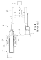
- Figure 1 illustrates a conventional thermal engine 1 disclosed in U.S. Patent No. 6,779,341 and including a first pneumatic cylinder 11, a second pneumatic cylinder 12, a fluid pipe 15 intercommunicating fluidly the first and second pneumatic cylinders 11, 12, and a flywheel assembly 13 coupled to the first and second pneumatic cylinders 11, 12.
- Thermal energy from a thermal energy source 2 is applied to a cylinder body 111 of the first pneumatic cylinder 11 to result in an expansion stroke of the first pneumatic cylinder 11 and in rotation of the flywheel assembly 13.
- the expansion stroke of the first pneumatic cylinder 11 also results in a compression stroke of the second pneumatic cylinder 12.
- a mechanical power output generated by the conventional thermal engine 1 depends on the thermal energy generated by the thermal energy source 2.
- the thermal energy is generated from solar energy or terrestrial heat, unstable supply of the thermal energy to the first pneumatic cylinder 11 may occur.
- the thermal energy is generated by fuel combustion, in order to ensure stable supply of the thermal energy to the first pneumatic cylinder 11, continuous supply of fuel is necessary, thereby resulting in relatively high costs.
- an object of the present invention is to provide a fuel gas generator that has enhanced electric generating efficiency at relatively low costs.
- a fuel gas generator comprises:
- the flow valve is controlled by the controller to switch from the ON state to the OFF state upon detecting that the temperature in the combustion chamber is higher than a predetermined first temperature and to switch from the OFF state to the ON state upon detecting that the temperature in the combustion chamber is lower than a predetermined second temperature that is lower than the predetermined first temperature.
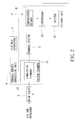
- a fuel gas generator according to the present invention is shown to include a thermal engine 3, a thermal energy generating unit 4, a flow valve 5, a control unit 6, and an electric generator 7.
- the thermal energy generating unit 4 includes a combustion chamber 41 and a vacuum chamber 42.
- the combustion chamber 41 is in thermal contact with the thermal engine 3 for generating thermal energy through combustion of air and fuel gas supplied thereto and for supplying the thermal energy to the thermal engine 3 such that the thermal engine 3 is driven to generate kinetic energy.
- the fuel gas includes hydrogen such that a combustion product is water, thereby conforming to requirements for environmental protection.
- the combustion product can be discharged via a discharge passage (not shown) in spatial communication with the combustion chamber 41.
- the fuel gas can be a hydrocarbon or natural gas.
- the vacuum chamber 42 surrounds the combustion chamber 41. It is noted that, due to the presence of the vacuum chamber 42, heat dissipation from the combustion chamber 41 can be minimized, thereby ensuring a superior thermal energy generating efficiency of the thermal energy generating unit 4.
- the electric generator 7 is coupled to the thermal engine 3 for converting the kinetic energy generated thereby into electrical energy.
- the flow valve 5 is coupled to the combustion chamber 41 of the thermal energy generating unit 4, and is operable to control supply of the air and the fuel gas to the combustion chamber 41 of the thermal energy generating unit 4.
- the control unit 6 includes a temperature sensor 61, an igniter 62 and a controller 63.
- the temperature sensor 61 senses a temperature in the combustion chamber 41 of the thermal energy generating unit 4, and generates a sensing signal indicative of the temperature in the combustion chamber 41.
- the igniter 62 is disposed in the combustion chamber 41, and is operable to ignite the fuel gas in the combustion chamber 41.
- the controller 63 is coupled to the temperature sensor 61, the igniter 62 and the flow valve 5, and receives the sensing signal from the temperature sensor 61.
- the controller 63 controls the flow valve 5 based on the sensing signal received thereby such that the flow valve 5 is operable between an ON-state, where the air and the fuel are supplied to the combustion chamber 41 of the thermal energy generating unit 4 through the flow valve 5, and an OFF-state, where supply of the air and the fuel gas to the combustion chamber 41 of the thermal energy generating unit 4 is ceased.
- the flow valve 5 is controlled by the controller 63 of the control unit 6 to switch from the ON-state to the OFF-state upon detecting that the temperature in the combustion chamber 41 of the thermal energy generating unit 4 is higher than a predetermined first temperature (T1), and to switch from the OFF-state to the ON-state upon detecting that the temperature in the combustion chamber 41 of the thermal energy generating unit 4 is lower than a predetermined second temperature (T2) that is lower than the predetermined first temperature (T1), i.e., T1 > T2.
- T1 predetermined first temperature
- the vacuum chamber 42 of the thermal energy generating unit 4 can ensure a superior thermal energy generating efficiency of the thermal energy generating unit 4 and since the air and the fuel gas are supplied intermittingly to the combustion chamber 41 of the thermal energy generating unit 4 through control of the flow valve 5, the temperature in the combustion chamber 41 of the thermal energy generating unit 4 can be maintained at the predetermined second temperature (T2) with a relatively small amount of the fuel gas.
- T2 predetermined second temperature
- stable kinetic energy can be generated by the thermal engine 3 at relatively low fuel costs. Therefore, the fuel gas generator of the present invention can attain required electric generating effect and ensure stable electric generation at relatively low costs.
Landscapes
- Engineering & Computer Science (AREA)
- Chemical & Material Sciences (AREA)
- Combustion & Propulsion (AREA)
- Mechanical Engineering (AREA)
- General Engineering & Computer Science (AREA)
- Combustion Methods Of Internal-Combustion Engines (AREA)
- Output Control And Ontrol Of Special Type Engine (AREA)
Abstract
A fuel gas generator includes: a combustion chamber (41) generating thermal energy through combustion of air and fuel gas therein, and supplying the thermal energy to a thermal engine (3) such that the thermal engine (3) is driven to generate kinetic energy that is converted into electrical energy by an electric generator (7); a temperature sensor (61) for generating a sensing signal indicative of a temperature in the combustion chamber (41); and a controller (63) for controlling a flow valve (5) coupled to the combustion chamber (41) based on the sensing signal such that the f low valve (5) is switched to an OFF-state upon detecting that the temperature is higher than a first temperature (T1), thereby supplying the air and the fuel gas to the combustion chamber (41) therethrough, and to an ON-state upon detecting that the temperature is lower than a second temperature (T2) lower than the first temperature (T1), thereby ceasing supply of the air and the fuel gas to the combustion chamber (41).
Description
- The invention relates to a generator, more particularly to a fuel gas generator.
-
Figure 1 illustrates a conventionalthermal engine 1 disclosed inU.S. Patent No. 6,779,341 and including a firstpneumatic cylinder 11, a secondpneumatic cylinder 12, afluid pipe 15 intercommunicating fluidly the first and secondpneumatic cylinders flywheel assembly 13 coupled to the first and secondpneumatic cylinders thermal energy source 2 is applied to acylinder body 111 of the firstpneumatic cylinder 11 to result in an expansion stroke of the firstpneumatic cylinder 11 and in rotation of theflywheel assembly 13. The expansion stroke of the firstpneumatic cylinder 11 also results in a compression stroke of the secondpneumatic cylinder 12. When the firstpneumatic cylinder 11 reaches the end of the expansion stroke, due to the presence of thefluid pipe 15, temperature of working gas in the firstpneumatic cylinder 11 is reduced, while temperature of working gas in the secondpneumatic cylinder 12 is increased, thereby resulting in an expansion stroke of the secondpneumatic cylinder 12 and in continued rotation of theflywheel assembly 13. Similarly, the expansion stroke of the secondpneumatic cylinder 12 results in a compression stroke of the firstpneumatic cylinder 11. Accordingly, continuous rotation of theflywheel assembly 13 is achieved such that kinetic energy is generated from thermal energy and that the kinetic energy is converted into electrical energy by anelectric generator 14. - In such a configuration, a mechanical power output generated by the conventional
thermal engine 1 depends on the thermal energy generated by thethermal energy source 2. When the thermal energy is generated from solar energy or terrestrial heat, unstable supply of the thermal energy to the firstpneumatic cylinder 11 may occur. When the thermal energy is generated by fuel combustion, in order to ensure stable supply of the thermal energy to the firstpneumatic cylinder 11, continuous supply of fuel is necessary, thereby resulting in relatively high costs. - Therefore, an object of the present invention is to provide a fuel gas generator that has enhanced electric generating efficiency at relatively low costs.
- According to the present invention, a fuel gas generator comprises:
- a thermal engine;
- a thermal energy generating unit including
- a combustion chamber in thermal contact with the thermal engine for generating thermal energy through combustion of air and fuel gas supplied thereto and for supplying the thermal energy to the thermal engine such that the thermal engine is driven to generate kinetic energy;
- an electric generator coupled to the thermal engine for converting the kinetic energy generated thereby into electrical energy;
- a flow valve coupled to the combustion chamber and operable to control supply of the air and the fuel gas to the combustion chamber; and
- a control unit including
- a temperature sensor for generating a sensing signal indicative of a temperature in the combustion chamber of the thermal energy supplying unit, and
- a controller coupled to the temperature sensor and the flow valve, receiving the sensing signal from the temperature sensor, and controlling the flow valve based on the sensing signal received thereby such that the flow valve is operable between an ON state, where the air and the fuel gas are supplied to the combustion chamber through the flow valve, and an OFF state, where supply of the air and the fuel gas to the combustion chamber is ceased.
- The flow valve is controlled by the controller to switch from the ON state to the OFF state upon detecting that the temperature in the combustion chamber is higher than a predetermined first temperature and to switch from the OFF state to the ON state upon detecting that the temperature in the combustion chamber is lower than a predetermined second temperature that is lower than the predetermined first temperature.
- Other features and advantages of the present invention will become apparent in the following detailed description of the preferred embodiment with reference to the accompanying drawings, of which:
-
Figure 1 is a partly sectional, schematic top view showing a conventional thermal engine disclosed inU.S. Patent No. 6,779,341 ; and -
Figure 2 is a schematic circuit block diagram showing the preferred embodiment of a fuel gas generator according to the present invention. - Referring to
Figure 2 , the preferred embodiment of a fuel gas generator according to the present invention is shown to include athermal engine 3, a thermal energy generating unit 4, aflow valve 5, acontrol unit 6, and anelectric generator 7. - The thermal energy generating unit 4 includes a
combustion chamber 41 and avacuum chamber 42. Thecombustion chamber 41 is in thermal contact with thethermal engine 3 for generating thermal energy through combustion of air and fuel gas supplied thereto and for supplying the thermal energy to thethermal engine 3 such that thethermal engine 3 is driven to generate kinetic energy. In this embodiment, the fuel gas includes hydrogen such that a combustion product is water, thereby conforming to requirements for environmental protection. The combustion product can be discharged via a discharge passage (not shown) in spatial communication with thecombustion chamber 41. In other embodiments, the fuel gas can be a hydrocarbon or natural gas. - The
vacuum chamber 42 surrounds thecombustion chamber 41. It is noted that, due to the presence of thevacuum chamber 42, heat dissipation from thecombustion chamber 41 can be minimized, thereby ensuring a superior thermal energy generating efficiency of the thermal energy generating unit 4. - The
electric generator 7 is coupled to thethermal engine 3 for converting the kinetic energy generated thereby into electrical energy. - The
flow valve 5 is coupled to thecombustion chamber 41 of the thermal energy generating unit 4, and is operable to control supply of the air and the fuel gas to thecombustion chamber 41 of the thermal energy generating unit 4. - The
control unit 6 includes atemperature sensor 61, anigniter 62 and acontroller 63. Thetemperature sensor 61 senses a temperature in thecombustion chamber 41 of the thermal energy generating unit 4, and generates a sensing signal indicative of the temperature in thecombustion chamber 41. Theigniter 62 is disposed in thecombustion chamber 41, and is operable to ignite the fuel gas in thecombustion chamber 41. Thecontroller 63 is coupled to thetemperature sensor 61, theigniter 62 and theflow valve 5, and receives the sensing signal from thetemperature sensor 61. Thecontroller 63 controls theflow valve 5 based on the sensing signal received thereby such that theflow valve 5 is operable between an ON-state, where the air and the fuel are supplied to thecombustion chamber 41 of the thermal energy generating unit 4 through theflow valve 5, and an OFF-state, where supply of the air and the fuel gas to thecombustion chamber 41 of the thermal energy generating unit 4 is ceased. Thus, theflow valve 5 is controlled by thecontroller 63 of thecontrol unit 6 to switch from the ON-state to the OFF-state upon detecting that the temperature in thecombustion chamber 41 of the thermal energy generating unit 4 is higher than a predetermined first temperature (T1), and to switch from the OFF-state to the ON-state upon detecting that the temperature in thecombustion chamber 41 of the thermal energy generating unit 4 is lower than a predetermined second temperature (T2) that is lower than the predetermined first temperature (T1), i.e., T1 > T2. When theflow valve 5 is switched from the OFF-state to the ON-state, theigniter 62 is activated through control of thecontroller 63 to ignite the fuel gas in thecombustion chamber 41 of the thermal energy generating unit 4. - In sum, since the
vacuum chamber 42 of the thermal energy generating unit 4 can ensure a superior thermal energy generating efficiency of the thermal energy generating unit 4 and since the air and the fuel gas are supplied intermittingly to thecombustion chamber 41 of the thermal energy generating unit 4 through control of theflow valve 5, the temperature in thecombustion chamber 41 of the thermal energy generating unit 4 can be maintained at the predetermined second temperature (T2) with a relatively small amount of the fuel gas. Thus, stable kinetic energy can be generated by thethermal engine 3 at relatively low fuel costs. Therefore, the fuel gas generator of the present invention can attain required electric generating effect and ensure stable electric generation at relatively low costs.
Claims (2)
- A fuel gas generator characterized by:a thermal engine (3);a thermal energy generating unit (4) including
a combustion chamber (41) in thermal contact with said thermal engine (3) for generating thermal energy through combustion of air and fuel gas supplied thereto and for supplying the thermal energy to said thermal engine (3) such that said thermal engine (3) is driven to generate kinetic energy;an electric generator (7) coupled to said thermal engine (3) for converting the kinetic energy generated thereby into electrical energy;a flow valve (5) coupled to said combustion chamber (41) and operable to control supply of the air and the fuel gas to said combustion chamber (41); anda control unit (6) including
a temperature sensor (61) for generating a sensing signal indicative of a temperature in said combustion chamber (41) of said thermal energy supplying unit (4), and
a controller (63) coupled to said temperature sensor (61) and said flow valve (5), receiving the sensing signal from said temperature sensor, and controlling said flow valve (5) based on the sensing signal received thereby such that said flow valve (5) is operable between an ON-state, where the air and the fuel gas are supplied to said combustion chamber (41) through said flow valve (5), and an OFF-state, where supply of the air and the fuel gas to said combustion chamber (41) is ceased;wherein said flow valve (5) is controlled by said controller (63) to switch from the ON-state to the OFF-state upon detecting that the temperature in said combustion chamber (41) is higher than a predetermined first temperature (T1) and to switch from the OFF-state to the ON-state upon detecting that the temperature in said combustion chamber (41) is lower than a predetermined second temperature (T2) that is lower than the predetermined first temperature (T1). - The fuel gas generator as claimed in Claim 1, characterized in that said thermal energy generating unit (4) further includes a vacuum chamber (42) surrounding said combustion chamber (41).
Applications Claiming Priority (2)
| Application Number | Priority Date | Filing Date | Title |
|---|---|---|---|
| TW98121623 | 2009-06-26 | ||
| TW098133167A TW201100628A (en) | 2009-06-26 | 2009-09-30 | Electricity generation device with fuel gas |
Publications (1)
| Publication Number | Publication Date |
|---|---|
| EP2267293A2 true EP2267293A2 (en) | 2010-12-29 |
Family
ID=43066996
Family Applications (1)
| Application Number | Title | Priority Date | Filing Date |
|---|---|---|---|
| EP10160688A Withdrawn EP2267293A2 (en) | 2009-06-26 | 2010-04-22 | Fuel gas generator |
Country Status (3)
| Country | Link |
|---|---|
| US (1) | US20100327587A1 (en) |
| EP (1) | EP2267293A2 (en) |
| TW (1) | TW201100628A (en) |
Cited By (1)
| Publication number | Priority date | Publication date | Assignee | Title |
|---|---|---|---|---|
| CN106553611A (en) * | 2015-09-30 | 2017-04-05 | 丰田合成株式会社 | Inflator |
Families Citing this family (3)
| Publication number | Priority date | Publication date | Assignee | Title |
|---|---|---|---|---|
| US9665077B2 (en) * | 2013-12-18 | 2017-05-30 | General Electric Company | Gas turbine firing temperature control system and method |
| CN105840346A (en) * | 2016-03-29 | 2016-08-10 | 成都科力夫科技有限公司 | Injection method of automobile gas fuel injection system |
| US20180128313A1 (en) * | 2016-11-07 | 2018-05-10 | Cleveland State University | Active radial magnetic bearing phased array |
Citations (1)
| Publication number | Priority date | Publication date | Assignee | Title |
|---|---|---|---|---|
| US6779341B2 (en) | 2002-06-19 | 2004-08-24 | Chin-Kuang Luo | Method and apparatus for generating kinetic energy from thermal energy |
Family Cites Families (8)
| Publication number | Priority date | Publication date | Assignee | Title |
|---|---|---|---|---|
| GB2132692A (en) * | 1982-12-24 | 1984-07-11 | Ford Motor Co | Intake manifold for an internal combustion engine |
| JPS60122255A (en) * | 1983-12-07 | 1985-06-29 | Aisin Seiki Co Ltd | Temperature controlling device for stirling engine |
| US4630447A (en) * | 1985-12-26 | 1986-12-23 | Webber William T | Regenerated internal combustion engine |
| US5077976A (en) * | 1990-08-22 | 1992-01-07 | Pavo Pusic | Stirling engine using hydraulic connecting rod |
| US6301893B1 (en) * | 2000-10-20 | 2001-10-16 | Orra Corporation | Method and apparatus for converting natural heat energy into another form of energy |
| GB0130530D0 (en) * | 2001-12-20 | 2002-02-06 | Bg Intellectual Pty Ltd | A domestic combined heat and power unit |
| TWI230245B (en) * | 2002-06-13 | 2005-04-01 | Jiun-Guang Luo | Vacuum superconductive solar heat collector |
| TWM350608U (en) * | 2008-09-22 | 2009-02-11 | Active Technology Engineering Inc | Temperature-controlled fuel-supplying device for combustion machine |
-
2009
- 2009-09-30 TW TW098133167A patent/TW201100628A/en not_active IP Right Cessation
- 2009-12-16 US US12/639,981 patent/US20100327587A1/en not_active Abandoned
-
2010
- 2010-04-22 EP EP10160688A patent/EP2267293A2/en not_active Withdrawn
Patent Citations (1)
| Publication number | Priority date | Publication date | Assignee | Title |
|---|---|---|---|---|
| US6779341B2 (en) | 2002-06-19 | 2004-08-24 | Chin-Kuang Luo | Method and apparatus for generating kinetic energy from thermal energy |
Cited By (3)
| Publication number | Priority date | Publication date | Assignee | Title |
|---|---|---|---|---|
| CN106553611A (en) * | 2015-09-30 | 2017-04-05 | 丰田合成株式会社 | Inflator |
| US10005420B2 (en) * | 2015-09-30 | 2018-06-26 | Toyoda Gosei Co., Ltd. | Inflator |
| CN106553611B (en) * | 2015-09-30 | 2018-12-25 | 丰田合成株式会社 | Inflator |
Also Published As
| Publication number | Publication date |
|---|---|
| TW201100628A (en) | 2011-01-01 |
| TWI384121B (en) | 2013-02-01 |
| US20100327587A1 (en) | 2010-12-30 |
Similar Documents
| Publication | Publication Date | Title |
|---|---|---|
| KR101422990B1 (en) | Power plant facility, ship provided with same, and method for operating power plant facility | |
| EP2267293A2 (en) | Fuel gas generator | |
| AU2003263704A1 (en) | Energy converter | |
| SI1649144T1 (en) | Electrical power generation system and method | |
| CA2390221A1 (en) | Fuel cell operation method | |
| WO2010049944A1 (en) | Hydrogen carburetor for generating hydrogen to run an internal combustion engine and method thereof | |
| RU2009137121A (en) | GAS-TURBINE SYSTEM OF ELECTRIC POWER PRODUCTION AND METHOD OF MANAGING ITS OPERATION | |
| EP1270310A3 (en) | Control device for fuel cell vehicle | |
| US7327047B2 (en) | Gas turbine engine generator system | |
| EP1416562A3 (en) | Fuel cell system | |
| KR100735617B1 (en) | Thermoelectric generator using waste heat | |
| CN104564438A (en) | High-thermal-efficiency alcohol generator unit | |
| KR20110000496A (en) | Fuel gas generator | |
| WO2009021729A3 (en) | Heat engine | |
| JP2013170454A (en) | Device and method for heating of stirling engine | |
| JP2016146679A (en) | Electric power supply system | |
| US20100063707A1 (en) | Control method and device for a thermal engine | |
| DE10345580A1 (en) | Device for generating heat and current has electrically controllable temperature, pressure and mass flow of working medium to enable demand-matching variable thermal output coupling to different temperature levels | |
| CN101985902A (en) | Steamer generating equipment capable of heating by automobile exhaust | |
| KR20110064978A (en) | Thermoelectric generation system for heat recovery of automobile | |
| US7798810B2 (en) | High pressure hot gas generating device | |
| CN112302734A (en) | Power generation system | |
| US20060192388A1 (en) | Boiler driving power supply system | |
| KR100624735B1 (en) | Cogeneration System | |
| WO2006060695A3 (en) | Dynamic mass transfer rapid response power conversion |
Legal Events
| Date | Code | Title | Description |
|---|---|---|---|
| PUAI | Public reference made under article 153(3) epc to a published international application that has entered the european phase |
Free format text: ORIGINAL CODE: 0009012 |
|
| AK | Designated contracting states |
Kind code of ref document: A2 Designated state(s): AT BE BG CH CY CZ DE DK EE ES FI FR GB GR HR HU IE IS IT LI LT LU LV MC MK MT NL NO PL PT RO SE SI SK SM TR |
|
| AX | Request for extension of the european patent |
Extension state: AL BA ME RS |
|
| STAA | Information on the status of an ep patent application or granted ep patent |
Free format text: STATUS: THE APPLICATION HAS BEEN WITHDRAWN |
|
| 18W | Application withdrawn |
Effective date: 20120305 |