EP2266905A1 - Media transport mechanism - Google Patents
Media transport mechanism Download PDFInfo
- Publication number
- EP2266905A1 EP2266905A1 EP10162350A EP10162350A EP2266905A1 EP 2266905 A1 EP2266905 A1 EP 2266905A1 EP 10162350 A EP10162350 A EP 10162350A EP 10162350 A EP10162350 A EP 10162350A EP 2266905 A1 EP2266905 A1 EP 2266905A1
- Authority
- EP
- European Patent Office
- Prior art keywords
- media
- length
- arcuate
- store
- entrance
- Prior art date
- Legal status (The legal status is an assumption and is not a legal conclusion. Google has not performed a legal analysis and makes no representation as to the accuracy of the status listed.)
- Granted
Links
Images

Classifications
-
- B—PERFORMING OPERATIONS; TRANSPORTING
- B65—CONVEYING; PACKING; STORING; HANDLING THIN OR FILAMENTARY MATERIAL
- B65H—HANDLING THIN OR FILAMENTARY MATERIAL, e.g. SHEETS, WEBS, CABLES
- B65H29/00—Delivering or advancing articles from machines; Advancing articles to or into piles
- B65H29/006—Winding articles into rolls
- B65H29/008—Winding single articles into single rolls
-
- B—PERFORMING OPERATIONS; TRANSPORTING
- B65—CONVEYING; PACKING; STORING; HANDLING THIN OR FILAMENTARY MATERIAL
- B65H—HANDLING THIN OR FILAMENTARY MATERIAL, e.g. SHEETS, WEBS, CABLES
- B65H15/00—Overturning articles
- B65H15/004—Overturning articles employing rollers
-
- B—PERFORMING OPERATIONS; TRANSPORTING
- B65—CONVEYING; PACKING; STORING; HANDLING THIN OR FILAMENTARY MATERIAL
- B65H—HANDLING THIN OR FILAMENTARY MATERIAL, e.g. SHEETS, WEBS, CABLES
- B65H29/00—Delivering or advancing articles from machines; Advancing articles to or into piles
- B65H29/12—Delivering or advancing articles from machines; Advancing articles to or into piles by means of the nip between two, or between two sets of, moving tapes or bands or rollers
-
- B—PERFORMING OPERATIONS; TRANSPORTING
- B65—CONVEYING; PACKING; STORING; HANDLING THIN OR FILAMENTARY MATERIAL
- B65H—HANDLING THIN OR FILAMENTARY MATERIAL, e.g. SHEETS, WEBS, CABLES
- B65H29/00—Delivering or advancing articles from machines; Advancing articles to or into piles
- B65H29/58—Article switches or diverters
- B65H29/60—Article switches or diverters diverting the stream into alternative paths
-
- G—PHYSICS
- G07—CHECKING-DEVICES
- G07B—TICKET-ISSUING APPARATUS; FARE-REGISTERING APPARATUS; FRANKING APPARATUS
- G07B1/00—Machines for printing and issuing tickets
-
- G—PHYSICS
- G07—CHECKING-DEVICES
- G07G—REGISTERING THE RECEIPT OF CASH, VALUABLES, OR TOKENS
- G07G5/00—Receipt-giving machines
-
- B—PERFORMING OPERATIONS; TRANSPORTING
- B65—CONVEYING; PACKING; STORING; HANDLING THIN OR FILAMENTARY MATERIAL
- B65H—HANDLING THIN OR FILAMENTARY MATERIAL, e.g. SHEETS, WEBS, CABLES
- B65H2301/00—Handling processes for sheets or webs
- B65H2301/30—Orientation, displacement, position of the handled material
- B65H2301/33—Modifying, selecting, changing orientation
- B65H2301/333—Inverting
- B65H2301/3331—Involving forward reverse transporting means
- B65H2301/33312—Involving forward reverse transporting means forward reverse rollers pairs
-
- B—PERFORMING OPERATIONS; TRANSPORTING
- B65—CONVEYING; PACKING; STORING; HANDLING THIN OR FILAMENTARY MATERIAL
- B65H—HANDLING THIN OR FILAMENTARY MATERIAL, e.g. SHEETS, WEBS, CABLES
- B65H2301/00—Handling processes for sheets or webs
- B65H2301/40—Type of handling process
- B65H2301/41—Winding, unwinding
- B65H2301/419—Winding, unwinding from or to storage, i.e. the storage integrating winding or unwinding means
- B65H2301/4191—Winding, unwinding from or to storage, i.e. the storage integrating winding or unwinding means for handling articles of limited length, e.g. AO format, arranged at intervals from each other
-
- B—PERFORMING OPERATIONS; TRANSPORTING
- B65—CONVEYING; PACKING; STORING; HANDLING THIN OR FILAMENTARY MATERIAL
- B65H—HANDLING THIN OR FILAMENTARY MATERIAL, e.g. SHEETS, WEBS, CABLES
- B65H2301/00—Handling processes for sheets or webs
- B65H2301/40—Type of handling process
- B65H2301/44—Moving, forwarding, guiding material
- B65H2301/443—Moving, forwarding, guiding material by acting on surface of handled material
- B65H2301/4431—Moving, forwarding, guiding material by acting on surface of handled material by means with operating surfaces contacting opposite faces of material
- B65H2301/44318—Moving, forwarding, guiding material by acting on surface of handled material by means with operating surfaces contacting opposite faces of material between rollers
-
- B—PERFORMING OPERATIONS; TRANSPORTING
- B65—CONVEYING; PACKING; STORING; HANDLING THIN OR FILAMENTARY MATERIAL
- B65H—HANDLING THIN OR FILAMENTARY MATERIAL, e.g. SHEETS, WEBS, CABLES
- B65H2404/00—Parts for transporting or guiding the handled material
- B65H2404/60—Other elements in face contact with handled material
- B65H2404/61—Longitudinally-extending strips, tubes, plates, or wires
- B65H2404/611—Longitudinally-extending strips, tubes, plates, or wires arranged to form a channel
- B65H2404/6111—Longitudinally-extending strips, tubes, plates, or wires arranged to form a channel and shaped for curvilinear transport path
-
- B—PERFORMING OPERATIONS; TRANSPORTING
- B65—CONVEYING; PACKING; STORING; HANDLING THIN OR FILAMENTARY MATERIAL
- B65H—HANDLING THIN OR FILAMENTARY MATERIAL, e.g. SHEETS, WEBS, CABLES
- B65H2408/00—Specific machines
- B65H2408/10—Specific machines for handling sheet(s)
- B65H2408/13—Wall or kiosk dispenser, i.e. for positively handling or holding material until withdrawal by user
Definitions
- the present invention relates to media transport.
- the invention has application to printer transport mechanisms.
- Printers are commonly used in self-service terminals (SSTs), such as automated teller machines (ATMs), to provide a customer with a receipt, a statement, or some other printed document.
- SSTs self-service terminals
- ATMs automated teller machines
- the invention generally provides methods, systems, and apparatus for an improved media transport.
- a media transport comprising a media entrance for receiving a length of media; an arcuate media store for storing the length of media in a coiled configuration; a media exit through which the length of media can be presented; and a drive mechanism operable in a first direction to drive the length of media from the entrance into the arcuate media store, and in a second direction to drive the length of media from the entrance through the media exit for presentation to a user.
- the media transport may be a printer transport.
- the media entrance may receive a length of paper from a print engine.
- the arcuate media store may be a drum-shaped store.
- the media transport may include an arcuate guide extending from the media exit to near the media entrance.
- the arcuate guide may include a resilient diverter that is biased upwards, so that, during use, the diverter is urged downwards by media as it passes over the diverter to the drive mechanism, but deflects the media into the arcuate guide when the drive mechanism is reversed.
- the arcuate guide may include an opening portion for facilitating insertion of the length of media from the media entrance.
- the arcuate guide may include a funnel opening portion for facilitating insertion of the length of media from the media entrance.
- the arcuate guide may define a tapered channel for guiding the length of media to the media exit.
- the tapered channel may be wider at the entrance than at the media exit.
- the drive mechanism may comprise a roller co-operating with a skid plate, a pair of rollers, a pair of endless belts, a belt co-operating with a roller, a gear train, or the like.
- the roller may comprise a wheel, a drum, a polygon, or the like.
- the roller may have a circumference that is discontinuous (stepped) or continuous.
- a method of presenting media to a user comprising: receiving a length of media from an engine; driving the received length of media into a store to form an arcuate length of stored media; and driving the arcuate length of stored media out from the media store and into an arcuate guide to present the length of media to a user once the length of media has been discharged from the engine.
- a printer transport comprising a media entrance for receiving a length of media; an arcuate media store for storing the length of media in a coiled configuration; a media exit through which the length of media can be presented; and a drive mechanism operable in a first direction to drive the length of media from the entrance into the arcuate media store, and in a second direction to drive the length of media from the entrance through the media exit for presentation to a user.
- a printer including the transport of the third or first aspects.
- a self-service terminal including the transport of the third or first aspects.
- the self-service terminal may be an automated teller machine (ATM), an information kiosk, a financial services center, a bill payment kiosk, a lottery kiosk, a postal services machine, a check-in and/or check-out terminal such as those used in the retail, hotel, car rental, gaming, healthcare, and airline industries, or the like.
- ATM automated teller machine
- information kiosk a financial services center
- bill payment kiosk a bill payment kiosk
- lottery kiosk a lottery kiosk
- postal services machine a check-in and/or check-out terminal such as those used in the retail, hotel, car rental, gaming, healthcare, and airline industries, or the like.
- a method of presenting media to a user comprising: receiving a length of media from an engine; driving the received length of media into a store to form an arcuate length of stored media; discharging the length of media from the engine; and driving the arcuate length of stored media out from the media store and into an arcuate guide to present the length of media to a user.
- a seventh aspect there is provided a method of retrofitting a printer, the method comprising providing the printer with a media transport according to the first or third aspects of the invention.
- a controller programmed to implement the steps of the second aspect.
- some of these aspects have the advantage that media is moved out of a print engine prior to being presented to a user, so that it is not possible for the user to pull the media out of the print engine while the print engine is still printing on the media. This stops the user from disrupting printing by the print engine.
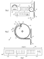
- Fig 1 is a simplified schematic diagram of a printer 10 according to one embodiment of the present invention.
- the printer 10 comprises a paper hopper 12 storing a roll 14 of paper 16; a print engine 18 supplied with paper 16 from the roll 14; a paper transport 20; and a printer controller 22.
- the printer controller 22 includes a processor 24 and a communications facility 26 (such as a USB port or an RS 232 port) for communicating with an ATM controller (not shown).
- the printer controller 22 receives commands and print data and from the ATM controller (not shown) and sends messages to the ATM controller (not shown) to indicate: that a print task was completed successfully, the status of components within the printer 10 (for example, if the paper roll 14 is nearly finished), and the like.
- the paper transport 20 comprises: an arcuate store 30 (in the form of a generally drum-shaped receptacle); a drive mechanism 34 at the entrance 36 of the arcuate store 30; and an arcuate guide 38.
- the arcuate guide 38 comprises (i) a diverter portion 39 near the entrance 36 and (ii) sidewalls 40a,b leading from the vicinity of the entrance 36 to a receipt aperture 42 defined by a fascia 44 in a self-service terminal (not shown).
- the sidewalls 40 define a channel 45 that tapers from the vicinity of the entrance 36 to the receipt aperture 42.
- One sidewall 40b is provided by an external wall of the arcuate store 30.
- the drive mechanism 34 comprises a retractable upper roller 46 and a fixed lower roller 48, spaced apart to co-operate in driving a length of receipt paper 16 into and out of the arcuate store 30.
- the upper roller 46 is driven by the printer controller 22, but the lower roller 48 is free to rotate as receipt paper 16 passes over it.
- the distance between the front end of the print engine 18 and the receipt aperture 42 is "d", illustrated by double headed arrow 50.
- "d" is approximately 8cm.
- a typical ATM receipt is approximately 11 cm long, but printer 10 is capable of printing and delivering receipts substantially longer than 11 cm (for example, 25cm).
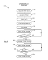
- Figs 3 to 5 are schematic diagrams illustrating the printer 10 with a printed receipt at different locations within the printer 10, and also with reference to Fig 6 , which is a flowchart 100 illustrating the operation of the printer 10.
- the printer controller 22 receives print data from the ATM controller (not shown) (step 110), which it uses to control the print engine 18 to advance paper (step 112) through a print head (not shown) in the print engine 18, while printing the received data onto the advancing paper 16 (step 114).
- the printer controller 22 starts the paper transport 20 (step 116) by driving the upper roller 46 anti-clockwise. As the printed paper 16 continues to advance, a leading edge 60 of the printed paper 16 pushes down the diverter portion 39 and is then nipped between the upper and lower rollers 46,48 and driven into the arcuate store 30 at the same speed as the paper is advanced. As the printed paper 16 enters the arcuate store 30, the printed paper 16 bends inwards, as illustrated in Fig 3 , due to the shape of the arcuate store 30 and the influence of gravity.
- the print engine 18 cuts the paper (step 118) to produce a printed receipt.
- the printer controller 22 continues to drive the upper roller 46 anti-clockwise (step 120) until a predetermined distance is reached (step 122), which is less than the distance between the cutting blade (not shown) in the print engine 18 and the drive mechanism 34 of the paper transport 20, but greater than the distance between the cutting blade (not shown) and the paper transport entrance 36. This is to ensure that when the upper roller 46 stops driving, a trailing edge 70 of the printed paper 16 protrudes from the drive mechanism 34 but is located within the paper transport 20. When this occurs, the bulk of the printed paper 16 is coiled (or spiralled) within the arcuate store 30, as illustrated in Fig 4 .
- the printer controller 22 then reverses the upper roller 46 (step 124) so that the upper and lower rollers 46,48 co-operate to drive the printed paper 16 (the receipt) out of the arcuate store 30, with the trailing edge 70 first (that is, the trailing edge 70 is now leading, and the leading edge 60 is now trailing).
- the trailing edge 70 (now leading) is driven downwards by the diverter portion 39 and is directed by the sidewalls 40 from the vicinity of the entrance 36 to the receipt aperture 42 defined by the fascia 44, as illustrated by Fig 5 .
- the arcuate guide 38 guides the trailing edge 70 towards the receipt aperture 42.
- the upper roller 46 is rotated until the receipt 16 is presented to a customer by protruding through the receipt aperture 42 by a predetermined distance (for example, the upper roller 46 may be driven until the trailing edge 70 protrudes by approximately 2cm to allow the customer to grasp the receipt 16 with his/her finger and thumb) (step 128).
- the controller 22 stops the upper roller 46 (step 130) to allow the customer to remove the receipt when he/she is ready to take it.
- the action of the customer pulling the receipt uncoils the receipt from the arcuate store 30 and causes the receipt to slide through the arcuate guide 38.
- a comparatively long receipt 200 such as that illustrated in Fig 7 , which has a length "L" of 25cm (illustrated by arrow 210) can be printed and presented to a customer in a controlled manner.
- the long receipt 200 includes three images of cheques 212,214,216 deposited at the ATM in a single transaction, in addition to transaction details 218. Because the receipt 200 is coiled within the arcuate store 30, it is possible to print variable length receipts, including comparatively long receipts, without risking jamming the printer 10 or a customer removing the receipt 16,200 before it has been printed.
- the drive mechanism may comprise a roller and a skid plate; endless belts and a skid plate; or any other convenient drive mechanism.
- the arcuate guide 38 may not be tapered.
- the arcuate store 30 may be rotatable to facilitate the trailing edge 70 entering the arcuate guide 38.
- the paper transport 20 may be used for transporting other types of media in a media handler other than a printer.
- the paper transport 20 may be retro-fitted to a conventional printer.
- an SST other than an ATM may be used to house the printer 10, for example, an information kiosk.
- the steps of the methods described herein may be carried out in any suitable order, or simultaneously where appropriate.
- the methods described herein may be performed by software in machine readable form on a tangible storage medium or as a propagating signal.
Landscapes
- Engineering & Computer Science (AREA)
- Mechanical Engineering (AREA)
- Physics & Mathematics (AREA)
- General Physics & Mathematics (AREA)
- Handling Of Sheets (AREA)
- Unwinding Webs (AREA)
- Cash Registers Or Receiving Machines (AREA)
Abstract
Description
- The present invention relates to media transport. In particular, though not exclusively, the invention has application to printer transport mechanisms.
- Printers are commonly used in self-service terminals (SSTs), such as automated teller machines (ATMs), to provide a customer with a receipt, a statement, or some other printed document.
- One problem associated with printers in a self-service environment is that a customer may attempt to remove a receipt prior to the receipt being completely printed. With short length receipts this is rare because a trailing edge of the receipt paper has cleared the print head prior to the leading edge of the receipt paper protruding through a receipt paper aperture in the SST fascia. However, where the receipt length exceeds the length of the transport mechanism, customers can pull the receipt prior to completion of printing. This can result in the receipt jamming or the receipt being removed with only part of the receipt data printed thereon.
- It is among the objects of an embodiment of the present invention to obviate or mitigate the above disadvantage or other disadvantages associated with prior art media transports.
- Accordingly, the invention generally provides methods, systems, and apparatus for an improved media transport.
- According to a first aspect there is provided a media transport comprising a media entrance for receiving a length of media; an arcuate media store for storing the length of media in a coiled configuration; a media exit through which the length of media can be presented; and a drive mechanism operable in a first direction to drive the length of media from the entrance into the arcuate media store, and in a second direction to drive the length of media from the entrance through the media exit for presentation to a user.
- The media transport may be a printer transport.
- The media entrance may receive a length of paper from a print engine.
- The arcuate media store may be a drum-shaped store.
- The media transport may include an arcuate guide extending from the media exit to near the media entrance.
- The arcuate guide may include a resilient diverter that is biased upwards, so that, during use, the diverter is urged downwards by media as it passes over the diverter to the drive mechanism, but deflects the media into the arcuate guide when the drive mechanism is reversed.
- The arcuate guide may include an opening portion for facilitating insertion of the length of media from the media entrance.
- The arcuate guide may include a funnel opening portion for facilitating insertion of the length of media from the media entrance.
- The arcuate guide may define a tapered channel for guiding the length of media to the media exit. The tapered channel may be wider at the entrance than at the media exit.
- The drive mechanism may comprise a roller co-operating with a skid plate, a pair of rollers, a pair of endless belts, a belt co-operating with a roller, a gear train, or the like.
- The roller may comprise a wheel, a drum, a polygon, or the like. The roller may have a circumference that is discontinuous (stepped) or continuous.
- According to a second aspect there is provided a method of presenting media to a user, the method comprising: receiving a length of media from an engine; driving the received length of media into a store to form an arcuate length of stored media; and driving the arcuate length of stored media out from the media store and into an arcuate guide to present the length of media to a user once the length of media has been discharged from the engine.
- According to a third aspect there is provided a printer transport comprising a media entrance for receiving a length of media; an arcuate media store for storing the length of media in a coiled configuration; a media exit through which the length of media can be presented; and a drive mechanism operable in a first direction to drive the length of media from the entrance into the arcuate media store, and in a second direction to drive the length of media from the entrance through the media exit for presentation to a user.
- According to a fourth aspect there is provided a printer including the transport of the third or first aspects.
- According to a fifth aspect there is provided a self-service terminal including the transport of the third or first aspects.
- The self-service terminal may be an automated teller machine (ATM), an information kiosk, a financial services center, a bill payment kiosk, a lottery kiosk, a postal services machine, a check-in and/or check-out terminal such as those used in the retail, hotel, car rental, gaming, healthcare, and airline industries, or the like.
- According to a sixth aspect there is provided a method of presenting media to a user, the method comprising: receiving a length of media from an engine; driving the received length of media into a store to form an arcuate length of stored media; discharging the length of media from the engine; and driving the arcuate length of stored media out from the media store and into an arcuate guide to present the length of media to a user.
- According to a seventh aspect there is provided a method of retrofitting a printer, the method comprising providing the printer with a media transport according to the first or third aspects of the invention.
- According to an eighth aspect there is provided a controller programmed to implement the steps of the second aspect.
- When applied to a printer, some of these aspects have the advantage that media is moved out of a print engine prior to being presented to a user, so that it is not possible for the user to pull the media out of the print engine while the print engine is still printing on the media. This stops the user from disrupting printing by the print engine.
- These and other aspects will be apparent from the following specific description, given by way of example, with reference to the accompanying drawings, in which:
-
Fig 1 is a simplified schematic diagram of a printer according to one embodiment of the present invention; -
Fig 2 is a simplified schematic diagram of the printer ofFig 1 , showing a part thereof (the paper transport) in more detail; -
Fig 3 is a simplified schematic diagram of the printer ofFig 1 , showing receipt paper entering a part (the arcuate store) of the paper transport; -
Fig 4 is a simplified schematic diagram of the printer ofFig 1 , showing receipt paper exiting the arcuate store; -
Fig 5 is a simplified schematic diagram of the printer ofFig 1 , showing receipt paper exiting the paper transport and being presented to a customer; -
Fig 6 is a flowchart illustrating the steps involved in presenting the receipt paper to the customer; and -
Fig 7 is a pictorial diagram of a receipt printed by the printer ofFig 1 . - Reference is first made to
Fig 1 , which is a simplified schematic diagram of a printer 10 according to one embodiment of the present invention. The printer 10 comprises apaper hopper 12 storing aroll 14 ofpaper 16; aprint engine 18 supplied withpaper 16 from theroll 14; apaper transport 20; and aprinter controller 22. - The
printer controller 22 includes aprocessor 24 and a communications facility 26 (such as a USB port or an RS 232 port) for communicating with an ATM controller (not shown). Theprinter controller 22 receives commands and print data and from the ATM controller (not shown) and sends messages to the ATM controller (not shown) to indicate: that a print task was completed successfully, the status of components within the printer 10 (for example, if thepaper roll 14 is nearly finished), and the like. - Reference is also made to
Fig 2 , which is a simplified schematic diagram showing thepaper transport 20 in more detail. Thepaper transport 20 comprises: an arcuate store 30 (in the form of a generally drum-shaped receptacle); adrive mechanism 34 at theentrance 36 of thearcuate store 30; and anarcuate guide 38. Thearcuate guide 38 comprises (i) adiverter portion 39 near theentrance 36 and (ii)sidewalls 40a,b leading from the vicinity of theentrance 36 to areceipt aperture 42 defined by afascia 44 in a self-service terminal (not shown). The sidewalls 40 define achannel 45 that tapers from the vicinity of theentrance 36 to thereceipt aperture 42. Onesidewall 40b is provided by an external wall of thearcuate store 30. - The
drive mechanism 34 comprises a retractableupper roller 46 and a fixedlower roller 48, spaced apart to co-operate in driving a length ofreceipt paper 16 into and out of thearcuate store 30. Theupper roller 46 is driven by theprinter controller 22, but thelower roller 48 is free to rotate asreceipt paper 16 passes over it. - The distance between the front end of the
print engine 18 and thereceipt aperture 42 is "d", illustrated by double headedarrow 50. In this embodiment, "d" is approximately 8cm. A typical ATM receipt is approximately 11 cm long, but printer 10 is capable of printing and delivering receipts substantially longer than 11 cm (for example, 25cm). - The operation of the printer 10 will now be described with reference to
Figs 3 to 5 , which are schematic diagrams illustrating the printer 10 with a printed receipt at different locations within the printer 10, and also with reference toFig 6 , which is aflowchart 100 illustrating the operation of the printer 10. - Initially, the
printer controller 22 receives print data from the ATM controller (not shown) (step 110), which it uses to control theprint engine 18 to advance paper (step 112) through a print head (not shown) in theprint engine 18, while printing the received data onto the advancing paper 16 (step 114). - The
printer controller 22 starts the paper transport 20 (step 116) by driving theupper roller 46 anti-clockwise. As the printedpaper 16 continues to advance, a leadingedge 60 of the printedpaper 16 pushes down thediverter portion 39 and is then nipped between the upper andlower rollers arcuate store 30 at the same speed as the paper is advanced. As the printedpaper 16 enters thearcuate store 30, the printedpaper 16 bends inwards, as illustrated inFig 3 , due to the shape of thearcuate store 30 and the influence of gravity. - When the
print engine 18 has completely printed thepaper 16, then theprint engine 18 cuts the paper (step 118) to produce a printed receipt. - The
printer controller 22 continues to drive theupper roller 46 anti-clockwise (step 120) until a predetermined distance is reached (step 122), which is less than the distance between the cutting blade (not shown) in theprint engine 18 and thedrive mechanism 34 of thepaper transport 20, but greater than the distance between the cutting blade (not shown) and thepaper transport entrance 36. This is to ensure that when theupper roller 46 stops driving, atrailing edge 70 of the printedpaper 16 protrudes from thedrive mechanism 34 but is located within thepaper transport 20. When this occurs, the bulk of the printedpaper 16 is coiled (or spiralled) within thearcuate store 30, as illustrated inFig 4 . - The
printer controller 22 then reverses the upper roller 46 (step 124) so that the upper andlower rollers arcuate store 30, with thetrailing edge 70 first (that is, thetrailing edge 70 is now leading, and the leadingedge 60 is now trailing). - As the
upper roller 46 rotates clockwise (step 126) the trailing edge 70 (now leading) is driven downwards by thediverter portion 39 and is directed by the sidewalls 40 from the vicinity of theentrance 36 to thereceipt aperture 42 defined by thefascia 44, as illustrated byFig 5 . Thus, thearcuate guide 38 guides the trailingedge 70 towards thereceipt aperture 42. - The
upper roller 46 is rotated until thereceipt 16 is presented to a customer by protruding through thereceipt aperture 42 by a predetermined distance (for example, theupper roller 46 may be driven until the trailingedge 70 protrudes by approximately 2cm to allow the customer to grasp thereceipt 16 with his/her finger and thumb) (step 128). - Once the
receipt 16 has been presented to the customer then thecontroller 22 stops the upper roller 46 (step 130) to allow the customer to remove the receipt when he/she is ready to take it. - The action of the customer pulling the receipt uncoils the receipt from the
arcuate store 30 and causes the receipt to slide through thearcuate guide 38. - By virtue of this embodiment of the present invention, a comparatively
long receipt 200, such as that illustrated inFig 7 , which has a length "L" of 25cm (illustrated by arrow 210) can be printed and presented to a customer in a controlled manner. Thelong receipt 200 includes three images of cheques 212,214,216 deposited at the ATM in a single transaction, in addition to transaction details 218. Because thereceipt 200 is coiled within thearcuate store 30, it is possible to print variable length receipts, including comparatively long receipts, without risking jamming the printer 10 or a customer removing the receipt 16,200 before it has been printed. - Various modifications may be made to the above described embodiment within the scope of the invention. For example, in other embodiments, the drive mechanism may comprise a roller and a skid plate; endless belts and a skid plate; or any other convenient drive mechanism.
- In other embodiments the
arcuate guide 38 may not be tapered. - In other embodiments, the
arcuate store 30 may be rotatable to facilitate the trailingedge 70 entering thearcuate guide 38. - In other embodiments, the
paper transport 20 may be used for transporting other types of media in a media handler other than a printer. - In other embodiments, the
paper transport 20 may be retro-fitted to a conventional printer. - In other embodiments, an SST other than an ATM may be used to house the printer 10, for example, an information kiosk.
- The steps of the methods described herein may be carried out in any suitable order, or simultaneously where appropriate. The methods described herein may be performed by software in machine readable form on a tangible storage medium or as a propagating signal.
- The terms "comprising", "including", "incorporating", and "having" are used herein to recite an open-ended list of one or more elements or steps, not a closed list. When such terms are used, those elements or steps recited in the list are not exclusive of other elements or steps that may be added to the list.
Claims (11)
- A media transport (20) comprising:a media entrance (36) for receiving a length of media (16);an arcuate media store (30) for storing the length of media (16) in a coiled configuration;a media exit through which the length of media (16) can be presented; anda drive mechanism (34) operable in a first direction to drive the length of media (16) from the entrance (36) into the arcuate media store (30), and in a second direction to drive the length of media (16) from the entrance (36) through the media exit for presentation to a user.
- A media transport according to claim 1, wherein the media transport (20) conveys paper.
- A media transport according to claim 1 or 2, wherein the arcuate media store (30) is generally drum-shaped.
- A media transport according to any of claims 1 to 3, further comprising an arcuate guide (38) extending from the media exit to near the media entrance (36).
- A media transport according to claim 4, wherein the arcuate guide (38) includes a diverter (39) for facilitating insertion of the length of media (16) from the media entrance (36).
- A media transport according to claim 4 or 5, wherein the arcuate guide (38) includes a tapered channel (45) for guiding the length of media (16) to the media exit.
- A media transport according to any preceding claim, wherein the drive mechanism (34) comprises at least one of: a roller co-operating with a skid plate; a pair of rollers; a pair of endless belts; an endless belt co-operating with a roller; and a gear train.
- A media transport according to any of claims 1 to 6, wherein the drive mechanism (34) comprises a pair of rollers.
- A printer (10) including the media transport (20) of any preceding claim.
- A method of presenting media to a user, the method comprising:receiving a length of media from an engine;driving the received length of media into a store to form an arcuate length of stored media;discharging the length of media from the engine; anddriving the arcuate length of stored media out from the media store and into an arcuate guide to present the length of media to a user.
- A controller (22) programmed to implement the steps of the method of claim 10.
Applications Claiming Priority (1)
| Application Number | Priority Date | Filing Date | Title |
|---|---|---|---|
| US12/491,853 US8297865B2 (en) | 2009-06-25 | 2009-06-25 | Media transport |
Publications (2)
| Publication Number | Publication Date |
|---|---|
| EP2266905A1 true EP2266905A1 (en) | 2010-12-29 |
| EP2266905B1 EP2266905B1 (en) | 2012-05-02 |
Family
ID=42937234
Family Applications (1)
| Application Number | Title | Priority Date | Filing Date |
|---|---|---|---|
| EP10162350A Active EP2266905B1 (en) | 2009-06-25 | 2010-05-07 | Media transport mechanism |
Country Status (3)
| Country | Link |
|---|---|
| US (1) | US8297865B2 (en) |
| EP (1) | EP2266905B1 (en) |
| AT (1) | ATE556013T1 (en) |
Families Citing this family (4)
| Publication number | Priority date | Publication date | Assignee | Title |
|---|---|---|---|---|
| JP5120043B2 (en) * | 2008-04-17 | 2013-01-16 | セイコーエプソン株式会社 | Printer driver and print data printing method |
| JP4846009B2 (en) * | 2009-09-08 | 2011-12-28 | 東芝テック株式会社 | Paper discharge device and image forming apparatus having paper discharge device |
| JP2013073500A (en) * | 2011-09-28 | 2013-04-22 | Seiko Epson Corp | Composite processor, control method of composite processor, and program |
| JP7207072B2 (en) * | 2019-03-27 | 2023-01-18 | 沖電気工業株式会社 | image forming device |
Citations (1)
| Publication number | Priority date | Publication date | Assignee | Title |
|---|---|---|---|---|
| JPS6019638A (en) * | 1983-07-14 | 1985-01-31 | Fuji Xerox Co Ltd | Paper turnover device |
Family Cites Families (8)
| Publication number | Priority date | Publication date | Assignee | Title |
|---|---|---|---|---|
| EP0398187B1 (en) * | 1989-05-12 | 1994-08-31 | Canon Kabushiki Kaisha | Sheet inverting apparatus |
| DE4417770A1 (en) * | 1994-05-20 | 1995-11-23 | Gebe Elektronik Und Feinwerkte | Printer with simple transport and storage mechanism |
| US5374049A (en) * | 1994-05-27 | 1994-12-20 | Xerox Corporation | Compact inverter |
| JP3684704B2 (en) * | 1996-09-19 | 2005-08-17 | ソニー株式会社 | Portable image processing device |
| JP2000063022A (en) * | 1998-08-25 | 2000-02-29 | Nec Niigata Ltd | Perfecting press |
| JP4498080B2 (en) * | 2004-09-14 | 2010-07-07 | セイコーインスツル株式会社 | Printer |
| JP4732774B2 (en) * | 2004-09-17 | 2011-07-27 | セイコーインスツル株式会社 | Printer and printing method |
| JP4767693B2 (en) * | 2006-01-12 | 2011-09-07 | セイコーインスツル株式会社 | Printer |
-
2009
- 2009-06-25 US US12/491,853 patent/US8297865B2/en active Active
-
2010
- 2010-05-07 AT AT10162350T patent/ATE556013T1/en active
- 2010-05-07 EP EP10162350A patent/EP2266905B1/en active Active
Patent Citations (1)
| Publication number | Priority date | Publication date | Assignee | Title |
|---|---|---|---|---|
| JPS6019638A (en) * | 1983-07-14 | 1985-01-31 | Fuji Xerox Co Ltd | Paper turnover device |
Also Published As
| Publication number | Publication date |
|---|---|
| ATE556013T1 (en) | 2012-05-15 |
| US8297865B2 (en) | 2012-10-30 |
| US20100327509A1 (en) | 2010-12-30 |
| EP2266905B1 (en) | 2012-05-02 |
Similar Documents
| Publication | Publication Date | Title |
|---|---|---|
| JP5458875B2 (en) | Automatic transaction equipment | |
| RU2587567C2 (en) | Device for storage and distribution of medium and apparatus for transaction with medium | |
| US8827581B2 (en) | Printer and method of controlling printer | |
| CN102884553B (en) | Media processing device | |
| EP2266905B1 (en) | Media transport mechanism | |
| JP6721296B2 (en) | Medium guiding member and paper handling device | |
| US6386445B2 (en) | Medium issuing apparatus using paper roll medium and automatic teller machine using the apparatus | |
| CN103426236A (en) | Paper sheet storage and paper sheet output device disposal means | |
| KR970006031B1 (en) | Cash dispenser of the type transporting a slip and bills together | |
| JP2002172828A (en) | Receipt printer | |
| WO2016185859A1 (en) | Media processing apparatus and media transaction apparatus | |
| US11837042B2 (en) | Medium processing device and automatic transaction device | |
| US9466166B2 (en) | Banknote validator | |
| RU2749332C1 (en) | Circuit processing device and circuit transaction device | |
| JP5622810B2 (en) | Printer device | |
| JP2009083448A (en) | Printer and issuing device | |
| JP4935216B2 (en) | Media handling device | |
| JP4015456B2 (en) | Ticketing device | |
| US5842826A (en) | Sheet delivery apparatus for a printer | |
| AU2004203127B2 (en) | Printing apparatus and printing method | |
| JPH10129915A (en) | Paper sheet stacking device | |
| JPH08161582A (en) | Holding device for returned banknotes | |
| JP6022371B2 (en) | Ticketing device and ticket machine | |
| JP5792518B2 (en) | Printer device | |
| JPH0640634A (en) | Device for feeding paper to receptacle |
Legal Events
| Date | Code | Title | Description |
|---|---|---|---|
| PUAI | Public reference made under article 153(3) epc to a published international application that has entered the european phase |
Free format text: ORIGINAL CODE: 0009012 |
|
| AK | Designated contracting states |
Kind code of ref document: A1 Designated state(s): AL AT BE BG CH CY CZ DE DK EE ES FI FR GB GR HR HU IE IS IT LI LT LU LV MC MK MT NL NO PL PT RO SE SI SK SM TR |
|
| AX | Request for extension of the european patent |
Extension state: BA ME RS |
|
| 17P | Request for examination filed |
Effective date: 20110629 |
|
| RIC1 | Information provided on ipc code assigned before grant |
Ipc: G07G 5/00 20060101ALI20110831BHEP Ipc: B65H 29/60 20060101ALI20110831BHEP Ipc: G07B 1/00 20060101ALI20110831BHEP Ipc: B65H 29/12 20060101ALI20110831BHEP Ipc: B65H 29/00 20060101AFI20110831BHEP Ipc: B65H 15/00 20060101ALI20110831BHEP |
|
| GRAP | Despatch of communication of intention to grant a patent |
Free format text: ORIGINAL CODE: EPIDOSNIGR1 |
|
| RIN1 | Information on inventor provided before grant (corrected) |
Inventor name: MCGARRY, COLMAN |
|
| GRAS | Grant fee paid |
Free format text: ORIGINAL CODE: EPIDOSNIGR3 |
|
| GRAA | (expected) grant |
Free format text: ORIGINAL CODE: 0009210 |
|
| AK | Designated contracting states |
Kind code of ref document: B1 Designated state(s): AL AT BE BG CH CY CZ DE DK EE ES FI FR GB GR HR HU IE IS IT LI LT LU LV MC MK MT NL NO PL PT RO SE SI SK SM TR |
|
| REG | Reference to a national code |
Ref country code: GB Ref legal event code: FG4D |
|
| REG | Reference to a national code |
Ref country code: DE Ref legal event code: R084 Ref document number: 602010001267 Country of ref document: DE |
|
| REG | Reference to a national code |
Ref country code: AT Ref legal event code: REF Ref document number: 556013 Country of ref document: AT Kind code of ref document: T Effective date: 20120515 Ref country code: CH Ref legal event code: EP |
|
| REG | Reference to a national code |
Ref country code: IE Ref legal event code: FG4D |
|
| REG | Reference to a national code |
Ref country code: GB Ref legal event code: 746 Effective date: 20120514 |
|
| REG | Reference to a national code |
Ref country code: DE Ref legal event code: R096 Ref document number: 602010001267 Country of ref document: DE Effective date: 20120628 |
|
| REG | Reference to a national code |
Ref country code: DE Ref legal event code: R084 Ref document number: 602010001267 Country of ref document: DE Effective date: 20120509 |
|
| REG | Reference to a national code |
Ref country code: NL Ref legal event code: VDEP Effective date: 20120502 |
|
| REG | Reference to a national code |
Ref country code: LT Ref legal event code: MG4D Effective date: 20120502 |
|
| PG25 | Lapsed in a contracting state [announced via postgrant information from national office to epo] |
Ref country code: SE Free format text: LAPSE BECAUSE OF FAILURE TO SUBMIT A TRANSLATION OF THE DESCRIPTION OR TO PAY THE FEE WITHIN THE PRESCRIBED TIME-LIMIT Effective date: 20120502 Ref country code: PL Free format text: LAPSE BECAUSE OF FAILURE TO SUBMIT A TRANSLATION OF THE DESCRIPTION OR TO PAY THE FEE WITHIN THE PRESCRIBED TIME-LIMIT Effective date: 20120502 Ref country code: LT Free format text: LAPSE BECAUSE OF FAILURE TO SUBMIT A TRANSLATION OF THE DESCRIPTION OR TO PAY THE FEE WITHIN THE PRESCRIBED TIME-LIMIT Effective date: 20120502 Ref country code: IS Free format text: LAPSE BECAUSE OF FAILURE TO SUBMIT A TRANSLATION OF THE DESCRIPTION OR TO PAY THE FEE WITHIN THE PRESCRIBED TIME-LIMIT Effective date: 20120902 Ref country code: NO Free format text: LAPSE BECAUSE OF FAILURE TO SUBMIT A TRANSLATION OF THE DESCRIPTION OR TO PAY THE FEE WITHIN THE PRESCRIBED TIME-LIMIT Effective date: 20120802 Ref country code: FI Free format text: LAPSE BECAUSE OF FAILURE TO SUBMIT A TRANSLATION OF THE DESCRIPTION OR TO PAY THE FEE WITHIN THE PRESCRIBED TIME-LIMIT Effective date: 20120502 Ref country code: CY Free format text: LAPSE BECAUSE OF FAILURE TO SUBMIT A TRANSLATION OF THE DESCRIPTION OR TO PAY THE FEE WITHIN THE PRESCRIBED TIME-LIMIT Effective date: 20120502 |
|
| REG | Reference to a national code |
Ref country code: AT Ref legal event code: MK05 Ref document number: 556013 Country of ref document: AT Kind code of ref document: T Effective date: 20120502 |
|
| PG25 | Lapsed in a contracting state [announced via postgrant information from national office to epo] |
Ref country code: PT Free format text: LAPSE BECAUSE OF FAILURE TO SUBMIT A TRANSLATION OF THE DESCRIPTION OR TO PAY THE FEE WITHIN THE PRESCRIBED TIME-LIMIT Effective date: 20120903 Ref country code: LV Free format text: LAPSE BECAUSE OF FAILURE TO SUBMIT A TRANSLATION OF THE DESCRIPTION OR TO PAY THE FEE WITHIN THE PRESCRIBED TIME-LIMIT Effective date: 20120502 Ref country code: GR Free format text: LAPSE BECAUSE OF FAILURE TO SUBMIT A TRANSLATION OF THE DESCRIPTION OR TO PAY THE FEE WITHIN THE PRESCRIBED TIME-LIMIT Effective date: 20120803 Ref country code: HR Free format text: LAPSE BECAUSE OF FAILURE TO SUBMIT A TRANSLATION OF THE DESCRIPTION OR TO PAY THE FEE WITHIN THE PRESCRIBED TIME-LIMIT Effective date: 20120502 Ref country code: SI Free format text: LAPSE BECAUSE OF FAILURE TO SUBMIT A TRANSLATION OF THE DESCRIPTION OR TO PAY THE FEE WITHIN THE PRESCRIBED TIME-LIMIT Effective date: 20120502 |
|
| PG25 | Lapsed in a contracting state [announced via postgrant information from national office to epo] |
Ref country code: BE Free format text: LAPSE BECAUSE OF FAILURE TO SUBMIT A TRANSLATION OF THE DESCRIPTION OR TO PAY THE FEE WITHIN THE PRESCRIBED TIME-LIMIT Effective date: 20120502 Ref country code: MC Free format text: LAPSE BECAUSE OF NON-PAYMENT OF DUE FEES Effective date: 20120531 |
|
| PG25 | Lapsed in a contracting state [announced via postgrant information from national office to epo] |
Ref country code: DK Free format text: LAPSE BECAUSE OF FAILURE TO SUBMIT A TRANSLATION OF THE DESCRIPTION OR TO PAY THE FEE WITHIN THE PRESCRIBED TIME-LIMIT Effective date: 20120502 Ref country code: EE Free format text: LAPSE BECAUSE OF FAILURE TO SUBMIT A TRANSLATION OF THE DESCRIPTION OR TO PAY THE FEE WITHIN THE PRESCRIBED TIME-LIMIT Effective date: 20120502 Ref country code: AT Free format text: LAPSE BECAUSE OF FAILURE TO SUBMIT A TRANSLATION OF THE DESCRIPTION OR TO PAY THE FEE WITHIN THE PRESCRIBED TIME-LIMIT Effective date: 20120502 Ref country code: RO Free format text: LAPSE BECAUSE OF FAILURE TO SUBMIT A TRANSLATION OF THE DESCRIPTION OR TO PAY THE FEE WITHIN THE PRESCRIBED TIME-LIMIT Effective date: 20120502 Ref country code: CZ Free format text: LAPSE BECAUSE OF FAILURE TO SUBMIT A TRANSLATION OF THE DESCRIPTION OR TO PAY THE FEE WITHIN THE PRESCRIBED TIME-LIMIT Effective date: 20120502 Ref country code: SK Free format text: LAPSE BECAUSE OF FAILURE TO SUBMIT A TRANSLATION OF THE DESCRIPTION OR TO PAY THE FEE WITHIN THE PRESCRIBED TIME-LIMIT Effective date: 20120502 Ref country code: NL Free format text: LAPSE BECAUSE OF FAILURE TO SUBMIT A TRANSLATION OF THE DESCRIPTION OR TO PAY THE FEE WITHIN THE PRESCRIBED TIME-LIMIT Effective date: 20120502 |
|
| REG | Reference to a national code |
Ref country code: IE Ref legal event code: MM4A |
|
| PG25 | Lapsed in a contracting state [announced via postgrant information from national office to epo] |
Ref country code: MK Free format text: LAPSE BECAUSE OF FAILURE TO SUBMIT A TRANSLATION OF THE DESCRIPTION OR TO PAY THE FEE WITHIN THE PRESCRIBED TIME-LIMIT Effective date: 20120502 Ref country code: IT Free format text: LAPSE BECAUSE OF FAILURE TO SUBMIT A TRANSLATION OF THE DESCRIPTION OR TO PAY THE FEE WITHIN THE PRESCRIBED TIME-LIMIT Effective date: 20120502 |
|
| PLBE | No opposition filed within time limit |
Free format text: ORIGINAL CODE: 0009261 |
|
| STAA | Information on the status of an ep patent application or granted ep patent |
Free format text: STATUS: NO OPPOSITION FILED WITHIN TIME LIMIT |
|
| 26N | No opposition filed |
Effective date: 20130205 |
|
| PG25 | Lapsed in a contracting state [announced via postgrant information from national office to epo] |
Ref country code: ES Free format text: LAPSE BECAUSE OF FAILURE TO SUBMIT A TRANSLATION OF THE DESCRIPTION OR TO PAY THE FEE WITHIN THE PRESCRIBED TIME-LIMIT Effective date: 20120813 Ref country code: IE Free format text: LAPSE BECAUSE OF NON-PAYMENT OF DUE FEES Effective date: 20120507 |
|
| REG | Reference to a national code |
Ref country code: DE Ref legal event code: R097 Ref document number: 602010001267 Country of ref document: DE Effective date: 20130205 |
|
| PG25 | Lapsed in a contracting state [announced via postgrant information from national office to epo] |
Ref country code: MT Free format text: LAPSE BECAUSE OF FAILURE TO SUBMIT A TRANSLATION OF THE DESCRIPTION OR TO PAY THE FEE WITHIN THE PRESCRIBED TIME-LIMIT Effective date: 20120502 Ref country code: BG Free format text: LAPSE BECAUSE OF FAILURE TO SUBMIT A TRANSLATION OF THE DESCRIPTION OR TO PAY THE FEE WITHIN THE PRESCRIBED TIME-LIMIT Effective date: 20120802 |
|
| PG25 | Lapsed in a contracting state [announced via postgrant information from national office to epo] |
Ref country code: AL Free format text: LAPSE BECAUSE OF FAILURE TO SUBMIT A TRANSLATION OF THE DESCRIPTION OR TO PAY THE FEE WITHIN THE PRESCRIBED TIME-LIMIT Effective date: 20120502 |
|
| PG25 | Lapsed in a contracting state [announced via postgrant information from national office to epo] |
Ref country code: TR Free format text: LAPSE BECAUSE OF FAILURE TO SUBMIT A TRANSLATION OF THE DESCRIPTION OR TO PAY THE FEE WITHIN THE PRESCRIBED TIME-LIMIT Effective date: 20120502 |
|
| PG25 | Lapsed in a contracting state [announced via postgrant information from national office to epo] |
Ref country code: LU Free format text: LAPSE BECAUSE OF NON-PAYMENT OF DUE FEES Effective date: 20120507 Ref country code: SM Free format text: LAPSE BECAUSE OF FAILURE TO SUBMIT A TRANSLATION OF THE DESCRIPTION OR TO PAY THE FEE WITHIN THE PRESCRIBED TIME-LIMIT Effective date: 20120502 |
|
| PG25 | Lapsed in a contracting state [announced via postgrant information from national office to epo] |
Ref country code: HU Free format text: LAPSE BECAUSE OF FAILURE TO SUBMIT A TRANSLATION OF THE DESCRIPTION OR TO PAY THE FEE WITHIN THE PRESCRIBED TIME-LIMIT Effective date: 20100507 |
|
| REG | Reference to a national code |
Ref country code: CH Ref legal event code: PL |
|
| PG25 | Lapsed in a contracting state [announced via postgrant information from national office to epo] |
Ref country code: CH Free format text: LAPSE BECAUSE OF NON-PAYMENT OF DUE FEES Effective date: 20140531 Ref country code: LI Free format text: LAPSE BECAUSE OF NON-PAYMENT OF DUE FEES Effective date: 20140531 |
|
| REG | Reference to a national code |
Ref country code: FR Ref legal event code: PLFP Year of fee payment: 7 |
|
| REG | Reference to a national code |
Ref country code: FR Ref legal event code: PLFP Year of fee payment: 8 |
|
| REG | Reference to a national code |
Ref country code: FR Ref legal event code: PLFP Year of fee payment: 9 |
|
| REG | Reference to a national code |
Ref country code: DE Ref legal event code: R081 Ref document number: 602010001267 Country of ref document: DE Owner name: CARDTRONICS USA, INC. (GESELLSCHAFT NACH DEN G, US Free format text: FORMER OWNER: NCR CORP., DULUTH, GA., US Ref country code: DE Ref legal event code: R082 Ref document number: 602010001267 Country of ref document: DE Representative=s name: V. BEZOLD & PARTNER PATENTANWAELTE - PARTG MBB, DE Ref country code: DE Ref legal event code: R081 Ref document number: 602010001267 Country of ref document: DE Owner name: NCR CORPORATION, ATLANTA, US Free format text: FORMER OWNER: NCR CORP., DULUTH, GA., US |
|
| P01 | Opt-out of the competence of the unified patent court (upc) registered |
Effective date: 20230507 |
|
| REG | Reference to a national code |
Ref country code: DE Ref legal event code: R081 Ref document number: 602010001267 Country of ref document: DE Owner name: CARDTRONICS USA, INC. (GESELLSCHAFT NACH DEN G, US Free format text: FORMER OWNER: NCR CORPORATION, ATLANTA, GA, US |
|
| PGFP | Annual fee paid to national office [announced via postgrant information from national office to epo] |
Ref country code: DE Payment date: 20250529 Year of fee payment: 16 |
|
| PGFP | Annual fee paid to national office [announced via postgrant information from national office to epo] |
Ref country code: GB Payment date: 20250527 Year of fee payment: 16 |
|
| PGFP | Annual fee paid to national office [announced via postgrant information from national office to epo] |
Ref country code: FR Payment date: 20250526 Year of fee payment: 16 |