EP2266748B1 - Method and apparatus for handling sections to be worked - Google Patents
Method and apparatus for handling sections to be worked Download PDFInfo
- Publication number
- EP2266748B1 EP2266748B1 EP09425247A EP09425247A EP2266748B1 EP 2266748 B1 EP2266748 B1 EP 2266748B1 EP 09425247 A EP09425247 A EP 09425247A EP 09425247 A EP09425247 A EP 09425247A EP 2266748 B1 EP2266748 B1 EP 2266748B1
- Authority
- EP
- European Patent Office
- Prior art keywords
- section
- signal
- gripper
- control
- gripper means
- Prior art date
- Legal status (The legal status is an assumption and is not a legal conclusion. Google has not performed a legal analysis and makes no representation as to the accuracy of the status listed.)
- Active
Links
Images


Classifications
-
- B—PERFORMING OPERATIONS; TRANSPORTING
- B23—MACHINE TOOLS; METAL-WORKING NOT OTHERWISE PROVIDED FOR
- B23Q—DETAILS, COMPONENTS, OR ACCESSORIES FOR MACHINE TOOLS, e.g. ARRANGEMENTS FOR COPYING OR CONTROLLING; MACHINE TOOLS IN GENERAL CHARACTERISED BY THE CONSTRUCTION OF PARTICULAR DETAILS OR COMPONENTS; COMBINATIONS OR ASSOCIATIONS OF METAL-WORKING MACHINES, NOT DIRECTED TO A PARTICULAR RESULT
- B23Q7/00—Arrangements for handling work specially combined with or arranged in, or specially adapted for use in connection with, machine tools, e.g. for conveying, loading, positioning, discharging, sorting
- B23Q7/04—Arrangements for handling work specially combined with or arranged in, or specially adapted for use in connection with, machine tools, e.g. for conveying, loading, positioning, discharging, sorting by means of grippers
- B23Q7/041—Arrangements for handling work specially combined with or arranged in, or specially adapted for use in connection with, machine tools, e.g. for conveying, loading, positioning, discharging, sorting by means of grippers step by step
- B23Q7/042—Arrangements for handling work specially combined with or arranged in, or specially adapted for use in connection with, machine tools, e.g. for conveying, loading, positioning, discharging, sorting by means of grippers step by step for the axial transport of long workpieces
-
- B—PERFORMING OPERATIONS; TRANSPORTING
- B23—MACHINE TOOLS; METAL-WORKING NOT OTHERWISE PROVIDED FOR
- B23Q—DETAILS, COMPONENTS, OR ACCESSORIES FOR MACHINE TOOLS, e.g. ARRANGEMENTS FOR COPYING OR CONTROLLING; MACHINE TOOLS IN GENERAL CHARACTERISED BY THE CONSTRUCTION OF PARTICULAR DETAILS OR COMPONENTS; COMBINATIONS OR ASSOCIATIONS OF METAL-WORKING MACHINES, NOT DIRECTED TO A PARTICULAR RESULT
- B23Q17/00—Arrangements for observing, indicating or measuring on machine tools
- B23Q17/20—Arrangements for observing, indicating or measuring on machine tools for indicating or measuring workpiece characteristics, e.g. contour, dimension, hardness
Definitions
- the present invention relates to an apparatus and a method for handling section to be worked.
- the apparatus and method of the present invention may be suitable for use in storehouses or industrial section-working plants.
- Sections are commonly used for load-bearing structures and elements in carpentry and/or for metal constructions in general. Typically, such sections are required to undergo predetermined machining processes such as milling, drilling, cutting or welding.
- Prior art section working plants include a section feeding unit, an apparatus for handling sections and a section working unit.
- the section feeding unit has a load platform for feeding the section workpieces to the apparatus for handling sections and retainer means at the sides of the load platform. These retainer means define limit stop positions for the sections and guide the movement of the sections to the apparatus for handling section workpieces, which in turn transfers the sections to the section working unit.
- Apparatus for handling sections have support means for supporting each section, a slide guide and gripper means movably mounted to the slide guide to grasp each section and carry it to the section working unit.
- the apparatus for handling sections may also receive sections of different lengths from the load platform.
- the section handling apparatus have detection means for measuring the section length. Such apparatus is disclosed e.g. in FR 2 689 807 .
- Section length is measured in the art by photoelectric barriers mounted to support means and characterized by high resolutions and low error rates. Although photoelectric barriers ensure high accuracy, their high cost greatly increases the overall cost of the apparatus for handling sections and hence of the plant.
- a less expensive section length measurement solution consists in using a plurality of photoelectric sensors mounted in spaced relation to the support means for measuring section length with a predetermined tolerance.
- the use of photoelectric sensors is less expensive than the use of photoelectric barriers, this solution is impaired by section length measurement inaccuracy. Indeed, the spacing between the photoelectric sensors generates an error margin in section length measurement. Thus, the gripper means have an approximate position relative to the section and are required to be further moved towards the section, thereby actually increasing working times and causing plant throughput losses.
- the object of the present invention is to provide an apparatus for handling sections that has such structural and functional features as to fulfill the above needs, while obviating the drawbacks of prior art.
- the invention relates to an apparatus for handling sections as defined in claim 8.
- numeral 1 generally designates a section working plant for working sections P, which comprises a section feeding unit 200, an apparatus for handling sections 100 of the present invention and a section working unit 300.
- the sections P are conventional sections for use in section working and may be formed of a variety of materials, such as metal, plastic or possibly wood or aluminum.
- the section feeding unit 200 has a load platform 210 for carrying each section P in a feed direction X-X to the apparatus for handling sections 100, which in turn will carry each section P to the section working unit 300 in the direction Y-Y.
- the feed direction X-X is perpendicular to the longitudinal extension of the sections P.
- the load platform 210 has retainer means 215 which are adapted to set the limit stop position for the sections P and guide the sections P to the apparatus 100.
- Section working processes such as drilling, milling, cutting or welding, are carried out by the section working unit 300 which has section working means 310 adapted to carry out working processes on the sections P.
- the section working means 310 may include corresponding milling, drilling, cutting or welding devices, according to the section working process to be carried out.
- the section working unit 300 is adjacent to the apparatus 100, at one side of such apparatus 100.
- first side f 1 is intended to designate the side of the apparatus 100 towards which each section P is moved out of the apparatus 100 to the section working unit 300.
- second side f 2 is intended to designate the side of the apparatus 100 opposite to the first side f 1 .
- the apparatus 100 comprises support means 107 for supporting a section P.
- the support means 107 include a platform 107a extending over a horizontal plane.
- the apparatus 100 also includes a slide guide 105 and a support frame 109.
- the slide guide 105 is fixed to the frame 109. Otherwise, the slide guide 105 may be fixed to the support means 107 or to other elements for fixing the guide 105.
- the slide guide 105 extends in a sliding direction, indicated by Y-Y and parallel to the longitudinal extension of the sections P.
- the two feed X-X and slide Y-Y directions lie on an ideal plane X-Y horizontal to the plane of installation of the platform 107a or, for instance, horizontal to the floor plane.
- the apparatus 100 has gripper means 110 for grasping the section P, which are movably mounted to the slide guide 105 and mutually movable relative to the support means 107 for the section P.
- the gripper means 110 include a clamping vice 112 having two opposite jaws 112a, 112b that are designed to be moved towards each other in a clamping direction, in the example of Figure 1 parallel to the feed direction X-X.
- the gripper means 110 include actuator means 113 operating on the jaws 112a, 112b.
- the apparatus 100 also comprises first drive means 111 a for moving the gripper means 110 along the slide guide 105 in the sliding direction Y-Y and second drive means 111b for moving the gripper means 110 from and to the support means 107, in this example in a vertical direction Z-Z substantially perpendicular to the plane X-Y.
- first drive means 111a and the second drive means 111b are mounted to the gripper means 110.
- first drive means 111a include first motion imparting means 110a which are mounted for sliding along the slide guide 105 and the second drive means 111b include second motion imparting means 110b which are mounted for sliding along a slide guide 116b, characterized in the gripper means 110 and extending in the vertical direction Z-Z.
- the first and second drive means 111a, 111b may include a gearwheel or a linear magnetic rotor which are coupled to the gears or the magnetic track of the slide guide 105 and the slide guide 116b respectively.
- the clamping vice 112 is designed to grasp the sections P at one of the two ends p 1 ,p 2 thereof, e.g. the terminal end p 2 .
- the tail end p 1 is assumed as the end adjacent to the side f 1 of the apparatus 100 and opposite to the terminal end p 2 of the section P.
- the grasp of the section P by the clamping vice 112 at the terminal end p 2 prevents the gripper means 110 from being a hindrance within the section working unit 300, particularly to the section working tools therein.
- the gripper means 110 are movable towards the section P in the sliding direction Y-Y for allowing the jaws 112a, 112b of the clamping vice 112 to reach the terminal end p 2 and grasp the section P.
- the clamping vice 112 includes retainer means 115 which are adapted to define an end p 1 ,p 2 of the section P, e.g. the terminal end section p 2 .
- the retainer means 115 are placed between the jaws 112a, 112b to stop the motion of the gripper means 110 at such terminal end p 2 in the sliding direction Y-Y or in the vertical direction Z-Z.
- the retainer means 115 include a tracer, which is adapted to abut against one end p 1 ,p 2 of the section P, e.g. the terminal end p 2 , thereby generating an enable signal s r to stop the motion of the gripper means 110.
- the enable signal s r so generated may be used to drive the actuator means 113 and thus moving the jaws 112a, 112b towards each other to grasp and hold the section P at the terminal end p 2 .
- the retainer means 115 may include photoelectric sensors adapted to transmit an analogous enable signal s r enabling to locate the terminal end p 2 of the section P.
- the slide guide 105 is situated at a higher position than the platform 107a of the support means 107.
- the sections P may have a variety of shapes. Therefore, the apparatus 100 may receive sections P of different lengths from the load platform 210.
- the apparatus 100 has detection means 120 adapted to generate a first detection signal s r indicative of the presence of the section P and a second detection signal s 0 indicative of the absence of the section P.
- the detection means 120 are fixed to the gripper means 110 and are movable solidly with the gripper means 110 to slide along the slide guide 105 relative to the support means 107.
- the detection means 120 include a system for optically measuring the distance of an object to be detected, having a light source emitting a light signal, a processor for processing the emitted light signal and a receiver for receiving the light signal reflected by the object to be detected and processing the reflected light signals by generating corresponding voltage signals that represent the detection signals s 1 ,s 0 .
- the detection means 120 may include a photoelectric sensor, a photocell, a laser, a LED.
- the detection means 120 may be calibrated to set a first voltage range within which the measured voltage defines the first detection signal s 1 indicative of the presence of the section P, and to set a second voltage range within which the measured voltage defines the second detection signal s 0 indicative of the absence of the section P.
- the apparatus 100 comprises control means 150 in signal communication with the first drive means 111a.
- the control means 150 are adapted to provide a control signal to the first drive means 111a to control the motion of the gripper means 110.
- the control signal may include an activation control signal s ON and/or an deactivation control signal s OFF .
- control means 150 include a PLC interface. It should be noted that the control means 150 may comprise a computer or any other device adapted to provide the control signal to the first drive means 111a.
- the control means 150 are also in signal communication with the detection means 120.
- control means 150 are adapted to provide a deactivation control signal s OFF to the first drive means 111a.
- the first drive means 111a are turned off and stop the motion of the gripper means 110 along the slide guide 105.
- the deactivation signal s OFF is transmitted to the first drive means 111a upon reception of the second signal s 0 indicative of the absence of the section P.
- the gripper means 110 are stopped at the terminal end p 2 for the section P to be later grasped by the clamping vice 112.
- control means 150 are in signal communication with the retainer means 115, which generate the enable signal s r indicative that the terminal end p 2 of the section P has been located. According to one embodiment, the control means 150 are in signal communication with the second drive means 111b to provide a control signal to second drive means 111b and control the motion of the gripper means 110.
- control means 150 are adapted to provide an deactivation control signal s OFF to the second drive means 111b to stop the motion of the gripper means 110 upon reception of the enable signal s r .
- the control means 150 of the apparatus 100 include control means 140 in signal communication with the first drive means 111a and/or the second drive means 111 b.
- the control means 140 are adapted to generate a controlling signal s v to control the speed of the first drive means 111a.
- the speed controlling signal s v so generated is adapted to set the speed v of the first drive means 111 a to a predetermined constant speed value, to allow the gripper means 110 to slide at constant speed along the slide guide 105.
- Such predetermined speed value may be set, for instance, through the PLC interface.
- control means 150 include a counter 160 in signal communication with the detection means 120 and adapted to receive the detection signals s 1 ,s 0 .
- the counter 160 is adapted to generate a time signal s t indicative of the time interval elapsed from the reception of the first signal s 1 to the reception of the second signal s 0 .
- the counter 160 is triggered upon reception of the first signal s 1 and stopped upon reception of the second signal so.
- control means 150 include measuring means 170 in signal communication with the control means 140 and the counter 160.
- the measuring means 170 are adapted to process the speed controlling signal s v and the time signal s t to generate a measurement signal s 1 indicative of the length 1 of the section P.
- the apparatus 100 of the present invention can measure the length of each section P.
- the section length value may be thus used for logistic purposes and/or when working the sections P.
- control means 150 are in signal communication with the measuring means 170 to stop the motion of the gripper means 110.
- control means 150 are adapted to provide the deactivation control signal s OFF to the first drive means 111a upon reception of the time signal s t to stop the gripper means 110 at the end of the time interval elapsed between the determination of the two ends p 1 ,p 2 of each section P.
- the method first includes the steps of:
- the step b) of moving the gripper means includes the steps of:
- the step b 1 includes the step of moving the gripper means 110 at constant speed v along the slide guide 105.
- such motion of the gripper means 110 includes the step of moving the gripper means 110 in the direction Y-Y from the first side f 1 to the second side f 2 of the apparatus 100.
- the handling method includes the step of:
- step c) of checking for the presence of the section P includes the steps of:
- the step c 1 includes the steps of:
- step c) comprises the step of repeating the steps b) and c).
- the step c 2 includes the steps of:
- the method includes the steps of:
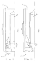
- Figure 4 is a side view of the apparatus 100 in which the gripper means 110 are situated at the head end p 1 of the section P at the time of detection of the presence of the section P itself.
- the handling method includes the step of:
- the motion stopping step d) includes the steps of:
- the step d 1 ) includes the steps of:
- Figure 5 is a side view of the apparatus 100 corresponding to the step d 1-1 ) of the method of the present invention, in which the gripper means 110 are situated at the terminal end p 2 of the section P at the time of determination of the absence of the section P itself.
- the step d 1 ) of providing a deactivation control signal s OFF to the first drive means 111a may include the steps of:
- Figure 6 is a side view of the apparatus 100 corresponding to the steps d 1-2 ) and d 1-3 ) of the method of the present invention, in which the speed of the gripper means 110 is decreased along the section l 3 of predetermined length.
- the step d 2 includes the step of:
- the step d 2-1 ) of moving the gripper means 10 to the support means includes the step of:
- the step d 3 ) includes the additional step of d 3-1 ) stopping the motion of the gripper means 110 in the vertical direction Z-Z at the terminal end p 2 of the section P and upon reception of the deactivation control signal s OFF .
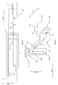
- Figure 7 is a side view of the apparatus 100 corresponding to the step d 3-1 ) of the method of the present invention, in which the gripper means 110 are stopped at the terminal end p 2 of the section P.
- the step d 4 ) includes the step of:
- the step d 5 ) includes the step of:
- the handling method includes the step of:
- Figure 8 is a side view of the apparatus 100 corresponding to the step e) of the method of the present invention, in which the gripper means 110 grasp the section P at its terminal end p 2 .
- the handling method includes the step of:
- step f) of moving the gripper means 110 includes the steps of:
- Figure 9 is a side view of the apparatus 100 and the section working unit 300 corresponding to the step f 2 ) of the method of the present invention, in which the gripper means 110 are situated at the working unit 300 for sections P.
- the gripper means 110 are situated at the first side f 1 of the apparatus 100.
- the method includes an initial step, in which the control means 150 operate the detection means 120 and the first drive means 111a, to move the gripper means 110 in the direction Y-Y from the first side f 1 to the second side f 2 of the apparatus 100. It shall be noted that the control means 140 generate a controlling signal s v to control the speed of the first drive means 111a. Particularly, the gripper means 110 are moved from the first side f 1 to the second side f 2 at a constant speed.
- the detection means 120 emit a light signal to determine the presence or absence of the section P on the support platform 107a.
- the control means 150 receive the detection signal s 0 representative of a first predetermined voltage range that determines the absence of the section P. Particularly, the light beam emitted by the detection means 120 along a section of length l 1 , does not impinge on the section P.
- the control means 150 receive the detection signal s 1 representative of a second predetermined voltage range that determines the presence of the section P and hence the detection of the head end p 1 of the section P.
- the light beam emitted by the detection means 120 along a section of length l 2 i.e. equal to the length of the section P, impinges on the section P.
- the control means 150 receive the detection signal s 0 representative of the first predetermined voltage range that determines again the absence of the section P and hence the detection of the terminal end p 2 of the section P. In this case, the light beam emitted by the detection means 120 does not impinge on the section P.
- control means 150 receive the detection signal s 0 upon reception of the signal s 1 , these control means 150 transmit the deactivation control signal s OFF to the first drive means 111a.
- the gripper means 110 are slowed down along a predetermined section l 3 in the direction Y-Y (see Figure 6 ).
- the gripper means 110 are stopped at the terminal end p 2 of the section P.
- control means 150 transmit an activation control signal s ON to the second drive means 111b.
- the clamping vice 112 is thus moved in the vertical direction Z-Z along a section of predetermined length l 4 .
- control means 150 transmit a deactivation control signal s OFF to the second drive means 111b.
- the clamping vice 112 is stopped substantially at the terminal end p 2 of the section P.
- control means 150 transmit an activation control signal s ON to the first drive means 111a.
- the clamping vice 112 is thus moved towards the terminal end p 2 of the section P along a section l 5 in the direction Y-Y, to the first side f 1 of the apparatus 100.
- the clamping vice 112 moves to the terminal end p 2 of the section P until the retainer means 115 abut against the terminal end p 2 of the section P.
- the retainer means 115 As the retainer means 115 abut against the terminal end p 2 of the section P, they generate and transmit an enable signal s r to the control means 150.
- the control means 150 Upon reception of the enable signal s r , the control means 150 transmit a deactivation control signal s OFF to the first drive means 111a to stop the motion of the gripper means 110 in the direction Y-Y. At the same time, the control means 150 transmit an activation signal s ON to the actuator means 113 to move the jaws 112a, 112b towards each other and hold the section P in the clamping vice 112.
- the control means 150 transmit an activation control signal s ON to the first drive means 111a to move the gripper means 110, and hence the section P, in the direction Y-Y from the second side f 2 to the first side f 1 of the apparatus 100 along a section of length l 6 .
- control means 150 transmit a deactivation control signal, s OFF , e.g. through additional retainer means in the section working unit 300, to the first drive means 111a to stop the motion of the gripper means 110 in the direction Y-Y.
- control means 150 transmit a deactivation signal s OFF to the actuator means 113 to move the jaws 112a, 112b away from each other, to disengage and release the section P into the section working unit 300.
- the apparatus for handling sections and the method of the present invention fulfill the needs and obviate the prior art drawbacks as set out in the introduction of this disclosure.
Landscapes
- Engineering & Computer Science (AREA)
- Mechanical Engineering (AREA)
- Manipulator (AREA)
- Feeding Of Workpieces (AREA)
- Electrical Discharge Machining, Electrochemical Machining, And Combined Machining (AREA)
Priority Applications (3)
| Application Number | Priority Date | Filing Date | Title |
|---|---|---|---|
| AT09425247T ATE553880T1 (de) | 2009-06-26 | 2009-06-26 | Verfahren und vorrichtung zur handhabung von zu bearbeitenden abschnitten |
| PL09425247T PL2266748T3 (pl) | 2009-06-26 | 2009-06-26 | Sposób i aparat do obsługiwania kształtowników, które mają być poddane obróbce |
| EP09425247A EP2266748B1 (en) | 2009-06-26 | 2009-06-26 | Method and apparatus for handling sections to be worked |
Applications Claiming Priority (1)
| Application Number | Priority Date | Filing Date | Title |
|---|---|---|---|
| EP09425247A EP2266748B1 (en) | 2009-06-26 | 2009-06-26 | Method and apparatus for handling sections to be worked |
Publications (2)
| Publication Number | Publication Date |
|---|---|
| EP2266748A1 EP2266748A1 (en) | 2010-12-29 |
| EP2266748B1 true EP2266748B1 (en) | 2012-04-18 |
Family
ID=41350499
Family Applications (1)
| Application Number | Title | Priority Date | Filing Date |
|---|---|---|---|
| EP09425247A Active EP2266748B1 (en) | 2009-06-26 | 2009-06-26 | Method and apparatus for handling sections to be worked |
Country Status (3)
| Country | Link |
|---|---|
| EP (1) | EP2266748B1 (pl) |
| AT (1) | ATE553880T1 (pl) |
| PL (1) | PL2266748T3 (pl) |
Families Citing this family (1)
| Publication number | Priority date | Publication date | Assignee | Title |
|---|---|---|---|---|
| CN110280994B (zh) * | 2019-07-18 | 2021-02-26 | 贾广鹏 | 一种发动机缸盖座圈快速上料装置 |
Family Cites Families (3)
| Publication number | Priority date | Publication date | Assignee | Title |
|---|---|---|---|---|
| DE3872254D1 (de) * | 1987-12-15 | 1992-07-23 | Karl Rumpler | Fertigungseinrichtung. |
| FR2689807A1 (fr) * | 1992-04-08 | 1993-10-15 | Lyon Flex Ets Marcel Prost Dam | Ligne d'usinage de pièces en bois. |
| DE102004037879B4 (de) * | 2003-08-14 | 2008-09-11 | Boehringer Werkzeugmaschinen Gmbh | Schiebegreifer |
-
2009
- 2009-06-26 PL PL09425247T patent/PL2266748T3/pl unknown
- 2009-06-26 AT AT09425247T patent/ATE553880T1/de active
- 2009-06-26 EP EP09425247A patent/EP2266748B1/en active Active
Also Published As
| Publication number | Publication date |
|---|---|
| PL2266748T3 (pl) | 2012-09-28 |
| EP2266748A1 (en) | 2010-12-29 |
| ATE553880T1 (de) | 2012-05-15 |
Similar Documents
| Publication | Publication Date | Title |
|---|---|---|
| US10589394B2 (en) | Method and arrangement of introducing boreholes into a surface of a workpiece mounted in a stationary manner using a boring tool attached to an articulated-arm robot | |
| CN104918755B (zh) | 用于将两个可运动的单元在相对位置中彼此定位的方法和机器系统 | |
| CN103950071B (zh) | 一种数控裁板锯后上料的上料方法 | |
| EP3908426B1 (en) | Work centre to process section bars, in particular made of aluminium, light alloys, pvc or the like | |
| JP6170137B2 (ja) | 曲げ工具の自動的操作方法および製造装置 | |
| EP3960660A1 (en) | Conveyance device | |
| WO2019136998A1 (zh) | 一种具有视觉系统的瓷砖桁架机械装置 | |
| US10365637B2 (en) | Workpiece carrier with a code element for a production unit | |
| CN109839075A (zh) | 一种机器人自动测量系统及测量方法 | |
| US8485343B2 (en) | Conveying system having endless drive medium and conveying method | |
| EP2266748A1 (en) | Apparatus for handling sections to be worked | |
| US11583908B2 (en) | Bending beam for a swivel bending machine | |
| US8915695B2 (en) | Conveying system having endless drive medium and method for delivering/receiving article therein | |
| CN114210586A (zh) | 一种微钻在线分检系统 | |
| CN113714341A (zh) | 智能检测角度补偿控制系统 | |
| US10951092B2 (en) | Transport system, carriage, positioning apparatus, processing system, and positioning method | |
| KR101444833B1 (ko) | 문형 이송기계의 레이저간섭계를 이용한 동기이송 오차 제어 장치 및 방법 | |
| CN218081641U (zh) | 一种机床上下料用单向叉车系统以及自动化生产线 | |
| CN216609078U (zh) | Z轴碰撞检测机构 | |
| EP0410321A2 (en) | Method and apparatus for the automatic measurement of diameters and lenghts of solids of revolution | |
| ITUB20154937A1 (it) | Dispositivo di lavorazione perfezionato e relativo metodo di funzionamento. | |
| IT201800011042A1 (it) | Procedimento e apparecchiatura per il rilevamento della posizione di oggetti su un nastro trasportatore | |
| JPH10166307A (ja) | 原木径測定装置、原木の芯出し装置及び芯出し供給装置 | |
| FI113087B (fi) | Laitteisto hyllystöhississä kuorman dimensioiden mittaamiseksi | |
| CN221479320U (zh) | 天车自动校准定位的装置和系统 |
Legal Events
| Date | Code | Title | Description |
|---|---|---|---|
| PUAI | Public reference made under article 153(3) epc to a published international application that has entered the european phase |
Free format text: ORIGINAL CODE: 0009012 |
|
| AK | Designated contracting states |
Kind code of ref document: A1 Designated state(s): AT BE BG CH CY CZ DE DK EE ES FI FR GB GR HR HU IE IS IT LI LT LU LV MC MK MT NL NO PL PT RO SE SI SK TR |
|
| AX | Request for extension of the european patent |
Extension state: AL BA RS |
|
| 17P | Request for examination filed |
Effective date: 20110427 |
|
| 17Q | First examination report despatched |
Effective date: 20110516 |
|
| GRAP | Despatch of communication of intention to grant a patent |
Free format text: ORIGINAL CODE: EPIDOSNIGR1 |
|
| RIC1 | Information provided on ipc code assigned before grant |
Ipc: B23Q 17/20 20060101ALI20111020BHEP Ipc: B23Q 7/04 20060101AFI20111020BHEP |
|
| RTI1 | Title (correction) |
Free format text: METHOD AND APPARATUS FOR HANDLING SECTIONS TO BE WORKED |
|
| GRAS | Grant fee paid |
Free format text: ORIGINAL CODE: EPIDOSNIGR3 |
|
| GRAA | (expected) grant |
Free format text: ORIGINAL CODE: 0009210 |
|
| AK | Designated contracting states |
Kind code of ref document: B1 Designated state(s): AT BE BG CH CY CZ DE DK EE ES FI FR GB GR HR HU IE IS IT LI LT LU LV MC MK MT NL NO PL PT RO SE SI SK TR |
|
| REG | Reference to a national code |
Ref country code: GB Ref legal event code: FG4D |
|
| REG | Reference to a national code |
Ref country code: CH Ref legal event code: EP |
|
| REG | Reference to a national code |
Ref country code: IE Ref legal event code: FG4D |
|
| REG | Reference to a national code |
Ref country code: AT Ref legal event code: REF Ref document number: 553880 Country of ref document: AT Kind code of ref document: T Effective date: 20120515 |
|
| REG | Reference to a national code |
Ref country code: DE Ref legal event code: R096 Ref document number: 602009006445 Country of ref document: DE Effective date: 20120614 |
|
| REG | Reference to a national code |
Ref country code: NL Ref legal event code: VDEP Effective date: 20120418 |
|
| REG | Reference to a national code |
Ref country code: AT Ref legal event code: MK05 Ref document number: 553880 Country of ref document: AT Kind code of ref document: T Effective date: 20120418 |
|
| LTIE | Lt: invalidation of european patent or patent extension |
Effective date: 20120418 |
|
| REG | Reference to a national code |
Ref country code: PL Ref legal event code: T3 |
|
| PG25 | Lapsed in a contracting state [announced via postgrant information from national office to epo] |
Ref country code: CY Free format text: LAPSE BECAUSE OF FAILURE TO SUBMIT A TRANSLATION OF THE DESCRIPTION OR TO PAY THE FEE WITHIN THE PRESCRIBED TIME-LIMIT Effective date: 20120418 Ref country code: FI Free format text: LAPSE BECAUSE OF FAILURE TO SUBMIT A TRANSLATION OF THE DESCRIPTION OR TO PAY THE FEE WITHIN THE PRESCRIBED TIME-LIMIT Effective date: 20120418 Ref country code: LT Free format text: LAPSE BECAUSE OF FAILURE TO SUBMIT A TRANSLATION OF THE DESCRIPTION OR TO PAY THE FEE WITHIN THE PRESCRIBED TIME-LIMIT Effective date: 20120418 Ref country code: IS Free format text: LAPSE BECAUSE OF FAILURE TO SUBMIT A TRANSLATION OF THE DESCRIPTION OR TO PAY THE FEE WITHIN THE PRESCRIBED TIME-LIMIT Effective date: 20120818 Ref country code: NO Free format text: LAPSE BECAUSE OF FAILURE TO SUBMIT A TRANSLATION OF THE DESCRIPTION OR TO PAY THE FEE WITHIN THE PRESCRIBED TIME-LIMIT Effective date: 20120718 Ref country code: SE Free format text: LAPSE BECAUSE OF FAILURE TO SUBMIT A TRANSLATION OF THE DESCRIPTION OR TO PAY THE FEE WITHIN THE PRESCRIBED TIME-LIMIT Effective date: 20120418 |
|
| PG25 | Lapsed in a contracting state [announced via postgrant information from national office to epo] |
Ref country code: SI Free format text: LAPSE BECAUSE OF FAILURE TO SUBMIT A TRANSLATION OF THE DESCRIPTION OR TO PAY THE FEE WITHIN THE PRESCRIBED TIME-LIMIT Effective date: 20120418 Ref country code: LV Free format text: LAPSE BECAUSE OF FAILURE TO SUBMIT A TRANSLATION OF THE DESCRIPTION OR TO PAY THE FEE WITHIN THE PRESCRIBED TIME-LIMIT Effective date: 20120418 Ref country code: PT Free format text: LAPSE BECAUSE OF FAILURE TO SUBMIT A TRANSLATION OF THE DESCRIPTION OR TO PAY THE FEE WITHIN THE PRESCRIBED TIME-LIMIT Effective date: 20120820 Ref country code: HR Free format text: LAPSE BECAUSE OF FAILURE TO SUBMIT A TRANSLATION OF THE DESCRIPTION OR TO PAY THE FEE WITHIN THE PRESCRIBED TIME-LIMIT Effective date: 20120418 Ref country code: GR Free format text: LAPSE BECAUSE OF FAILURE TO SUBMIT A TRANSLATION OF THE DESCRIPTION OR TO PAY THE FEE WITHIN THE PRESCRIBED TIME-LIMIT Effective date: 20120719 |
|
| PG25 | Lapsed in a contracting state [announced via postgrant information from national office to epo] |
Ref country code: BE Free format text: LAPSE BECAUSE OF FAILURE TO SUBMIT A TRANSLATION OF THE DESCRIPTION OR TO PAY THE FEE WITHIN THE PRESCRIBED TIME-LIMIT Effective date: 20120418 |
|
| PG25 | Lapsed in a contracting state [announced via postgrant information from national office to epo] |
Ref country code: MC Free format text: LAPSE BECAUSE OF NON-PAYMENT OF DUE FEES Effective date: 20120630 Ref country code: SK Free format text: LAPSE BECAUSE OF FAILURE TO SUBMIT A TRANSLATION OF THE DESCRIPTION OR TO PAY THE FEE WITHIN THE PRESCRIBED TIME-LIMIT Effective date: 20120418 Ref country code: NL Free format text: LAPSE BECAUSE OF FAILURE TO SUBMIT A TRANSLATION OF THE DESCRIPTION OR TO PAY THE FEE WITHIN THE PRESCRIBED TIME-LIMIT Effective date: 20120418 Ref country code: CZ Free format text: LAPSE BECAUSE OF FAILURE TO SUBMIT A TRANSLATION OF THE DESCRIPTION OR TO PAY THE FEE WITHIN THE PRESCRIBED TIME-LIMIT Effective date: 20120418 Ref country code: DK Free format text: LAPSE BECAUSE OF FAILURE TO SUBMIT A TRANSLATION OF THE DESCRIPTION OR TO PAY THE FEE WITHIN THE PRESCRIBED TIME-LIMIT Effective date: 20120418 Ref country code: AT Free format text: LAPSE BECAUSE OF FAILURE TO SUBMIT A TRANSLATION OF THE DESCRIPTION OR TO PAY THE FEE WITHIN THE PRESCRIBED TIME-LIMIT Effective date: 20120418 Ref country code: EE Free format text: LAPSE BECAUSE OF FAILURE TO SUBMIT A TRANSLATION OF THE DESCRIPTION OR TO PAY THE FEE WITHIN THE PRESCRIBED TIME-LIMIT Effective date: 20120418 Ref country code: RO Free format text: LAPSE BECAUSE OF FAILURE TO SUBMIT A TRANSLATION OF THE DESCRIPTION OR TO PAY THE FEE WITHIN THE PRESCRIBED TIME-LIMIT Effective date: 20120418 |
|
| PLBE | No opposition filed within time limit |
Free format text: ORIGINAL CODE: 0009261 |
|
| STAA | Information on the status of an ep patent application or granted ep patent |
Free format text: STATUS: NO OPPOSITION FILED WITHIN TIME LIMIT |
|
| PG25 | Lapsed in a contracting state [announced via postgrant information from national office to epo] |
Ref country code: MK Free format text: LAPSE BECAUSE OF FAILURE TO SUBMIT A TRANSLATION OF THE DESCRIPTION OR TO PAY THE FEE WITHIN THE PRESCRIBED TIME-LIMIT Effective date: 20120418 |
|
| 26N | No opposition filed |
Effective date: 20130121 |
|
| REG | Reference to a national code |
Ref country code: IE Ref legal event code: MM4A |
|
| PG25 | Lapsed in a contracting state [announced via postgrant information from national office to epo] |
Ref country code: IE Free format text: LAPSE BECAUSE OF NON-PAYMENT OF DUE FEES Effective date: 20120626 Ref country code: ES Free format text: LAPSE BECAUSE OF FAILURE TO SUBMIT A TRANSLATION OF THE DESCRIPTION OR TO PAY THE FEE WITHIN THE PRESCRIBED TIME-LIMIT Effective date: 20120729 |
|
| REG | Reference to a national code |
Ref country code: DE Ref legal event code: R097 Ref document number: 602009006445 Country of ref document: DE Effective date: 20130121 |
|
| PG25 | Lapsed in a contracting state [announced via postgrant information from national office to epo] |
Ref country code: BG Free format text: LAPSE BECAUSE OF FAILURE TO SUBMIT A TRANSLATION OF THE DESCRIPTION OR TO PAY THE FEE WITHIN THE PRESCRIBED TIME-LIMIT Effective date: 20120718 Ref country code: MT Free format text: LAPSE BECAUSE OF FAILURE TO SUBMIT A TRANSLATION OF THE DESCRIPTION OR TO PAY THE FEE WITHIN THE PRESCRIBED TIME-LIMIT Effective date: 20120418 |
|
| PGFP | Annual fee paid to national office [announced via postgrant information from national office to epo] |
Ref country code: PL Payment date: 20130612 Year of fee payment: 5 |
|
| REG | Reference to a national code |
Ref country code: CH Ref legal event code: PL |
|
| GBPC | Gb: european patent ceased through non-payment of renewal fee |
Effective date: 20130626 |
|
| PG25 | Lapsed in a contracting state [announced via postgrant information from national office to epo] |
Ref country code: LI Free format text: LAPSE BECAUSE OF NON-PAYMENT OF DUE FEES Effective date: 20130630 Ref country code: CH Free format text: LAPSE BECAUSE OF NON-PAYMENT OF DUE FEES Effective date: 20130630 Ref country code: GB Free format text: LAPSE BECAUSE OF NON-PAYMENT OF DUE FEES Effective date: 20130626 |
|
| PG25 | Lapsed in a contracting state [announced via postgrant information from national office to epo] |
Ref country code: LU Free format text: LAPSE BECAUSE OF NON-PAYMENT OF DUE FEES Effective date: 20120626 |
|
| PG25 | Lapsed in a contracting state [announced via postgrant information from national office to epo] |
Ref country code: HU Free format text: LAPSE BECAUSE OF FAILURE TO SUBMIT A TRANSLATION OF THE DESCRIPTION OR TO PAY THE FEE WITHIN THE PRESCRIBED TIME-LIMIT Effective date: 20090626 |
|
| PGFP | Annual fee paid to national office [announced via postgrant information from national office to epo] |
Ref country code: FR Payment date: 20140619 Year of fee payment: 6 |
|
| REG | Reference to a national code |
Ref country code: PL Ref legal event code: LAPE |
|
| REG | Reference to a national code |
Ref country code: DE Ref legal event code: R082 Ref document number: 602009006445 Country of ref document: DE Representative=s name: KADOR & PARTNER PARTG MBB, DE Ref country code: DE Ref legal event code: R082 Ref document number: 602009006445 Country of ref document: DE Representative=s name: KADOR & PARTNER, DE Ref country code: DE Ref legal event code: R081 Ref document number: 602009006445 Country of ref document: DE Owner name: MECAL S.R.L., IT Free format text: FORMER OWNER: ME.C.AL. S.P.A., FRASCAROLO, PAVIA, IT Ref country code: DE Ref legal event code: R082 Ref document number: 602009006445 Country of ref document: DE Representative=s name: KADOR & PARTNER PART MBB PATENTANWAELTE, DE Ref country code: DE Ref legal event code: R082 Ref document number: 602009006445 Country of ref document: DE Representative=s name: KADOR & PARTNER PARTG MBB PATENTANWAELTE, DE |
|
| PG25 | Lapsed in a contracting state [announced via postgrant information from national office to epo] |
Ref country code: PL Free format text: LAPSE BECAUSE OF NON-PAYMENT OF DUE FEES Effective date: 20140626 |
|
| REG | Reference to a national code |
Ref country code: FR Ref legal event code: ST Effective date: 20160229 |
|
| PG25 | Lapsed in a contracting state [announced via postgrant information from national office to epo] |
Ref country code: FR Free format text: LAPSE BECAUSE OF NON-PAYMENT OF DUE FEES Effective date: 20150630 |
|
| REG | Reference to a national code |
Ref country code: DE Ref legal event code: R082 Ref document number: 602009006445 Country of ref document: DE Representative=s name: KADOR & PARTNER PARTG MBB PATENTANWAELTE, DE Ref country code: DE Ref legal event code: R081 Ref document number: 602009006445 Country of ref document: DE Owner name: MECAL MACHINERY S.R.L., IT Free format text: FORMER OWNER: MECAL S.R.L., FRASCAROLO, IT |
|
| PGFP | Annual fee paid to national office [announced via postgrant information from national office to epo] |
Ref country code: IT Payment date: 20220610 Year of fee payment: 14 |
|
| P01 | Opt-out of the competence of the unified patent court (upc) registered |
Effective date: 20230602 |
|
| P02 | Opt-out of the competence of the unified patent court (upc) changed |
Effective date: 20230821 |
|
| PG25 | Lapsed in a contracting state [announced via postgrant information from national office to epo] |
Ref country code: IT Free format text: LAPSE BECAUSE OF NON-PAYMENT OF DUE FEES Effective date: 20230626 |
|
| PGFP | Annual fee paid to national office [announced via postgrant information from national office to epo] |
Ref country code: DE Payment date: 20250618 Year of fee payment: 17 |
|
| PGFP | Annual fee paid to national office [announced via postgrant information from national office to epo] |
Ref country code: TR Payment date: 20250617 Year of fee payment: 17 |