EP2266437B1 - Opening device for an extending guide and extending guide - Google Patents
Opening device for an extending guide and extending guide Download PDFInfo
- Publication number
- EP2266437B1 EP2266437B1 EP10166316.9A EP10166316A EP2266437B1 EP 2266437 B1 EP2266437 B1 EP 2266437B1 EP 10166316 A EP10166316 A EP 10166316A EP 2266437 B1 EP2266437 B1 EP 2266437B1
- Authority
- EP
- European Patent Office
- Prior art keywords
- housing
- guide
- energy storage
- storage unit
- pull
- Prior art date
- Legal status (The legal status is an assumption and is not a legal conclusion. Google has not performed a legal analysis and makes no representation as to the accuracy of the status listed.)
- Active
Links
- 238000004146 energy storage Methods 0.000 claims description 14
- 239000012190 activator Substances 0.000 claims description 9
- 238000006073 displacement reaction Methods 0.000 claims description 4
- 230000006835 compression Effects 0.000 description 8
- 238000007906 compression Methods 0.000 description 8
- 241000538562 Banjos Species 0.000 description 1
- 238000010521 absorption reaction Methods 0.000 description 1
- 230000000694 effects Effects 0.000 description 1
- 238000003780 insertion Methods 0.000 description 1
- 230000037431 insertion Effects 0.000 description 1
- 239000000463 material Substances 0.000 description 1
- 230000003014 reinforcing effect Effects 0.000 description 1
- 230000002040 relaxant effect Effects 0.000 description 1
- 239000007787 solid Substances 0.000 description 1
- 239000006228 supernatant Substances 0.000 description 1
Images


Classifications
-
- A—HUMAN NECESSITIES
- A47—FURNITURE; DOMESTIC ARTICLES OR APPLIANCES; COFFEE MILLS; SPICE MILLS; SUCTION CLEANERS IN GENERAL
- A47B—TABLES; DESKS; OFFICE FURNITURE; CABINETS; DRAWERS; GENERAL DETAILS OF FURNITURE
- A47B88/00—Drawers for tables, cabinets or like furniture; Guides for drawers
- A47B88/40—Sliding drawers; Slides or guides therefor
- A47B88/453—Actuated drawers
- A47B88/46—Actuated drawers operated by mechanically-stored energy, e.g. by springs
- A47B88/463—Actuated drawers operated by mechanically-stored energy, e.g. by springs self-opening
Definitions
- the present invention relates to an opening device of a pull-out guide, in particular for drawers according to the preamble of claim 1 and a pull-out guide.
- a disadvantage of these known opening devices is that when high pulses occur, for example, by strong abutment of the drawer in the closing direction, the components of the locking mechanism are very heavily stressed. Particularly heavy is the load when due to heavy drawer loading and high recoil impulses occur due to a powerful impact of the drawer in the closing direction. All loads must be from the rigidly mounted components of the locking mechanism, in particular the housing, a control cam arranged therein and a control element coupled to the detent pawl, which can be moved along the control cam and by which the detent pawl can be fixed against the force of the energy accumulator in a closed position of the pull-out guide.
- the object of the present invention is therefore to provide an opening device of a pull-out guide, which can withstand occurring high pulses, without forming the components of the latching mechanism reinforced material.
- the control cam of the latching mechanism is spring-loaded in the housing of the latching mechanism.
- the control cam of the latching mechanism is spring-loaded in the housing of the latching mechanism.
- control cam is integrally formed on another housing of the latching mechanism in the displacement direction of the pull-out guide member.
- a second force accumulator is fixed in the housing of the latching mechanism, which holds the component in an end position pushed onto the housing, wherein the force exerted on the component by the second energy accumulator is stronger than that of the first accumulator force exerted on the component in the closed position of the pull-out guide.
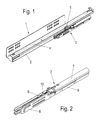
- a design variant of a pull-out guide according to the invention with an opening device arranged thereon is shown overall, which is used for furniture parts movably arranged on a furniture carcass, in particular drawers and the like.
- the pull-out 1 consists of a fixed to a furniture body guide rail 2, to which the opening device 3 is fixed and a movable rail 2 on the guide rail 4, to which an activator 5 is fixed, with which the opening device 3 during a closing or opening operation of movable furniture part is activated.
- the pull-out guide 1 with the opening device 3 arranged thereon serves for the storage of drawers, but can also be used for other displaceable elements such as slide holders, shelves or the like.
- an aussvernostirnde center rail can be arranged in the pullout guide between the guide rail 2 and the running rail 4 an aussvernostirnde center rail.
- Opening device 3 shown in detail has a guide housing 6, which on the guide rail 2, as in Fig. 1 is shown attached.
- a guide 14 is formed in the form of a backdrop-shaped recess.
- a latch 8 is guided displaceably.
- the detent pawl 8 has a receptacle 19 for the activator 5 attached to the movable running rail 4.
- the opening device 3 further comprises a housing 7 with a latching mechanism to fix the latch 8 in two spaced-apart positions.
- the latch 8 In a first opening position, the latch 8 is retracted and retracted by retracting the latch 8 in a remote from the housing 7 end of the guide 14, the remote from the housing 7 end of the guide 14 is L-shaped, so that the latch 8 when retracting into the short L-piece of the guide 14 transversely to the direction of movement of the running rail 4 and thus transversely to the direction of movement of the activator 5 tilts and thereby releases the activator 5.
- the running rail 4 can be moved further into its opening end position.
- the second fixed position of the detent pawl 8 is the closed position in which the detent pawl 8 locks against the force of an energy accumulator 12.
- the latch 8 is coupled via a rod 11 with the energy storage device 12 and a control element 13 with the latching mechanism in the housing 7.
- the locking mechanism points, in particular in Fig. 4 can be seen, in addition to the housing 7 and fixed in the housing 7 with one end of energy storage 12, which is preferably designed as a compression spring, coupled to the latch 8 control element 13 which is movable along a control cam 15 and through which the latch 8 can be fixed in a closed position of the pull-out guide 1 against the force of the energy accumulator 12.
- energy storage 12 which is preferably designed as a compression spring
- the control cam 15 is preferably integrally formed on a component 9 which is displaceably arranged on the housing 7 in the displacement direction of the pull-out guide 1.
- a component 9 which is displaceably arranged on the housing 7 in the displacement direction of the pull-out guide 1.
- webs with recesses 20, 21 are preferably integrally formed on the housing 7, which is preferably cylindrical, in the laterally formed on the component 9 lugs 22 and a supernatant 23 are inserted, so that the component 9 is parallel to the displacement direction of the rod 11 slidably fixed to the housing 7.
- a second force accumulator 10 is fixed to the housing 7, which holds the component 9 in a pushed onto the housing 7 end position.
- the second energy accumulator 14 is preferably designed as a compression or tension spring, depending on whether the energy accumulator 10 is fixed to a remote from the guide housing 6 or the guide housing 6 near the end of the housing 7.
- the second force accumulator is designed as a tension spring, which is fixed to a remote from the guide housing 6 end of the housing 7 and at one end facing the guide housing 6 has a hook which engages in an integrally formed on the part 9 eyelet 16 and so keeps the component in the pushed onto the housing 7 end position.
- An embodiment of the force accumulator 10 as a solid rubber part is also conceivable.
- the latch 8 is disengaged from the activator 5.
- the movable furniture part In this position, the movable furniture part is in the open position.
- the activator 5 first couples again to the latching pawl 8 and thus moves the latching pawl 8 in the direction of the housing 7 of the latching mechanism.
- the compression spring 12 via the rod 11 which rests with one end 17 in the compression spring 12 and a ring piece 18 whose diameter is larger than the diameter of the compression spring 12, pressed against the compression spring, and is biased for the next ejection operation ,
- the control 13 is moved within the control cam 15.
- An intermediate position on the way to the fully retracted position of the movable furniture part is in FIG. 5B shown.
- Fig. 5c shows the position of the control 13, wherein the movable furniture part is retracted to the stop in the furniture body.
- the detent pawl 8 is then moved a short distance back in the opening direction, whereby the control element 13 in one of the Closed position corresponding to the movable furniture part kink in the control cam 15 and is held there.
- the second force accumulator 10 designed here as a tension spring, as in FIG Fig. 5e shown, deflected and absorbs this impulse.
- the spring constant of the second energy accumulator 10 is designed to be stronger than the spring force of the first energy accumulator 12, so that the second energy accumulator 10, as in Fig. 5f shown, the component 9 with the control cam 15 after deflection again back to the starting position of the component 9 on the housing 7 against the spring force of the first energy accumulator 12 retracts.
Description
Die vorliegende Erfindung betrifft eine Öffnungsvorrichtung einer Ausziehführung, insbesondere für Schubkästen gemäß dem Oberbegriff des Anspruchs 1 sowie eine Ausziehführung.The present invention relates to an opening device of a pull-out guide, in particular for drawers according to the preamble of claim 1 and a pull-out guide.
Gattungsgemäße Öffnungsvorrichtungen für Ausziehführungen sind in zahlreichen Ausführungen aus dem Stand der Technik bekannt, wie zum Beispiel aus dem
Nachteilig bei diesen bekannten Öffnungsvorrichtungen ist, dass bei auftretenden hohen Impulsen, beispielsweise durch starkes Anstoßen des Schubkastens in Schließrichtung, die Bauteile des Rastmechanismus sehr stark beansprucht werden. Besonders stark ist die Belastung, wenn aufgrund schwerer Schubkastenbeladung auch hohe Rückstoßimpulse aufgrund eines kraftvollen Anstoßes des Schubkastens in Schließrichtung auftreten. Sämtliche Belastungen müssen von den starr gelagerten Bauteilen des Rastmechanismus, insbesondere dem Gehäuse, einer darin angeordneten Steuerkurve und einem mit der Rastklinke gekoppelten Steuerelement, das entlang der Steuerkurve verfahrbar und durch das die Rastklinke in einer Schließposition der Ausziehführung gegen die Kraft des Kraftspeichers fixierbar ist, aufgenommen werden.A disadvantage of these known opening devices is that when high pulses occur, for example, by strong abutment of the drawer in the closing direction, the components of the locking mechanism are very heavily stressed. Particularly heavy is the load when due to heavy drawer loading and high recoil impulses occur due to a powerful impact of the drawer in the closing direction. All loads must be from the rigidly mounted components of the locking mechanism, in particular the housing, a control cam arranged therein and a control element coupled to the detent pawl, which can be moved along the control cam and by which the detent pawl can be fixed against the force of the energy accumulator in a closed position of the pull-out guide.
Zur Lösung dieses Problems wurde bisher die Dimensionierung der Bauteile so ausgelegt, dass diese den auftretenden hohen Impulsen Stand halten können. Dies führt allerdings zu Bauraumeinschränkungen im gesamten System.To solve this problem, the dimensioning of the components has so far been designed so that they can withstand the high pulses that occur. However, this leads to space limitations throughout the system.
Aufgabe der vorliegenden Erfindung ist es daher, eine Öffnungsvorrichtung einer Ausziehführung bereit zu stellen, die auftretenden hohen Impulsen Stand halten kann, ohne die Bauteile des Rastmechanismus materialverstärkt auszubilden.The object of the present invention is therefore to provide an opening device of a pull-out guide, which can withstand occurring high pulses, without forming the components of the latching mechanism reinforced material.
Diese Aufgabe wird durch eine Öffnungsvorrichtung einer Ausziehführung mit den Merkmalen des Anspruchs 1 sowie durch eine Ausziehführung mit den Merkmalen des Anspruchs 8 gelöst.This object is achieved by an opening device of a pull-out with the features of claim 1 and by a pull-out with the features of
Erfindungsgemäß ist die Steuerkurve des Rastmechanismus federbelastet in dem Gehäuse des Rastmechanismus festgelegt. Beim schnellen Einschieben eines Schubkastens in den Möbelkorpus wird der in dem Gehäuse des Rastmechanismus festgelegte Kraftspeicher so stark belastet, dass er das Steuerelement mit großer Kraft in die Steuerkurve drückt. Durch die Federbelastung der Steuerkurve kann diese dem Druck des Steuerelements in einem vorbestimmten Maß nachgeben und anschließend wieder in die Ausgangsposition zurückfedern. Dadurch werden die im normalen Gebrauch auftretenden Impulsspitzen wirkungsvoll aufgenommen und vernichtet, und die betroffenen Bauteile somit spürbar entlastet.According to the invention, the control cam of the latching mechanism is spring-loaded in the housing of the latching mechanism. During rapid insertion of a drawer in the furniture body of the fixed in the housing of the locking mechanism memory is charged so much that he presses the control with great force in the control curve. By the spring load of the control cam, this can yield to the pressure of the control to a predetermined degree and then spring back to the starting position. As a result, the pulse peaks occurring in normal use are effectively absorbed and destroyed, thus noticeably relieving the affected components.
Gemäß einer Ausführungsvariante der Erfindung ist die Steuerkurve an einem anderen Gehäuse des Rastmechanismus in Verschieberichtung der Ausziehführung verschiebbar angeordneten Bauteil angeformt. Dadurch kann die Bewegungsrichtung der Steuerkurve beim Abfedern der lmpulsspitze in einfacher Weise gesteuert werden.According to one embodiment of the invention, the control cam is integrally formed on another housing of the latching mechanism in the displacement direction of the pull-out guide member. As a result, the direction of movement of the control cam can be controlled in a simple manner during the absorption of the impulse tip.
Gemäß einer weiteren Ausführungsvariante ist in dem Gehäuse des Rastmechanismus ein zweiter Kraftspeicher festgelegt, der das Bauteil in einer auf das Gehäuse aufgeschobenen Endstellung hält, wobei die von dem zweiten Kraftspeicher auf das Bauteil ausgeübte Kraft stärker ist als die von dem ersten Kraftspeicher in der Schließposition der Ausziehführung auf das Bauteil ausgeübte Kraft. Dadurch werden Impulsspitzen wirkungsvoll abgefedert, ohne die Wirkung des ersten Kraftspeichers beim Ausstoßen des Schubkastens zu beeinträchtigen.According to a further embodiment, a second force accumulator is fixed in the housing of the latching mechanism, which holds the component in an end position pushed onto the housing, wherein the force exerted on the component by the second energy accumulator is stronger than that of the first accumulator force exerted on the component in the closed position of the pull-out guide. As a result, pulse peaks are effectively cushioned without affecting the effect of the first energy accumulator when ejecting the drawer.
Nachfolgend wird ein Ausführungsbeispiel der Erfindung anhand der beiliegenden Zeichnungen näher erläutert. Es zeigen:
- Fig. 1
- eine schematische perspektivische Darstellung einer Ausführungsform einer erfindungsgemäßen Ausziehführung,
- Fig. 2
- eine schematische perspektivische Darstellung einer Ausführungsform einer an der Ausziehführung angeordneten Öffnungsvorrichtung,
- Fig. 3 a bis d
- unterschiedliche Draufsichten auf die Öffnungsvorrichtung aus
Fig. 2 , - Fig.4
- eine schematische perspektivische Explosionsdarstellung der Öffnungsvorrichtung aus
Fig. 2 und - Fig. 5 a bis h
- eine schematische Darstellung des Bewegungsablaufes bei einem Vorspannen bzw. Entspannen der Öffnungsvorrichtung.
- Fig. 1
- a schematic perspective view of an embodiment of a pull-out guide according to the invention,
- Fig. 2
- a schematic perspective view of an embodiment of an arranged on the pull-out opening device,
- Fig. 3 a to d
- different plan views of the opening device
Fig. 2 . - Figure 4
- a schematic perspective exploded view of the opening device
Fig. 2 and - Fig. 5 a to h
- a schematic representation of the movement sequence in a biasing or relaxing the opening device.
In
Die in den
Die Öffnungsvorrichtung 3 weist des Weiteren ein Gehäuse 7 mit einem Rastmechanismus auf, um die Rastklinke 8 in zwei voneinander beabstandeten Positionen zu fixieren. In einer ersten Öffnungsposition ist die Rastklinke 8 durch Einfahren der Rastklinke 8 in einem von dem Gehäuse 7 entfernten Ende der Führung 14 eingefahren und verrastet, wobei das von dem Gehäuse 7 entfernte Ende der Führung 14 L-förmig geformt ist, so dass die Rastklinke 8 beim Einfahren in das kurze L-Stück der Führung 14 quer zur Bewegungsrichtung der Laufschiene 4 und somit quer zur Bewegungsrichtung des Aktivators 5 wegkippt und dadurch den Aktivator 5 freigibt. Dadurch kann die Laufschiene 4 weiter in ihre Offnungsendstellung verschoben werden.The
Die zweite fixierte Position der Rastklinke 8 ist die Schließposition, bei der die Rastklinke 8 gegen die Kraft eines Kraftspeichers 12 verrastet. Die Rastklinke 8 ist dabei über eine Stange 11 mit dem Kraftspeicher 12 und über ein Steuerelement 13 mit dem Rastmechanismus in dem Gehäuse 7 gekoppelt.The second fixed position of the
Der Rastmechanismus weist, wie insbesondere in
Die Steuerkurve 15 ist dabei bevorzugt an einem an dem Gehäuse 7 in Verschieberichtung der Ausziehführung 1 verschiebbar angeordneten Bauteil 9 angeformt. Dazu sind vorzugsweise an dem Gehäuse 7, das bevorzugt zylinderförmig ausgebildet ist, Stege mit Ausnehmungen 20, 21 angeformt, in die seitlich an dem Bauteil 9 angeformte Nasen 22 bzw. ein Überstand 23 einschiebbar sind, so dass das Bauteil 9 parallel zur Verschieberichtung der Stange 11 verschiebbar an dem Gehäuse 7 festlegbar ist.The
Des Weiteren ist an dem Gehäuse 7 ein zweiter Kraftspeicher 10 festgelegt, der das Bauteil 9 in einer auf das Gehäuse 7 aufgeschobenen Endstellung hält. Der zweite Kraftspeicher 14 ist dabei bevorzugt als Druck- oder Zugfeder ausgebildet, je nachdem ob der Kraftspeicher 10 an einem von dem Führungsgehäuse 6 entfernten oder einem dem Führungsgehäuse 6 nahen Ende des Gehäuses 7 festgelegt ist. In der hier gezeigten Ausführungsvariante ist der zweite Kraftspeicher als Zugfeder ausgebildet, die an einem von dem Führungsgehäuse 6 entfernten Ende des Gehäuses 7 festgelegt ist und an einem dem Führungsgehäuse 6 zugewandten Ende einen Haken aufweist, der in eine an dem Bauteil 9 angeformten Öse 16 eingreift und so das Bauteil in der auf das Gehäuse 7 aufgeschobenen Endstellung hält. Eine Ausbildung des Kraftspeichers 10 als massives Gummiteil ist ebenfalls denkbar.Furthermore, a
Die Funktionsweise des Rastmechanismus wird nachfolgend mit Bezug auf die
In der in
Wird das bewegliche Möbelteil mit großer Wucht in den Möbelkorpus eingefahren, so geht dies mit einer übermäßigen Komprimierung der Druckfeder 12 einher, so dass diese infolgedessen nach Erreichen der maximalen Schließposition mit großer Kraft die Rastklinke 8 in Öffnungsrichtung drückt und dabei das Steuerelement 13 verstärkt gegen die Steuerkurve 15 drückt. Dadurch wird der hier als Zugfeder ausgebildete zweite Kraftspeicher 10, wie in
Soll das bewegliche Möbelteil anschließend wieder aus dem Möbelkorpus ausgefahren werden, so wird durch Drücken des beweglichen Möbelteils in Richtung des Möbelkorpus das Steuerelement 13 in die in
- 11
- Ausziehführungpull-out
- 22
- Führungsschieneguide rail
- 33
- Öffnungsvorrichtungopening device
- 44
- Laufschienerunner
- 55
- Aktivatoractivator
- 66
- Führungsgehäuseguide housing
- 77
- Gehäusecasing
- 88th
- Rastklinkelatch
- 99
- Bauteilcomponent
- 1010
- Kraftspeicherpower storage
- 1111
- Stangepole
- 1212
- Kraftspeicherpower storage
- 1313
- Steuerelementcontrol
- 1414
- Führungguide
- 1515
- Steuerkurvecam
- 1616
- Öseeyelet
- 1717
- EndeThe End
- 1818
- Ringstückbanjo
- 1919
- Aufnahmeadmission
- 2020
- Ausnehmungrecess
- 2121
- Ausnehmungrecess
- 2222
- Nasenose
- 2323
- ÜberstandGot over
Claims (8)
- An opening apparatus of a pull-out guide (1), especially for drawers, comprisinga) a guide housing (6),b) a detent (8) which is displaceable along a guide (14) integrally attached to the guide housing (6),c) wherein the detent (8) comprises a receptacle (19) for an activator (9) which can be coupled to a movable rail (4) of the pull-out guide (1),d) a latching mechanism with a housing (7), an energy storage unit (12) fixed to the housing, a radial cam (15), and a control element (13) coupled to the detent (8), which control element is movable along the radial cam (15) and can be fixed by the detent (8) in a closing position of the pull-out guide (1) against the force of the energy storage unit (12),
characterized in thate) the radial cam (15) is fixed in a spring-loaded manner to the housing (7). - An opening apparatus according to claim 1, characterized in that the radial cam (15) is integrally attached to a component (9) which is displaceably arranged on the housing (7) in the direction of displacement of the pull-out guide (1).
- An opening apparatus according to one of the claims 1 or 2, characterized in that the energy storage unit (12) is arranged as a pressure spring which acts on the detent (8) via a rod (11) arranged in the housing (7).
- An opening apparatus according to claim 2 or 3, characterized in that a second energy storage unit (10) is fixed to the housing (7), which energy storage unit holds the component (9) in an end position pushed up to the housing (7), wherein the force exerted by the second energy storage unit (10) on the component (9) is stronger than the force exerted by the first energy storage unit (12) on the component (9) in the closing position of the pull-out guide (1).
- An opening apparatus according to claim 4, characterized in that the second energy storage unit (10) is arranged as a tension spring fixed to an end of the housing (7) facing away from the detent (8).
- An opening apparatus according to claim 4, characterized in that the second energy storage unit (10) is arranged as a pressure spring fixed to an end of the housing (7) facing towards the detent (8).
- An opening apparatus according to claim 4, characterized in that the second energy storage unit (10) is arranged as a massive elastic part, especially a rubber part.
- A pull-out guide (1), comprising a guide rail (2) which can be fixed to a furniture body and on which a running rail (4) is guided directly or via a middle rail, characterized in that an opening apparatus according to one of the preceding claims is mounted on the guide rail (2).
Applications Claiming Priority (1)
| Application Number | Priority Date | Filing Date | Title |
|---|---|---|---|
| DE202009004957U DE202009004957U1 (en) | 2009-06-26 | 2009-06-26 | Opening device of a pull-out guide and pull-out guide |
Publications (2)
| Publication Number | Publication Date |
|---|---|
| EP2266437A1 EP2266437A1 (en) | 2010-12-29 |
| EP2266437B1 true EP2266437B1 (en) | 2014-12-24 |
Family
ID=42669799
Family Applications (1)
| Application Number | Title | Priority Date | Filing Date |
|---|---|---|---|
| EP10166316.9A Active EP2266437B1 (en) | 2009-06-26 | 2010-06-17 | Opening device for an extending guide and extending guide |
Country Status (3)
| Country | Link |
|---|---|
| EP (1) | EP2266437B1 (en) |
| DE (1) | DE202009004957U1 (en) |
| ES (1) | ES2533369T3 (en) |
Cited By (1)
| Publication number | Priority date | Publication date | Assignee | Title |
|---|---|---|---|---|
| WO2020259976A1 (en) | 2019-06-28 | 2020-12-30 | Paul Hettich Gmbh & Co. Kg | Ejection device for a movable furniture part |
Families Citing this family (2)
| Publication number | Priority date | Publication date | Assignee | Title |
|---|---|---|---|---|
| CN103783852B (en) * | 2014-01-24 | 2016-01-13 | 无锡晶美精密滑轨有限公司 | Self locking type slide rail |
| DE102018114169A1 (en) * | 2018-06-13 | 2019-12-19 | Wolfgang Held | Device for opening and closing stored covers |
Family Cites Families (5)
| Publication number | Priority date | Publication date | Assignee | Title |
|---|---|---|---|---|
| DE19935120C2 (en) * | 1999-07-27 | 2001-05-17 | Bulthaup Gmbh & Co | Device for opening and closing a drawer |
| DE202004019738U1 (en) * | 2004-12-17 | 2005-03-17 | Alfit Ag Goetzis | Drawer mounting incorporates latch on outer rail cooperating with fitting on other rail to hold it when drawn out, catch being released by touch-latch mechanism comprising rod whose lower end moves over heart-shaped cam |
| DE202005006945U1 (en) * | 2005-04-28 | 2006-05-04 | Grass Gmbh | Opening and closing system, especially for furniture parts |
| ATE420576T1 (en) * | 2006-11-24 | 2009-01-15 | Araquistain Basurto Donato Vic | DEVICE FOR OPENING AND CLOSING DOORS AND DRAWERS |
| DE202008013230U1 (en) * | 2008-10-08 | 2010-02-25 | Paul Hettich Gmbh & Co. Kg | Opening device for a pull-out guide |
-
2009
- 2009-06-26 DE DE202009004957U patent/DE202009004957U1/en not_active Expired - Lifetime
-
2010
- 2010-06-17 ES ES10166316.9T patent/ES2533369T3/en active Active
- 2010-06-17 EP EP10166316.9A patent/EP2266437B1/en active Active
Cited By (2)
| Publication number | Priority date | Publication date | Assignee | Title |
|---|---|---|---|---|
| WO2020259976A1 (en) | 2019-06-28 | 2020-12-30 | Paul Hettich Gmbh & Co. Kg | Ejection device for a movable furniture part |
| DE102019117593A1 (en) * | 2019-06-28 | 2020-12-31 | Paul Hettich Gmbh & Co. Kg | Ejection device for a movable furniture part |
Also Published As
| Publication number | Publication date |
|---|---|
| ES2533369T3 (en) | 2015-04-09 |
| DE202009004957U1 (en) | 2010-11-25 |
| EP2266437A1 (en) | 2010-12-29 |
Similar Documents
| Publication | Publication Date | Title |
|---|---|---|
| DE60124133T2 (en) | IMPROVING A LANZET EQUIPMENT TO POINTS THE SKIN | |
| EP1991750B1 (en) | Magnetic locking device | |
| EP2983559B1 (en) | Drive device for a movable furniture part | |
| EP2279680B1 (en) | Opening and closing device | |
| EP2272400B1 (en) | Locking device and drawer slide | |
| EP1912766B1 (en) | Electric device, in particular an electric hand tool | |
| WO2006058351A1 (en) | Drive device for a displaceably mounted furniture part | |
| EP2797460A1 (en) | Drive device for a movable furniture component | |
| WO2003079855A1 (en) | Self-closing drawer runners with integrated damping | |
| EP2266435B1 (en) | Opening and closing device for an extending guide and extending guide | |
| EP3439505B1 (en) | Furniture drive | |
| EP1557113B1 (en) | Closing device particularly for furniture drawers | |
| EP2654507A1 (en) | Opening and closing device for movable furniture parts | |
| WO2014082106A1 (en) | Device for moving a movable furniture part | |
| EP2266437B1 (en) | Opening device for an extending guide and extending guide | |
| EP3145366B1 (en) | Furniture drive | |
| EP3448204B1 (en) | Ejection device for a moveable furniture part and piece of furniture | |
| DE202013005797U1 (en) | Feeding device, pull-out guide with a collection device and furniture with a pull-out guide | |
| EP3518707B1 (en) | Retraction device for a drawer pullout | |
| DE20318929U1 (en) | Automatic retraction mechanism, for a furniture sliding drawer, has a structured head at the end of the piston rod as a connecting link with a holder at the sprung pawl without an additional damper spring | |
| AT8164U1 (en) | FEEDER AUTOMATICS FOR DRAWER EXTRACTION GUIDES | |
| DE202018100241U1 (en) | Ejector for a folding door or folding-sliding door | |
| EP2587964B1 (en) | Mechanically damped catch | |
| EP2630320B1 (en) | Drawer fitting for connecting a drawer to a central locking device | |
| EP3955773B1 (en) | Retraction device for a movable part |
Legal Events
| Date | Code | Title | Description |
|---|---|---|---|
| PUAI | Public reference made under article 153(3) epc to a published international application that has entered the european phase |
Free format text: ORIGINAL CODE: 0009012 |
|
| AK | Designated contracting states |
Kind code of ref document: A1 Designated state(s): AL AT BE BG CH CY CZ DE DK EE ES FI FR GB GR HR HU IE IS IT LI LT LU LV MC MK MT NL NO PL PT RO SE SI SK SM TR |
|
| AX | Request for extension of the european patent |
Extension state: BA ME RS |
|
| 17P | Request for examination filed |
Effective date: 20110201 |
|
| GRAJ | Information related to disapproval of communication of intention to grant by the applicant or resumption of examination proceedings by the epo deleted |
Free format text: ORIGINAL CODE: EPIDOSDIGR1 |
|
| GRAP | Despatch of communication of intention to grant a patent |
Free format text: ORIGINAL CODE: EPIDOSNIGR1 |
|
| INTG | Intention to grant announced |
Effective date: 20140915 |
|
| GRAS | Grant fee paid |
Free format text: ORIGINAL CODE: EPIDOSNIGR3 |
|
| GRAA | (expected) grant |
Free format text: ORIGINAL CODE: 0009210 |
|
| AK | Designated contracting states |
Kind code of ref document: B1 Designated state(s): AL AT BE BG CH CY CZ DE DK EE ES FI FR GB GR HR HU IE IS IT LI LT LU LV MC MK MT NL NO PL PT RO SE SI SK SM TR |
|
| REG | Reference to a national code |
Ref country code: GB Ref legal event code: FG4D Free format text: NOT ENGLISH |
|
| REG | Reference to a national code |
Ref country code: CH Ref legal event code: EP |
|
| REG | Reference to a national code |
Ref country code: IE Ref legal event code: FG4D Free format text: LANGUAGE OF EP DOCUMENT: GERMAN |
|
| REG | Reference to a national code |
Ref country code: AT Ref legal event code: REF Ref document number: 702670 Country of ref document: AT Kind code of ref document: T Effective date: 20150115 |
|
| REG | Reference to a national code |
Ref country code: DE Ref legal event code: R096 Ref document number: 502010008554 Country of ref document: DE Effective date: 20150212 |
|
| REG | Reference to a national code |
Ref country code: ES Ref legal event code: FG2A Ref document number: 2533369 Country of ref document: ES Kind code of ref document: T3 Effective date: 20150409 |
|
| REG | Reference to a national code |
Ref country code: NL Ref legal event code: VDEP Effective date: 20141224 |
|
| PG25 | Lapsed in a contracting state [announced via postgrant information from national office to epo] |
Ref country code: NO Free format text: LAPSE BECAUSE OF FAILURE TO SUBMIT A TRANSLATION OF THE DESCRIPTION OR TO PAY THE FEE WITHIN THE PRESCRIBED TIME-LIMIT Effective date: 20150324 Ref country code: FI Free format text: LAPSE BECAUSE OF FAILURE TO SUBMIT A TRANSLATION OF THE DESCRIPTION OR TO PAY THE FEE WITHIN THE PRESCRIBED TIME-LIMIT Effective date: 20141224 Ref country code: LT Free format text: LAPSE BECAUSE OF FAILURE TO SUBMIT A TRANSLATION OF THE DESCRIPTION OR TO PAY THE FEE WITHIN THE PRESCRIBED TIME-LIMIT Effective date: 20141224 |
|
| REG | Reference to a national code |
Ref country code: LT Ref legal event code: MG4D |
|
| PG25 | Lapsed in a contracting state [announced via postgrant information from national office to epo] |
Ref country code: GR Free format text: LAPSE BECAUSE OF FAILURE TO SUBMIT A TRANSLATION OF THE DESCRIPTION OR TO PAY THE FEE WITHIN THE PRESCRIBED TIME-LIMIT Effective date: 20150325 Ref country code: SE Free format text: LAPSE BECAUSE OF FAILURE TO SUBMIT A TRANSLATION OF THE DESCRIPTION OR TO PAY THE FEE WITHIN THE PRESCRIBED TIME-LIMIT Effective date: 20141224 Ref country code: HR Free format text: LAPSE BECAUSE OF FAILURE TO SUBMIT A TRANSLATION OF THE DESCRIPTION OR TO PAY THE FEE WITHIN THE PRESCRIBED TIME-LIMIT Effective date: 20141224 Ref country code: LV Free format text: LAPSE BECAUSE OF FAILURE TO SUBMIT A TRANSLATION OF THE DESCRIPTION OR TO PAY THE FEE WITHIN THE PRESCRIBED TIME-LIMIT Effective date: 20141224 |
|
| PG25 | Lapsed in a contracting state [announced via postgrant information from national office to epo] |
Ref country code: NL Free format text: LAPSE BECAUSE OF FAILURE TO SUBMIT A TRANSLATION OF THE DESCRIPTION OR TO PAY THE FEE WITHIN THE PRESCRIBED TIME-LIMIT Effective date: 20141224 |
|
| PG25 | Lapsed in a contracting state [announced via postgrant information from national office to epo] |
Ref country code: CZ Free format text: LAPSE BECAUSE OF FAILURE TO SUBMIT A TRANSLATION OF THE DESCRIPTION OR TO PAY THE FEE WITHIN THE PRESCRIBED TIME-LIMIT Effective date: 20141224 Ref country code: RO Free format text: LAPSE BECAUSE OF FAILURE TO SUBMIT A TRANSLATION OF THE DESCRIPTION OR TO PAY THE FEE WITHIN THE PRESCRIBED TIME-LIMIT Effective date: 20141224 Ref country code: EE Free format text: LAPSE BECAUSE OF FAILURE TO SUBMIT A TRANSLATION OF THE DESCRIPTION OR TO PAY THE FEE WITHIN THE PRESCRIBED TIME-LIMIT Effective date: 20141224 Ref country code: SK Free format text: LAPSE BECAUSE OF FAILURE TO SUBMIT A TRANSLATION OF THE DESCRIPTION OR TO PAY THE FEE WITHIN THE PRESCRIBED TIME-LIMIT Effective date: 20141224 |
|
| PG25 | Lapsed in a contracting state [announced via postgrant information from national office to epo] |
Ref country code: IS Free format text: LAPSE BECAUSE OF FAILURE TO SUBMIT A TRANSLATION OF THE DESCRIPTION OR TO PAY THE FEE WITHIN THE PRESCRIBED TIME-LIMIT Effective date: 20150424 Ref country code: PL Free format text: LAPSE BECAUSE OF FAILURE TO SUBMIT A TRANSLATION OF THE DESCRIPTION OR TO PAY THE FEE WITHIN THE PRESCRIBED TIME-LIMIT Effective date: 20141224 |
|
| REG | Reference to a national code |
Ref country code: DE Ref legal event code: R097 Ref document number: 502010008554 Country of ref document: DE |
|
| PG25 | Lapsed in a contracting state [announced via postgrant information from national office to epo] |
Ref country code: DK Free format text: LAPSE BECAUSE OF FAILURE TO SUBMIT A TRANSLATION OF THE DESCRIPTION OR TO PAY THE FEE WITHIN THE PRESCRIBED TIME-LIMIT Effective date: 20141224 |
|
| PLBE | No opposition filed within time limit |
Free format text: ORIGINAL CODE: 0009261 |
|
| STAA | Information on the status of an ep patent application or granted ep patent |
Free format text: STATUS: NO OPPOSITION FILED WITHIN TIME LIMIT |
|
| 26N | No opposition filed |
Effective date: 20150925 |
|
| PG25 | Lapsed in a contracting state [announced via postgrant information from national office to epo] |
Ref country code: MC Free format text: LAPSE BECAUSE OF FAILURE TO SUBMIT A TRANSLATION OF THE DESCRIPTION OR TO PAY THE FEE WITHIN THE PRESCRIBED TIME-LIMIT Effective date: 20141224 |
|
| REG | Reference to a national code |
Ref country code: CH Ref legal event code: PL |
|
| GBPC | Gb: european patent ceased through non-payment of renewal fee |
Effective date: 20150617 |
|
| PG25 | Lapsed in a contracting state [announced via postgrant information from national office to epo] |
Ref country code: LU Free format text: LAPSE BECAUSE OF FAILURE TO SUBMIT A TRANSLATION OF THE DESCRIPTION OR TO PAY THE FEE WITHIN THE PRESCRIBED TIME-LIMIT Effective date: 20150617 Ref country code: SI Free format text: LAPSE BECAUSE OF FAILURE TO SUBMIT A TRANSLATION OF THE DESCRIPTION OR TO PAY THE FEE WITHIN THE PRESCRIBED TIME-LIMIT Effective date: 20141224 |
|
| REG | Reference to a national code |
Ref country code: IE Ref legal event code: MM4A |
|
| REG | Reference to a national code |
Ref country code: FR Ref legal event code: ST Effective date: 20160229 |
|
| PG25 | Lapsed in a contracting state [announced via postgrant information from national office to epo] |
Ref country code: IE Free format text: LAPSE BECAUSE OF NON-PAYMENT OF DUE FEES Effective date: 20150617 Ref country code: CH Free format text: LAPSE BECAUSE OF NON-PAYMENT OF DUE FEES Effective date: 20150630 Ref country code: LI Free format text: LAPSE BECAUSE OF NON-PAYMENT OF DUE FEES Effective date: 20150630 Ref country code: GB Free format text: LAPSE BECAUSE OF NON-PAYMENT OF DUE FEES Effective date: 20150617 |
|
| PG25 | Lapsed in a contracting state [announced via postgrant information from national office to epo] |
Ref country code: FR Free format text: LAPSE BECAUSE OF NON-PAYMENT OF DUE FEES Effective date: 20150630 |
|
| REG | Reference to a national code |
Ref country code: DE Ref legal event code: R079 Ref document number: 502010008554 Country of ref document: DE Free format text: PREVIOUS MAIN CLASS: A47B0088040000 Ipc: A47B0088400000 |
|
| PG25 | Lapsed in a contracting state [announced via postgrant information from national office to epo] |
Ref country code: MT Free format text: LAPSE BECAUSE OF FAILURE TO SUBMIT A TRANSLATION OF THE DESCRIPTION OR TO PAY THE FEE WITHIN THE PRESCRIBED TIME-LIMIT Effective date: 20141224 |
|
| PG25 | Lapsed in a contracting state [announced via postgrant information from national office to epo] |
Ref country code: HU Free format text: LAPSE BECAUSE OF FAILURE TO SUBMIT A TRANSLATION OF THE DESCRIPTION OR TO PAY THE FEE WITHIN THE PRESCRIBED TIME-LIMIT; INVALID AB INITIO Effective date: 20100617 Ref country code: BG Free format text: LAPSE BECAUSE OF FAILURE TO SUBMIT A TRANSLATION OF THE DESCRIPTION OR TO PAY THE FEE WITHIN THE PRESCRIBED TIME-LIMIT Effective date: 20141224 Ref country code: SM Free format text: LAPSE BECAUSE OF FAILURE TO SUBMIT A TRANSLATION OF THE DESCRIPTION OR TO PAY THE FEE WITHIN THE PRESCRIBED TIME-LIMIT Effective date: 20141224 |
|
| PG25 | Lapsed in a contracting state [announced via postgrant information from national office to epo] |
Ref country code: CY Free format text: LAPSE BECAUSE OF FAILURE TO SUBMIT A TRANSLATION OF THE DESCRIPTION OR TO PAY THE FEE WITHIN THE PRESCRIBED TIME-LIMIT Effective date: 20141224 |
|
| PG25 | Lapsed in a contracting state [announced via postgrant information from national office to epo] |
Ref country code: BE Free format text: LAPSE BECAUSE OF NON-PAYMENT OF DUE FEES Effective date: 20150630 |
|
| PG25 | Lapsed in a contracting state [announced via postgrant information from national office to epo] |
Ref country code: MK Free format text: LAPSE BECAUSE OF FAILURE TO SUBMIT A TRANSLATION OF THE DESCRIPTION OR TO PAY THE FEE WITHIN THE PRESCRIBED TIME-LIMIT Effective date: 20141224 |
|
| PG25 | Lapsed in a contracting state [announced via postgrant information from national office to epo] |
Ref country code: PT Free format text: LAPSE BECAUSE OF FAILURE TO SUBMIT A TRANSLATION OF THE DESCRIPTION OR TO PAY THE FEE WITHIN THE PRESCRIBED TIME-LIMIT Effective date: 20141224 |
|
| PG25 | Lapsed in a contracting state [announced via postgrant information from national office to epo] |
Ref country code: AL Free format text: LAPSE BECAUSE OF FAILURE TO SUBMIT A TRANSLATION OF THE DESCRIPTION OR TO PAY THE FEE WITHIN THE PRESCRIBED TIME-LIMIT Effective date: 20141224 |
|
| PGFP | Annual fee paid to national office [announced via postgrant information from national office to epo] |
Ref country code: IT Payment date: 20210630 Year of fee payment: 12 |
|
| PGFP | Annual fee paid to national office [announced via postgrant information from national office to epo] |
Ref country code: TR Payment date: 20210608 Year of fee payment: 12 Ref country code: AT Payment date: 20210618 Year of fee payment: 12 |
|
| PGFP | Annual fee paid to national office [announced via postgrant information from national office to epo] |
Ref country code: ES Payment date: 20210722 Year of fee payment: 12 |
|
| REG | Reference to a national code |
Ref country code: AT Ref legal event code: MM01 Ref document number: 702670 Country of ref document: AT Kind code of ref document: T Effective date: 20220617 |
|
| PG25 | Lapsed in a contracting state [announced via postgrant information from national office to epo] |
Ref country code: AT Free format text: LAPSE BECAUSE OF NON-PAYMENT OF DUE FEES Effective date: 20220617 |
|
| P01 | Opt-out of the competence of the unified patent court (upc) registered |
Effective date: 20230418 |
|
| PG25 | Lapsed in a contracting state [announced via postgrant information from national office to epo] |
Ref country code: IT Free format text: LAPSE BECAUSE OF NON-PAYMENT OF DUE FEES Effective date: 20220617 |
|
| PGFP | Annual fee paid to national office [announced via postgrant information from national office to epo] |
Ref country code: DE Payment date: 20230620 Year of fee payment: 14 |
|
| REG | Reference to a national code |
Ref country code: ES Ref legal event code: FD2A Effective date: 20230804 |
|
| PG25 | Lapsed in a contracting state [announced via postgrant information from national office to epo] |
Ref country code: ES Free format text: LAPSE BECAUSE OF NON-PAYMENT OF DUE FEES Effective date: 20220618 |
|
| REG | Reference to a national code |
Ref country code: DE Ref legal event code: R084 Ref document number: 502010008554 Country of ref document: DE |