EP2266386B2 - Covering sheet feeder device for covering the outer surface of an agricultural bale - Google Patents
Covering sheet feeder device for covering the outer surface of an agricultural bale Download PDFInfo
- Publication number
- EP2266386B2 EP2266386B2 EP10010427.2A EP10010427A EP2266386B2 EP 2266386 B2 EP2266386 B2 EP 2266386B2 EP 10010427 A EP10010427 A EP 10010427A EP 2266386 B2 EP2266386 B2 EP 2266386B2
- Authority
- EP
- European Patent Office
- Prior art keywords
- sheet
- bale
- feeder
- feeder device
- mouth
- Prior art date
- Legal status (The legal status is an assumption and is not a legal conclusion. Google has not performed a legal analysis and makes no representation as to the accuracy of the status listed.)
- Expired - Lifetime
Links
Images


Classifications
-
- A—HUMAN NECESSITIES
- A01—AGRICULTURE; FORESTRY; ANIMAL HUSBANDRY; HUNTING; TRAPPING; FISHING
- A01F—PROCESSING OF HARVESTED PRODUCE; HAY OR STRAW PRESSES; DEVICES FOR STORING AGRICULTURAL OR HORTICULTURAL PRODUCE
- A01F15/00—Baling presses for straw, hay or the like
- A01F15/07—Rotobalers, i.e. machines for forming cylindrical bales by winding and pressing
- A01F15/071—Wrapping devices
- A01F15/0715—Wrapping the bale in the press chamber before opening said chamber
-
- A—HUMAN NECESSITIES
- A01—AGRICULTURE; FORESTRY; ANIMAL HUSBANDRY; HUNTING; TRAPPING; FISHING
- A01F—PROCESSING OF HARVESTED PRODUCE; HAY OR STRAW PRESSES; DEVICES FOR STORING AGRICULTURAL OR HORTICULTURAL PRODUCE
- A01F15/00—Baling presses for straw, hay or the like
- A01F15/07—Rotobalers, i.e. machines for forming cylindrical bales by winding and pressing
- A01F15/071—Wrapping devices
- A01F2015/0725—Film dispensers for film rollers in a satellite type wrapper, e.g. holding and tensioning means for the film roller
Definitions
- This invention relates to a feeder device for covering the outer surface of an agricultural bale with a covering sheet e.g. of plastics film or netting.
- balers of agricultural crop material are usually of cylindrical shape - so called “big bales” or “round bales”, or the bales may be of rectangular cross-section.
- Round bales are formed in round balers, and which can be of the fixed or variable chamber type.
- bale is then discharged from the baler to fall onto the ground, for subsequent handling by other agricultural equipment. For some users, it is sufficient to pick-up the bales and load them onto a trailer, and then transport the bales to a covered storage area. For other users, it is desirable to apply weather proof cylindrical covering or wrapping the full surface of the bales as to ensilage them, and it is well known to use bale wrappers, which are of the rotating turntable or orbiting satellite film dispenser reel type. Bale wrappers can be used to wrap bales of both cylindrical shape, and also of parallelopipedal shape (rectangular cross section).
- the present invention is concerned with a feeder device (for covering the outer surface of an agricultural bale with a covering sheet) which is capable of being incorporated within an agricultural baler.
- the dispenser mechanism has a feed device which presents a leading end of sheet material from a supply reel, to the outer surface of the bale.
- the bale- forming chamber is defined by a belt-type of "apron", and a circular array of compression and/or transport rollers, and in which a feeding gap is defined between an adjacent pair of such rollers, through which the sheet material passes, so as to come into contact with the outer surface of the bale after completion of formation of the bale.
- the feeder device has a feeder mouth, through which the sheet material passes, and the feeder device pivots from a withdrawn or rest/inactive position (which it takes up while the bale is being formed), to a feeding position (which it takes up after the bale has been formed) whereby the feeding mouth can insert the leading end of the sheet material through the feeding gap and into contact with the bale.
- Rotation of the bale is in one direction, and in cooperation with rotation of one of the rollers adjacent the feeding gap in an opposite direction, this causes the leading end of the sheet material to be fed in the circumferential direction of the travelling outer surface of the bale.
- the leading end of sheet material is therefore trapped between the outer surface of the bale and this roller, and therefore attaches itself to the outer surface of the bale and moves with it, thereby withdrawing sheet material from the supply reel which progressively covers the outer surface of the bale as it continues its rotation. This is allowed to continue until such time as a required number of windings of cover layer have been applied to the outer surface of the bale.
- the feeder mechanism is then returned to its rest position, and a cutting mechanism is operated, in order to cut the sheet material at a position intermediate the feeder mouth (in its now withdrawn position) and the outer surface of the bale, thereby leaving a new leading end or "tail" of sheet material projecting from the feeder mouth.
- This new leading end is firmly held by clamping devices incorporated in the feeder mouth, ready for a renewed cycle of bale-covering after discharge of the covered bale, and subsequent formation of a new bale.
- the gripping of the sheet material must therefore be sufficiently strong to hold the sheet material during inaction of the feeder device (when a new bale is being formed), and during transportation of the film/net end from the inactive position to the feeding position, but be absent to prevent easy withdrawal of the sheet material from the supply reel (by rotation of the bale) after the leading end has been moved by the feeder mouth through the feeding gap and into contact with the outer surface of the bale.
- the feeder mouth for the sheet material is formed effectively by a pair of cooperating clamping members which define a guide path between them through which the sheet material can pass, and these clamping members apply a sufficient clamping force to opposed sides of the sheet material in order to hold the sheet material and allow a small length or "tail" to project forwardly and hang freely from the feeder mouth.
- the clamping members therefore have specially formed engaging surfaces, one of which is formed with circular cut-outs along its leading edge, and the other of which has saw tooth projections along its leading edge (see Figures 5 and 6 ).
- These engaging surfaces are designed so as to fulfil the required dual function of: a) securely holding the leading end of sheet material while a new bale is being formed and b) allowing the sheet material to be withdrawn from the supply reel and to move over the engaging surfaces of the clamping members, when the fully formed bale rotates in order to pull successive windings of sheet material onto its outer surface.
- EP 0965263 A1 describes another bale wrapping apparatus, which includes a net insertion assembly having a pair of clamping members known as a duckbill.
- the duckbill is used to insert and dispense net, twine or plastic film into the bale forming chamber, to wrap or bind the bale.
- the present invention seeks to provide an improved feeder device which is better able to hold the sheet material securely in the feeder mouth when the device is inactive and when it is moved from the inactive position to the feeding position, to engage more securely the leading end of the film/net with the bale, and to apply the film/net in a nice way over the full width or the edges and particularly when the feeder device is incorporated in a round baler.
- the feeder device of the invention may be supplied as original equipment in new balers or may be retro-fitted to existing balers.
- the non-flexible lip conveniently the upper lip, is especially shaped.
- the lip facing towards the side of the bale is smaller than the width of the sheet (film or net) and/or the bale, and extends to about the width of the bale or the sheet.
- the lip (and feeding device) is retained partly to a position in which the sheet is running over an angle over the lip.
- the side edges of the sheet (the longitudinal edges) will shortcut the corner and will be pushed outward to the side of the bale (so as to upset/curl up the sides), and the sheet can then be placed right on the end face of the bale, and as the bale is ejected, will run over the corner. This will therefore provide protection for the vulnerable corners, or prevent formation of so-called "shoulders".
- a pair of rollers is provided within the feeder mouth, and preferably comprises at least one freewheeling roller and at least one compression roller.
- the freewheeling roller may be rotatable freely, when the sheet is being grasped and pulled on to the surface of the rotating bale, while it is blocked against rotation in an opposition direction, even when the sheet is being withdrawn from the supply reel.
- the compression roller is spring-pressed towards the freewheeling roller, the action of the spring enhances the gripping pressure on the sheet and enhances security against unintentional withdrawal of the sheet through the feeding mouth and in the direction towards the supply reel.
- the surfaces of the lips facing the sheet may have a coarse texture, to prevent adhesion to the sheet.
- a cutting rotor that, over the full width is provided with cutting parts, and the cutting rotor is rotated, at the end of the wrapping cycle, and the film is then cut off. It is advantageous to minimise any shifting of the free end of the film.
- the cutting parts of the rotor may comprise pins.
- the feeding device with its feeding mouth, preferably is moveable along an arc from its inoperative position to its feeding position.
- the feeding device also is preferably covered with a screen over the feeding mouth, throughout the full width between the mounting plates forming the mounting structure of the feeding device.
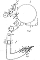
- a feeder device not of the invention is shown, by way of example only, incorporated within a round baler.
- a round baler is shown schematically by reference 1, and the construction and operation of such balers are well known to those of ordinary skill in the art, and need not be described in detail herein.
- the baler has a rotating tine type pick up rotor 2 which picks up cut material lying on the ground and supplies it to a cutting or chopping rotor 3.
- the material lying on the ground may be hay, straw, or wilted grass for use in forming silage.
- the chopped material is then fed by the rotor 3 to a bale-forming chamber 4, which forms and compresses the material by continuously turning and taking in the material so that a cylindrical bale of progressively increasing diameter is formed, until a big or round bale 7 of sufficient size has been formed, having a cylindrical outer surface 12.
- compression/transport rollers 5 and "apron" type belts 6 are used, according to known techniques.
- the feeding of new material to the chamber 4 is interrupted, but the bale 7 continues to rotate.
- the feeding of sheet material to cover at least the cylindrical outer surface 12 then takes places, and the covering sheet may be netting, or plastics film.
- the sheet material takes the form of plastics film 8, supplied from a supply reel 25.
- rollers 5a and 5b which define a feeding aperture 9 therebetween.
- the upper roller 5a is engaged by the apron belts 6, as shown, and forms a return end for the continuous movement of the belts around the outer periphery of the bale as it is being formed.
- the lower roller 5b is not engaged by the apron belts 6, and therefore it is possible to define a feeding aperture 9 between rollers 5a and 5b, through which the film 8 can be introduced, when it is required to apply a covering layer to the outer surface of the bale.
- a feeder device 13 is provided, in order to feed and guide the delivery of the film 8 from the supply reel 25 to the outer surface 12 of the bale 7 and or roller 5a/b.
- the device 13 in the illustrated arrangement, is pivotally mounted, and is shown in full lines in a withdrawn/inactive position, and is shown in dashed outline in its feeding position, which it takes up after pivoting through approximately 90° about an upper horizontal pivot 13b.
- Figure 3 shows the feeder device 13 in the withdrawn position, whereas Figure 4 shows it in its feeding position.
- the device 13 comprises two plates 14 interconnected by a transverse bar 15, and which extend throughout the width of the bale chamber 4, measured along the axis of rotation of the bale 7.
- the feeder device 13 has a feeding mouth 11, through which the film 8 is taken in order to engage with the outer surface 12 of the bale 7, after passing through the feeding aperture 9 defined between rollers 5a and 5b.
- the feeding mouth 11 essentially comprises a pair of cooperating elastomeric lips; of which upper lip 16a is connected to a screen 17 connected to the lower end of the forward one of the pair of metal plates 14, whereas lower lip16b is connected to transversely extending edge bar 18.
- the lips 16a, 16b extend throughout the full axial extent of the bale, and conveniently are made of rubber reinforced by textile material in web form. By such an arrangement, the lips 16a, 16b have a specific stable shape, but are resiliently deformable from the defined shape under load.
- the upper lip 16a has a lower engaging surface 16d, engaging with the upper surface 8a of film 8, and surface 16d is roughly textured, for example by perforation, or provision of blister pads, to provide firm gripping engagement, but prevent adhesion between the film and the lip.
- a silicone layer may be provided on the facing surface 16d.
- rollers 19 and 20 Adjacent to the lips 16a and 16b, there are arranged two cooperating rollers 19 and 20, whose axes of rotation extend generally parallel to the axis of rotation of bale 7.
- the lower roller 20 is provided with a freewheel, which allows roller 20 to rotate only in the direction of the arrow 21, but prevents any rotation in a reverse direction.
- the upper roller 19 is freely rotatable in either direction.
- roller 19 could also be provided with a freewheel, if required.
- the outer surface of the roller 20, provided with a freewheel has a rough outer surface. The surface roughness/texture could be created by providing a sheet or film, for example a rubber film layer 20a.
- the opposed upper roller 19 is pivotally mounted on a support arm 22 which is rotatable about a horizontal pivot 23.
- the rollers 19 and 20 therefore are engaged firmly with each other, and are therefore able to hold the film 8 safely and reliably between them.
- the feeder device 13 is shown in the withdrawn position.
- the film 8 is pulled through and led between the rollers 19 and 20, and also remains held between the lips 16a, 16b, leaving a freely hanging leading end or "tail" 26.
- the feeder device 13 is in the withdrawn position of Figure 3 , the bale 17 continues to be formed, and during this time the rollers 5a and 5b rotate clockwise, as shown by the arrows.
- a required diameter which is adjustable, the picking up of crop material and supply to the chamber 4 is stopped. However, the bale 7 continues to be rotated.
- the feeder device 13 is now pivoted downwardly in an anticlockwise direction about upper pivot 13b, under the operation of an actuator 13a which is connected to device 13 pivotally via pivot mounting 27.
- the device 13 moves to the feeding position shown in Figure 4 , and in which the film 8 remains held firmly between the rollers 19 and 20, and with the leading end or tail 26 projecting forwardly therefrom, and into the feed gap 9 defined between rollers 5a and 5b.
- the film 8 is then capable of being safely firmly unwound from supply reel 25, and comes into contact with the material of the bale 7 on its outer surface 12 and or rollers 5a/b.
- the tensioning or stretching device could temporary (partly) be disengaged.
- the film 8 is arranged to be "tacky" on its contacting face, so that the film end 26 is able to adhere to the winding surface 12 of the bale 7, and is carried along with the bale in an anticlockwise direction shown by arrow 28. This is also assisted by the clockwise rotation of the lower roller 5b, which it also engages. As soon as the leading end 26 of the film 8 is securely engaging and moving with the cylindrical outer surface 12 of the bale 7, the feeder device 13 can then pivot back partly in the direction of its withdrawn position of Figure 3 , to take up an intermediate position shown in Figure 5 . The withdrawing is not causing extra force on the actuator since the tensioning force of the film is not added to the pulling back force.
- successive windings of covering layer can be applied to the surface 12 of the bale 7, by continued withdrawal of film 8 from the reel 25.
- the actuator 13a is operated to move the feeder device 13 back still further to the position shown in Figure 6 .
- This then allows a cutting mechanism to be operated, in order to cut the length of film 8 which runs between the feeding mouth (lips 16a and 16b) and the outer surface of the bale 7, thereby to form a new leading end 26 of film 8.
- the cutting mechanism comprises a rotating cutter roll 29 having radially projecting cutting pins 31 or cutting knife. Rotation of roll 29 through about 90° causes the pins 31 to penetrate the film 8 and tear it apart.
- the rollers 19 and 20 safely hold the newly formed film end 26, of which a forward end hangs freely from the mouth 11 defined by lips 16a and 16b.
- the film 8 has a width which corresponds at least to the entire width of the machine i.e. extends axially throughout the length at least of the bale 7 measured along its axis, so that the film 8 can cover the entire cylindrical outer surface 12. This is possible because of the full amount of free space made available in the design of the baler, and because also of the arrangement of the rollers 5.
- the screen 17 also extends throughout the full length of the feeder device 13. During feeding of film 8 onto the outer surface of the bale, it forms a shield over the exposed upper surface of the film 8 and rollers 19 and 20, and is therefore able to catch any dust which is inevitably present, and which might otherwise fall onto the surface of the film. When the feeder device 13 reverses to its withdrawn or inactive position, any dust which has been collected falls off, and therefore there is a self-cleaning function during each operating cycle.
- the pivotable mounting of the feeding device 13, in the illustrated embodiment is one mode of mounting only. It is within the scope of the invention for the feeder device to be mounted so as to be capable of movement such that the feeder mouth 11 moves along a linear path, both forward and reverse. Regardless of the way in which the feeder device 13 is mounted, the functional features performed by the rollers 19 and 20, and the flexible lips 16a, 16b, and also the cutting rotor 29, are able to perform with all the same technical advantages.
- feeder device 13 therefore has a feeder mouth 11 which is mounted on a support (14, 15, 17), and means 13b is provided to mount the support 14, 15, 17 on the device 13 for movement between an inoperative withdrawn position (in which the feeder mouth 11 is spaced from the outer surface 12 of the bale 7 and with a leading end 26 of the sheet 8 projecting from the feeder mouth 11), and a feeding position in which the feeder mouth 11 is adjacent to the outer surface 12 of the bale 7 so that the leading end 26 of the sheet 8 can engage with the outer surface 12 of the bale 7. and or rollers 5a/b.
- roller 19, 20 mounted on the support 14, 15, 17 and located along the path of travel of the sheet 8 from the supply 25 to the feeder mouth 11, so as to be engageable with opposed faces of the sheet 8 and thereby hold the leading end 26 of the sheet 8 when the support 14, 15, 17 is in its inoperative withdrawn position, and also as it moves to its feeding position. Further, the holding action of the roller 19, 20 is capable of being overcome upon engagement of the sheet 8 with the outer surface 12 of the bale 7 and consequent pulling force being exerted upon the sheet 8.
- rollers 19, 20 are shown in close proximity to each other, and with the sheet (film) 8 being fed in a sinuous manner engaging part of the outer periphery of clockwise rotating roller 19, and a part of the periphery of roller 20 which rotates in an anticlockwise direction.
- the axis of rotation of roller 20 is located downstream of the axis of roller 19, with respect to the path of travel of the film 8 through the feeder device. This to have more grip on the film/net without excessive pressing forces of the rollers onto each other, by the long contact surface between film and rollers,
- FIG. 9 shows an alternative arrangement, in which rollers 19 and 20 do not contact each other, but there is a small gap therebetween. As to abandon fully the pressing force between the roller, which may therefore be designed lighter. However, the path of travel of the film 8 is generally similar. For the good grip.
- the embodiment of Figure 10 shows rollers 190 and 200, arranged closely adjacent to each other, similar to the embodiment of Figure9 , and similar path of travel of the film 8.
- rollers 190 and 200 there is a gear drive connection between the rollers 190 and 200, with roller 200 rotating at a higher peripheral speed, so as to apply a pre-stretching action to the film 8, prior to issue from the feeding mouth 11 and wrapping around the outer surface of the bale.
- a convenient peripheral speed ratio between rollers 190 and 200 is 1:1.6. Hydraulic drive may be applied to the roller 190 or 200 as to lower the pulling off force on the film by the bale, and then the gear drive from roller 190 to roller 200 applies the required speed multiplication to the roller 200.
- FIG 11 shows an arrangement similar to that of Figure 9 i.e. the rollers 19 and 20 have their axes of rotation spaced apart with respect to the general path of travel of the film 8 through the feeding device, but in this embodiment each of the rollers 19, 20 is driven by its own motor, which can be an electric motor or hydraulic motor.
- the drive arrangement is such that the peripheral speed of roller 20 is faster than the peripheral speed of roller 19, again preferably in a ratio of 1:1.6, in order to act as a pre-stretcher mechanism and or can support to lower the pulling force on the film by the bale.
- FIG 12 shows application of a feeder device according to the invention, in combination with a bale handling apparatus which is used to support and to rotate a bale of rectangular cross-section (parallelepiped) shape.
- the bale handling apparatus is shown schematically only, and may be a set of four support rollers of the type provided in a bale wrapper apparatus for applying stretch film to the outer periphery of a rectangular cross-section bale.
- Figures 13 and 14 illustrate an embodiment of the invention and show schematically, in side view and plan view respectively, the relative width of a sheet of film being applied to the outer surface of a cylindrical bale, relative to the axial extent (the width) of the bale which is being covered.
- the entire cylindrical surface of the bale can be covered, and when the sheet being supplied has a greater width than the axial extent of the bale, it is possible for the sheet covering also to overlap the circular edges at each end of the bale, and partly to overlie a circumferential region of the circular end faces of the bale.
- Figure 13 right hand shows a feeder device in a somewhat retracted position as described earlier.
- the film 8 is running over an angle over a non-flexible lip 16A and the edges of the film/net are short cutting (8A) this angle. Because the leading end 16A' of lip 16A is smaller as the width of the film and the base width, to which the leading end is extending, the film/net is upsetting, curling the net/film towards the sides, which upset/curled up film/net is put just on the edge of the cylindrical side of the bale.
Landscapes
- Life Sciences & Earth Sciences (AREA)
- Environmental Sciences (AREA)
- Storage Of Harvested Produce (AREA)
Priority Applications (1)
| Application Number | Priority Date | Filing Date | Title |
|---|---|---|---|
| PL10010427T PL2266386T5 (pl) | 2003-07-31 | 2004-07-30 | Podajnik materiału do pokrywania zewnętrznej powierzchni beli rolniczej |
Applications Claiming Priority (3)
| Application Number | Priority Date | Filing Date | Title |
|---|---|---|---|
| DE10334987 | 2003-07-31 | ||
| DE102004001773A DE102004001773A1 (de) | 2003-07-31 | 2004-01-12 | Vorrichtung an einer Rundballenpresse |
| EP04769103.5A EP1648217B1 (en) | 2003-07-31 | 2004-07-30 | Covering sheet feeder device for covering the outer surface of an agricultural bale |
Related Parent Applications (2)
| Application Number | Title | Priority Date | Filing Date |
|---|---|---|---|
| EP04769103.5A Division EP1648217B1 (en) | 2003-07-31 | 2004-07-30 | Covering sheet feeder device for covering the outer surface of an agricultural bale |
| EP04769103.5 Division | 2004-07-30 |
Publications (4)
| Publication Number | Publication Date |
|---|---|
| EP2266386A2 EP2266386A2 (en) | 2010-12-29 |
| EP2266386A3 EP2266386A3 (en) | 2014-01-15 |
| EP2266386B1 EP2266386B1 (en) | 2014-09-10 |
| EP2266386B2 true EP2266386B2 (en) | 2017-09-20 |
Family
ID=34088979
Family Applications (1)
| Application Number | Title | Priority Date | Filing Date |
|---|---|---|---|
| EP10010427.2A Expired - Lifetime EP2266386B2 (en) | 2003-07-31 | 2004-07-30 | Covering sheet feeder device for covering the outer surface of an agricultural bale |
Country Status (3)
| Country | Link |
|---|---|
| EP (1) | EP2266386B2 (pl) |
| DE (1) | DE102004001773A1 (pl) |
| PL (1) | PL2266386T5 (pl) |
Cited By (2)
| Publication number | Priority date | Publication date | Assignee | Title |
|---|---|---|---|---|
| US11032974B2 (en) * | 2017-02-24 | 2021-06-15 | Deere & Company | External belt guide for round baler |
| US11039575B2 (en) * | 2017-02-24 | 2021-06-22 | Deere & Company | External belt guide for round baler |
Families Citing this family (6)
| Publication number | Priority date | Publication date | Assignee | Title |
|---|---|---|---|---|
| EP2113165B1 (en) | 2008-04-30 | 2011-08-24 | Deere & Company | Web wrap device |
| DE202015003273U1 (de) | 2015-05-04 | 2016-08-05 | Alois Pöttinger Maschinenfabrik Ges.m.b.H. | Ballenpresse für landwirtschaftliches Erntegut |
| DE102017122138A1 (de) * | 2017-09-25 | 2019-03-28 | Usines Claas France S.A.S. | Zuführeinrichtung zur Zuführung von Wickelmaterial in eine Presskammer einer Rundballenpresse |
| GB2594457A (en) * | 2020-04-27 | 2021-11-03 | Kuhn Geldrop Bv | Round baler |
| EP4091434A1 (en) * | 2021-05-10 | 2022-11-23 | AGCO International GmbH | Baling apparatus |
| DE102024104281A1 (de) | 2024-02-15 | 2025-08-21 | Usines Claas France S.A.S | Zuführvorrichtung zur Zuführung von Wickelmaterial in eine Presskammer einer Rundballenpresse |
Family Cites Families (7)
| Publication number | Priority date | Publication date | Assignee | Title |
|---|---|---|---|---|
| DE69015338T2 (de) | 1989-12-11 | 1995-05-18 | Ford New Holland Nv | Ballenumwickelvorrichtung für Rundballenpressen. |
| US5243806A (en) * | 1992-08-10 | 1993-09-14 | Ford New Holland, Inc. | Apparatus for wrapping round bales with sheet material |
| US6006504A (en) * | 1998-01-16 | 1999-12-28 | Deere & Company | Large round baler having wrapping mechanism for placing net over edges of bale |
| US6021622A (en) * | 1998-06-19 | 2000-02-08 | New Holland North America, Inc. | Round bale wrapping apparatus |
| US6606843B1 (en) * | 2000-03-21 | 2003-08-19 | Deere & Company | Structure for reliably feeding and spreading net wrap material, of a width greater than the width of a round baler chamber, so as to cover opposite end segments of a bale located in the chamber |
| DE10211412A1 (de) * | 2002-03-15 | 2003-10-09 | Deere & Co | Rundballenpresse |
| GB2438610A (en) * | 2006-06-02 | 2007-12-05 | Cnh Belgium Nv | Round baler with changeable wrapping width |
-
2004
- 2004-01-12 DE DE102004001773A patent/DE102004001773A1/de not_active Withdrawn
- 2004-07-30 PL PL10010427T patent/PL2266386T5/pl unknown
- 2004-07-30 EP EP10010427.2A patent/EP2266386B2/en not_active Expired - Lifetime
Cited By (2)
| Publication number | Priority date | Publication date | Assignee | Title |
|---|---|---|---|---|
| US11032974B2 (en) * | 2017-02-24 | 2021-06-15 | Deere & Company | External belt guide for round baler |
| US11039575B2 (en) * | 2017-02-24 | 2021-06-22 | Deere & Company | External belt guide for round baler |
Also Published As
| Publication number | Publication date |
|---|---|
| PL2266386T5 (pl) | 2018-03-30 |
| EP2266386A3 (en) | 2014-01-15 |
| DE102004001773A1 (de) | 2005-02-24 |
| EP2266386B1 (en) | 2014-09-10 |
| EP2266386A2 (en) | 2010-12-29 |
| PL2266386T3 (pl) | 2014-12-31 |
Similar Documents
| Publication | Publication Date | Title |
|---|---|---|
| EP1648217B1 (en) | Covering sheet feeder device for covering the outer surface of an agricultural bale | |
| US7513088B2 (en) | Bale wrapping apparatus | |
| US6050052A (en) | Round baler having positive start wrapper dispensing mechanism | |
| US5319899A (en) | Net severing apparatus for round baler | |
| US5365836A (en) | Apparatus for wrapping round bales | |
| EP2266386B2 (en) | Covering sheet feeder device for covering the outer surface of an agricultural bale | |
| JPH02258197A (ja) | わら材圧縮成形物の製造方法及び装置 | |
| EP3111747B1 (en) | Wrapping apparatus and method with a wrapping material severing device comprising an own actuator | |
| US5448873A (en) | Net knife for round baler | |
| EP4151075B1 (en) | Baler | |
| EP3539369B1 (en) | Material wrap system with self cleaning feature | |
| EP2769615B1 (en) | Apparatus and method for pushing wrapping material into a chamber | |
| GB2594457A (en) | Round baler | |
| EP3370503B1 (en) | Bale forming and wrapping apparatus and method with a pivotal web pusher | |
| EP3270682B1 (en) | Bale forming and wrapping apparatus with a guided web moving member | |
| EP0672340B1 (en) | Round bale wrapping apparatus and method | |
| EP3672394B1 (en) | A method for operating a round baler and a round baler | |
| EP3874935B1 (en) | Agricultural baler with wrapping material knife to reduce rotor wrap-around | |
| EP4144205B1 (en) | Round baler | |
| US5419241A (en) | Tape dispensing apparatus for round balers | |
| US20180368329A1 (en) | Enveloping device for enveloping a bale with an enveloping material, a baler, and method thereof | |
| GB2598590A (en) | Round baler |
Legal Events
| Date | Code | Title | Description |
|---|---|---|---|
| PUAI | Public reference made under article 153(3) epc to a published international application that has entered the european phase |
Free format text: ORIGINAL CODE: 0009012 |
|
| AC | Divisional application: reference to earlier application |
Ref document number: 1648217 Country of ref document: EP Kind code of ref document: P |
|
| AK | Designated contracting states |
Kind code of ref document: A2 Designated state(s): AT BE BG CH CY CZ DE DK EE ES FI FR GB GR HU IE IT LI LU MC NL PL PT RO SE SI SK TR |
|
| PUAL | Search report despatched |
Free format text: ORIGINAL CODE: 0009013 |
|
| AK | Designated contracting states |
Kind code of ref document: A3 Designated state(s): AT BE BG CH CY CZ DE DK EE ES FI FR GB GR HU IE IT LI LU MC NL PL PT RO SE SI SK TR |
|
| RIC1 | Information provided on ipc code assigned before grant |
Ipc: A01F 15/07 20060101AFI20131209BHEP |
|
| 17P | Request for examination filed |
Effective date: 20140211 |
|
| RBV | Designated contracting states (corrected) |
Designated state(s): AT BE BG CH CY CZ DE DK EE ES FI FR GB GR HU IE IT LI LU MC NL PL PT RO SE SI SK TR |
|
| GRAP | Despatch of communication of intention to grant a patent |
Free format text: ORIGINAL CODE: EPIDOSNIGR1 |
|
| INTG | Intention to grant announced |
Effective date: 20140502 |
|
| GRAS | Grant fee paid |
Free format text: ORIGINAL CODE: EPIDOSNIGR3 |
|
| GRAA | (expected) grant |
Free format text: ORIGINAL CODE: 0009210 |
|
| AC | Divisional application: reference to earlier application |
Ref document number: 1648217 Country of ref document: EP Kind code of ref document: P |
|
| AK | Designated contracting states |
Kind code of ref document: B1 Designated state(s): AT BE BG CH CY CZ DE DK EE ES FI FR GB GR HU IE IT LI LU MC NL PL PT RO SE SI SK TR |
|
| REG | Reference to a national code |
Ref country code: GB Ref legal event code: FG4D |
|
| REG | Reference to a national code |
Ref country code: CH Ref legal event code: EP |
|
| REG | Reference to a national code |
Ref country code: IE Ref legal event code: FG4D |
|
| REG | Reference to a national code |
Ref country code: AT Ref legal event code: REF Ref document number: 686186 Country of ref document: AT Kind code of ref document: T Effective date: 20141015 |
|
| REG | Reference to a national code |
Ref country code: DE Ref legal event code: R096 Ref document number: 602004045824 Country of ref document: DE Effective date: 20141030 |
|
| REG | Reference to a national code |
Ref country code: SE Ref legal event code: TRGR |
|
| REG | Reference to a national code |
Ref country code: PL Ref legal event code: T3 |
|
| PG25 | Lapsed in a contracting state [announced via postgrant information from national office to epo] |
Ref country code: GR Free format text: LAPSE BECAUSE OF FAILURE TO SUBMIT A TRANSLATION OF THE DESCRIPTION OR TO PAY THE FEE WITHIN THE PRESCRIBED TIME-LIMIT Effective date: 20141211 Ref country code: ES Free format text: LAPSE BECAUSE OF FAILURE TO SUBMIT A TRANSLATION OF THE DESCRIPTION OR TO PAY THE FEE WITHIN THE PRESCRIBED TIME-LIMIT Effective date: 20140910 Ref country code: FI Free format text: LAPSE BECAUSE OF FAILURE TO SUBMIT A TRANSLATION OF THE DESCRIPTION OR TO PAY THE FEE WITHIN THE PRESCRIBED TIME-LIMIT Effective date: 20140910 |
|
| REG | Reference to a national code |
Ref country code: NL Ref legal event code: VDEP Effective date: 20140910 |
|
| PG25 | Lapsed in a contracting state [announced via postgrant information from national office to epo] |
Ref country code: CY Free format text: LAPSE BECAUSE OF FAILURE TO SUBMIT A TRANSLATION OF THE DESCRIPTION OR TO PAY THE FEE WITHIN THE PRESCRIBED TIME-LIMIT Effective date: 20140910 |
|
| PG25 | Lapsed in a contracting state [announced via postgrant information from national office to epo] |
Ref country code: NL Free format text: LAPSE BECAUSE OF FAILURE TO SUBMIT A TRANSLATION OF THE DESCRIPTION OR TO PAY THE FEE WITHIN THE PRESCRIBED TIME-LIMIT Effective date: 20140910 |
|
| PG25 | Lapsed in a contracting state [announced via postgrant information from national office to epo] |
Ref country code: PT Free format text: LAPSE BECAUSE OF FAILURE TO SUBMIT A TRANSLATION OF THE DESCRIPTION OR TO PAY THE FEE WITHIN THE PRESCRIBED TIME-LIMIT Effective date: 20150112 Ref country code: EE Free format text: LAPSE BECAUSE OF FAILURE TO SUBMIT A TRANSLATION OF THE DESCRIPTION OR TO PAY THE FEE WITHIN THE PRESCRIBED TIME-LIMIT Effective date: 20140910 Ref country code: SK Free format text: LAPSE BECAUSE OF FAILURE TO SUBMIT A TRANSLATION OF THE DESCRIPTION OR TO PAY THE FEE WITHIN THE PRESCRIBED TIME-LIMIT Effective date: 20140910 Ref country code: CZ Free format text: LAPSE BECAUSE OF FAILURE TO SUBMIT A TRANSLATION OF THE DESCRIPTION OR TO PAY THE FEE WITHIN THE PRESCRIBED TIME-LIMIT Effective date: 20140910 Ref country code: RO Free format text: LAPSE BECAUSE OF FAILURE TO SUBMIT A TRANSLATION OF THE DESCRIPTION OR TO PAY THE FEE WITHIN THE PRESCRIBED TIME-LIMIT Effective date: 20140910 |
|
| REG | Reference to a national code |
Ref country code: DE Ref legal event code: R026 Ref document number: 602004045824 Country of ref document: DE |
|
| PLBI | Opposition filed |
Free format text: ORIGINAL CODE: 0009260 |
|
| PLAX | Notice of opposition and request to file observation + time limit sent |
Free format text: ORIGINAL CODE: EPIDOSNOBS2 |
|
| 26 | Opposition filed |
Opponent name: DEERE & COMPANY Effective date: 20150610 |
|
| PG25 | Lapsed in a contracting state [announced via postgrant information from national office to epo] |
Ref country code: DK Free format text: LAPSE BECAUSE OF FAILURE TO SUBMIT A TRANSLATION OF THE DESCRIPTION OR TO PAY THE FEE WITHIN THE PRESCRIBED TIME-LIMIT Effective date: 20140910 |
|
| PLBB | Reply of patent proprietor to notice(s) of opposition received |
Free format text: ORIGINAL CODE: EPIDOSNOBS3 |
|
| PG25 | Lapsed in a contracting state [announced via postgrant information from national office to epo] |
Ref country code: SI Free format text: LAPSE BECAUSE OF FAILURE TO SUBMIT A TRANSLATION OF THE DESCRIPTION OR TO PAY THE FEE WITHIN THE PRESCRIBED TIME-LIMIT Effective date: 20140910 |
|
| PG25 | Lapsed in a contracting state [announced via postgrant information from national office to epo] |
Ref country code: MC Free format text: LAPSE BECAUSE OF FAILURE TO SUBMIT A TRANSLATION OF THE DESCRIPTION OR TO PAY THE FEE WITHIN THE PRESCRIBED TIME-LIMIT Effective date: 20140910 |
|
| REG | Reference to a national code |
Ref country code: CH Ref legal event code: PL |
|
| PG25 | Lapsed in a contracting state [announced via postgrant information from national office to epo] |
Ref country code: LU Free format text: LAPSE BECAUSE OF FAILURE TO SUBMIT A TRANSLATION OF THE DESCRIPTION OR TO PAY THE FEE WITHIN THE PRESCRIBED TIME-LIMIT Effective date: 20150730 |
|
| PG25 | Lapsed in a contracting state [announced via postgrant information from national office to epo] |
Ref country code: CH Free format text: LAPSE BECAUSE OF NON-PAYMENT OF DUE FEES Effective date: 20150731 Ref country code: LI Free format text: LAPSE BECAUSE OF NON-PAYMENT OF DUE FEES Effective date: 20150731 |
|
| REG | Reference to a national code |
Ref country code: FR Ref legal event code: PLFP Year of fee payment: 13 |
|
| PG25 | Lapsed in a contracting state [announced via postgrant information from national office to epo] |
Ref country code: BE Free format text: LAPSE BECAUSE OF FAILURE TO SUBMIT A TRANSLATION OF THE DESCRIPTION OR TO PAY THE FEE WITHIN THE PRESCRIBED TIME-LIMIT Effective date: 20140910 |
|
| PG25 | Lapsed in a contracting state [announced via postgrant information from national office to epo] |
Ref country code: BG Free format text: LAPSE BECAUSE OF FAILURE TO SUBMIT A TRANSLATION OF THE DESCRIPTION OR TO PAY THE FEE WITHIN THE PRESCRIBED TIME-LIMIT Effective date: 20140910 Ref country code: HU Free format text: LAPSE BECAUSE OF FAILURE TO SUBMIT A TRANSLATION OF THE DESCRIPTION OR TO PAY THE FEE WITHIN THE PRESCRIBED TIME-LIMIT; INVALID AB INITIO Effective date: 20040730 |
|
| REG | Reference to a national code |
Ref country code: FR Ref legal event code: PLFP Year of fee payment: 14 |
|
| PUAH | Patent maintained in amended form |
Free format text: ORIGINAL CODE: 0009272 |
|
| STAA | Information on the status of an ep patent application or granted ep patent |
Free format text: STATUS: PATENT MAINTAINED AS AMENDED |
|
| 27A | Patent maintained in amended form |
Effective date: 20170920 |
|
| AK | Designated contracting states |
Kind code of ref document: B2 Designated state(s): AT BE BG CH CY CZ DE DK EE ES FI FR GB GR HU IE IT LI LU MC NL PL PT RO SE SI SK TR |
|
| REG | Reference to a national code |
Ref country code: DE Ref legal event code: R102 Ref document number: 602004045824 Country of ref document: DE |
|
| REG | Reference to a national code |
Ref country code: SE Ref legal event code: RPEO |
|
| REG | Reference to a national code |
Ref country code: FR Ref legal event code: PLFP Year of fee payment: 15 |
|
| PGFP | Annual fee paid to national office [announced via postgrant information from national office to epo] |
Ref country code: IT Payment date: 20190726 Year of fee payment: 16 Ref country code: SE Payment date: 20190729 Year of fee payment: 16 Ref country code: TR Payment date: 20190709 Year of fee payment: 16 |
|
| PGFP | Annual fee paid to national office [announced via postgrant information from national office to epo] |
Ref country code: AT Payment date: 20190703 Year of fee payment: 16 |
|
| REG | Reference to a national code |
Ref country code: AT Ref legal event code: UEP Ref document number: 686186 Country of ref document: AT Kind code of ref document: T Effective date: 20170920 |
|
| REG | Reference to a national code |
Ref country code: SE Ref legal event code: EUG |
|
| REG | Reference to a national code |
Ref country code: AT Ref legal event code: MM01 Ref document number: 686186 Country of ref document: AT Kind code of ref document: T Effective date: 20200730 |
|
| PG25 | Lapsed in a contracting state [announced via postgrant information from national office to epo] |
Ref country code: AT Free format text: LAPSE BECAUSE OF NON-PAYMENT OF DUE FEES Effective date: 20200730 Ref country code: SE Free format text: LAPSE BECAUSE OF NON-PAYMENT OF DUE FEES Effective date: 20200731 |
|
| PG25 | Lapsed in a contracting state [announced via postgrant information from national office to epo] |
Ref country code: IT Free format text: LAPSE BECAUSE OF NON-PAYMENT OF DUE FEES Effective date: 20200730 |
|
| PGFP | Annual fee paid to national office [announced via postgrant information from national office to epo] |
Ref country code: GB Payment date: 20210727 Year of fee payment: 18 |
|
| PG25 | Lapsed in a contracting state [announced via postgrant information from national office to epo] |
Ref country code: TR Free format text: LAPSE BECAUSE OF NON-PAYMENT OF DUE FEES Effective date: 20200730 |
|
| GBPC | Gb: european patent ceased through non-payment of renewal fee |
Effective date: 20220730 |
|
| PG25 | Lapsed in a contracting state [announced via postgrant information from national office to epo] |
Ref country code: GB Free format text: LAPSE BECAUSE OF NON-PAYMENT OF DUE FEES Effective date: 20220730 |
|
| PGFP | Annual fee paid to national office [announced via postgrant information from national office to epo] |
Ref country code: IE Payment date: 20230727 Year of fee payment: 20 |
|
| PGFP | Annual fee paid to national office [announced via postgrant information from national office to epo] |
Ref country code: PL Payment date: 20230705 Year of fee payment: 20 Ref country code: FR Payment date: 20230725 Year of fee payment: 20 Ref country code: DE Payment date: 20230727 Year of fee payment: 20 |
|
| REG | Reference to a national code |
Ref country code: DE Ref legal event code: R071 Ref document number: 602004045824 Country of ref document: DE |
|
| REG | Reference to a national code |
Ref country code: IE Ref legal event code: MK9A |
|
| PG25 | Lapsed in a contracting state [announced via postgrant information from national office to epo] |
Ref country code: IE Free format text: LAPSE BECAUSE OF EXPIRATION OF PROTECTION Effective date: 20240730 |
|
| PG25 | Lapsed in a contracting state [announced via postgrant information from national office to epo] |
Ref country code: IE Free format text: LAPSE BECAUSE OF EXPIRATION OF PROTECTION Effective date: 20240730 |