EP2265447B1 - Method for producing vehicle wheel hubs and wheel hubs made using this method - Google Patents
Method for producing vehicle wheel hubs and wheel hubs made using this method Download PDFInfo
- Publication number
- EP2265447B1 EP2265447B1 EP09722903A EP09722903A EP2265447B1 EP 2265447 B1 EP2265447 B1 EP 2265447B1 EP 09722903 A EP09722903 A EP 09722903A EP 09722903 A EP09722903 A EP 09722903A EP 2265447 B1 EP2265447 B1 EP 2265447B1
- Authority
- EP
- European Patent Office
- Prior art keywords
- ring
- spindle
- lobe
- shoulder
- parts
- Prior art date
- Legal status (The legal status is an assumption and is not a legal conclusion. Google has not performed a legal analysis and makes no representation as to the accuracy of the status listed.)
- Not-in-force
Links
Images

Classifications
-
- B—PERFORMING OPERATIONS; TRANSPORTING
- B60—VEHICLES IN GENERAL
- B60B—VEHICLE WHEELS; CASTORS; AXLES FOR WHEELS OR CASTORS; INCREASING WHEEL ADHESION
- B60B27/00—Hubs
-
- F—MECHANICAL ENGINEERING; LIGHTING; HEATING; WEAPONS; BLASTING
- F16—ENGINEERING ELEMENTS AND UNITS; GENERAL MEASURES FOR PRODUCING AND MAINTAINING EFFECTIVE FUNCTIONING OF MACHINES OR INSTALLATIONS; THERMAL INSULATION IN GENERAL
- F16C—SHAFTS; FLEXIBLE SHAFTS; ELEMENTS OR CRANKSHAFT MECHANISMS; ROTARY BODIES OTHER THAN GEARING ELEMENTS; BEARINGS
- F16C19/00—Bearings with rolling contact, for exclusively rotary movement
- F16C19/02—Bearings with rolling contact, for exclusively rotary movement with bearing balls essentially of the same size in one or more circular rows
- F16C19/14—Bearings with rolling contact, for exclusively rotary movement with bearing balls essentially of the same size in one or more circular rows for both radial and axial load
- F16C19/18—Bearings with rolling contact, for exclusively rotary movement with bearing balls essentially of the same size in one or more circular rows for both radial and axial load with two or more rows of balls
- F16C19/181—Bearings with rolling contact, for exclusively rotary movement with bearing balls essentially of the same size in one or more circular rows for both radial and axial load with two or more rows of balls with angular contact
- F16C19/183—Bearings with rolling contact, for exclusively rotary movement with bearing balls essentially of the same size in one or more circular rows for both radial and axial load with two or more rows of balls with angular contact with two rows at opposite angles
- F16C19/184—Bearings with rolling contact, for exclusively rotary movement with bearing balls essentially of the same size in one or more circular rows for both radial and axial load with two or more rows of balls with angular contact with two rows at opposite angles in O-arrangement
- F16C19/185—Bearings with rolling contact, for exclusively rotary movement with bearing balls essentially of the same size in one or more circular rows for both radial and axial load with two or more rows of balls with angular contact with two rows at opposite angles in O-arrangement with two raceways provided integrally on a part other than a race ring, e.g. a shaft or housing
-
- F—MECHANICAL ENGINEERING; LIGHTING; HEATING; WEAPONS; BLASTING
- F16—ENGINEERING ELEMENTS AND UNITS; GENERAL MEASURES FOR PRODUCING AND MAINTAINING EFFECTIVE FUNCTIONING OF MACHINES OR INSTALLATIONS; THERMAL INSULATION IN GENERAL
- F16C—SHAFTS; FLEXIBLE SHAFTS; ELEMENTS OR CRANKSHAFT MECHANISMS; ROTARY BODIES OTHER THAN GEARING ELEMENTS; BEARINGS
- F16C19/00—Bearings with rolling contact, for exclusively rotary movement
- F16C19/02—Bearings with rolling contact, for exclusively rotary movement with bearing balls essentially of the same size in one or more circular rows
- F16C19/14—Bearings with rolling contact, for exclusively rotary movement with bearing balls essentially of the same size in one or more circular rows for both radial and axial load
- F16C19/18—Bearings with rolling contact, for exclusively rotary movement with bearing balls essentially of the same size in one or more circular rows for both radial and axial load with two or more rows of balls
- F16C19/181—Bearings with rolling contact, for exclusively rotary movement with bearing balls essentially of the same size in one or more circular rows for both radial and axial load with two or more rows of balls with angular contact
- F16C19/183—Bearings with rolling contact, for exclusively rotary movement with bearing balls essentially of the same size in one or more circular rows for both radial and axial load with two or more rows of balls with angular contact with two rows at opposite angles
- F16C19/184—Bearings with rolling contact, for exclusively rotary movement with bearing balls essentially of the same size in one or more circular rows for both radial and axial load with two or more rows of balls with angular contact with two rows at opposite angles in O-arrangement
- F16C19/186—Bearings with rolling contact, for exclusively rotary movement with bearing balls essentially of the same size in one or more circular rows for both radial and axial load with two or more rows of balls with angular contact with two rows at opposite angles in O-arrangement with three raceways provided integrally on parts other than race rings, e.g. third generation hubs
-
- F—MECHANICAL ENGINEERING; LIGHTING; HEATING; WEAPONS; BLASTING
- F16—ENGINEERING ELEMENTS AND UNITS; GENERAL MEASURES FOR PRODUCING AND MAINTAINING EFFECTIVE FUNCTIONING OF MACHINES OR INSTALLATIONS; THERMAL INSULATION IN GENERAL
- F16C—SHAFTS; FLEXIBLE SHAFTS; ELEMENTS OR CRANKSHAFT MECHANISMS; ROTARY BODIES OTHER THAN GEARING ELEMENTS; BEARINGS
- F16C35/00—Rigid support of bearing units; Housings, e.g. caps, covers
- F16C35/04—Rigid support of bearing units; Housings, e.g. caps, covers in the case of ball or roller bearings
- F16C35/06—Mounting or dismounting of ball or roller bearings; Fixing them onto shaft or in housing
- F16C35/063—Fixing them on the shaft
-
- F—MECHANICAL ENGINEERING; LIGHTING; HEATING; WEAPONS; BLASTING
- F16—ENGINEERING ELEMENTS AND UNITS; GENERAL MEASURES FOR PRODUCING AND MAINTAINING EFFECTIVE FUNCTIONING OF MACHINES OR INSTALLATIONS; THERMAL INSULATION IN GENERAL
- F16C—SHAFTS; FLEXIBLE SHAFTS; ELEMENTS OR CRANKSHAFT MECHANISMS; ROTARY BODIES OTHER THAN GEARING ELEMENTS; BEARINGS
- F16C43/00—Assembling bearings
- F16C43/04—Assembling rolling-contact bearings
-
- F—MECHANICAL ENGINEERING; LIGHTING; HEATING; WEAPONS; BLASTING
- F16—ENGINEERING ELEMENTS AND UNITS; GENERAL MEASURES FOR PRODUCING AND MAINTAINING EFFECTIVE FUNCTIONING OF MACHINES OR INSTALLATIONS; THERMAL INSULATION IN GENERAL
- F16C—SHAFTS; FLEXIBLE SHAFTS; ELEMENTS OR CRANKSHAFT MECHANISMS; ROTARY BODIES OTHER THAN GEARING ELEMENTS; BEARINGS
- F16C2326/00—Articles relating to transporting
- F16C2326/01—Parts of vehicles in general
- F16C2326/02—Wheel hubs or castors
Definitions
- the invention relates to vehicle wheel hubs, namely to those case-like structures with bearings which support the wheel and the brake disc and which are designed to be constrained in a fixed or articulated manner to the rear axle unit or the front axle unit of a motor vehicle.
- the invention relates to the wheel hubs of the type shown in Figure 1 of the accompanying set of drawings, provided with a spindle 1 which supports integrally at one end a perpendicular flange 101 and which, via two interposed crown parts 2, 102 of revolving bodies consisting, for example, of spheres or other equivalent means such as, for example, cylindrical or conical needle rollers, cooperates with the possibility of a relative rotational movement, about the common axis A, with an outer crown part 3 usually provided with support lugs 103 connected for example to the front axle unit or rear axle unit of the motor vehicle, while the said flange 101 is designed in any suitable way to support the brake disc and rim of the wheel.
- the scope of the invention also includes wheel hubs similar or equivalent to that shown in Figure 1 and used also in a different manner, for example for connection by means of the spindle 1 to the supporting parts and for connection to the wheel and to the brake disc by means of the bush 3.
- the crown part of the rolling means 2 travels along an annular track 4 formed directly on the outer side surface of the spindle 1, while the other crown part of rolling means 102 travels along an annular track 104 formed on a ring 5 which is mounted on an externally tapered portion 201 of the spindle 1 and is firmly fixed onto the latter by means of abutment against an inner shoulder 6 and against an outer edge 201' formed, during a step following said mounting operation, by means of rolling of the section, projecting from the ring 5, of the said support portion 201 of the spindle.
- the space inside which the crown parts of the rolling means 2, 102 operate is filled with lubricant and is closed by known sealing means 7, 107.
- this solution offers the advantage compared to the previous solution of being able to be produced with very low costs, on the other hand it results in difficulties during engagement between the parts 5 and 1, owing to the need to correctly align these same parts relative to each other, both in the axial direction and in the angular direction, even before they are axially engaged together.
- EP 0 927 651 A2 discloses a vehicle wheel bearing-hub unit of the type comprising a dual ring of balls, in which the radially inner and axially outer race is formed in a separate annular component inserted on the hub, where the annular component is axially engaged on the hub by means of an annular end portion of the hub which is folded by means of cold forming.
- the surface of the annular component presents radial roughness means such that in performing the cold forming, the folded portion is deformed by the roughness means and reproduces the shape thereof, whereby the annular component is secured for rotation with the hub.
- the object of the invention is to solve this technical problem of engagement, in particular to simplify this engagement operation and simplify the formation of the keying means, with a method as described in Claim 1 and in the subsequent dependent claims, based on the following proposed solution: the machining operation for the three-lobe engaged arrangement is performed so as to involve all or only partly the shoulder 6 and the corresponding inner end of the ring 5, so that the latter may be mounted on the portion 201 of the spindle 1 as though these two parts were two normal parts with a round cross-section and therefore without any need for relative angular alignment and, only after these two parts have been engaged together axially, is a relative rotation of the said parts performed in order to engage correctly the three-lobe profile of the ring 5 with the corresponding three-lobe profile of the shoulder 6 of the spindle and vice versa and, after this step involving correct angular alignment, the said axial locking edge 201' will be formed by means of rolling.
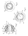
- the angle zone of its shoulder 6 is provided with a multiple-lobe machined zone, for example having a three-lobe profile as shown in Figure 3 , with lobes 10 raised outwards relative to the outer side surface of the externally cylindrical portion 201, with a round cross-section, of the spindle.
- These reliefs 10 may occupy, as mentioned, the angle zone of the shoulder 6 and/or may occupy the front surface of the latter only partly or over its entire extension.
- the inner side surface of the ring 5 remains over its length, except for the small end part which may be occupied by the said three-lobe profile 100, perfectly cylindrical and with a round cross-section, similar to the entire length of the outer side surface of the portion 201 of the spindle, so that mounting of the ring 5 on this part 201 of the spindle is an extremely easy operation since the two parts must not be necessarily aligned with each other angularly before axial engagement.
- the recessed three-lobe profile 100 provided on the inner edge of the ring 5 forms, moreover, an effective guide means which facilitates correct axial engagement of the parts, even if these are not perfectly aligned axially.
- the ring 5 may if necessary be locked in the correct angular position on the portion 201 of the spindle, with the prior or subsequent application of a few drops of adhesive, in any manner suitable for the purpose.
- the inner ring 5 and the shoulder 6 are designed for keying together with a three-lobe engaged arrangement 10, 100, as described with reference to Figures 2 , 3 and 4 and, moreover, three-lobe machined zones 10' are provided on the rear edge of the ring 5 and other such zones 100' are provided on the inner edge of the ring 105, in order to perform keying together of the two rings, such that the inner ring 5 is keyed directly onto the spindle 1 and the rear ring 105 is keyed onto the front ring 5 and, therefore, via the latter, also onto the spindle 1.
Landscapes
- Engineering & Computer Science (AREA)
- General Engineering & Computer Science (AREA)
- Mechanical Engineering (AREA)
- Rolling Contact Bearings (AREA)
- Turning (AREA)
- Automobile Manufacture Line, Endless Track Vehicle, Trailer (AREA)
Abstract
Description
- The invention relates to vehicle wheel hubs, namely to those case-like structures with bearings which support the wheel and the brake disc and which are designed to be constrained in a fixed or articulated manner to the rear axle unit or the front axle unit of a motor vehicle.
- In particular, the invention relates to the wheel hubs of the type shown in
Figure 1 of the accompanying set of drawings, provided with aspindle 1 which supports integrally at one end aperpendicular flange 101 and which, via two interposedcrown parts outer crown part 3 usually provided withsupport lugs 103 connected for example to the front axle unit or rear axle unit of the motor vehicle, while the saidflange 101 is designed in any suitable way to support the brake disc and rim of the wheel. The scope of the invention also includes wheel hubs similar or equivalent to that shown inFigure 1 and used also in a different manner, for example for connection by means of thespindle 1 to the supporting parts and for connection to the wheel and to the brake disc by means of thebush 3. - In the wheel hub in question the crown part of the
rolling means 2 travels along anannular track 4 formed directly on the outer side surface of thespindle 1, while the other crown part ofrolling means 102 travels along anannular track 104 formed on aring 5 which is mounted on an externallytapered portion 201 of thespindle 1 and is firmly fixed onto the latter by means of abutment against aninner shoulder 6 and against an outer edge 201' formed, during a step following said mounting operation, by means of rolling of the section, projecting from thering 5, of the saidsupport portion 201 of the spindle. - The space inside which the crown parts of the rolling
means - Practical experience has shown that the force exerted by the annular rolled edge 201' on the
inner ring 5 of the bearing is more than sufficient to lock axially this ring on the associated support part, but instead is not able to prevent any accidental relative rotation of thering 5 andspindle 1, in particular when considerable friction is present between this ring and the associated crown part ofrolling means 102. This condition may cause vibrations and noise, may reduce the average working life of the bearing and, if neglected, may result in overheating and breakage of thetapered support portion 201, 201' of thespindle 1 which may freely disengage from thecasing 3, with the consequences which may be imagined. - In order to overcome this serious drawback, the known art teaches that it is possible to mount the
ring 5 on thespindle 1 using keying means arranged in between and consisting for example of splined male and female profiles which are formed longitudinally on the outer surface of the spindle and on the inner surface of thering 5 and which may thus be engaged without any possibility of relative rotation and the axial movements of which are also prevented by means of rolling of the edge 201'. This solution is, for example, illustrated in theUS patent application 2002/0025093 published on 28/2/2002 entitled "Bearing device for drive wheel". - This same solution, however, has the drawback of a high production cost in that the formation of the said keying grooves requires specific machining techniques with setting of the workpieces on machine tools different from turning machine tools.
- Still with the aim of overcoming the serious drawback mentioned above, also known is the solution (described in the patent
US 7,241,054 ) which can be produced on an industrial scale at a very low cost, during the same operation of turning the workpieces and which envisages the formation, on the side surface for engagement betweenring 5 andspindle 1, of sections with a radially multiple-lobe form, for example a three-lobe form. - Although, this solution, on the on hand, offers the advantage compared to the previous solution of being able to be produced with very low costs, on the other hand it results in difficulties during engagement between the
parts - The closest prior art document
EP 0 927 651 A2 discloses a vehicle wheel bearing-hub unit of the type comprising a dual ring of balls, in which the radially inner and axially outer race is formed in a separate annular component inserted on the hub, where the annular component is axially engaged on the hub by means of an annular end portion of the hub which is folded by means of cold forming. The surface of the annular component presents radial roughness means such that in performing the cold forming, the folded portion is deformed by the roughness means and reproduces the shape thereof, whereby the annular component is secured for rotation with the hub. - The object of the invention is to solve this technical problem of engagement, in particular to simplify this engagement operation and simplify the formation of the keying means, with a method as described in
Claim 1 and in the subsequent dependent claims, based on the following proposed solution: the machining operation for the three-lobe engaged arrangement is performed so as to involve all or only partly theshoulder 6 and the corresponding inner end of thering 5, so that the latter may be mounted on theportion 201 of thespindle 1 as though these two parts were two normal parts with a round cross-section and therefore without any need for relative angular alignment and, only after these two parts have been engaged together axially, is a relative rotation of the said parts performed in order to engage correctly the three-lobe profile of thering 5 with the corresponding three-lobe profile of theshoulder 6 of the spindle and vice versa and, after this step involving correct angular alignment, the said axial locking edge 201' will be formed by means of rolling. - Further characteristic features of the invention and the advantages arising therefrom will emerge more clearly from the following description of a preferred embodiment thereof illustrated purely by way of a non-limiting example in the figures of the two accompanying sheets of drawings in which, in addition to the already considered
Figure 1 relating to the prior art: -
Fig. 2 shows a wheel hub of the same type as that shown inFigure 1 , but improved according to the invention; -
Figs. 3 and 4 show corresponding details of the three-lobe profile of the spindle and the ring, respectively, both viewed along the cross-sectional line X-X ofFigure 2 ; -
Fig. 5 shows, axially cross-sectioned, another type of wheel hub with the inner rings of the bearings both mounted on the spindle and keyed with the latter using the same method according to the invention. - In the wheel hub shown in
Figure 2 , components identical to those of the wheel hub shown inFigure 1 are indicated by the same numbers, so that a description of these identical components is omitted. - According to the invention, when the
spindle 1 is machined on the turning machine, the angle zone of itsshoulder 6 is provided with a multiple-lobe machined zone, for example having a three-lobe profile as shown inFigure 3 , withlobes 10 raised outwards relative to the outer side surface of the externallycylindrical portion 201, with a round cross-section, of the spindle. Thesereliefs 10 may occupy, as mentioned, the angle zone of theshoulder 6 and/or may occupy the front surface of the latter only partly or over its entire extension. - Likewise, during machining of the
ring 5 on the turning machine, its edge and/or its front face intended to co-operate with the saidshoulder 6 of thespindle 1 is provided with three-lobe recesses 100, as can be seen fromFigure 4 , complementing theaforementioned reliefs 10. - The result of the above is that the inner side surface of the
ring 5 remains over its length, except for the small end part which may be occupied by the said three-lobe profile 100, perfectly cylindrical and with a round cross-section, similar to the entire length of the outer side surface of theportion 201 of the spindle, so that mounting of thering 5 on thispart 201 of the spindle is an extremely easy operation since the two parts must not be necessarily aligned with each other angularly before axial engagement. The recessed three-lobe profile 100 provided on the inner edge of thering 5 forms, moreover, an effective guide means which facilitates correct axial engagement of the parts, even if these are not perfectly aligned axially. - Only subsequently, once the
ring 5 has been mounted on theportion 201 of the spindle, will a small relative rotation of the two parts be performed and the latter pushed lightly against each other so as to cause the recessed three-lobe profile 100 of thering 5 to engage with the raised three-lobe profile 10 of theshoulder 6 of the spindle, and this engaged condition may be easily detected with sensors since, when it occurs, thering 5 touches theshoulder 6 and engages with theportion 201 of the spindle over the appropriate length, without performing any axial displacement on thisportion 201. - When engagement of the
aforementioned parts ring 5 may if necessary be locked in the correct angular position on theportion 201 of the spindle, with the prior or subsequent application of a few drops of adhesive, in any manner suitable for the purpose. - When the multiple-
lobe parts ring 5 andspindle 1 and the associated serious problems mentioned in the introductory part of the present description. - It is evident how the method described, in addition to simplifying the operation of keying the
ring 5 onto thespindle 1, also simplifies the operation of forming the three-lobe profiles US 7,241,054 mentioned in the introduction. - If the wheel hub is of the type shown in
Figure 5 , with tworings bearings inner ring 5 and theshoulder 6 are designed for keying together with a three-lobe engagedarrangement Figures 2 ,3 and 4 and, moreover, three-lobe machined zones 10' are provided on the rear edge of thering 5 and other such zones 100' are provided on the inner edge of thering 105, in order to perform keying together of the two rings, such that theinner ring 5 is keyed directly onto thespindle 1 and therear ring 105 is keyed onto thefront ring 5 and, therefore, via the latter, also onto thespindle 1.
Claims (6)
- Method for producing vehicle wheel hubs provided with at least two crown parts of rolling means (2, 102), at least one of which (102) travels along an annular track (104) which is formed in a ring (5) which is mounted with a high degree of precision on an end portion (201) of the spindle (1) on which the same ring is axially locked by means of abutment, on one side, against a shoulder (6) and, on the other side, against a rolled end edge (201') of the same spindle, characterized by the succession of following operating steps:- forming with the machine tools for turning the spindle (1), on the front surface of the said shoulder (6), a multiple-lobe profile (10), which has parts raised relative to the outer side surface of the spindle portion (201) provided with the same shoulder (6) and on which the said ring (5) must be mounted;- forming with the machine tools for turning the said ring (5), on the edge and/or on the end of this ring which is intended to co-operate with the said shoulder (6), a machined zone with a multiple-lobe form (100) which complements and is able to mate with the machined zone formed on the said shoulder (6) and which has parts which are recessed relative to the inner side surface of the ring (5) and which may act as guide means during the following step, i.e.:- axially mounting the ring (5) on the spindle portion (201) which it must support, operating in such a way that the said ring abuts against the said shoulder (6);- performing a brief relative rotation of the spindle (1) and the ring (5), so as to perform engagement between the said multiple lobe profile (10) and the multiple-lobe form (100) whereupon the ring engages with the spindle occupying the space of appropriate length and ceases to be axially displaced on the said spindle;- rolling the spindle portion (201) projecting from the said ring (5), for formation of a rolled edge (201') which axially locks the said ring (5) on the support spindle (1).
- Method according to Claim 1, characterized in that it comprises, prior to the said last rolling step, a step where the ring (5) is locked in the correct axial and angular mounting position on the spindle portion (201), resulting in mutual co-operation of the said multiple-lobe profile (10) and the multiple-lobe form (100), for example with the application of adhesive in any part of the contact surfaces of the ring (5) and the spindle (1).
- Method according to Claim 1, characterized in that, for the production of wheel hubs for vehicles, provided with at least two crown parts of rolling means (2, 102) which travel along tracks (4, 104) formed on respective rings (5, 105) mounted with a high degree of precision on an end portion (201) of the spindle on which the said rings are mounted in succession and are locked axially by means of abutment of the inner ring (5) against a shoulder (6) of the said spindle and by means of abutment of the outer ring (105) on one side against the said inner ring (5) and on the other side against a rolled end edge (201') of the said spindle, the inner ring (5) and the shoulder (6) are designed so as to be keyed together with a said multiple-lobe (10, 100) engaged arrangement, while further multiple-lobe machined zones (10'), are provided on the rear edge of the said inner ring (5) and other multiple-lobe machined zones (100'), are provided on the inner edge of the outer ring (105), in order to provide mutual keying between the two rings, so that the inner ring (5) is keyed directly onto the spindle (1) and the outer ring (105) is keyed onto the inner ring (5) and therefore, via the latter, also onto the spindle (1).
- Vehicle wheel hub provided with at least two crown parts of rolling means (2, 102), at least one of which travels along an annular track (104) formed in a ring (5) which is mounted with a high degree of precision on an end portion (201) of the spindle (1) on which the same ring is axially locked by means of abutment against an inner shoulder (6) of the said spindle and by means of abutment against a rolled end edge (201') of the said spindle, characterized in that the said shoulder (6) is machined on machine tools, so as to assume a multiple-lobe form (10), which has parts raised relative to the outer side surface of the spindle portion (201) on which the said ring (5) must be mounted and which mates perfectly with a corresponding multiple-lobe form (100) formed on the edge and/or on the end of the said ring (5) which is intended to rest against the said shoulder (6) so as to simplify the formation of the said lobe keying profiles and simplify mounting of the ring on the spindle, this multiple-lobe profiled form (100) presenting parts which are recessed relative to the inner side surface of the said ring (5), so as to form a guide means which facilitates axial engagement of the said parts (5, 201).
- Wheel hub according to Claim 4, characterized in that if both the crown parts of rolling means (2, 102) travel along the respective tracks (4, 104) of respective rings (5, 105) mounted with a high degree of precision and in succession on an end portion (201) of the spindle on which the said rings are axially locked by means of abutment of the inner ring (5) against a shoulder (6) of the same spindle and by means of abutment of the outer ring (105) on one side against the said inner ring (5) and on the other side against a rolled end edge (201') of the same spindle, the inner ring (5) and the shoulder (6) are designed to be keyed together with a said multiple-lobe engaged arrangement (10, 100), while further multiple-lobe machined zones (10') are provided on the rear edge of the said inner ring (5) and other multiple-lobe machined zones (100') are provided on the inner edge of the outer ring (105), in order to provide mutual keying between the two rings, so that the inner ring (5) is keyed directly onto the spindle (1) and the outer ring (105) is keyed onto the inner ring (5) and therefore, via the latter, also onto the spindle (1).
- Wheel hub according to any one of the preceding claims, in which the multiple-lobe profile or form is a three-lobe profile or form.
Applications Claiming Priority (2)
| Application Number | Priority Date | Filing Date | Title |
|---|---|---|---|
| IT000171A ITBO20080171A1 (en) | 2008-03-17 | 2008-03-17 | PROCEDURE FOR THE PRODUCTION OF HUBS-WHEEL FOR VEHICLES AND HUB-WHEELS MADE WITH THIS PROCEDURE. |
| PCT/EP2009/053097 WO2009115499A1 (en) | 2008-03-17 | 2009-03-16 | Method for producing vehicle wheel hubs and wheel hubs made using this method |
Publications (2)
| Publication Number | Publication Date |
|---|---|
| EP2265447A1 EP2265447A1 (en) | 2010-12-29 |
| EP2265447B1 true EP2265447B1 (en) | 2011-09-28 |
Family
ID=40292657
Family Applications (1)
| Application Number | Title | Priority Date | Filing Date |
|---|---|---|---|
| EP09722903A Not-in-force EP2265447B1 (en) | 2008-03-17 | 2009-03-16 | Method for producing vehicle wheel hubs and wheel hubs made using this method |
Country Status (10)
| Country | Link |
|---|---|
| US (1) | US20110044571A1 (en) |
| EP (1) | EP2265447B1 (en) |
| JP (1) | JP5430644B2 (en) |
| KR (1) | KR20110011605A (en) |
| CN (1) | CN101977780B (en) |
| AT (1) | ATE526178T1 (en) |
| BR (1) | BRPI0908555A2 (en) |
| ES (1) | ES2371735T3 (en) |
| IT (1) | ITBO20080171A1 (en) |
| WO (1) | WO2009115499A1 (en) |
Families Citing this family (5)
| Publication number | Priority date | Publication date | Assignee | Title |
|---|---|---|---|---|
| ITTO20130026A1 (en) * | 2013-01-11 | 2014-07-12 | Skf Ab | BEARING UNIT - LIGHT WEIGHT HUB AND PROCEDURES FOR ITS ASSEMBLY |
| JP2015128924A (en) * | 2014-01-06 | 2015-07-16 | 株式会社ジェイテクト | Bearing module |
| DE102014202948B4 (en) * | 2014-02-18 | 2021-05-12 | Schaeffler Technologies AG & Co. KG | Roll-riveted wheel bearing arrangement with stepped inner ring |
| CN104084766B (en) * | 2014-06-30 | 2016-05-11 | 张家港中环海陆特锻股份有限公司 | The manufacturing process of wheel spoke |
| CA3265577A1 (en) | 2022-08-26 | 2024-02-29 | BASF Agro B.V. | Aqueous herbicide formulations |
Family Cites Families (24)
| Publication number | Priority date | Publication date | Assignee | Title |
|---|---|---|---|---|
| US3586402A (en) * | 1967-11-09 | 1971-06-22 | Textron Inc | Self-locking bearing ring |
| DE2224437A1 (en) * | 1972-05-19 | 1973-12-06 | Skf Kugellagerfabriken Gmbh | FASTENING DEVICE FOR ROLLER BEARING |
| US4210372A (en) * | 1977-02-11 | 1980-07-01 | Caterpillar Tractor Co. | Retainer for bearing lock nut |
| DE3246233A1 (en) * | 1982-12-14 | 1984-06-14 | Uni-Cardan Ag, 5200 Siegburg | DEVICE FOR TRANSMITTING A TORQUE |
| JP2800828B2 (en) * | 1988-02-29 | 1998-09-21 | 富士機工株式会社 | Method of manufacturing shaft / yoke joint |
| US5443316A (en) * | 1993-06-24 | 1995-08-22 | The Budd Company | Live spindle hub with inboard bearing retention |
| US5707619A (en) * | 1995-03-06 | 1998-01-13 | Mycogen Corporation | Bacillus thuringiensis isolates active against weevils |
| JPH09317744A (en) * | 1996-05-27 | 1997-12-09 | Koyo Seiko Co Ltd | Bearing device for axle |
| WO1998025772A1 (en) * | 1996-12-10 | 1998-06-18 | Kelsey Hayes Company | Vehicle wheel hub and bearing retention system and method for producing same |
| EP0921018B1 (en) * | 1997-12-06 | 2005-02-16 | Iprotec Maschinen- und Edelstahlprodukte GmbH | Wheel suspension |
| IT1297351B1 (en) * | 1997-12-30 | 1999-09-01 | Skf Ind Spa | BEARING-HUB GROUP FOR THE WHEEL OF A VEHICLE, AND PROCEDURE FOR ITS REALIZATION. |
| US6497515B1 (en) * | 1999-06-18 | 2002-12-24 | Ntn Corporation | Bearing apparatus for wheel |
| JP3902356B2 (en) * | 1999-06-18 | 2007-04-04 | Ntn株式会社 | Wheel bearing device |
| JP2001191714A (en) * | 2000-01-12 | 2001-07-17 | Nsk Ltd | Bearing unit for wheel drive |
| JP3880786B2 (en) * | 2000-04-12 | 2007-02-14 | Ntn株式会社 | Drive wheel bearing device |
| EP1179440B1 (en) * | 2000-08-10 | 2008-09-10 | Ntn Corporation | Bearing device for drive wheel of a vehicle |
| ITTO20010913A1 (en) * | 2001-09-25 | 2003-03-25 | Skf Ind Spa | ANNULAR ELEMENT FOR A ROLLING BEARING. |
| US6857835B2 (en) * | 2002-09-11 | 2005-02-22 | Visteon Global Technologies, Inc. | Wheel end assembly with locking fastener |
| ITTO20040319A1 (en) * | 2004-05-14 | 2004-08-14 | Skf Ab | VEHICLE POST |
| ITTO20040313A1 (en) * | 2004-05-14 | 2004-08-14 | Skf Ab | COUPLING DEVICE BETWEEN A AUTOMATIC COUPLING AND A HUB OF A DRIVING WHEEL OF A MOTOR VEHICLE |
| ITTO20040318A1 (en) * | 2004-05-14 | 2004-08-14 | Skf Ab | AUTOMATIC COUPLING FOR A WHEEL HUB |
| ITTO20040317A1 (en) * | 2004-05-14 | 2004-08-14 | Skf Ab | DEVICE FOR CONNECTING A ROLLING BEARING TO A WHEEL HUB |
| ITTO20040316A1 (en) * | 2004-05-14 | 2004-08-14 | Skf Ab | DEVICE FOR CONNECTION OF A ROLLING BEARING TO AN EXTERNAL BODY |
| ITTO20040315A1 (en) * | 2004-05-14 | 2004-08-14 | Skf Ab | DEVICE FOR CONNECTION OF A RIM TO A HUB-WHEEL |
-
2008
- 2008-03-17 IT IT000171A patent/ITBO20080171A1/en unknown
-
2009
- 2009-03-16 US US12/922,512 patent/US20110044571A1/en not_active Abandoned
- 2009-03-16 ES ES09722903T patent/ES2371735T3/en active Active
- 2009-03-16 AT AT09722903T patent/ATE526178T1/en not_active IP Right Cessation
- 2009-03-16 JP JP2011500183A patent/JP5430644B2/en not_active Expired - Fee Related
- 2009-03-16 EP EP09722903A patent/EP2265447B1/en not_active Not-in-force
- 2009-03-16 WO PCT/EP2009/053097 patent/WO2009115499A1/en not_active Ceased
- 2009-03-16 KR KR1020107023175A patent/KR20110011605A/en not_active Withdrawn
- 2009-03-16 BR BRPI0908555A patent/BRPI0908555A2/en not_active IP Right Cessation
- 2009-03-16 CN CN2009801096441A patent/CN101977780B/en not_active Expired - Fee Related
Also Published As
| Publication number | Publication date |
|---|---|
| JP2011518675A (en) | 2011-06-30 |
| JP5430644B2 (en) | 2014-03-05 |
| BRPI0908555A2 (en) | 2015-09-22 |
| ITBO20080171A1 (en) | 2009-09-18 |
| CN101977780A (en) | 2011-02-16 |
| CN101977780B (en) | 2012-11-21 |
| WO2009115499A1 (en) | 2009-09-24 |
| US20110044571A1 (en) | 2011-02-24 |
| KR20110011605A (en) | 2011-02-08 |
| ES2371735T3 (en) | 2012-01-09 |
| EP2265447A1 (en) | 2010-12-29 |
| ATE526178T1 (en) | 2011-10-15 |
Similar Documents
| Publication | Publication Date | Title |
|---|---|---|
| EP2599640B1 (en) | Bearing unit and method for producing a raceway ring member for a bearing unit | |
| KR101195279B1 (en) | Hub unit, rolling bearing device, producing method for rolling bearing device, and assembling device and assembling method for rolling bearing device | |
| CN101112867B (en) | Wheel hub/universal joint assembly with securing ring for axially supporting the clamping means | |
| JP2002200902A (en) | Wheel drive unit and method of manufacturing the same | |
| US5782566A (en) | Method of assembling a vehicle wheel hub bearing to a respective upright, and bearing-upright unit so formed | |
| JPH0151369B2 (en) | ||
| KR101312786B1 (en) | Wheel bearing arrangement having spur toothing | |
| US9096258B2 (en) | Gearbox assembly for electric power steering systems | |
| US20110044571A1 (en) | Method for Producing Vehicle Wheel Hubs and Wheel Hubs Made Using This Method | |
| US20060110087A1 (en) | Bearing unit for wheel and method of fabricating the same | |
| US6062737A (en) | Wheel hub retention apparatus | |
| JP5228343B2 (en) | Double row rolling bearing unit for wheel support and manufacturing method thereof | |
| JP2007290681A (en) | Drive wheel support hub unit and method of manufacturing the same | |
| JP6222197B2 (en) | Method and apparatus for manufacturing rolling bearing unit and method for manufacturing vehicle | |
| KR101403537B1 (en) | Gear device and manufacturing method of shaft member | |
| WO2009115500A1 (en) | Method for producing vehicle wheel hubs and wheel hubs made using this method | |
| JP2017067254A5 (en) | ||
| JP2010127305A (en) | Method for manufacturing rolling bearing device | |
| KR20160103564A (en) | Wheel bearing | |
| KR20140123339A (en) | Wheel bearing and wheel bearing assembly using the same | |
| JP2008030554A (en) | Bearing device for wheel | |
| KR101728031B1 (en) | Wheel bearing and manufacturing method of the same | |
| GB2536684A (en) | Planet gear device | |
| EP1470936A1 (en) | Bearing unit for vehicle wheel | |
| US20250010657A1 (en) | Hub-bearing unit for a wheel of a motor vehicle |
Legal Events
| Date | Code | Title | Description |
|---|---|---|---|
| PUAI | Public reference made under article 153(3) epc to a published international application that has entered the european phase |
Free format text: ORIGINAL CODE: 0009012 |
|
| 17P | Request for examination filed |
Effective date: 20101012 |
|
| AK | Designated contracting states |
Kind code of ref document: A1 Designated state(s): AT BE BG CH CY CZ DE DK EE ES FI FR GB GR HR HU IE IS IT LI LT LU LV MC MK MT NL NO PL PT RO SE SI SK TR |
|
| AX | Request for extension of the european patent |
Extension state: AL BA RS |
|
| GRAP | Despatch of communication of intention to grant a patent |
Free format text: ORIGINAL CODE: EPIDOSNIGR1 |
|
| DAX | Request for extension of the european patent (deleted) | ||
| GRAS | Grant fee paid |
Free format text: ORIGINAL CODE: EPIDOSNIGR3 |
|
| GRAA | (expected) grant |
Free format text: ORIGINAL CODE: 0009210 |
|
| AK | Designated contracting states |
Kind code of ref document: B1 Designated state(s): AT BE BG CH CY CZ DE DK EE ES FI FR GB GR HR HU IE IS IT LI LT LU LV MC MK MT NL NO PL PT RO SE SI SK TR |
|
| REG | Reference to a national code |
Ref country code: GB Ref legal event code: FG4D |
|
| REG | Reference to a national code |
Ref country code: CH Ref legal event code: EP |
|
| REG | Reference to a national code |
Ref country code: IE Ref legal event code: FG4D |
|
| REG | Reference to a national code |
Ref country code: DE Ref legal event code: R096 Ref document number: 602009002868 Country of ref document: DE Effective date: 20111215 |
|
| REG | Reference to a national code |
Ref country code: ES Ref legal event code: FG2A Ref document number: 2371735 Country of ref document: ES Kind code of ref document: T3 Effective date: 20120109 |
|
| REG | Reference to a national code |
Ref country code: NL Ref legal event code: VDEP Effective date: 20110928 |
|
| PG25 | Lapsed in a contracting state [announced via postgrant information from national office to epo] |
Ref country code: LT Free format text: LAPSE BECAUSE OF FAILURE TO SUBMIT A TRANSLATION OF THE DESCRIPTION OR TO PAY THE FEE WITHIN THE PRESCRIBED TIME-LIMIT Effective date: 20110928 Ref country code: SE Free format text: LAPSE BECAUSE OF FAILURE TO SUBMIT A TRANSLATION OF THE DESCRIPTION OR TO PAY THE FEE WITHIN THE PRESCRIBED TIME-LIMIT Effective date: 20110928 Ref country code: NO Free format text: LAPSE BECAUSE OF FAILURE TO SUBMIT A TRANSLATION OF THE DESCRIPTION OR TO PAY THE FEE WITHIN THE PRESCRIBED TIME-LIMIT Effective date: 20111228 Ref country code: FI Free format text: LAPSE BECAUSE OF FAILURE TO SUBMIT A TRANSLATION OF THE DESCRIPTION OR TO PAY THE FEE WITHIN THE PRESCRIBED TIME-LIMIT Effective date: 20110928 Ref country code: HR Free format text: LAPSE BECAUSE OF FAILURE TO SUBMIT A TRANSLATION OF THE DESCRIPTION OR TO PAY THE FEE WITHIN THE PRESCRIBED TIME-LIMIT Effective date: 20110928 |
|
| LTIE | Lt: invalidation of european patent or patent extension |
Effective date: 20110928 |
|
| PG25 | Lapsed in a contracting state [announced via postgrant information from national office to epo] |
Ref country code: SI Free format text: LAPSE BECAUSE OF FAILURE TO SUBMIT A TRANSLATION OF THE DESCRIPTION OR TO PAY THE FEE WITHIN THE PRESCRIBED TIME-LIMIT Effective date: 20110928 Ref country code: GR Free format text: LAPSE BECAUSE OF FAILURE TO SUBMIT A TRANSLATION OF THE DESCRIPTION OR TO PAY THE FEE WITHIN THE PRESCRIBED TIME-LIMIT Effective date: 20111229 Ref country code: LV Free format text: LAPSE BECAUSE OF FAILURE TO SUBMIT A TRANSLATION OF THE DESCRIPTION OR TO PAY THE FEE WITHIN THE PRESCRIBED TIME-LIMIT Effective date: 20110928 Ref country code: CY Free format text: LAPSE BECAUSE OF FAILURE TO SUBMIT A TRANSLATION OF THE DESCRIPTION OR TO PAY THE FEE WITHIN THE PRESCRIBED TIME-LIMIT Effective date: 20110928 Ref country code: AT Free format text: LAPSE BECAUSE OF FAILURE TO SUBMIT A TRANSLATION OF THE DESCRIPTION OR TO PAY THE FEE WITHIN THE PRESCRIBED TIME-LIMIT Effective date: 20110928 |
|
| REG | Reference to a national code |
Ref country code: AT Ref legal event code: MK05 Ref document number: 526178 Country of ref document: AT Kind code of ref document: T Effective date: 20110928 |
|
| PG25 | Lapsed in a contracting state [announced via postgrant information from national office to epo] |
Ref country code: BE Free format text: LAPSE BECAUSE OF FAILURE TO SUBMIT A TRANSLATION OF THE DESCRIPTION OR TO PAY THE FEE WITHIN THE PRESCRIBED TIME-LIMIT Effective date: 20110928 |
|
| PG25 | Lapsed in a contracting state [announced via postgrant information from national office to epo] |
Ref country code: IS Free format text: LAPSE BECAUSE OF FAILURE TO SUBMIT A TRANSLATION OF THE DESCRIPTION OR TO PAY THE FEE WITHIN THE PRESCRIBED TIME-LIMIT Effective date: 20120128 Ref country code: SK Free format text: LAPSE BECAUSE OF FAILURE TO SUBMIT A TRANSLATION OF THE DESCRIPTION OR TO PAY THE FEE WITHIN THE PRESCRIBED TIME-LIMIT Effective date: 20110928 Ref country code: CZ Free format text: LAPSE BECAUSE OF FAILURE TO SUBMIT A TRANSLATION OF THE DESCRIPTION OR TO PAY THE FEE WITHIN THE PRESCRIBED TIME-LIMIT Effective date: 20110928 |
|
| PG25 | Lapsed in a contracting state [announced via postgrant information from national office to epo] |
Ref country code: RO Free format text: LAPSE BECAUSE OF FAILURE TO SUBMIT A TRANSLATION OF THE DESCRIPTION OR TO PAY THE FEE WITHIN THE PRESCRIBED TIME-LIMIT Effective date: 20110928 Ref country code: PT Free format text: LAPSE BECAUSE OF FAILURE TO SUBMIT A TRANSLATION OF THE DESCRIPTION OR TO PAY THE FEE WITHIN THE PRESCRIBED TIME-LIMIT Effective date: 20120130 Ref country code: EE Free format text: LAPSE BECAUSE OF FAILURE TO SUBMIT A TRANSLATION OF THE DESCRIPTION OR TO PAY THE FEE WITHIN THE PRESCRIBED TIME-LIMIT Effective date: 20110928 Ref country code: NL Free format text: LAPSE BECAUSE OF FAILURE TO SUBMIT A TRANSLATION OF THE DESCRIPTION OR TO PAY THE FEE WITHIN THE PRESCRIBED TIME-LIMIT Effective date: 20110928 |
|
| PG25 | Lapsed in a contracting state [announced via postgrant information from national office to epo] |
Ref country code: DK Free format text: LAPSE BECAUSE OF FAILURE TO SUBMIT A TRANSLATION OF THE DESCRIPTION OR TO PAY THE FEE WITHIN THE PRESCRIBED TIME-LIMIT Effective date: 20110928 |
|
| PGFP | Annual fee paid to national office [announced via postgrant information from national office to epo] |
Ref country code: DE Payment date: 20120619 Year of fee payment: 4 |
|
| PLBE | No opposition filed within time limit |
Free format text: ORIGINAL CODE: 0009261 |
|
| STAA | Information on the status of an ep patent application or granted ep patent |
Free format text: STATUS: NO OPPOSITION FILED WITHIN TIME LIMIT |
|
| PG25 | Lapsed in a contracting state [announced via postgrant information from national office to epo] |
Ref country code: PL Free format text: LAPSE BECAUSE OF FAILURE TO SUBMIT A TRANSLATION OF THE DESCRIPTION OR TO PAY THE FEE WITHIN THE PRESCRIBED TIME-LIMIT Effective date: 20110928 |
|
| PGFP | Annual fee paid to national office [announced via postgrant information from national office to epo] |
Ref country code: FR Payment date: 20120705 Year of fee payment: 4 |
|
| 26N | No opposition filed |
Effective date: 20120629 |
|
| REG | Reference to a national code |
Ref country code: DE Ref legal event code: R097 Ref document number: 602009002868 Country of ref document: DE Effective date: 20120629 |
|
| PG25 | Lapsed in a contracting state [announced via postgrant information from national office to epo] |
Ref country code: MC Free format text: LAPSE BECAUSE OF NON-PAYMENT OF DUE FEES Effective date: 20120331 |
|
| PGFP | Annual fee paid to national office [announced via postgrant information from national office to epo] |
Ref country code: ES Payment date: 20120615 Year of fee payment: 4 |
|
| REG | Reference to a national code |
Ref country code: IE Ref legal event code: MM4A |
|
| PG25 | Lapsed in a contracting state [announced via postgrant information from national office to epo] |
Ref country code: IE Free format text: LAPSE BECAUSE OF NON-PAYMENT OF DUE FEES Effective date: 20120316 |
|
| PG25 | Lapsed in a contracting state [announced via postgrant information from national office to epo] |
Ref country code: MK Free format text: LAPSE BECAUSE OF FAILURE TO SUBMIT A TRANSLATION OF THE DESCRIPTION OR TO PAY THE FEE WITHIN THE PRESCRIBED TIME-LIMIT Effective date: 20110928 |
|
| PG25 | Lapsed in a contracting state [announced via postgrant information from national office to epo] |
Ref country code: BG Free format text: LAPSE BECAUSE OF FAILURE TO SUBMIT A TRANSLATION OF THE DESCRIPTION OR TO PAY THE FEE WITHIN THE PRESCRIBED TIME-LIMIT Effective date: 20111228 |
|
| PG25 | Lapsed in a contracting state [announced via postgrant information from national office to epo] |
Ref country code: MT Free format text: LAPSE BECAUSE OF FAILURE TO SUBMIT A TRANSLATION OF THE DESCRIPTION OR TO PAY THE FEE WITHIN THE PRESCRIBED TIME-LIMIT Effective date: 20110928 |
|
| REG | Reference to a national code |
Ref country code: CH Ref legal event code: PL |
|
| GBPC | Gb: european patent ceased through non-payment of renewal fee |
Effective date: 20130316 |
|
| REG | Reference to a national code |
Ref country code: FR Ref legal event code: ST Effective date: 20131129 |
|
| REG | Reference to a national code |
Ref country code: DE Ref legal event code: R119 Ref document number: 602009002868 Country of ref document: DE Effective date: 20131001 |
|
| PG25 | Lapsed in a contracting state [announced via postgrant information from national office to epo] |
Ref country code: FR Free format text: LAPSE BECAUSE OF NON-PAYMENT OF DUE FEES Effective date: 20130402 Ref country code: DE Free format text: LAPSE BECAUSE OF NON-PAYMENT OF DUE FEES Effective date: 20131001 Ref country code: CH Free format text: LAPSE BECAUSE OF NON-PAYMENT OF DUE FEES Effective date: 20130331 Ref country code: LI Free format text: LAPSE BECAUSE OF NON-PAYMENT OF DUE FEES Effective date: 20130331 Ref country code: GB Free format text: LAPSE BECAUSE OF NON-PAYMENT OF DUE FEES Effective date: 20130316 |
|
| PG25 | Lapsed in a contracting state [announced via postgrant information from national office to epo] |
Ref country code: TR Free format text: LAPSE BECAUSE OF FAILURE TO SUBMIT A TRANSLATION OF THE DESCRIPTION OR TO PAY THE FEE WITHIN THE PRESCRIBED TIME-LIMIT Effective date: 20110928 |
|
| PG25 | Lapsed in a contracting state [announced via postgrant information from national office to epo] |
Ref country code: LU Free format text: LAPSE BECAUSE OF NON-PAYMENT OF DUE FEES Effective date: 20120316 |
|
| REG | Reference to a national code |
Ref country code: ES Ref legal event code: FD2A Effective date: 20140609 |
|
| PG25 | Lapsed in a contracting state [announced via postgrant information from national office to epo] |
Ref country code: HU Free format text: LAPSE BECAUSE OF FAILURE TO SUBMIT A TRANSLATION OF THE DESCRIPTION OR TO PAY THE FEE WITHIN THE PRESCRIBED TIME-LIMIT Effective date: 20090316 |
|
| PG25 | Lapsed in a contracting state [announced via postgrant information from national office to epo] |
Ref country code: ES Free format text: LAPSE BECAUSE OF NON-PAYMENT OF DUE FEES Effective date: 20130317 |
|
| PGFP | Annual fee paid to national office [announced via postgrant information from national office to epo] |
Ref country code: IT Payment date: 20140327 Year of fee payment: 6 |
|
| PG25 | Lapsed in a contracting state [announced via postgrant information from national office to epo] |
Ref country code: IT Free format text: LAPSE BECAUSE OF NON-PAYMENT OF DUE FEES Effective date: 20150316 |