EP2265415B2 - Method for the permanent connection of workpieces - Google Patents
Method for the permanent connection of workpieces Download PDFInfo
- Publication number
- EP2265415B2 EP2265415B2 EP09713367.2A EP09713367A EP2265415B2 EP 2265415 B2 EP2265415 B2 EP 2265415B2 EP 09713367 A EP09713367 A EP 09713367A EP 2265415 B2 EP2265415 B2 EP 2265415B2
- Authority
- EP
- European Patent Office
- Prior art keywords
- pressing
- workpieces
- sliding
- workpiece
- fitting
- Prior art date
- Legal status (The legal status is an assumption and is not a legal conclusion. Google has not performed a legal analysis and makes no representation as to the accuracy of the status listed.)
- Active
Links
Images


Classifications
-
- B—PERFORMING OPERATIONS; TRANSPORTING
- B25—HAND TOOLS; PORTABLE POWER-DRIVEN TOOLS; MANIPULATORS
- B25B—TOOLS OR BENCH DEVICES NOT OTHERWISE PROVIDED FOR, FOR FASTENING, CONNECTING, DISENGAGING, OR HOLDING
- B25B27/00—Hand tools, specially adapted for fitting together or separating parts or objects whether or not involving some deformation, not otherwise provided for
- B25B27/02—Hand tools, specially adapted for fitting together or separating parts or objects whether or not involving some deformation, not otherwise provided for for connecting objects by press fit or detaching same
- B25B27/10—Hand tools, specially adapted for fitting together or separating parts or objects whether or not involving some deformation, not otherwise provided for for connecting objects by press fit or detaching same inserting fittings into hoses
-
- Y—GENERAL TAGGING OF NEW TECHNOLOGICAL DEVELOPMENTS; GENERAL TAGGING OF CROSS-SECTIONAL TECHNOLOGIES SPANNING OVER SEVERAL SECTIONS OF THE IPC; TECHNICAL SUBJECTS COVERED BY FORMER USPC CROSS-REFERENCE ART COLLECTIONS [XRACs] AND DIGESTS
- Y10—TECHNICAL SUBJECTS COVERED BY FORMER USPC
- Y10T—TECHNICAL SUBJECTS COVERED BY FORMER US CLASSIFICATION
- Y10T29/00—Metal working
- Y10T29/49—Method of mechanical manufacture
- Y10T29/49826—Assembling or joining
- Y10T29/49863—Assembling or joining with prestressing of part
- Y10T29/49876—Assembling or joining with prestressing of part by snap fit
-
- Y—GENERAL TAGGING OF NEW TECHNOLOGICAL DEVELOPMENTS; GENERAL TAGGING OF CROSS-SECTIONAL TECHNOLOGIES SPANNING OVER SEVERAL SECTIONS OF THE IPC; TECHNICAL SUBJECTS COVERED BY FORMER USPC CROSS-REFERENCE ART COLLECTIONS [XRACs] AND DIGESTS
- Y10—TECHNICAL SUBJECTS COVERED BY FORMER USPC
- Y10T—TECHNICAL SUBJECTS COVERED BY FORMER US CLASSIFICATION
- Y10T29/00—Metal working
- Y10T29/49—Method of mechanical manufacture
- Y10T29/49826—Assembling or joining
- Y10T29/49945—Assembling or joining by driven force fit
-
- Y—GENERAL TAGGING OF NEW TECHNOLOGICAL DEVELOPMENTS; GENERAL TAGGING OF CROSS-SECTIONAL TECHNOLOGIES SPANNING OVER SEVERAL SECTIONS OF THE IPC; TECHNICAL SUBJECTS COVERED BY FORMER USPC CROSS-REFERENCE ART COLLECTIONS [XRACs] AND DIGESTS
- Y10—TECHNICAL SUBJECTS COVERED BY FORMER USPC
- Y10T—TECHNICAL SUBJECTS COVERED BY FORMER US CLASSIFICATION
- Y10T29/00—Metal working
- Y10T29/53—Means to assemble or disassemble
- Y10T29/5313—Means to assemble electrical device
- Y10T29/532—Conductor
- Y10T29/53209—Terminal or connector
- Y10T29/53213—Assembled to wire-type conductor
- Y10T29/53222—Means comprising hand-manipulatable implement
- Y10T29/53226—Fastening by deformation
-
- Y—GENERAL TAGGING OF NEW TECHNOLOGICAL DEVELOPMENTS; GENERAL TAGGING OF CROSS-SECTIONAL TECHNOLOGIES SPANNING OVER SEVERAL SECTIONS OF THE IPC; TECHNICAL SUBJECTS COVERED BY FORMER USPC CROSS-REFERENCE ART COLLECTIONS [XRACs] AND DIGESTS
- Y10—TECHNICAL SUBJECTS COVERED BY FORMER USPC
- Y10T—TECHNICAL SUBJECTS COVERED BY FORMER US CLASSIFICATION
- Y10T29/00—Metal working
- Y10T29/53—Means to assemble or disassemble
- Y10T29/5313—Means to assemble electrical device
- Y10T29/532—Conductor
- Y10T29/53209—Terminal or connector
- Y10T29/53213—Assembled to wire-type conductor
- Y10T29/53235—Means to fasten by deformation
-
- Y—GENERAL TAGGING OF NEW TECHNOLOGICAL DEVELOPMENTS; GENERAL TAGGING OF CROSS-SECTIONAL TECHNOLOGIES SPANNING OVER SEVERAL SECTIONS OF THE IPC; TECHNICAL SUBJECTS COVERED BY FORMER USPC CROSS-REFERENCE ART COLLECTIONS [XRACs] AND DIGESTS
- Y10—TECHNICAL SUBJECTS COVERED BY FORMER USPC
- Y10T—TECHNICAL SUBJECTS COVERED BY FORMER US CLASSIFICATION
- Y10T29/00—Metal working
- Y10T29/53—Means to assemble or disassemble
- Y10T29/5367—Coupling to conduit
-
- Y—GENERAL TAGGING OF NEW TECHNOLOGICAL DEVELOPMENTS; GENERAL TAGGING OF CROSS-SECTIONAL TECHNOLOGIES SPANNING OVER SEVERAL SECTIONS OF THE IPC; TECHNICAL SUBJECTS COVERED BY FORMER USPC CROSS-REFERENCE ART COLLECTIONS [XRACs] AND DIGESTS
- Y10—TECHNICAL SUBJECTS COVERED BY FORMER USPC
- Y10T—TECHNICAL SUBJECTS COVERED BY FORMER US CLASSIFICATION
- Y10T29/00—Metal working
- Y10T29/53—Means to assemble or disassemble
- Y10T29/53961—Means to assemble or disassemble with work-holder for assembly
- Y10T29/5397—Means to assemble or disassemble with work-holder for assembly and assembling press [e.g., truss assembling means, etc.]
Definitions
- the invention relates to a method for the permanent connection of workpieces using a pressing tool.
- This method can be carried out with a pressing tool for permanent connection of workpieces with two swivel elements each having a press jaw and with at least one axis of rotation to which the swivel elements are articulated, the inner contours of the opposing press jaws forming a receiving area.
- a pressing tool for permanent connection of workpieces with two swivel elements each having a press jaw and with at least one axis of rotation to which the swivel elements are articulated, the inner contours of the opposing press jaws forming a receiving area.
- an attachment for a pressing tool with two pressing jaws is described, each pressing jaw having an inner contour and the opposing inner contours of the pressing jaws forming a receiving area.
- Pressing tools, attachments for pressing tools and methods of the type mentioned at the beginning are already known from the prior art, for example from the areas of drinking water or heating installations.
- the tools and the methods are preferably used to radially press workpieces such as fittings, pipes, sleeves or the like.
- Radial pressing essentially means, by means of a pincer-like closing movement of two swivel elements having pressing jaws, reshaping two workpieces that are at least partially arranged in an overlap and thus connecting them to one another in a permanent manner.
- Pipes and fittings preferably have a rotationally symmetrical and largely round shape before the pressing process. After the pressing process, however, this symmetry can be disturbed due to inhomogeneous pressing forces at the connection point between pipe and fitting, which on the one hand can impair the visual impression and the functionality of the connection.
- the materials, in particular plastics or metals, of the workpieces stressed during the pressing process can have an inertia directed against the pressing forces.
- This inertia in the form of restoring forces, can lead to the fact that the material formed during the pressing process at least partially strives to restore the initial state or the initial structure of the workpieces.
- this represents a use of the materials of the workpieces to be pressed that goes beyond the actual extent and is therefore fundamentally undesirable.
- a pressing tool with two pressing jaws which can be moved radially towards one another for producing a non-detachable, tight pipe press connection is known.
- the inner contours of the pressing jaws have wedge-shaped surfaces, by means of which the conversion of a radial movement of the pressing jaws into an axial compression of the annular bead of a fitting can be effected.
- a pipe connection consisting of a press fitting element, which has at least one area with a bead-like cross section and receiving a sealing ring, and a pipe which is pushed into the press fitting element is known.
- the bead-like area is pressed radially with a pressing tool so that the sealing element is pressed against the pipe and thus creates a tight and permanent connection.
- a method for connecting pipes according to the preamble of claim 1 is known.
- a connecting tool is provided which has two clamping elements with beveled surfaces, which are used for the radial deformation of the workpiece.
- a pipe connection comprising a pipe and a fitting sleeve
- the fitting sleeve having an annular bead which is open radially inward and contains a sealing ring.
- This annular bead is pressed together with a pressing tool in such a way that the sealing ring is pressed against the pipe inserted into the fitting sleeve.
- the mold insert of the pressing tool has conical side surfaces which, when pressed together, bear against the sides of the annular bead, cause the annular bead to be compressed and radially deform the sealing ring.
- the aforementioned problems can in particular be solved or at least alleviated by means of an axial compression technique.
- a homogeneous application of force is much easier to ensure with an axial pressing process.
- the restoring properties of the materials to be deformed basically also act in the axial direction, but the effects of increased stress on the material can be kept low because of the long axial expansion of the workpieces compared to the radial expansion.
- the disadvantage of axially acting pressing tools is that they take up a large assembly space and are very heavy. The use of such tools or the application of such methods is thus made more difficult for the installer.
- the present invention is therefore based on the technical problem of specifying an alternative method with which a permanent connection between workpieces can be created by axial pressing.
- a correspondingly adapted workpiece surface is preferably located opposite the sliding surface. In particular, this creates a larger contact surface between the sliding surface and the workpiece surface. In this way, for example, the stability of the pressing process can be increased.
- the method explained above can be carried out with a pressing tool for the permanent connection of workpieces with two swivel elements each having a press jaw and with at least one axis of rotation to which the swivel elements are articulated, the inner contours of the opposing press jaws forming a receiving area, the inner contours have at least one sliding surface inclined with respect to the receiving area axis.
- the receiving area axis runs approximately perpendicular to the surface located between the inner contours of the pressing jaws and essentially corresponds to the axis of a workpiece, for example a pipe or fitting, that can be inserted into the receiving area for the purpose of pressing.
- the dynamics of a radially inward movement can at least partially be converted into a pressing force extending in the axial direction.
- the swivel elements and in particular the pressing jaws are moved towards one another about the axis of rotation, while the workpieces to be pressed are arranged in the receiving area between the pressing jaws.
- the inner contours of the pressing jaws are brought into contact with surfaces arranged on the workpieces to be pressed.
- the sliding surfaces in contact with the workpieces thus act as force transmission and force deflection surfaces, because the sliding surface and the surface on the workpiece slide over one another while the workpiece is set in motion. In this way, although starting from a radially inward movement, a relative movement between the workpieces to be pressed can be generated in the axial direction and used for pressing.
- a pressing tool can be made available which carries out pressing in the axial direction, yet takes up little assembly space and offers weight advantages, for example due to a smaller axial expansion.
- the inner contour of each press jaw preferably also has a projection which acts as an abutment and which is arranged opposite the sliding surface on the other side of the inner contour of the press jaw.
- This projection can preferably engage behind a section of a workpiece to be pressed, in particular the workpiece which is not in contact with the sliding surface, and thus build up the counterpressure necessary for the axial pressing. A force deflection from a radially inward to an axial direction is not brought about by the projection.
- the deflected force used for the axial compression can be increased.
- the deflected pressing force is doubled, for example. It should be noted, however, that the design of the two sliding surfaces does not have to correspond to one another or be symmetrical, but can also be designed differently if it is appropriate for the application.
- At least one sliding surface is designed as a conical segment.
- the production of the inner contours of the press jaws and, if necessary, the production of workpieces with interaction surfaces adapted to these press jaws, which are provided for the type of pressing described above, are simplified.
- a high degree of compatibility can be achieved between the previously described pressing tools and the workpieces intended for pressing, such as pipes, fittings and the like.
- the angle of inclination of the sliding surface relative to the receiving area axis is preferably between 35 ° and 55 °, in particular 45 °.
- the angle of inclination essentially determines the distance of the radially inward movement that has to be covered in order to bring about an axial movement over a certain distance.
- the flatter the angle of inclination the further the inner contour of the press jaw has to extend in the axial direction in order to achieve a specific pressing result, whereas the radial extension of the press jaw can be made quite narrow.
- An angle of 35 ° results in a very efficient deflection of force from the radial movement, whereas an angle of 55 ° results in a longer radial path, but ensures greater stability during the pressing.
- An angle of 45 ° is in turn particularly suitable for creating a balance between the two effects.
- the outer dimensions of the pressing jaws can be optimized in this way both in the radial and in the axial direction.
- the sliding surface is designed to promote sliding. In this way, the inertia which the workpieces to be pressed oppose an axial evasive movement can at least be reduced, so that the pressing process can be carried out more easily.
- Forming the sliding surface to promote sliding can be done in different ways. It is possible to form the section of the inner contour of the press jaw, which includes the sliding surface, in two parts with the rest of the press jaw, and to manufacture the sliding surface from a material such as polytetrafluoroethylene or the like. However, it is also possible to increase the sliding property by means of a sliding-promoting coating of the sliding surface, for example with a sliding varnish coating. It is also possible, by smoothing the sliding surface, for example by polishing the sliding surface, to make it slide-promoting.
- the pressing tool can have an attachment for a pressing tool with two pressing jaws, each pressing jaw having an inner contour and the opposing inner contours of the pressing jaws forming a receiving area and the inner contours having at least one sliding surface inclined towards the receiving area axis.
- Fig. 1a shows a pressing tool 2 in a side view.
- the pressing tool 2 has two swivel elements 4 which can be swiveled about an axis of rotation 6 assigned to them in each case.
- the pivoting movements of the pivoting elements 4 can be made more flexible.
- the pivoting elements 4 are connected to one another by means of the pivoting elements 4, in this example, associated carrier elements 8.
- Pressing jaws 10 are arranged on a section of the pivoting elements 4 and, opposite one another, form a receiving area 12 between them by means of their inner contours.
- the receiving area 12 can be kept wider or narrower depending on the position of the pivot elements 4 relative to one another.
- a pipe end 16 encompassed by a sleeve 14 and a fitting 18, which are particularly suitable for axial compression, are introduced into the receiving area 12.
- the sleeve 14 is connected to the tube 16 by fixing projections (not shown) arranged on the inner circumferential surface of the sleeve 14, which are anchored in the outer circumferential surface of the tube 16, so that the sleeve 14 and the tube 16 cannot be moved relative to one another.
- the pressing tool 2 or the method according to the invention is not limited to the use of the pipes 16, sleeves 14 or fittings 18 shown here by way of example.
- the swivel elements 4 shown here by way of example can also be provided with removable press jaws 10.
- pressing tools 2 which have already been manufactured and which were originally intended for radial pressing can also be made suitable for axial pressing.
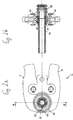
- FIG. 10 shows a cross-sectional view of the arrangement from FIG Fig. 1a a fitting 18, a sleeve 14 and a pipe 16 before a permanent connection between these three workpieces 14, 16, 18 is established.
- the inner contours of the pressing jaws 10 have two mutually facing sliding surfaces 22 which are inclined relative to the receiving area axis 20.
- Both sliding surfaces 22 are designed as cone segments in this example.
- other shapes are also conceivable.
- the angle of inclination of the sliding surfaces 22 can be freely selected.
- the angle of inclination of the sliding surfaces 22 relative to the receiving area axis 20 is constant at approximately 45 °.
- deviations from this value for example up to 35 ° or 55 ° or possibly more, are also possible.
- the sliding surfaces 22 can be designed to promote sliding, for example by means of a coating.
- the fitting 18 has a recess 24 with beveled side walls in the center of its base body.
- the angle of inclination of the side walls is advantageously adapted to the angle of inclination of the sliding surfaces 22 on the pressing jaws 10.
- the sleeve 14 has a bevel 26 on its flange-like projection, which is also at the angle of inclination the sliding surfaces 22, so in this example about 45 ° is adapted. In this way, the pressing process can in particular be stabilized. Before the pressing process, the sliding surfaces 22 are in contact with the aforementioned workpiece surfaces, for example the bevel 26 of the sleeve 14 or the side wall of the recess 24 of the fitting 18.
- Fig. 2a shows the state of the pressing tool 2 and the workpieces 14, 16, 18 after the pressing process in a side view.
- the pivot elements 4 are pivoted inward, so that the abutment surfaces 28 of the pressing jaws 10 rest against one another.
- Figure 2b issues the order Fig. 2a in a cross-sectional view.
- the exerted force was at least partially transmitted via the abutting sliding surfaces 22 and workpiece surfaces from the pressing tool 2 to the workpieces, in this example the sleeve 14 and the fitting 18, and thereby deflected the axial direction.
- the sleeve 14 and the pipe 16 connected to the sleeve 14 and the fitting 18 are moved towards one another, or in other words, are pressed together or pressed together.
- a locking projection arranged on the outer peripheral surface of the sleeve 14 engages in a locking groove arranged on the inner peripheral surface of the outer body of the fitting 18, so that an axial removal of the pipe end 16 encompassed by the sleeve 14 from the fitting 18 is not possible.
- the permanent connection is thus established.
- An axial movement of the pipe 16 out of the fitting 18 is prevented by the latching.
- the support body of the fitting 18 was at least partially molded into the inner circumferential surface of the pipe 16 during the pressing process and thus seals the connection between the pipe 16 and the fitting 18, for example, against fluids (not shown) carried under pressure in the pipe 16.
- a pressing tool 2 which, despite the radial initial movement of the pressing jaws 10, carries out pressing in the axial direction, takes up little assembly space and, in particular, offers improved handiness.
- Fig. 3 shows in a cross-sectional view an arrangement of a pipe 16, a fitting 18 having a support body, the support body engaging in the pipe 16, a transmission element 30 arranged on the pipe outer circumferential surface, which has a wedge shape in cross section and an opening 32 at the wider end of the wedge having visual control of the pressing state, and a sliding sleeve 34 resting on the outside of the transmission element 30, which is also approximately wedge-shaped in cross section, but has a flange-like projection 36 at the wider end.
- the flange-like projection 36 of the sliding sleeve 34 has a bevel 38, the surface of which is provided for interaction with one of the sliding surfaces 22 of the pressing jaws 10 shown schematically in this example.
- the sliding sleeve 34 also includes an opening for visual control of the pressing state of the workpieces 16, 18, 30 and 34.
- the fitting 18 has a recess 24 with an inclined wall surface on its base body, the inclination of the inclined wall surface on the inner contour of the pressing jaws 10 is adapted.
- the pressing jaws 10 comprise two mutually facing sliding surfaces 22 which are designed as cone segments and have an angle of inclination relative to the receiving area axis 20 of approximately 60 °. By choosing this slightly higher angle, the stability of the pressing process in particular can be improved.
- the sliding surfaces 22 of the pressing jaws 10 interact with the inclined wall surfaces on the recess 24 of the fitting 18 and with the bevel 38 of the flange-like projection 36 of the sliding sleeve 34 transmitted to the sliding sleeve 34 and the fitting 18, so that the fitting 18, the sliding sleeve 34 and thus also the transmission element 30 are pushed together in the axial direction.
- the wedge-shaped design of the sliding sleeve 34 and the transmission element 30 and their abutment have the effect that the pressing forces are transmitted to the outer circumferential surface of the pipe during the pressing process and are at least partially deflected again in the radially inward direction.
- the pipe 16 is pressed with the support body of the fitting 18, the material of the pipe 16 being molded in particular into recesses 40 arranged on the outer circumferential surface of the support body, so that axial movement is prevented after the pressing process has ended. In this way, too, a permanent, non-detachable connection between a pipe 16 and a fitting 18 can be created.
Landscapes
- Engineering & Computer Science (AREA)
- Mechanical Engineering (AREA)
- Press Drives And Press Lines (AREA)
- Shaping Metal By Deep-Drawing, Or The Like (AREA)
- Automatic Assembly (AREA)
- Hand Tools For Fitting Together And Separating, Or Other Hand Tools (AREA)
- Non-Disconnectible Joints And Screw-Threaded Joints (AREA)
Description
Die Erfindung betrifft ein Verfahren zum unlösbaren Verbinden von Werkstücken unter Einsatz eines Presswerkzeugs. Dieses Verfahren kann mit einem Presswerkzeug zum unlösbaren Verbinden von Werkstücken mit zwei je eine Pressbacke aufweisenden Schwenkelementen und mit mindestens einer Drehachse, an welcher die Schwenkelemente angelenkt sind, wobei die Innenkonturen der einander gegenüberliegenden Pressbacken einen Aufnahmebereich bilden, durchgeführt werden. Weiterhin wird ein Aufsatz für ein Presswerkzeug mit zwei Pressbacken, wobei jede Pressbacke eine Innenkontur aufweist und wobei die einander gegenüberliegenden Innenkonturen der Pressbacken einen Aufnahmebereich bilden, beschrieben.The invention relates to a method for the permanent connection of workpieces using a pressing tool. This method can be carried out with a pressing tool for permanent connection of workpieces with two swivel elements each having a press jaw and with at least one axis of rotation to which the swivel elements are articulated, the inner contours of the opposing press jaws forming a receiving area. Furthermore, an attachment for a pressing tool with two pressing jaws is described, each pressing jaw having an inner contour and the opposing inner contours of the pressing jaws forming a receiving area.
Presswerkzeuge, Aufsätze für Presswerkzeuge und Verfahren der eingangs genannten Art sind aus dem Stand der Technik, beispielsweise aus dem Trinkwasser- oder Heizungsinstallationsbereich bereits bekannt. Vorzugsweise werden die Werkzeuge und die Verfahren verwendet, um Werkstücke wie Fittings, Rohre, Muffen oder ähnliches radial zu verpressen. Radial verpressen bedeutet dabei im Wesentlichen, mittels einer zangenartigen Schließbewegung zweier Pressbacken aufweisender Schwenkelemente zwei zumindest teilweise in Überlappung angeordnete Werkstücke umzuformen und damit unlösbar miteinander zu verbinden.Pressing tools, attachments for pressing tools and methods of the type mentioned at the beginning are already known from the prior art, for example from the areas of drinking water or heating installations. The tools and the methods are preferably used to radially press workpieces such as fittings, pipes, sleeves or the like. Radial pressing essentially means, by means of a pincer-like closing movement of two swivel elements having pressing jaws, reshaping two workpieces that are at least partially arranged in an overlap and thus connecting them to one another in a permanent manner.
Diese Vorgehensweise kann jedoch nachteilig sein. Mit für diesen Zweck vorgesehenen Presswerkzeugen und Verfahren ist beispielsweise die Ausübung einer allseitig homogenen Presskraft auf die zu verpressenden Werkstücke deutlich erschwert. Vorzugsweise haben Rohre und Fittings vor dem Pressvorgang eine rotationssymmetrische und weitgehend runde Form. Nach dem Pressvorgang kann diese Symmetrie auf Grund inhomogen wirkender Presskräfte an der Verbindungsstelle zwischen Rohr und Fitting jedoch gestört sein, was einerseits den optischen Eindruck als auch die Funktionalität der Verbindung beeinträchtigen kann.However, this approach can be disadvantageous. With pressing tools and methods provided for this purpose, for example, the exertion of a pressing force that is homogeneous on all sides on the workpieces to be pressed is significantly more difficult. Pipes and fittings preferably have a rotationally symmetrical and largely round shape before the pressing process. After the pressing process, however, this symmetry can be disturbed due to inhomogeneous pressing forces at the connection point between pipe and fitting, which on the one hand can impair the visual impression and the functionality of the connection.
Weiterhin können die Werkstoffe, insbesondere Kunststoffe oder Metalle der bei dem Pressvorgang beanspruchten Werkstücke ein gegen die Presskräfte gerichtetes Beharrungsvermögen aufweisen. Dieses Beharrungsvermögen kann in Form von Rückstellkräften dazu führen, dass das bei dem Pressvorgang umgeformte Material zumindest teilweise den Ausgangszustand bzw. das Ausgangsgefüge der Werkstücke wiederherzustellen bestrebt ist. Dies erfordert von dem Anwender eines radial einwärtig wirkenden Pressverfahrens bzw. Presswerkzeugs, dass er die radial einwärtig auszuübenden Presskräfte erhöhen muss, um das gewünschte Pressergebnis zu erhalten. Dies stellt jedoch eine über das eigentliche Maß hinausgehende und deshalb grundsätzlich unerwünschte Inanspruchnahme der Werkstoffe der zu verpressenden Werkstücke dar.Furthermore, the materials, in particular plastics or metals, of the workpieces stressed during the pressing process can have an inertia directed against the pressing forces. This inertia, in the form of restoring forces, can lead to the fact that the material formed during the pressing process at least partially strives to restore the initial state or the initial structure of the workpieces. This requires the user of a radially inwardly acting pressing method or pressing tool that he must increase the pressing forces to be exerted radially inwardly in order to obtain the desired pressing result. However, this represents a use of the materials of the workpieces to be pressed that goes beyond the actual extent and is therefore fundamentally undesirable.
Beispielsweise ist aus der
Aus der
Aus der
Aus der
Die zuvor genannten Probleme können insbesondere mittels einer axialen Verpressungstechnik gelöst bzw. zumindest abgemildert werden. Eine homogene Kraftausübung ist bei einem axialen Pressverfahren deutlich einfacher zu gewährleisten. Die Rückstelleigenschaften der zu verformenden Werkstoffe wirken zwar grundsätzlich auch in axialer Richtung, allerdings können die Auswirkungen einer erhöhten Beanspruchung des Materials wegen der üblicherweise im Vergleich zur radialen Ausdehnung langen axialen Ausdehnung der Werkstücke gering gehalten werden. Nachteilig an axial wirkenden Presswerkzeugen ist jedoch, dass sie einen weiten Montageraum einnehmen und ein hohes Gewicht aufweisen. Die Benutzung solcher Werkzeuge bzw. die Anwendung derartiger Verfahren ist dem Installateur damit erschwert.The aforementioned problems can in particular be solved or at least alleviated by means of an axial compression technique. A homogeneous application of force is much easier to ensure with an axial pressing process. The restoring properties of the materials to be deformed basically also act in the axial direction, but the effects of increased stress on the material can be kept low because of the long axial expansion of the workpieces compared to the radial expansion. However, the disadvantage of axially acting pressing tools is that they take up a large assembly space and are very heavy. The use of such tools or the application of such methods is thus made more difficult for the installer.
Der vorliegenden Erfindung liegt daher das technische Problem zu Grunde, ein alternatives Verfahren anzugeben, mit welchem eine unlösbare Verbindung zwischen Werkstücken durch axiales Verpressen geschaffen werden kann.The present invention is therefore based on the technical problem of specifying an alternative method with which a permanent connection between workpieces can be created by axial pressing.
Gemäß der vorliegenden Erfindung wird das technische Problem durch ein Verfahren gemäß dem Patentanspruch 1 gelöst.According to the present invention, the technical problem is solved by a method according to claim 1.
Vorzugsweise liegt der Gleitfläche eine entsprechend angepasste Werkstückfläche gegenüber. Dadurch wird insbesondere eine größere Anlagefläche zwischen Gleitfläche und Werkstückfläche geschaffen. Auf diese Weise kann beispielsweise die Stabilität des Pressvorgangs erhöht werden.A correspondingly adapted workpiece surface is preferably located opposite the sliding surface. In particular, this creates a larger contact surface between the sliding surface and the workpiece surface. In this way, for example, the stability of the pressing process can be increased.
Hinsichtlich weiterer Vorteile des erfindungsgemäßen Verfahrens wird auf die Unteransprüche bzw. auf die nachfolgenden Ausführungen zu einem Presswerkzeug bzw. zu einem geeigneten Aufsatz für Presswerkzeuge verwiesen.With regard to further advantages of the method according to the invention, reference is made to the subclaims or to the following statements on a pressing tool or on a suitable attachment for pressing tools.
Das zuvor erläuterte Verfahren kann mit einem Presswerkzeug zum unlösbaren Verbinden von Werkstücken mit zwei je eine Pressbacke aufweisenden Schwenkelementen und mit mindestens einer Drehachse, an welcher die Schwenkelemente angelenkt sind, wobei die Innenkonturen der einander gegenüberliegenden Pressbacken einen Aufnahmebereich bilden, durchgeführt werden, wobei die Innenkonturen mindestens eine gegen die Aufnahmebereichsachse geneigte Gleitfläche aufweisen.The method explained above can be carried out with a pressing tool for the permanent connection of workpieces with two swivel elements each having a press jaw and with at least one axis of rotation to which the swivel elements are articulated, the inner contours of the opposing press jaws forming a receiving area, the inner contours have at least one sliding surface inclined with respect to the receiving area axis.
Die Aufnahmebereichsachse verläuft in etwa senkrecht zu der zwischen den Innenkonturen der Pressbacken gelegenen Fläche und entspricht im Wesentlichen der Achse eines zum Zwecke des Verpressens in den Aufnahmebereich einführbaren Werkstücks, beispielsweise eines Rohrs oder Fittings.The receiving area axis runs approximately perpendicular to the surface located between the inner contours of the pressing jaws and essentially corresponds to the axis of a workpiece, for example a pipe or fitting, that can be inserted into the receiving area for the purpose of pressing.
Durch die gegen die Aufnahmebereichsachse geneigte Gleitfläche kann die Dynamik einer radial einwärts ausgeführten Bewegung zumindest teilweise in eine in axiale Richtung verlaufende Presskraft umgewandelt werden. Beim Pressvorgang werden die Schwenkelemente und insbesondere die Pressbacken um die Drehachse aufeinander zu bewegt, während die zu verpressenden Werkstücke in dem Aufnahmebereich zwischen den Pressbacken angeordnet sind. Die Innenkonturen der Pressbacken werden an an den zu verpressenden Werkstücken angeordneten Flächen in Anlage gebracht. Durch die Fortsetzung der radial einwärtigen Bewegung wird der zwischen den Werkstücken und den Innenkonturen verbleibende Bereich verengt. Die in Anlage zu den Werkstücken liegenden Gleitflächen wirken damit als Kraftübertragungs- und Kraftumlenkungsflächen, denn die Gleitfläche und die Fläche an dem Werkstück gleiten übereinander hinweg, während das Werkstück in Bewegung versetzt wird. Auf diese Weise kann, obwohl von einer radial einwärtigen Bewegung ausgehend, eine Relativbewegung zwischen den zu verpressenden Werkstücken in axialer Richtung erzeugt und zur Verpressung benutzt werden.Due to the sliding surface inclined with respect to the receiving area axis, the dynamics of a radially inward movement can at least partially be converted into a pressing force extending in the axial direction. During the pressing process, the swivel elements and in particular the pressing jaws are moved towards one another about the axis of rotation, while the workpieces to be pressed are arranged in the receiving area between the pressing jaws. The inner contours of the pressing jaws are brought into contact with surfaces arranged on the workpieces to be pressed. By continuing the radially inward movement, the area remaining between the workpieces and the inner contours is narrowed. The sliding surfaces in contact with the workpieces thus act as force transmission and force deflection surfaces, because the sliding surface and the surface on the workpiece slide over one another while the workpiece is set in motion. In this way, although starting from a radially inward movement, a relative movement between the workpieces to be pressed can be generated in the axial direction and used for pressing.
Im Ergebnis kann ein Presswerkzeug zur Verfügung gestellt werden, welches eine Verpressung in axialer Richtung durchführt, trotzdem wenig Montageraum in Anspruch nimmt und, beispielsweise durch eine geringere axiale Ausdehnung Gewichtsvorteile bietet.As a result, a pressing tool can be made available which carries out pressing in the axial direction, yet takes up little assembly space and offers weight advantages, for example due to a smaller axial expansion.
Es ist möglich, die Innenkontur jeder Pressbacke mit genau einer Gleitfläche zu versehen. In diesem Fall jedoch weist die Innenkontur bevorzugter Weise auch einen als Widerlager wirkenden Vorsprung auf, welcher der Gleitfläche gegenüber auf der anderen Seite der Innenkontur der Pressbacke angeordnet ist. Vorzugsweise kann dieser Vorsprung einen Abschnitt eines zu verpressenden Werkstücks, insbesondere des Werkstücks, welches nicht mit der Gleitfläche in Kontakt ist, hintergreifen und somit den zur axialen Verpressung notwendigen Gegendruck aufbauen. Eine Kraftumlenkung von einer radial einwärtigen in eine axiale Richtung wird durch den Vorsprung jedoch nicht bewirkt.It is possible to provide the inner contour of each press jaw with exactly one sliding surface. In this case, however, the inner contour preferably also has a projection which acts as an abutment and which is arranged opposite the sliding surface on the other side of the inner contour of the press jaw. This projection can preferably engage behind a section of a workpiece to be pressed, in particular the workpiece which is not in contact with the sliding surface, and thus build up the counterpressure necessary for the axial pressing. A force deflection from a radially inward to an axial direction is not brought about by the projection.
Es ist aber auch möglich, zwei gegen die Aufnahmebereichsachse geneigte, einander zugewandte Gleitflächen vorzusehen. Auf diese Weise kann die umgelenkte und zur axialen Verpressung aufgewendete Kraft erhöht werden. Bei symmetrischer Ausführung der beiden Gleitflächen und entsprechenden Interaktionsflächen an den Werkstücken wird die umgelenkte Presskraft beispielsweise verdoppelt. Es sei aber darauf hingewiesen, dass die Ausgestaltung der beiden Gleitflächen einander nicht entsprechen oder symmetrisch sein muss, sondern auch unterschiedlich ausgeführt werden kann, wenn es für die Anwendung zweckdienlich ist.However, it is also possible to provide two sliding surfaces which are inclined towards the receiving area axis and facing one another. In this way, the deflected force used for the axial compression can be increased. With a symmetrical design of the two sliding surfaces and corresponding interaction surfaces on the workpieces, the deflected pressing force is doubled, for example. It should be noted, however, that the design of the two sliding surfaces does not have to correspond to one another or be symmetrical, but can also be designed differently if it is appropriate for the application.
Besonders vorteilhaft ist es, wenn mindestens eine Gleitfläche als Kegelsegment ausgebildet ist. Auf diese Weise wird insbesondere die Herstellung der Innenkonturen der Pressbacken und gegebenenfalls die Herstellung von Werkstücken mit auf diese Pressbacken angepassten Interaktionsflächen, welche für die zuvor beschriebene Art des Verpressens vorgesehen sind, vereinfacht. Dadurch kann ein hohes Maß an Kompatibilität zwischen den zuvor beschriebenen Presswerkzeugen und den zur Verpressung vorgesehenen Werkstücken wie Rohren, Fittings und ähnlichem erreicht werden.It is particularly advantageous if at least one sliding surface is designed as a conical segment. In this way, in particular, the production of the inner contours of the press jaws and, if necessary, the production of workpieces with interaction surfaces adapted to these press jaws, which are provided for the type of pressing described above, are simplified. As a result, a high degree of compatibility can be achieved between the previously described pressing tools and the workpieces intended for pressing, such as pipes, fittings and the like.
Vorzugsweise liegt der Neigungswinkel der Gleitfläche relativ zur Aufnahmebereichsachse zwischen 35° und 55°, insbesondere bei 45°. Der Neigungswinkel bestimmt im Wesentlichen die Wegstrecke der radial einwärtigen Bewegung, die zurückzulegen ist, um eine axiale Bewegung über eine bestimmte Wegstrecke zu bewirken. Je flacher der Neigungswinkel ist, desto weiter muss die Innenkontur der Pressbacke in axialer Richtung ausgreifen, um ein bestimmtes Pressergebnis zu erzielen, wohingegen die radiale Ausdehnung der Pressbacke recht schmal bemessen werden kann. Ein Winkel von beispielsweise 35° bewirkt somit eine aus der radialen Bewegung heraus recht effiziente Kraftumlenkung, wohingegen ein Winkel von 55° zwar einen längeren radialen Weg zur Folge hat, dafür aber eine höhere Stabilität während der Verpressung gewährleistet. Der Winkel von 45° ist wiederum insbesondere geeignet, zwischen den beiden Effekten einen Ausgleich zu schaffen. Darüber hinaus können die äußeren Abmessungen der Pressbacken auf diese Weise sowohl in radialer als auch in axialer Richtung optimiert werden.The angle of inclination of the sliding surface relative to the receiving area axis is preferably between 35 ° and 55 °, in particular 45 °. The angle of inclination essentially determines the distance of the radially inward movement that has to be covered in order to bring about an axial movement over a certain distance. The flatter the angle of inclination, the further the inner contour of the press jaw has to extend in the axial direction in order to achieve a specific pressing result, whereas the radial extension of the press jaw can be made quite narrow. An angle of 35 °, for example, results in a very efficient deflection of force from the radial movement, whereas an angle of 55 ° results in a longer radial path, but ensures greater stability during the pressing. Of the An angle of 45 ° is in turn particularly suitable for creating a balance between the two effects. In addition, the outer dimensions of the pressing jaws can be optimized in this way both in the radial and in the axial direction.
Es ist weiterhin besonders bevorzugt, dass die Gleitfläche gleitfördernd ausgebildet ist. Auf diese Weise kann die Trägheit, welche die zu verpressenden Werkstücke einer axialen Ausweichbewegung entgegensetzen, zumindest verringert werden, so dass der Pressvorgang leichter auszuführen ist. Die Gleitfläche gleitfördernd auszubilden, kann auf unterschiedliche Weise geschehen. Es ist möglich, den Abschnitt der Innenkontur der Pressbacke, welcher die Gleitfläche umfasst, mit dem Rest der Pressbacke zweiteilig auszubilden, und die Gleitfläche aus einem Material wie Polytetrafluoroethylen oder ähnlichem zu fertigen. Es ist allerdings auch möglich, das Gleitvermögen mittels einer gleitfördernden Beschichtung der Gleitfläche zu erhöhen, beispielsweise mit einer Gleitlackbeschichtung. Ebenso ist es möglich, durch eine Glättung der Gleitfläche, bspw. durch Polieren der Gleitfläche diese gleitfördernd auszubilden.It is also particularly preferred that the sliding surface is designed to promote sliding. In this way, the inertia which the workpieces to be pressed oppose an axial evasive movement can at least be reduced, so that the pressing process can be carried out more easily. Forming the sliding surface to promote sliding can be done in different ways. It is possible to form the section of the inner contour of the press jaw, which includes the sliding surface, in two parts with the rest of the press jaw, and to manufacture the sliding surface from a material such as polytetrafluoroethylene or the like. However, it is also possible to increase the sliding property by means of a sliding-promoting coating of the sliding surface, for example with a sliding varnish coating. It is also possible, by smoothing the sliding surface, for example by polishing the sliding surface, to make it slide-promoting.
Das Presswerkzeug kann einen Aufsatz für ein Presswerkzeug mit zwei Pressbacken aufweisen, wobei jede Pressbacke eine Innenkontur aufweist und wobei die einander gegenüberliegenden Innenkonturen der Pressbacken einen Aufnahmebereich bilden undwobei die Innenkonturen mindestens eine gegen die Aufnahmebereichsachse geneigte Gleitfläche aufweisen.The pressing tool can have an attachment for a pressing tool with two pressing jaws, each pressing jaw having an inner contour and the opposing inner contours of the pressing jaws forming a receiving area and the inner contours having at least one sliding surface inclined towards the receiving area axis.
Auf diese Weise können ursprünglich für die radiale Verpressung vorgesehene Presswerkzeuge auf einfache Weise für eine axiale Verpressung tauglich gemacht werden. Die Neufertigung an die geänderten Anforderungen entsprechend angepasster Schwenkelemente ist somit nicht mehr erforderlich, woraus sich insbesondere ökonomische Vorteile ergeben.In this way, pressing tools originally intended for radial pressing can be made suitable for axial pressing in a simple manner. The new production of swivel elements adapted to the changed requirements is therefore no longer necessary, which results in particular economic advantages.
Im Folgenden wird die Erfindung an Hand von in einer Zeichnung dargestellten Ausführungsbeispielen näher erläutert. In der Zeichnung zeigen:
- Fig. 1a,b
- ein Ausführungsbeispiel des Presswerkzeugs vor dem Pressvorgang in zwei unterschiedlichen Ansichten,
- Fig. 2a,b
- das Ausführungsbeispiel des Presswerkzeugs aus den
Fig. 1a, b nach dem Pressvorgang in zwei unterschiedlichen Ansichten und - Fig. 3
- ein weiteres Ausführungsbeispiel der Anwendung eines Presswerkzeugs.
- Fig. 1a, b
- an embodiment of the pressing tool before the pressing process in two different views,
- Fig. 2a, b
- the embodiment of the pressing tool from the
Fig. 1a, b after the pressing process in two different views and - Fig. 3
- another embodiment of the use of a pressing tool.
Im Folgenden wird der Pressvorgang beschrieben. Selbstverständlich ist das Presswerkzeug 2 oder das erfindungsgemäße Verfahren nicht auf die Verwendung von den hier beispielhaft dargestellten Rohren 16, Hülsen 14 oder Fittings 18 beschränkt.The pressing process is described below. Of course, the pressing tool 2 or the method according to the invention is not limited to the use of the
Die hier beispielhaft gezeigten Schwenkelemente 4 können auch mit abnehmbaren Pressbacken 10 versehen sein. Auf diese Weise können mittels eines Aufsatzes für ein Presswerkzeug 2 bereits gefertigte Presswerkzeuge 2, welche ursprünglich für eine radiale Verpressung vorgesehen waren, auch für eine axiale Verpressung tauglich gemacht werden.The
Die Innenkonturen der Pressbacken 10 weisen in diesem Beispiel zwei gegen die Aufnahmebereichsachse 20 geneigte, einander zugewandte Gleitflächen 22 auf. Beide Gleitflächen 22 sind in diesem Beispiel als Kegelsegmente ausgebildet. Andere Formen sind jedoch auch denkbar. Insbesondere kann der Neigungswinkel der Gleitflächen 22 frei gewählt werden. Der Neigungswinkel der Gleitflächen 22 relativ zur Aufnahmebereichsachse 20 liegt in diesem Beispiel jedoch konstant bei etwa 45°. Abweichungen von diesem Wert, beispielsweise bis 35° oder 55° oder gegebenenfalls darüber hinaus sind jedoch ebenfalls möglich. In diesem Ausführungsbeispiel nicht dargestellt können die Gleitflächen 22, beispielsweise mittels einer Beschichtung gleitfördernd ausgebildet sein.In this example, the inner contours of the
Das Fitting 18 weist mittig an seinem Grundkörper eine Ausnehmung 24 mit abgeschrägten Seitenwänden auf. Der Neigungswinkel der Seitenwände ist in diesem Beispiel vorteilhafterweise auf den Neigungswinkel der Gleitflächen 22 an den Pressbacken 10 angepasst. Ferner weist die Hülse 14 an ihrem flanschartigen Vorsprung eine Fase 26 auf, welche ebenfalls an den Neigungswinkel der Gleitflächen 22, also in diesem Beispiel etwa 45° angepasst ist. Auf diese Weise kann der Pressvorgang insbesondere stabilisiert werden. Vor dem Pressvorgang sind die Gleitflächen 22 in Anlage mit den zuvor genannten Werkstückflächen, beispielsweise der Fase 26 der Hülse 14 oder der Seitenwand der Ausnehmung 24 des Fittings 18.The fitting 18 has a
Nach dem axialen Pressvorgang ist ein an der Außenumfangsfläche der Hülse 14 angeordneter Rastvorsprung in einer an der Innenumfangsfläche des Außenkörpers des Fittings 18 angeordneten Rastnut eingerastet, so dass ein axiales Entfernen des von der Hülse 14 umgriffenen Rohrendes 16 aus dem Fitting 18 nicht möglich ist.After the axial pressing process, a locking projection arranged on the outer peripheral surface of the
Die unlösbare Verbindung ist damit hergestellt. Eine axiale Bewegung des Rohrs 16 aus dem Fitting 18 heraus wird durch die Verrastung verhindert. Der Stützkörper des Fittings 18 wurde während des Pressvorgangs in die Innenumfangsfläche des Rohrs 16 zumindest teilweise eingeformt und dichtet somit die Verbindung zwischen Rohr 16 und Fitting 18 beispielsweise gegenüber in dem Rohr 16 unter Druckbeaufschlagung geführten Fluiden (nicht dargestellt) ab.The permanent connection is thus established. An axial movement of the
Im Ergebnis ist ein Presswerkzeug 2 zum Einsatz gekommen, welches trotz radialer Ausgangsbewegung der Pressbacken 10 eine Verpressung in axialer Richtung durchführt, wenig Montageraum in Anspruch nimmt und insbesondere eine verbesserte Handlichkeit bietet.As a result, a pressing tool 2 has been used which, despite the radial initial movement of the
Die Pressbacken 10 umfassen in diesem Beispiel zwei einander zugewandte Gleitflächen 22, welche als Kegelsegmente ausgebildet sind, und einen Neigungswinkel relativ gegen die Aufnahmebereichsachse 20 von etwa 60° aufweisen. Durch die Wahl dieses etwas höheren Winkels kann insbesondere die Stabilität des Pressvorgangs verbessert werden.In this example, the
Während des Pressvorgangs interagieren die Gleitflächen 22 der Pressbacken 10 mit den schrägen Wandflächen an der Ausnehmung 24 des Fittings 18 und mit der Fase 38 des flanschartigen Vorsprungs 36 der Gleithülse 34. Die durch eine radial einwärtige Bewegung der Pressbacken 10 bewirkte Dynamik wird über die Gleitflächen 22 an die Gleithülse 34 und das Fitting 18 übertragen, so dass das Fitting 18, die Gleithülse 34 und damit auch das Übertragungselement 30 in axialer Richtung zusammen geschoben werden. Die keilförmige Ausgestaltung der Gleithülse 34 und des Übertragungselements 30 sowie deren Anlage bewirken, dass die Presskräfte während des Pressvorgangs auf die Rohraußenumfangsfläche übertragen und zumindest teilweise wieder in radial einwärtige Richtung umgelenkt werden. Dadurch wird das Rohr 16 mit dem Stützkörper des Fittings 18 verpresst, wobei Material des Rohrs 16 insbesondere in an der Außenumfangsfläche des Stützkörpers angeordnete Vertiefungen 40 eingeformt wird, so dass eine axiale Bewegung nach der Beendigung des Pressvorgangs verhindert wird. Auch auf diese Weise kann somit eine dauerhafte unlösbare Verbindung zwischen einem Rohr 16 und einem Fitting 18 geschaffen werden.During the pressing process, the sliding
Claims (3)
- A method for the permanent connection of workpieces from the drinking water sector or heating installation sector such as fittings, pipes, bushings or the like by using a pressing tool,- in which the pressing tool is actuated radially inward,- in which at least one slide face arranged on the pressing tool and inclined relative to the workpiece axis and one workpiece face are brought into abutment to one another,- in which the radially inwardly exerted pressing force is transmitted from the slide face onto the workpiece face and is at least partially deflected in axial direction, wherein the slide face and the workpiece face are sliding over each other, and- the workpieces are pressed together in axial direction.
- The method according to claim 1,
in which the slide face is opposed by a correspondingly adapted workpiece face. - The method according to claim 1 or 2,
in which the deflection is effected through an angle between 35° and 55°, in particular 45°.
Priority Applications (4)
| Application Number | Priority Date | Filing Date | Title |
|---|---|---|---|
| PL09713367.2T PL2265415T6 (en) | 2008-02-19 | 2009-01-30 | Method for the permanent connection of workpieces |
| DK13158294.2T DK2602062T3 (en) | 2008-02-19 | 2009-01-30 | Press tool and press tool set |
| PL13158294T PL2602062T3 (en) | 2008-02-19 | 2009-01-30 | Compression tool and attachment for a compression tool |
| EP13158294.2A EP2602062B1 (en) | 2008-02-19 | 2009-01-30 | Compression tool and attachment for a compression tool |
Applications Claiming Priority (2)
| Application Number | Priority Date | Filing Date | Title |
|---|---|---|---|
| DE102008010083A DE102008010083A1 (en) | 2008-02-19 | 2008-02-19 | Process for the permanent joining of workpieces, pressing tool and attachment for a pressing tool |
| PCT/EP2009/051062 WO2009103605A1 (en) | 2008-02-19 | 2009-01-30 | Method for the permanent connection of workpieces, compression tool, and attachment for a compression tool |
Related Child Applications (2)
| Application Number | Title | Priority Date | Filing Date |
|---|---|---|---|
| EP13158294.2A Division-Into EP2602062B1 (en) | 2008-02-19 | 2009-01-30 | Compression tool and attachment for a compression tool |
| EP13158294.2 Division-Into | 2013-03-08 |
Publications (3)
| Publication Number | Publication Date |
|---|---|
| EP2265415A1 EP2265415A1 (en) | 2010-12-29 |
| EP2265415B1 EP2265415B1 (en) | 2013-08-28 |
| EP2265415B2 true EP2265415B2 (en) | 2021-03-10 |
Family
ID=40613016
Family Applications (2)
| Application Number | Title | Priority Date | Filing Date |
|---|---|---|---|
| EP09713367.2A Active EP2265415B2 (en) | 2008-02-19 | 2009-01-30 | Method for the permanent connection of workpieces |
| EP13158294.2A Revoked EP2602062B1 (en) | 2008-02-19 | 2009-01-30 | Compression tool and attachment for a compression tool |
Family Applications After (1)
| Application Number | Title | Priority Date | Filing Date |
|---|---|---|---|
| EP13158294.2A Revoked EP2602062B1 (en) | 2008-02-19 | 2009-01-30 | Compression tool and attachment for a compression tool |
Country Status (13)
| Country | Link |
|---|---|
| US (1) | US8567034B2 (en) |
| EP (2) | EP2265415B2 (en) |
| CN (1) | CN101977735B (en) |
| AU (1) | AU2009216886B2 (en) |
| CA (1) | CA2716178C (en) |
| DE (2) | DE102008010083A1 (en) |
| DK (2) | DK2602062T3 (en) |
| ES (2) | ES2449384T3 (en) |
| MX (1) | MX2010009167A (en) |
| PL (2) | PL2602062T3 (en) |
| PT (2) | PT2265415E (en) |
| RU (1) | RU2446934C1 (en) |
| WO (1) | WO2009103605A1 (en) |
Families Citing this family (9)
| Publication number | Priority date | Publication date | Assignee | Title |
|---|---|---|---|---|
| CN102819342A (en) * | 2011-06-10 | 2012-12-12 | 深圳富泰宏精密工业有限公司 | Installation mechanism of touch panel |
| DE102012105655A1 (en) | 2012-06-28 | 2014-01-02 | Viega Gmbh & Co. Kg | Press jaw and method for producing a permanent pipe connection and system of a pressing jaw and a fitting |
| DE102014002191A1 (en) * | 2014-02-11 | 2015-08-13 | Spieth-Maschinenelemente Gmbh & Co. Kg | machine element |
| CN107756867B (en) * | 2017-11-27 | 2023-12-29 | 吕言 | An intelligent control device of a press machine method and press system |
| CN108749106B (en) * | 2018-05-28 | 2024-01-19 | 南通超达装备股份有限公司 | Quick switching device for large-scale interchangeable inserts |
| US11398719B2 (en) | 2019-04-30 | 2022-07-26 | Eaton Intelligent Power Limited | Press fit condulet devices, assemblies systems and methods for electrical raceway fabrication |
| US11996683B2 (en) | 2020-10-19 | 2024-05-28 | Eaton Intelligent Power Limited | Compressible condulet devices, assemblies, systems and methods for electrical raceway fabrication |
| EP4251372B1 (en) | 2020-11-24 | 2025-09-24 | Rothenberger AG | Radial pressing tool |
| EP4457047A1 (en) | 2021-12-31 | 2024-11-06 | Rothenberger AG | Method for producing a radial pressing tool, and radial pressing tool |
Citations (5)
| Publication number | Priority date | Publication date | Assignee | Title |
|---|---|---|---|---|
| US3529855A (en) † | 1966-09-21 | 1970-09-22 | Parker Hannifin Corp | Coupling for tubes |
| DE2725280A1 (en) † | 1977-06-01 | 1978-12-14 | Mannesmann Roehren Werke Ag | Pipe connection system for thin metal pipes - uses compressible sleeve with conical section and ring collars |
| GB2205373A (en) † | 1987-05-23 | 1988-12-07 | Mie Horo Co Ltd | Method of making piping joints and joining tool |
| WO1990012237A1 (en) † | 1989-04-10 | 1990-10-18 | Raychem Corporation | Method of applying axial force between two objects |
| DE19958102C1 (en) † | 1999-12-02 | 2001-02-08 | Selck Gmbh & Co Kg | Pressure-sealed coupling for pipes has a coupling sleeve with inner teeth covered by a pressure ring and end press rings which force the teeth by inner projections against the pipe surface with min pressure |
Family Cites Families (13)
| Publication number | Priority date | Publication date | Assignee | Title |
|---|---|---|---|---|
| CH502545A (en) | 1970-03-13 | 1971-01-31 | Higgs Robert John Ingenieur | Machine for pressing sleeve-shaped parts onto concentric elements with a circular cross-section |
| DE2719882A1 (en) * | 1977-04-29 | 1978-11-02 | Mannesmann Roehren Werke Ag | Coupling for metal transmission pipe - uses metallic sleeve with sealing rings compressed into pipe wall |
| JPH0248092Y2 (en) * | 1987-12-29 | 1990-12-18 | ||
| ATE139017T1 (en) | 1988-05-25 | 1996-06-15 | Nussbaum & Co Ag R | PRESS CONNECTION ARRANGEMENT, FITTING AND METHOD OF MANUFACTURING |
| RU2065120C1 (en) * | 1993-03-19 | 1996-08-10 | Николай Григорьевич Алексеев | Arrangement for connection of pipes |
| EP0858568B1 (en) | 1995-11-04 | 2001-12-12 | Novo-Press GmbH Pressen und Presswerkzeuge & Co. Kg. | Process for connecting a pipe with a press fitting and combination of press fitting, pipe and pressing device |
| IT1290534B1 (en) | 1997-04-07 | 1998-12-04 | Raccorderie Metalliche Spa | PRESS FITTING |
| DE19840668C1 (en) * | 1998-08-26 | 1999-11-25 | Mannesmann Ag | Press fit pipe coupling |
| DE19906957B4 (en) | 1999-02-19 | 2007-07-12 | Qualimed Innovative Medizin-Produkte Gmbh | Inlay for use in crimping a stent and crimping tool |
| DE10144100C1 (en) * | 2001-09-04 | 2003-02-13 | Mapress Gmbh & Co Kg | Pipe compression coupling formation method uses compression tool cooperating with compression fitting attached to pipe end |
| FR2864602B1 (en) * | 2003-12-24 | 2007-07-13 | Comap | CRIMPING JAW |
| RU55976U1 (en) * | 2006-01-25 | 2006-08-27 | ОАО "Татнефть" им. В.Д. Шашина | NIPPLE PIPE TEST |
| CN201154470Y (en) * | 2007-10-17 | 2008-11-26 | 朱功明 | A stamping tool that connects battery holder springs to metal contacts |
-
2008
- 2008-02-19 DE DE102008010083A patent/DE102008010083A1/en not_active Ceased
-
2009
- 2009-01-30 CN CN200980109831.XA patent/CN101977735B/en active Active
- 2009-01-30 ES ES13158294.2T patent/ES2449384T3/en active Active
- 2009-01-30 PT PT97133672T patent/PT2265415E/en unknown
- 2009-01-30 PL PL13158294T patent/PL2602062T3/en unknown
- 2009-01-30 MX MX2010009167A patent/MX2010009167A/en active IP Right Grant
- 2009-01-30 PL PL09713367.2T patent/PL2265415T6/en unknown
- 2009-01-30 US US12/735,865 patent/US8567034B2/en active Active
- 2009-01-30 DK DK13158294.2T patent/DK2602062T3/en active
- 2009-01-30 DK DK09713367.2T patent/DK2265415T4/en active
- 2009-01-30 AU AU2009216886A patent/AU2009216886B2/en active Active
- 2009-01-30 EP EP09713367.2A patent/EP2265415B2/en active Active
- 2009-01-30 EP EP13158294.2A patent/EP2602062B1/en not_active Revoked
- 2009-01-30 CA CA2716178A patent/CA2716178C/en active Active
- 2009-01-30 PT PT131582942T patent/PT2602062E/en unknown
- 2009-01-30 WO PCT/EP2009/051062 patent/WO2009103605A1/en not_active Ceased
- 2009-01-30 DE DE202009018809U patent/DE202009018809U1/en not_active Expired - Lifetime
- 2009-01-30 RU RU2010138613/02A patent/RU2446934C1/en active
- 2009-01-30 ES ES09713367T patent/ES2435533T5/en active Active
Patent Citations (5)
| Publication number | Priority date | Publication date | Assignee | Title |
|---|---|---|---|---|
| US3529855A (en) † | 1966-09-21 | 1970-09-22 | Parker Hannifin Corp | Coupling for tubes |
| DE2725280A1 (en) † | 1977-06-01 | 1978-12-14 | Mannesmann Roehren Werke Ag | Pipe connection system for thin metal pipes - uses compressible sleeve with conical section and ring collars |
| GB2205373A (en) † | 1987-05-23 | 1988-12-07 | Mie Horo Co Ltd | Method of making piping joints and joining tool |
| WO1990012237A1 (en) † | 1989-04-10 | 1990-10-18 | Raychem Corporation | Method of applying axial force between two objects |
| DE19958102C1 (en) † | 1999-12-02 | 2001-02-08 | Selck Gmbh & Co Kg | Pressure-sealed coupling for pipes has a coupling sleeve with inner teeth covered by a pressure ring and end press rings which force the teeth by inner projections against the pipe surface with min pressure |
Also Published As
| Publication number | Publication date |
|---|---|
| EP2602062A1 (en) | 2013-06-12 |
| MX2010009167A (en) | 2010-11-30 |
| US8567034B2 (en) | 2013-10-29 |
| ES2435533T3 (en) | 2013-12-20 |
| US20110016696A1 (en) | 2011-01-27 |
| PL2602062T3 (en) | 2014-05-30 |
| PL2265415T3 (en) | 2014-01-31 |
| ES2435533T5 (en) | 2021-10-28 |
| WO2009103605A1 (en) | 2009-08-27 |
| CN101977735B (en) | 2016-05-25 |
| CA2716178C (en) | 2014-02-25 |
| PL2265415T6 (en) | 2022-07-18 |
| ES2449384T3 (en) | 2014-03-19 |
| EP2265415B1 (en) | 2013-08-28 |
| AU2009216886B2 (en) | 2012-11-01 |
| EP2602062B1 (en) | 2013-12-25 |
| AU2009216886A1 (en) | 2009-08-27 |
| EP2265415A1 (en) | 2010-12-29 |
| PT2265415E (en) | 2013-11-21 |
| PT2602062E (en) | 2014-03-04 |
| DE102008010083A1 (en) | 2009-08-27 |
| RU2446934C1 (en) | 2012-04-10 |
| DE202009018809U1 (en) | 2013-08-13 |
| CA2716178A1 (en) | 2009-08-19 |
| CN101977735A (en) | 2011-02-16 |
| DK2265415T3 (en) | 2013-11-25 |
| DK2265415T4 (en) | 2021-05-31 |
| DK2602062T3 (en) | 2014-03-17 |
Similar Documents
| Publication | Publication Date | Title |
|---|---|---|
| EP2265415B2 (en) | Method for the permanent connection of workpieces | |
| DE102008039446B4 (en) | Arrangement and method for producing a non-detachable workpiece connection | |
| DE69202309T2 (en) | Method of forming excess thickness at the ends of the inner tube of a joint after molding and its uses. | |
| DE2226070C3 (en) | Coupling sleeve for connecting electrical conductors and process for their production | |
| EP2809463B1 (en) | Expansion head for expansion tools, expansion tool comprising said expansion head and use thereof | |
| DE2844475A1 (en) | RADIAL PRESS FOR WORKPIECES WITH CYLINDRICAL OUTER SURFACE WITH SEVERAL PRESS JAWS IN A CIRCLE | |
| DE2505915A1 (en) | DEVICE FOR EXPANSION OF PIPE ENDS | |
| DE2552607A1 (en) | HAND TOOL FOR EXPANSION OF PIPE ENDS | |
| DE3019593C2 (en) | ||
| DE8121384U1 (en) | DETACHABLE PIPE COUPLING AND CARTRIDGE FOR FORMING SUCH PIPE COUPLING | |
| DE3226868A1 (en) | PERMANENTLY TIGHT THREADED PIPE CONNECTION | |
| EP0380970A2 (en) | Pipe connection and process for manufacturing the same | |
| DE2406361A1 (en) | Flanged bushes formed from single blank - is formed in two operations to avoid stressing blank shaped to developed profile | |
| DE2845308A1 (en) | Plastics pipe coupling sleeve - has two collars into which an elastic annular seal with Y-cross=section is firmly fitted | |
| DE2421505A1 (en) | METHOD AND DEVICE FOR ASSEMBLING ELASTIC BUSHINGS | |
| DE3242703A1 (en) | METHOD FOR PRODUCING A COMMUTATOR SEGMENT RING | |
| EP2918354B1 (en) | Pressing attachment for axially pressing workpieces | |
| DE10361004A1 (en) | Receiving part of a fluid plug-in coupling and method for its preparation | |
| CH671083A5 (en) | ||
| DE102009044279B4 (en) | Method for producing a wall connection piece and associated wall connection piece | |
| DE2516656C3 (en) | Method for the tight connection of two components to one another by resistance welding, in particular for the production of a tubular housing of a telescopic vibration damper, primarily for motor vehicles | |
| DE3044291A1 (en) | "METHOD AND DEVICE FOR PERMANENTLY CONNECTING CIRCULAR PARTS, LIKE WAVE PARTS OR THE LIKE. | |
| DE2032132B2 (en) | Method and device for the production of dome-shaped housing halves | |
| DE3634596A1 (en) | METHOD AND DEVICE FOR THE PRODUCTION OF BODY PARTS IN COMPOSITE TECHNOLOGY | |
| DE10356269B3 (en) | Device for sealing the gap between workpiece parts moving relative to each other used in casting and thixoforming methods comprises a sealing element formed on one workpiece part in the form of a spring element |
Legal Events
| Date | Code | Title | Description |
|---|---|---|---|
| PUAI | Public reference made under article 153(3) epc to a published international application that has entered the european phase |
Free format text: ORIGINAL CODE: 0009012 |
|
| 17P | Request for examination filed |
Effective date: 20100818 |
|
| AK | Designated contracting states |
Kind code of ref document: A1 Designated state(s): AT BE BG CH CY CZ DE DK EE ES FI FR GB GR HR HU IE IS IT LI LT LU LV MC MK MT NL NO PL PT RO SE SI SK TR |
|
| AX | Request for extension of the european patent |
Extension state: AL BA RS |
|
| DAX | Request for extension of the european patent (deleted) | ||
| 17Q | First examination report despatched |
Effective date: 20120423 |
|
| GRAP | Despatch of communication of intention to grant a patent |
Free format text: ORIGINAL CODE: EPIDOSNIGR1 |
|
| INTG | Intention to grant announced |
Effective date: 20130405 |
|
| GRAS | Grant fee paid |
Free format text: ORIGINAL CODE: EPIDOSNIGR3 |
|
| GRAA | (expected) grant |
Free format text: ORIGINAL CODE: 0009210 |
|
| AK | Designated contracting states |
Kind code of ref document: B1 Designated state(s): AT BE BG CH CY CZ DE DK EE ES FI FR GB GR HR HU IE IS IT LI LT LU LV MC MK MT NL NO PL PT RO SE SI SK TR |
|
| REG | Reference to a national code |
Ref country code: GB Ref legal event code: FG4D Free format text: NOT ENGLISH |
|
| REG | Reference to a national code |
Ref country code: CH Ref legal event code: EP |
|
| REG | Reference to a national code |
Ref country code: AT Ref legal event code: REF Ref document number: 629021 Country of ref document: AT Kind code of ref document: T Effective date: 20130915 |
|
| REG | Reference to a national code |
Ref country code: IE Ref legal event code: FG4D Free format text: LANGUAGE OF EP DOCUMENT: GERMAN |
|
| REG | Reference to a national code |
Ref country code: DE Ref legal event code: R096 Ref document number: 502009007881 Country of ref document: DE Effective date: 20131017 |
|
| REG | Reference to a national code |
Ref country code: PT Ref legal event code: SC4A Free format text: AVAILABILITY OF NATIONAL TRANSLATION Effective date: 20131114 |
|
| REG | Reference to a national code |
Ref country code: DK Ref legal event code: T3 Effective date: 20131119 |
|
| REG | Reference to a national code |
Ref country code: CH Ref legal event code: NV Representative=s name: TROESCH SCHEIDEGGER WERNER AG, CH |
|
| REG | Reference to a national code |
Ref country code: SE Ref legal event code: TRGR |
|
| REG | Reference to a national code |
Ref country code: NL Ref legal event code: T3 |
|
| REG | Reference to a national code |
Ref country code: ES Ref legal event code: FG2A Ref document number: 2435533 Country of ref document: ES Kind code of ref document: T3 Effective date: 20131220 |
|
| REG | Reference to a national code |
Ref country code: LT Ref legal event code: MG4D |
|
| PG25 | Lapsed in a contracting state [announced via postgrant information from national office to epo] |
Ref country code: IS Free format text: LAPSE BECAUSE OF FAILURE TO SUBMIT A TRANSLATION OF THE DESCRIPTION OR TO PAY THE FEE WITHIN THE PRESCRIBED TIME-LIMIT Effective date: 20131228 Ref country code: LT Free format text: LAPSE BECAUSE OF FAILURE TO SUBMIT A TRANSLATION OF THE DESCRIPTION OR TO PAY THE FEE WITHIN THE PRESCRIBED TIME-LIMIT Effective date: 20130828 Ref country code: NO Free format text: LAPSE BECAUSE OF FAILURE TO SUBMIT A TRANSLATION OF THE DESCRIPTION OR TO PAY THE FEE WITHIN THE PRESCRIBED TIME-LIMIT Effective date: 20131128 Ref country code: HR Free format text: LAPSE BECAUSE OF FAILURE TO SUBMIT A TRANSLATION OF THE DESCRIPTION OR TO PAY THE FEE WITHIN THE PRESCRIBED TIME-LIMIT Effective date: 20130828 Ref country code: CY Free format text: LAPSE BECAUSE OF FAILURE TO SUBMIT A TRANSLATION OF THE DESCRIPTION OR TO PAY THE FEE WITHIN THE PRESCRIBED TIME-LIMIT Effective date: 20130918 |
|
| REG | Reference to a national code |
Ref country code: PL Ref legal event code: T3 |
|
| PG25 | Lapsed in a contracting state [announced via postgrant information from national office to epo] |
Ref country code: FI Free format text: LAPSE BECAUSE OF FAILURE TO SUBMIT A TRANSLATION OF THE DESCRIPTION OR TO PAY THE FEE WITHIN THE PRESCRIBED TIME-LIMIT Effective date: 20130828 Ref country code: SI Free format text: LAPSE BECAUSE OF FAILURE TO SUBMIT A TRANSLATION OF THE DESCRIPTION OR TO PAY THE FEE WITHIN THE PRESCRIBED TIME-LIMIT Effective date: 20130828 Ref country code: GR Free format text: LAPSE BECAUSE OF FAILURE TO SUBMIT A TRANSLATION OF THE DESCRIPTION OR TO PAY THE FEE WITHIN THE PRESCRIBED TIME-LIMIT Effective date: 20131129 Ref country code: LV Free format text: LAPSE BECAUSE OF FAILURE TO SUBMIT A TRANSLATION OF THE DESCRIPTION OR TO PAY THE FEE WITHIN THE PRESCRIBED TIME-LIMIT Effective date: 20130828 |
|
| REG | Reference to a national code |
Ref country code: SK Ref legal event code: T3 Ref document number: E 15384 Country of ref document: SK |
|
| PG25 | Lapsed in a contracting state [announced via postgrant information from national office to epo] |
Ref country code: CY Free format text: LAPSE BECAUSE OF FAILURE TO SUBMIT A TRANSLATION OF THE DESCRIPTION OR TO PAY THE FEE WITHIN THE PRESCRIBED TIME-LIMIT Effective date: 20130828 |
|
| PG25 | Lapsed in a contracting state [announced via postgrant information from national office to epo] |
Ref country code: RO Free format text: LAPSE BECAUSE OF FAILURE TO SUBMIT A TRANSLATION OF THE DESCRIPTION OR TO PAY THE FEE WITHIN THE PRESCRIBED TIME-LIMIT Effective date: 20130828 Ref country code: EE Free format text: LAPSE BECAUSE OF FAILURE TO SUBMIT A TRANSLATION OF THE DESCRIPTION OR TO PAY THE FEE WITHIN THE PRESCRIBED TIME-LIMIT Effective date: 20130828 |
|
| PLBI | Opposition filed |
Free format text: ORIGINAL CODE: 0009260 |
|
| 26 | Opposition filed |
Opponent name: REMS GMBH & CO KG Effective date: 20140527 |
|
| PLAX | Notice of opposition and request to file observation + time limit sent |
Free format text: ORIGINAL CODE: EPIDOSNOBS2 |
|
| REG | Reference to a national code |
Ref country code: HU Ref legal event code: AG4A Ref document number: E019781 Country of ref document: HU |
|
| REG | Reference to a national code |
Ref country code: DE Ref legal event code: R026 Ref document number: 502009007881 Country of ref document: DE Effective date: 20140527 |
|
| PG25 | Lapsed in a contracting state [announced via postgrant information from national office to epo] |
Ref country code: LU Free format text: LAPSE BECAUSE OF FAILURE TO SUBMIT A TRANSLATION OF THE DESCRIPTION OR TO PAY THE FEE WITHIN THE PRESCRIBED TIME-LIMIT Effective date: 20140130 Ref country code: MC Free format text: LAPSE BECAUSE OF FAILURE TO SUBMIT A TRANSLATION OF THE DESCRIPTION OR TO PAY THE FEE WITHIN THE PRESCRIBED TIME-LIMIT Effective date: 20130828 |
|
| PLAF | Information modified related to communication of a notice of opposition and request to file observations + time limit |
Free format text: ORIGINAL CODE: EPIDOSCOBS2 |
|
| PLBB | Reply of patent proprietor to notice(s) of opposition received |
Free format text: ORIGINAL CODE: EPIDOSNOBS3 |
|
| REG | Reference to a national code |
Ref country code: FR Ref legal event code: PLFP Year of fee payment: 8 |
|
| PG25 | Lapsed in a contracting state [announced via postgrant information from national office to epo] |
Ref country code: MT Free format text: LAPSE BECAUSE OF FAILURE TO SUBMIT A TRANSLATION OF THE DESCRIPTION OR TO PAY THE FEE WITHIN THE PRESCRIBED TIME-LIMIT Effective date: 20130828 |
|
| PG25 | Lapsed in a contracting state [announced via postgrant information from national office to epo] |
Ref country code: BG Free format text: LAPSE BECAUSE OF FAILURE TO SUBMIT A TRANSLATION OF THE DESCRIPTION OR TO PAY THE FEE WITHIN THE PRESCRIBED TIME-LIMIT Effective date: 20130828 |
|
| APAH | Appeal reference modified |
Free format text: ORIGINAL CODE: EPIDOSCREFNO |
|
| APBM | Appeal reference recorded |
Free format text: ORIGINAL CODE: EPIDOSNREFNO |
|
| APBP | Date of receipt of notice of appeal recorded |
Free format text: ORIGINAL CODE: EPIDOSNNOA2O |
|
| APBM | Appeal reference recorded |
Free format text: ORIGINAL CODE: EPIDOSNREFNO |
|
| APBP | Date of receipt of notice of appeal recorded |
Free format text: ORIGINAL CODE: EPIDOSNNOA2O |
|
| APBQ | Date of receipt of statement of grounds of appeal recorded |
Free format text: ORIGINAL CODE: EPIDOSNNOA3O |
|
| REG | Reference to a national code |
Ref country code: FR Ref legal event code: PLFP Year of fee payment: 9 |
|
| APBQ | Date of receipt of statement of grounds of appeal recorded |
Free format text: ORIGINAL CODE: EPIDOSNNOA3O |
|
| RAP2 | Party data changed (patent owner data changed or rights of a patent transferred) |
Owner name: VIEGA TECHNOLOGY GMBH & CO. KG |
|
| REG | Reference to a national code |
Ref country code: DE Ref legal event code: R082 Ref document number: 502009007881 Country of ref document: DE Representative=s name: COHAUSZ & FLORACK PATENT- UND RECHTSANWAELTE P, DE Ref country code: DE Ref legal event code: R081 Ref document number: 502009007881 Country of ref document: DE Owner name: VIEGA TECHNOLOGY GMBH & CO. KG, DE Free format text: FORMER OWNER: VIEGA GMBH & CO. KG, 57439 ATTENDORN, DE |
|
| REG | Reference to a national code |
Ref country code: AT Ref legal event code: PC Ref document number: 629021 Country of ref document: AT Kind code of ref document: T Owner name: VIEGA TECHNOLOGY GMBH & CO. KG, DE Effective date: 20170512 |
|
| REG | Reference to a national code |
Ref country code: HU Ref legal event code: FH1C Free format text: FORMER REPRESENTATIVE(S): DR. JAKABNE MOLNAR JUDIT, SBGK SZABADALMI UEGYVIVOEI IRODA, HU Representative=s name: SBGK SZABADALMI UEGYVIVOEI IRODA, HU Ref country code: HU Ref legal event code: GB9C Owner name: VIEGA TECHNOLOGY GMBH & CO. KG, DE Free format text: FORMER OWNER(S): VIEGA GMBH & CO. KG, DE |
|
| REG | Reference to a national code |
Ref country code: NL Ref legal event code: PD Owner name: VIEGA TECHNOLOGY GMBH & CO. KG; DE Free format text: DETAILS ASSIGNMENT: CHANGE OF OWNER(S), ASSIGNMENT; FORMER OWNER NAME: VIEGA GMBH & CO. KG Effective date: 20170412 |
|
| REG | Reference to a national code |
Ref country code: GB Ref legal event code: 732E Free format text: REGISTERED BETWEEN 20170706 AND 20170715 Ref country code: SK Ref legal event code: PC4A Ref document number: E 15384 Country of ref document: SK Owner name: VIEGA TECHNOLOGY GMBH & CO. KG, ATTENDORN, DE Free format text: FORMER OWNER: VIEGA GMBH & CO. KG, ATTENDORN, DE Effective date: 20161230 |
|
| REG | Reference to a national code |
Ref country code: FR Ref legal event code: TP Owner name: VIEGA TECHNOLOGY GMBH & CO. KG, DE Effective date: 20171013 |
|
| REG | Reference to a national code |
Ref country code: FR Ref legal event code: PLFP Year of fee payment: 10 |
|
| REG | Reference to a national code |
Ref country code: CH Ref legal event code: PUE Owner name: VIEGA TECHNOLOGY GMBH AND CO. KG, DE Free format text: FORMER OWNER: VIEGA GMBH AND CO. KG, DE |
|
| PG25 | Lapsed in a contracting state [announced via postgrant information from national office to epo] |
Ref country code: MK Free format text: LAPSE BECAUSE OF FAILURE TO SUBMIT A TRANSLATION OF THE DESCRIPTION OR TO PAY THE FEE WITHIN THE PRESCRIBED TIME-LIMIT Effective date: 20130828 |
|
| APBU | Appeal procedure closed |
Free format text: ORIGINAL CODE: EPIDOSNNOA9O |
|
| PUAH | Patent maintained in amended form |
Free format text: ORIGINAL CODE: 0009272 |
|
| STAA | Information on the status of an ep patent application or granted ep patent |
Free format text: STATUS: PATENT MAINTAINED AS AMENDED |
|
| REG | Reference to a national code |
Ref country code: CH Ref legal event code: AELC |
|
| 27A | Patent maintained in amended form |
Effective date: 20210310 |
|
| AK | Designated contracting states |
Kind code of ref document: B2 Designated state(s): AT BE BG CH CY CZ DE DK EE ES FI FR GB GR HR HU IE IS IT LI LT LU LV MC MK MT NL NO PL PT RO SE SI SK TR |
|
| REG | Reference to a national code |
Ref country code: DE Ref legal event code: R102 Ref document number: 502009007881 Country of ref document: DE |
|
| REG | Reference to a national code |
Ref country code: NL Ref legal event code: FP |
|
| REG | Reference to a national code |
Ref country code: DK Ref legal event code: T4 Effective date: 20210528 |
|
| REG | Reference to a national code |
Ref country code: SE Ref legal event code: RPEO |
|
| REG | Reference to a national code |
Ref country code: SK Ref legal event code: T5 Ref document number: E 15384 Country of ref document: SK |
|
| REG | Reference to a national code |
Ref country code: ES Ref legal event code: DC2A Ref document number: 2435533 Country of ref document: ES Kind code of ref document: T5 Effective date: 20211028 |
|
| PGFP | Annual fee paid to national office [announced via postgrant information from national office to epo] |
Ref country code: IE Payment date: 20220124 Year of fee payment: 14 Ref country code: HU Payment date: 20211220 Year of fee payment: 14 |
|
| PGFP | Annual fee paid to national office [announced via postgrant information from national office to epo] |
Ref country code: TR Payment date: 20220105 Year of fee payment: 14 Ref country code: SK Payment date: 20220105 Year of fee payment: 14 Ref country code: SE Payment date: 20220124 Year of fee payment: 14 Ref country code: PT Payment date: 20220124 Year of fee payment: 14 Ref country code: ES Payment date: 20220223 Year of fee payment: 14 Ref country code: CZ Payment date: 20220105 Year of fee payment: 14 |
|
| P01 | Opt-out of the competence of the unified patent court (upc) registered |
Effective date: 20230514 |
|
| REG | Reference to a national code |
Ref country code: SE Ref legal event code: EUG |
|
| REG | Reference to a national code |
Ref country code: SK Ref legal event code: MM4A Ref document number: E 15384 Country of ref document: SK Effective date: 20230130 |
|
| PG25 | Lapsed in a contracting state [announced via postgrant information from national office to epo] |
Ref country code: SE Free format text: LAPSE BECAUSE OF NON-PAYMENT OF DUE FEES Effective date: 20230131 Ref country code: PT Free format text: LAPSE BECAUSE OF NON-PAYMENT OF DUE FEES Effective date: 20230731 Ref country code: CZ Free format text: LAPSE BECAUSE OF NON-PAYMENT OF DUE FEES Effective date: 20230130 |
|
| PG25 | Lapsed in a contracting state [announced via postgrant information from national office to epo] |
Ref country code: SK Free format text: LAPSE BECAUSE OF NON-PAYMENT OF DUE FEES Effective date: 20230130 |
|
| PG25 | Lapsed in a contracting state [announced via postgrant information from national office to epo] |
Ref country code: IE Free format text: LAPSE BECAUSE OF NON-PAYMENT OF DUE FEES Effective date: 20230130 Ref country code: HU Free format text: LAPSE BECAUSE OF NON-PAYMENT OF DUE FEES Effective date: 20230131 |
|
| REG | Reference to a national code |
Ref country code: ES Ref legal event code: FD2A Effective date: 20240404 |
|
| PG25 | Lapsed in a contracting state [announced via postgrant information from national office to epo] |
Ref country code: ES Free format text: LAPSE BECAUSE OF NON-PAYMENT OF DUE FEES Effective date: 20230131 |
|
| PG25 | Lapsed in a contracting state [announced via postgrant information from national office to epo] |
Ref country code: ES Free format text: LAPSE BECAUSE OF NON-PAYMENT OF DUE FEES Effective date: 20230131 |
|
| PGFP | Annual fee paid to national office [announced via postgrant information from national office to epo] |
Ref country code: BE Payment date: 20250122 Year of fee payment: 17 |
|
| PGFP | Annual fee paid to national office [announced via postgrant information from national office to epo] |
Ref country code: FR Payment date: 20250122 Year of fee payment: 17 |
|
| PGFP | Annual fee paid to national office [announced via postgrant information from national office to epo] |
Ref country code: GB Payment date: 20250122 Year of fee payment: 17 |
|
| PGFP | Annual fee paid to national office [announced via postgrant information from national office to epo] |
Ref country code: PL Payment date: 20251222 Year of fee payment: 18 |
|
| REG | Reference to a national code |
Ref country code: CH Ref legal event code: U11 Free format text: ST27 STATUS EVENT CODE: U-0-0-U10-U11 (AS PROVIDED BY THE NATIONAL OFFICE) Effective date: 20260201 |
|
| PGFP | Annual fee paid to national office [announced via postgrant information from national office to epo] |
Ref country code: NL Payment date: 20260126 Year of fee payment: 18 |
|
| PGFP | Annual fee paid to national office [announced via postgrant information from national office to epo] |
Ref country code: DE Payment date: 20260126 Year of fee payment: 18 Ref country code: DK Payment date: 20260129 Year of fee payment: 18 |
|
| PGFP | Annual fee paid to national office [announced via postgrant information from national office to epo] |
Ref country code: AT Payment date: 20260127 Year of fee payment: 18 |
|
| PGFP | Annual fee paid to national office [announced via postgrant information from national office to epo] |
Ref country code: IT Payment date: 20260127 Year of fee payment: 18 |
|
| PGFP | Annual fee paid to national office [announced via postgrant information from national office to epo] |
Ref country code: CH Payment date: 20260201 Year of fee payment: 18 |