EP2265036B1 - Optischer Knoten und Verfahren zur Übertragung optischer Pakete - Google Patents
Optischer Knoten und Verfahren zur Übertragung optischer Pakete Download PDFInfo
- Publication number
- EP2265036B1 EP2265036B1 EP10155784A EP10155784A EP2265036B1 EP 2265036 B1 EP2265036 B1 EP 2265036B1 EP 10155784 A EP10155784 A EP 10155784A EP 10155784 A EP10155784 A EP 10155784A EP 2265036 B1 EP2265036 B1 EP 2265036B1
- Authority
- EP
- European Patent Office
- Prior art keywords
- optical
- path
- destination node
- output power
- packets
- Prior art date
- Legal status (The legal status is an assumption and is not a legal conclusion. Google has not performed a legal analysis and makes no representation as to the accuracy of the status listed.)
- Not-in-force
Links
- 230000003287 optical effect Effects 0.000 title claims description 120
- 238000000034 method Methods 0.000 title claims description 17
- 230000005540 biological transmission Effects 0.000 claims description 38
- 238000012360 testing method Methods 0.000 claims description 4
- 230000001419 dependent effect Effects 0.000 claims 2
- 238000003780 insertion Methods 0.000 description 10
- 230000037431 insertion Effects 0.000 description 10
- 238000013459 approach Methods 0.000 description 6
- 239000013307 optical fiber Substances 0.000 description 5
- 235000021183 entrée Nutrition 0.000 description 4
- 238000010586 diagram Methods 0.000 description 3
- 238000005259 measurement Methods 0.000 description 3
- 229910052691 Erbium Inorganic materials 0.000 description 2
- 230000015556 catabolic process Effects 0.000 description 2
- 238000006731 degradation reaction Methods 0.000 description 2
- UYAHIZSMUZPPFV-UHFFFAOYSA-N erbium Chemical compound [Er] UYAHIZSMUZPPFV-UHFFFAOYSA-N 0.000 description 2
- 238000000605 extraction Methods 0.000 description 2
- 238000009825 accumulation Methods 0.000 description 1
- 239000000470 constituent Substances 0.000 description 1
- 230000008094 contradictory effect Effects 0.000 description 1
- 238000001514 detection method Methods 0.000 description 1
- 230000000694 effects Effects 0.000 description 1
- 230000002452 interceptive effect Effects 0.000 description 1
- 239000011159 matrix material Substances 0.000 description 1
- 238000005457 optimization Methods 0.000 description 1
- 238000011160 research Methods 0.000 description 1
- 230000000717 retained effect Effects 0.000 description 1
- 238000012546 transfer Methods 0.000 description 1
Images

Classifications
-
- H—ELECTRICITY
- H04—ELECTRIC COMMUNICATION TECHNIQUE
- H04Q—SELECTING
- H04Q11/00—Selecting arrangements for multiplex systems
- H04Q11/0001—Selecting arrangements for multiplex systems using optical switching
- H04Q11/0062—Network aspects
-
- H—ELECTRICITY
- H04—ELECTRIC COMMUNICATION TECHNIQUE
- H04Q—SELECTING
- H04Q11/00—Selecting arrangements for multiplex systems
- H04Q11/0001—Selecting arrangements for multiplex systems using optical switching
- H04Q11/0062—Network aspects
- H04Q2011/0073—Provisions for forwarding or routing, e.g. lookup tables
-
- H—ELECTRICITY
- H04—ELECTRIC COMMUNICATION TECHNIQUE
- H04Q—SELECTING
- H04Q11/00—Selecting arrangements for multiplex systems
- H04Q11/0001—Selecting arrangements for multiplex systems using optical switching
- H04Q11/0062—Network aspects
- H04Q2011/0086—Network resource allocation, dimensioning or optimisation
Definitions
- the present invention relates to a device and a method for transmitting packets in a transparent optical network as described for example in RAMASWANI R AND AL: "OPTICAL NETWORKS-A PRACTICAL PERSPECTIVE", 2002, MORGAN KAUFMANN PUBLISHERS, pages 615 to 675 .
- a packet-to-switch optical network is an attractive candidate for the next generation of optical networks to address both the need for high capacity transmission and the need for low transfer rate granularity. This is why it has been studied for over ten years by many research teams.
- One of the goals of optical packets is also to reduce the power consumed by packet routers.
- a first idea for transporting optical packets in a transparent optical network is to reproduce the operating modes of the electronic packet routers, but transposed optically. Prototypes have been made that demonstrate the feasibility. Such devices are however not satisfactory in that they do not achieve the level of quality of service of the electronic routers, as their power consumption is not seriously reduced.
- FIG. 2 shows an example of such a combination of devices.
- the optical signal-to-noise ratio (OSNR) of the successively detected packets can vary significantly depending on the physical propagation parameters of the respective paths from their source node to the next. to their destination node.
- OSNR optical signal-to-noise ratio
- the present invention achieves an optimization of the transmission of optical packets with regard to the optical signal-to-noise ratio. In doing so, a reduction in the optical power generally consumed by the erbium doped optical fiber amplifiers (EDFAs) that the optical packets pass through is obtained.
- EDFAs erbium doped optical fiber amplifiers
- the excursion of the optical signal-to-noise ratio from one packet to the other, as seen by a destination node, is reduced.
- insertion into an optical packet network is performed at source nodes capable of transmitting packets in the optical network to a destination node, with transmission optical power depending on the destination node determined for each node. source such that the packets, when transmitted with said transmission power, arrive at said destination node able to receive said packets, with optical signal-to-noise ratios substantially equal from one packet to another, irrespective of their node source.
- the optical power used in transmission is set, for a given packet, according to an optical signal-to-noise ratio constant desired reception at the destination node, taking into account, in order to compensate for them, degradations suffered by said optical noise signal along a path connecting said source node to said destination node.
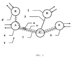
- an illustrative optical network 1 comprises nodes 2, AE connected by links 3.
- a node 2 may be a router, such as nodes A and C, an optical packet insertion and extraction multiplexer (OPADM) allowing insertion or extraction of a packet in the optical network 1 represented by a double arrow, such as the nodes A, B, D and E, or combine the two functions, such as the node A.
- OPADM optical packet insertion and extraction multiplexer
- Such an optical network 1 makes it possible to transport packets 6 between source nodes 4 capable of transmitting packets 6 in the optical network 1 and at least one destination node 5 able to receive said packets (6) from the optical network 1. It is assumed that following the description that a packet 6 is transmitted by a first source node 4, A, or respectively by a second source node 4 ', B and receives a destination node 5, E. Through the optical network 1, said packet follows a first path 7, crossing the nodes A, C and E, respectively a second path 7 'passing through the nodes B, A, C and E.
- the source optical nodes which emit packets in the optical network 1 implement a transmission method which comprises the following steps.
- an optical transmission power of the packets is determined, as a function of the destination node 5, as a function of the physical propagation parameters of the paths 7, 7 'that these packets will borrow to reach said node destination 5, so that the packets arrive at the destination node 5 with a substantially given signal-to-noise ratio, or at least with an optical signal-to-noise ratio contained in a predetermined low excursion, with respect to the other packets arriving at the said destination node 5.
- the packet is transmitted by modulating the transmission power so that it is equal to said previously determined transmission optical power.
- an excursion of the reception signal-to-noise ratio at a destination node of less than +/- 1dB / nm is satisfactory with respect to the problem posed.
- the magnitude of this tolerance range may vary depending on the specifics of the burst mode receivers employed in the network.
- the determination of the transmission optical power which will thus serve as a basis for setting the transmission power must be carried out packet by packet insofar as, for each packet, a different path 7 can be borrowed. Under certain simplifying assumptions detailed above, for a given packet, the path 7 borrowed is known in advance. It is thus possible, depending on the destination node 5 of a packet, to uniquely determine the tracking path 7, and to associate a transmission optical power. The determination of the optical transmission power can thus be carried out, for each packet, as a function of its destination node 5.
- This new determination of the optical power, challenge to each packet, must be performed for a very short period of time and at least too short to allow any return of information from the destination node 5, for the current package. It is therefore not possible to use a feedback loop or closed loop here. Thus, the determination of the optical power is necessarily carried out in an open loop.
- the transmission power must necessarily be predetermined, for example in an adjustment phase, prior to the operation phase.
- the determination of the transmission optical power can be carried out according to different embodiments.
- a first approach is to model the optical network 1 in terms of propagation quality.
- the quality of a path 7, connecting a source node 4 to a destination node 5 is determined according to the physical propagation parameters of the path 7.
- the physical parameters influencing the optical signal-to-noise ratio can for example be expressed in the form of a noise factor NF (or noise figure, NF, in English).
- a noise factor NF can be individually associated with each active constituent of the path, or globally with the path 7 itself by combining the effects of all the equipment encountered along the path.
- a first source of disturbance of the optical signal-to-noise ratio is the optical fiber segments.
- a segment of optical fiber has little influence on the optical signal-to-noise ratio and, in practice, no noise factor NF is associated with the optical fiber segments.
- Another source of disturbance is located at the level of the different optical devices or devices 2 crossed by the packet 6 along its path 7.
- Each optical device can be considered as a disturbance which is associated with a noise factor NF.
- each equipment or type of equipment can be assigned a specific noise factor, for example determined according to the characteristics indicated by the maker. Alternatively a single average noise factor can be used for all equipment.
- the noise factors NF of the successive components of a path 7 combine to determine a noise factor of the path 7.
- the length of each path 7 is compared with two length thresholds. If the path length is less than 500km, the determined transmit power is equal to x dBm. If the length of the path is between 500km and 1500km, the determined transmission power is equal to x + 2 dBm. If the length of the path is greater than 1500km, the determined transmission power is equal to x + 4 dBm, where x is a constant value.
- Another alternative approach to modeling consists in measuring the quality of the path 7, for example by measuring or determining, by means of a measurement, the overall noise factor NF of a path 7. This can be done in a prior or concomitant phase to the operation of the optical network 1 using at least one test packet for each path 7 for which the signal-to-optical noise ratio is measured. Since the transmission power at the source 4 is known, it is possible to deduce the noise factor NF from the path 7 provided that the packet does not pass through an element whose output optical power of the channel saturates. The value of the transmission power is predetermined by prior convention or can be transmitted, for example by the test packet itself. The value of the optical signal-to-noise ratio is determined by measurement at the destination node 5.
- the value of the optical signal-to-noise ratio associated with a path 7 can then be transmitted to the source node, by any transmission method, in order to make it possible subsequently to determine the transmission power of a packet 6 intended to transit via said path 7, up to said destination node 5.
- the method is applicable to any optical network 1 for which the path 7 taken by a packet 6, or at least the physical propagation parameters of the path 7, are known a priori, in order to it is possible to determine a transmission power that guarantees a given optical signal-to-noise ratio at destination 5.
- This is the case for certain optical network organizations 1 where, for example, the routing is carried out deterministically. This is the case for example simple topologies such as that of a ring network, or when the path is pre-established in a mesh.
- the transmission power data, the final optical signal-to-noise ratio and / or the physical propagation parameters are advantageously stored in a table. reference, indexed according to the path followed 7 or equivalent of the destination node 5. This allows to quickly find this data for later use to determine a transmission power for a given path.
- the approach thus developed to determine the transmission power at source 4 according to a ratio constant optical noise signal at destination 5, is a global approach over the entire path 7 from the source node 4 where the packet 6 enters the optical network 1 to the destination node 5 where the packet 6 leaves the optical network 1
- Such an approach may be contradictory with a commonly used local approach of automatically equalizing the optical powers at each node traversed.
- the method is advantageously implemented in an optical network 1 where such automatic equalization is not implemented.
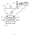
- Such a source node can for example be realized on the basis of the diagram of the figure 2 .
- the node shown has four inputs 10 and four outputs 11. Between the inputs 10 and the outputs 11 is arranged a matrix 4x4, 12 which duplicate by four each input optical signals.
- a programmable selector 13 (Wavelength Selective Switch, WSS) makes it possible to choose the signal transmitted on an output 11.
- WSS Wavelength Selective Switch
- OPADM 14 is inserted at each input 10.
- Optical amplifiers 20, 21 may be arranged at different points of the diagram, for example of the type comprising an erbium doped optical fiber (EDFA).
- EDFA erbium doped optical fiber
- the top of the figure shows a detailed view of such an OPADM 14. It comprises an input demultiplexer 15 which makes it possible to separate the signals into channels according to their frequency and a multiplexer 16 at the output.
- Each of the various channels is optionally a passing channel 17 for example to allow rerouting, or a channel equipped with an insertion box (ADD) and ejection (DROP) 18, 19. So when such housing 18, 19 is arranged on a channel corresponding to the wavelength of a particular channel, it is possible to insert or extract optical packets on this channel.
- ADD insertion box
- DROP ejection
- a node according to such a scheme makes it possible to perform the routing functions by controlling the programmable selectors 13 and the insertion / ejection functions using the insertion or ejection channels 18, 19.
- the figure 3 is a diagram of such an OPADM 14 with an optical demultiplexer 15 and an optical multiplexer 16 connected by lines 17, 18 and 19.
- the top of the figure shows a detailed view of the line 18.
- This line 18 comprises an optical segment 25 where the packets pass from left to right in the plane of the figure.
- This optical segment 25 is equipped with an insertion box 24 and a reading box 23.
- the insertion / transmission of a packet arriving via a queue 27 storing the packets to be inserted is controlled by a controller 26.
- Said controller 26 controls the setting of the transmission power according to the invention by driving the insertion unit 24, for each packet coming from the queue 27.
- the controller 26 refers, for controlling this setting, to a reference table 28 containing the predetermined transmission power, indexed according to the destination node 5 or the path 7 of the inserted / transmitted packet.
Landscapes
- Engineering & Computer Science (AREA)
- Computer Networks & Wireless Communication (AREA)
- Optical Communication System (AREA)
Claims (14)
- Verfahren zur Übertragung von Paketen (6) in einem transparenten optischen Netzwerk (1) mit mehreren Quellknoten (4), die fähig sind, Pakete (6) in dem optischen Netzwerk (1) auszusenden, und mindestens einem Zielknoten (5), der fähig ist, die besagten Pakete (6) des optischen Netzwerks (1) zu empfangen, dadurch gekennzeichnet, dass es die folgenden Schritte umfasst:- Bestimmen, für jeden Quellknoten (4), einer von dem Zielknoten (5) abhängigen optischen Sendeleistung, so dass die besagten Pakete (6), wenn sie mit der besagten Sendeleistung ausgesendet werden, ungeachtet derer Quellknoten mit im Wesentlichen gleichwertigen optischen Signal-Rausch-Verhältnissen am Zielknoten (5) ankommen, wobei das Bestimmen von den physischen Verbreitungsparametern der optischen Vorrichtungen (2), die längs eines Pfads (7), welcher den aussendenden Quellknoten (4) mit dem besagten Zielknoten (5) verbindet, durchquert werden, abhängt oder ausgehend von einem am Zielknoten (5) anhand mindestens eines Testpakets gemessenen abschließenden Signal-Rausch-Verhältnis erfolgt;- Aussenden der besagten Pakete (6) mit der besagten bestimmten optischen Sendeleistung.
- Verfahren zur Übertragung nach Anspruch 1, wobei die optischen Signal-Rausch-Verhältnisse als im Wesentlichen gleichwertig betrachtet werden, wenn der Unterschied weniger als +/-1 dB/nm beträgt.
- Verfahren zur Übertragung nach Anspruch 1 oder 2, wobei die besagten physischen Verbreitungsparameter die Länge des besagten Pfads (7) umfassen.
- Verfahren zur Übertragung nach einem beliebigen der Ansprüche 1 bis 3, wobei die besagten physischen Verbreitungsparameter die Anzahl der längs des besagten Pfads (7) angeordneten optischen Vorrichtungen (2) umfassen.
- Verfahren zur Übertragung nach einem beliebigen der Ansprüche 1 bis 4, wobei die besagte optische Sendeleistung durch eine steigende Funktion der Länge des besagten Pfads (7) bestimmt wird.
- Verfahren zur Übertragung nach Anspruch 5, wobei die besagte Funktion die Pfadlängen in eine gegebene Anzahl von Klassen unterteilt und einer jeden Klasse eine optische Sendeleistung zugeordnet wird.
- Verfahren zur Übertragung nach einem beliebigen der Ansprüche 1 bis 6, wobei die besagte optische Sendleistung, sobald sie bestimmt wurde, für eine schnelle Verwendung bei den zukünftigen Bestimmungsschritten in einer Bezugstabelle gespeichert wird.
- Transparentes optisches Netzwerk (1) für den Transport von Paketen (6), mit mehreren Quellknoten (4), die fähig sind, Pakete (6) in dem optischen Netzwerk (1) auszusenden, und mindestens einem Zielknoten (5), der fähig ist, die besagten Pakete (6) des optischen Netzwerks (1) zu empfangen, wobei ein jeder der Quellknoten (4) dadurch gekennzeichnet ist, dass er umfasst:- Mittel zum Bestimmen einer von dem Zielknoten (5) abhängigen optischen Sendeleistung, so dass ein Paket (6), wenn es mit der besagten Sendeleistung ausgesendet wird, mit einem im Wesentlichen mit dem optischen Signal-Rausch-Verhältnis eines anderen Pakets, welches von einem anderen Quellknoten an dem Zielknoten (5) ankommt, gleichwertigen optischen Signal-Rausch-Verhältnis am Zielknoten (5) ankommt, wobei das Bestimmen von den physischen Verbreitungsparametern der optischen Vorrichtungen (2), die längs eines Pfads (7), welcher den Quellknoten (4) mit dem besagten Zielknoten (5) verbindet, durchquert werden, abhängt oder ausgehend von einem am Zielknoten (5) anhand mindestens eines Testpakets gemessenen abschließenden Signal-Rausch-Verhältnis erfolgt;- Mittel zum Aussenden des besagten Paketes (6) mit der besagten bestimmten optischen Sendeleistung.
- Netzwerk nach Anspruch 8, wobei optische Signal-Rausch-Verhältnisse als im Wesentlich gleichwertig betrachtet werden, wenn der Unterschied weniger als +/-1 dB/nm beträgt.
- Netzwerk nach Anspruch 8 oder 9, wobei die besagten physischen Verbreitungsparameter die Länge des besagten Pfads (7) umfassen.
- Netzwerk nach einem beliebigen der Ansprüche 8 bis 10, wobei die besagten physischen Verbreitungsparameter die Anzahl der längs des besagten Pfads (7) angeordneten optischen Vorrichtungen (2) umfassen.
- Netzwerk nach einem beliebigen der Ansprüche 8 bis 11, wobei die besagte optische Sendeleistung durch eine steigende Funktion der Länge des besagten Pfads (7) bestimmt wird.
- Netzwerk nach Anspruch 12, wobei die besagte Funktion die Pfadlängen in eine gegebene Anzahl von Klassen unterteilt und einer jeden Klasse eine optische Sendeleistung zugeordnet wird.
- Netzwerk nach einem beliebigen der Ansprüche 8 bis 13, weiterhin umfassend eine Bezugstabelle zum Speichern der bestimmten optischen Sendleistung für eine schnelle zukünftige Verwendung.
Applications Claiming Priority (1)
| Application Number | Priority Date | Filing Date | Title |
|---|---|---|---|
| FR0954141A FR2947128B1 (fr) | 2009-06-19 | 2009-06-19 | Noeud optique et procede de transmission de paquets dans un reseau optique |
Publications (2)
| Publication Number | Publication Date |
|---|---|
| EP2265036A1 EP2265036A1 (de) | 2010-12-22 |
| EP2265036B1 true EP2265036B1 (de) | 2012-08-29 |
Family
ID=41625994
Family Applications (1)
| Application Number | Title | Priority Date | Filing Date |
|---|---|---|---|
| EP10155784A Not-in-force EP2265036B1 (de) | 2009-06-19 | 2010-03-08 | Optischer Knoten und Verfahren zur Übertragung optischer Pakete |
Country Status (2)
| Country | Link |
|---|---|
| EP (1) | EP2265036B1 (de) |
| FR (1) | FR2947128B1 (de) |
Families Citing this family (1)
| Publication number | Priority date | Publication date | Assignee | Title |
|---|---|---|---|---|
| CN116707645A (zh) * | 2023-05-25 | 2023-09-05 | 西安电子科技大学 | 基于神经网络的反馈式光输入功率预测方法 |
Family Cites Families (1)
| Publication number | Priority date | Publication date | Assignee | Title |
|---|---|---|---|---|
| JPH10164020A (ja) * | 1996-11-29 | 1998-06-19 | Nec Corp | 光波長多重中継伝送システムおよびその光s/n比等化方法 |
-
2009
- 2009-06-19 FR FR0954141A patent/FR2947128B1/fr not_active Expired - Fee Related
-
2010
- 2010-03-08 EP EP10155784A patent/EP2265036B1/de not_active Not-in-force
Also Published As
| Publication number | Publication date |
|---|---|
| FR2947128A1 (fr) | 2010-12-24 |
| EP2265036A1 (de) | 2010-12-22 |
| FR2947128B1 (fr) | 2011-10-28 |
Similar Documents
| Publication | Publication Date | Title |
|---|---|---|
| EP1155531B1 (de) | System und verfahren zur messung der übertragungsdauer und der verluste in einem hochleistungs-telekommunikationsnetz | |
| EP0230691B1 (de) | Einrichtung zur Senderleistungssteuerung einer Richtfunkstrecke | |
| FR2965686A1 (fr) | Technique de determination d'un temps de propagation d'un signal optique entre deux equipements optiques au moyen d'une liaison optique | |
| FR2533094A1 (fr) | Methode de controle d'un systeme de transmission numerique, systeme et repeteurs appliquant cette methode | |
| FR3065302A1 (fr) | Procede de generation et de controle de trafic de test, port d'entree ou de sortie de commutateur et commutateur associes | |
| FR3007537A1 (fr) | Reseau optique en anneau, integre sur puce (onoc) et procede associe | |
| WO2010136715A1 (fr) | Procédé de gestion de chemins entre un noeud source et un noeud destinataire au niveau de la couche de liaison, noeud source et table correspondants | |
| FR2953352A1 (fr) | Procede de controle d'un etat de charge d'un lien physique entre deux noeuds de reseau physiques portant une pluralite de liens virtuels | |
| US9294194B2 (en) | Network monitoring using thin film splitters and avalanche photodiode detectors in multimode application | |
| EP2265036B1 (de) | Optischer Knoten und Verfahren zur Übertragung optischer Pakete | |
| FR2950765A1 (fr) | Dispositif de commutation de paquets optiques | |
| FR2750270A1 (fr) | Egaliseur-combineur pour recepteur en diversite, recepteur integrant un tel egaliseur-combineur, et procede de reception en diversite correspondant | |
| EP2572479A1 (de) | Routingverfahren für verbindungsstatus zum routen von datenströmen in einem mesh-netzwerk mit anhand von dreifachstatusverbindungen verbundenen knoten | |
| EP1428333B1 (de) | Optisches ringnetzwerk mit doppeltem optischem bus | |
| EP2878086A1 (de) | Unidirektionale multicast-systeme | |
| EP2606655B1 (de) | Verfahren zur umschaltung eines optischen datenstroms, computerprogrammprodukt sowie zugehörige speichervorrichtung und knoten | |
| EP3753259A1 (de) | Steuerungsebene für ein optisches netzwerk zur übertragung von mehrträgerdatenbursts mit dynamischer anpassung der lernsequenz | |
| WO2017016854A1 (fr) | Procede de determination d'une route dans un reseau cpl | |
| EP2263339B1 (de) | Vorrichtung und verfahren zur verwaltung der sendeleistung einer optischen quelle auf basis der optischen verluste einer optischen verbindung | |
| EP1548966A1 (de) | Verfahren zur Verwaltung eines optischen Übertragungsnetzwerks | |
| FR2971108A1 (fr) | Systeme de determination d'un temps de propagation d'un signal optique entre deux equipements optiques au moyen d'une liaison optique | |
| EP0998164B1 (de) | Verfahren zur Überwachung des Paketverlustes in einem Kommunikationssystem | |
| WO2018096286A1 (fr) | Détermination de nœuds relais régénérateurs compris dans une ligne de transmission d'un réseau optique | |
| EP4475454A1 (de) | Verfahren zur verwaltung einer funkschnittstelle einer kommunikationsvorrichtung | |
| WO2023111064A1 (fr) | Reseau de communication avionique |
Legal Events
| Date | Code | Title | Description |
|---|---|---|---|
| PUAI | Public reference made under article 153(3) epc to a published international application that has entered the european phase |
Free format text: ORIGINAL CODE: 0009012 |
|
| AK | Designated contracting states |
Kind code of ref document: A1 Designated state(s): AT BE BG CH CY CZ DE DK EE ES FI FR GB GR HR HU IE IS IT LI LT LU LV MC MK MT NL NO PL PT RO SE SI SK SM TR |
|
| AX | Request for extension of the european patent |
Extension state: AL BA ME RS |
|
| 17P | Request for examination filed |
Effective date: 20110622 |
|
| RIC1 | Information provided on ipc code assigned before grant |
Ipc: H04Q 11/00 20060101AFI20111121BHEP |
|
| GRAP | Despatch of communication of intention to grant a patent |
Free format text: ORIGINAL CODE: EPIDOSNIGR1 |
|
| RAP1 | Party data changed (applicant data changed or rights of an application transferred) |
Owner name: ALCATEL LUCENT |
|
| RIN1 | Information on inventor provided before grant (corrected) |
Inventor name: HENRI, PASCAL Inventor name: ZAMI, THIERRY |
|
| GRAS | Grant fee paid |
Free format text: ORIGINAL CODE: EPIDOSNIGR3 |
|
| GRAA | (expected) grant |
Free format text: ORIGINAL CODE: 0009210 |
|
| AK | Designated contracting states |
Kind code of ref document: B1 Designated state(s): AT BE BG CH CY CZ DE DK EE ES FI FR GB GR HR HU IE IS IT LI LT LU LV MC MK MT NL NO PL PT RO SE SI SK SM TR |
|
| REG | Reference to a national code |
Ref country code: GB Ref legal event code: FG4D Free format text: NOT ENGLISH |
|
| REG | Reference to a national code |
Ref country code: CH Ref legal event code: EP |
|
| REG | Reference to a national code |
Ref country code: AT Ref legal event code: REF Ref document number: 573603 Country of ref document: AT Kind code of ref document: T Effective date: 20120915 |
|
| REG | Reference to a national code |
Ref country code: IE Ref legal event code: FG4D Free format text: LANGUAGE OF EP DOCUMENT: FRENCH |
|
| REG | Reference to a national code |
Ref country code: DE Ref legal event code: R096 Ref document number: 602010002580 Country of ref document: DE Effective date: 20121025 |
|
| REG | Reference to a national code |
Ref country code: AT Ref legal event code: MK05 Ref document number: 573603 Country of ref document: AT Kind code of ref document: T Effective date: 20120829 |
|
| REG | Reference to a national code |
Ref country code: NL Ref legal event code: VDEP Effective date: 20120829 |
|
| REG | Reference to a national code |
Ref country code: LT Ref legal event code: MG4D Effective date: 20120829 |
|
| PG25 | Lapsed in a contracting state [announced via postgrant information from national office to epo] |
Ref country code: LT Free format text: LAPSE BECAUSE OF FAILURE TO SUBMIT A TRANSLATION OF THE DESCRIPTION OR TO PAY THE FEE WITHIN THE PRESCRIBED TIME-LIMIT Effective date: 20120829 Ref country code: AT Free format text: LAPSE BECAUSE OF FAILURE TO SUBMIT A TRANSLATION OF THE DESCRIPTION OR TO PAY THE FEE WITHIN THE PRESCRIBED TIME-LIMIT Effective date: 20120829 Ref country code: HR Free format text: LAPSE BECAUSE OF FAILURE TO SUBMIT A TRANSLATION OF THE DESCRIPTION OR TO PAY THE FEE WITHIN THE PRESCRIBED TIME-LIMIT Effective date: 20120829 Ref country code: IS Free format text: LAPSE BECAUSE OF FAILURE TO SUBMIT A TRANSLATION OF THE DESCRIPTION OR TO PAY THE FEE WITHIN THE PRESCRIBED TIME-LIMIT Effective date: 20121229 Ref country code: FI Free format text: LAPSE BECAUSE OF FAILURE TO SUBMIT A TRANSLATION OF THE DESCRIPTION OR TO PAY THE FEE WITHIN THE PRESCRIBED TIME-LIMIT Effective date: 20120829 Ref country code: NO Free format text: LAPSE BECAUSE OF FAILURE TO SUBMIT A TRANSLATION OF THE DESCRIPTION OR TO PAY THE FEE WITHIN THE PRESCRIBED TIME-LIMIT Effective date: 20121129 |
|
| PG25 | Lapsed in a contracting state [announced via postgrant information from national office to epo] |
Ref country code: LV Free format text: LAPSE BECAUSE OF FAILURE TO SUBMIT A TRANSLATION OF THE DESCRIPTION OR TO PAY THE FEE WITHIN THE PRESCRIBED TIME-LIMIT Effective date: 20120829 Ref country code: GR Free format text: LAPSE BECAUSE OF FAILURE TO SUBMIT A TRANSLATION OF THE DESCRIPTION OR TO PAY THE FEE WITHIN THE PRESCRIBED TIME-LIMIT Effective date: 20121130 Ref country code: PT Free format text: LAPSE BECAUSE OF FAILURE TO SUBMIT A TRANSLATION OF THE DESCRIPTION OR TO PAY THE FEE WITHIN THE PRESCRIBED TIME-LIMIT Effective date: 20121231 Ref country code: SI Free format text: LAPSE BECAUSE OF FAILURE TO SUBMIT A TRANSLATION OF THE DESCRIPTION OR TO PAY THE FEE WITHIN THE PRESCRIBED TIME-LIMIT Effective date: 20120829 Ref country code: SE Free format text: LAPSE BECAUSE OF FAILURE TO SUBMIT A TRANSLATION OF THE DESCRIPTION OR TO PAY THE FEE WITHIN THE PRESCRIBED TIME-LIMIT Effective date: 20120829 |
|
| PG25 | Lapsed in a contracting state [announced via postgrant information from national office to epo] |
Ref country code: CZ Free format text: LAPSE BECAUSE OF FAILURE TO SUBMIT A TRANSLATION OF THE DESCRIPTION OR TO PAY THE FEE WITHIN THE PRESCRIBED TIME-LIMIT Effective date: 20120829 Ref country code: EE Free format text: LAPSE BECAUSE OF FAILURE TO SUBMIT A TRANSLATION OF THE DESCRIPTION OR TO PAY THE FEE WITHIN THE PRESCRIBED TIME-LIMIT Effective date: 20120829 Ref country code: RO Free format text: LAPSE BECAUSE OF FAILURE TO SUBMIT A TRANSLATION OF THE DESCRIPTION OR TO PAY THE FEE WITHIN THE PRESCRIBED TIME-LIMIT Effective date: 20120829 Ref country code: NL Free format text: LAPSE BECAUSE OF FAILURE TO SUBMIT A TRANSLATION OF THE DESCRIPTION OR TO PAY THE FEE WITHIN THE PRESCRIBED TIME-LIMIT Effective date: 20120829 Ref country code: DK Free format text: LAPSE BECAUSE OF FAILURE TO SUBMIT A TRANSLATION OF THE DESCRIPTION OR TO PAY THE FEE WITHIN THE PRESCRIBED TIME-LIMIT Effective date: 20120829 Ref country code: ES Free format text: LAPSE BECAUSE OF FAILURE TO SUBMIT A TRANSLATION OF THE DESCRIPTION OR TO PAY THE FEE WITHIN THE PRESCRIBED TIME-LIMIT Effective date: 20121210 |
|
| PG25 | Lapsed in a contracting state [announced via postgrant information from national office to epo] |
Ref country code: PL Free format text: LAPSE BECAUSE OF FAILURE TO SUBMIT A TRANSLATION OF THE DESCRIPTION OR TO PAY THE FEE WITHIN THE PRESCRIBED TIME-LIMIT Effective date: 20120829 Ref country code: SK Free format text: LAPSE BECAUSE OF FAILURE TO SUBMIT A TRANSLATION OF THE DESCRIPTION OR TO PAY THE FEE WITHIN THE PRESCRIBED TIME-LIMIT Effective date: 20120829 Ref country code: IT Free format text: LAPSE BECAUSE OF FAILURE TO SUBMIT A TRANSLATION OF THE DESCRIPTION OR TO PAY THE FEE WITHIN THE PRESCRIBED TIME-LIMIT Effective date: 20120829 |
|
| PLBE | No opposition filed within time limit |
Free format text: ORIGINAL CODE: 0009261 |
|
| STAA | Information on the status of an ep patent application or granted ep patent |
Free format text: STATUS: NO OPPOSITION FILED WITHIN TIME LIMIT |
|
| PG25 | Lapsed in a contracting state [announced via postgrant information from national office to epo] |
Ref country code: BG Free format text: LAPSE BECAUSE OF FAILURE TO SUBMIT A TRANSLATION OF THE DESCRIPTION OR TO PAY THE FEE WITHIN THE PRESCRIBED TIME-LIMIT Effective date: 20121129 |
|
| 26N | No opposition filed |
Effective date: 20130530 |
|
| REG | Reference to a national code |
Ref country code: DE Ref legal event code: R097 Ref document number: 602010002580 Country of ref document: DE Effective date: 20130530 |
|
| BERE | Be: lapsed |
Owner name: ALCATEL LUCENT Effective date: 20130331 |
|
| PG25 | Lapsed in a contracting state [announced via postgrant information from national office to epo] |
Ref country code: MC Free format text: LAPSE BECAUSE OF NON-PAYMENT OF DUE FEES Effective date: 20130331 |
|
| REG | Reference to a national code |
Ref country code: FR Ref legal event code: GC Effective date: 20131018 |
|
| PG25 | Lapsed in a contracting state [announced via postgrant information from national office to epo] |
Ref country code: CY Free format text: LAPSE BECAUSE OF FAILURE TO SUBMIT A TRANSLATION OF THE DESCRIPTION OR TO PAY THE FEE WITHIN THE PRESCRIBED TIME-LIMIT Effective date: 20120829 |
|
| REG | Reference to a national code |
Ref country code: IE Ref legal event code: MM4A |
|
| PG25 | Lapsed in a contracting state [announced via postgrant information from national office to epo] |
Ref country code: IE Free format text: LAPSE BECAUSE OF NON-PAYMENT OF DUE FEES Effective date: 20130308 Ref country code: BE Free format text: LAPSE BECAUSE OF NON-PAYMENT OF DUE FEES Effective date: 20130331 |
|
| PG25 | Lapsed in a contracting state [announced via postgrant information from national office to epo] |
Ref country code: MT Free format text: LAPSE BECAUSE OF FAILURE TO SUBMIT A TRANSLATION OF THE DESCRIPTION OR TO PAY THE FEE WITHIN THE PRESCRIBED TIME-LIMIT Effective date: 20120829 |
|
| REG | Reference to a national code |
Ref country code: CH Ref legal event code: PCOW Free format text: NEW ADDRESS: 148/152 ROUTE DE LA REINE, 92100 BOULOGNE-BILLANCOURT (FR) |
|
| REG | Reference to a national code |
Ref country code: CH Ref legal event code: PL |
|
| REG | Reference to a national code |
Ref country code: FR Ref legal event code: RG Effective date: 20141016 |
|
| PG25 | Lapsed in a contracting state [announced via postgrant information from national office to epo] |
Ref country code: CH Free format text: LAPSE BECAUSE OF NON-PAYMENT OF DUE FEES Effective date: 20140331 Ref country code: LI Free format text: LAPSE BECAUSE OF NON-PAYMENT OF DUE FEES Effective date: 20140331 |
|
| REG | Reference to a national code |
Ref country code: FR Ref legal event code: PLFP Year of fee payment: 6 |
|
| PG25 | Lapsed in a contracting state [announced via postgrant information from national office to epo] |
Ref country code: SM Free format text: LAPSE BECAUSE OF FAILURE TO SUBMIT A TRANSLATION OF THE DESCRIPTION OR TO PAY THE FEE WITHIN THE PRESCRIBED TIME-LIMIT Effective date: 20120829 |
|
| PG25 | Lapsed in a contracting state [announced via postgrant information from national office to epo] |
Ref country code: TR Free format text: LAPSE BECAUSE OF FAILURE TO SUBMIT A TRANSLATION OF THE DESCRIPTION OR TO PAY THE FEE WITHIN THE PRESCRIBED TIME-LIMIT Effective date: 20120829 |
|
| PG25 | Lapsed in a contracting state [announced via postgrant information from national office to epo] |
Ref country code: LU Free format text: LAPSE BECAUSE OF NON-PAYMENT OF DUE FEES Effective date: 20130308 Ref country code: MK Free format text: LAPSE BECAUSE OF FAILURE TO SUBMIT A TRANSLATION OF THE DESCRIPTION OR TO PAY THE FEE WITHIN THE PRESCRIBED TIME-LIMIT Effective date: 20120829 Ref country code: HU Free format text: LAPSE BECAUSE OF FAILURE TO SUBMIT A TRANSLATION OF THE DESCRIPTION OR TO PAY THE FEE WITHIN THE PRESCRIBED TIME-LIMIT; INVALID AB INITIO Effective date: 20100308 |
|
| REG | Reference to a national code |
Ref country code: FR Ref legal event code: PLFP Year of fee payment: 7 |
|
| PGFP | Annual fee paid to national office [announced via postgrant information from national office to epo] |
Ref country code: GB Payment date: 20160321 Year of fee payment: 7 Ref country code: FR Payment date: 20160321 Year of fee payment: 7 |
|
| PGFP | Annual fee paid to national office [announced via postgrant information from national office to epo] |
Ref country code: DE Payment date: 20160330 Year of fee payment: 7 |
|
| REG | Reference to a national code |
Ref country code: DE Ref legal event code: R119 Ref document number: 602010002580 Country of ref document: DE |
|
| GBPC | Gb: european patent ceased through non-payment of renewal fee |
Effective date: 20170308 |
|
| REG | Reference to a national code |
Ref country code: FR Ref legal event code: ST Effective date: 20171130 |
|
| PG25 | Lapsed in a contracting state [announced via postgrant information from national office to epo] |
Ref country code: FR Free format text: LAPSE BECAUSE OF NON-PAYMENT OF DUE FEES Effective date: 20170331 Ref country code: DE Free format text: LAPSE BECAUSE OF NON-PAYMENT OF DUE FEES Effective date: 20171003 |
|
| PG25 | Lapsed in a contracting state [announced via postgrant information from national office to epo] |
Ref country code: GB Free format text: LAPSE BECAUSE OF NON-PAYMENT OF DUE FEES Effective date: 20170308 |