EP2264737A2 - X-ray tube bearing assembly - Google Patents
X-ray tube bearing assembly Download PDFInfo
- Publication number
- EP2264737A2 EP2264737A2 EP10166524A EP10166524A EP2264737A2 EP 2264737 A2 EP2264737 A2 EP 2264737A2 EP 10166524 A EP10166524 A EP 10166524A EP 10166524 A EP10166524 A EP 10166524A EP 2264737 A2 EP2264737 A2 EP 2264737A2
- Authority
- EP
- European Patent Office
- Prior art keywords
- anode
- ray tube
- assembly
- bearing assembly
- ball bearing
- Prior art date
- Legal status (The legal status is an assumption and is not a legal conclusion. Google has not performed a legal analysis and makes no representation as to the accuracy of the status listed.)
- Granted
Links
Images


Classifications
-
- H—ELECTRICITY
- H01—ELECTRIC ELEMENTS
- H01J—ELECTRIC DISCHARGE TUBES OR DISCHARGE LAMPS
- H01J35/00—X-ray tubes
- H01J35/02—Details
- H01J35/04—Electrodes ; Mutual position thereof; Constructional adaptations therefor
- H01J35/08—Anodes; Anti cathodes
- H01J35/10—Rotary anodes; Arrangements for rotating anodes; Cooling rotary anodes
- H01J35/101—Arrangements for rotating anodes, e.g. supporting means, means for greasing, means for sealing the axle or means for shielding or protecting the driving
- H01J35/1017—Bearings for rotating anodes
- H01J35/103—Magnetic bearings
-
- H—ELECTRICITY
- H01—ELECTRIC ELEMENTS
- H01J—ELECTRIC DISCHARGE TUBES OR DISCHARGE LAMPS
- H01J2235/00—X-ray tubes
- H01J2235/10—Drive means for anode (target) substrate
- H01J2235/1046—Bearings and bearing contact surfaces
-
- H—ELECTRICITY
- H01—ELECTRIC ELEMENTS
- H01J—ELECTRIC DISCHARGE TUBES OR DISCHARGE LAMPS
- H01J2235/00—X-ray tubes
- H01J2235/12—Cooling
- H01J2235/1204—Cooling of the anode
Definitions
- the present invention generally relates to rotating machinery.
- some example embodiments relate to an x-ray tube bearing assembly including magnetic bearing assembly components and ball bearing assembly components.
- the x-ray tube has become essential in medical diagnostic imaging, medical therapy, and various medical testing and material analysis industries. Such equipment is commonly employed in areas such as medical diagnostic examination, therapeutic radiology, semiconductor fabrication, and materials analysis.
- An x-ray tube typically includes a vacuum enclosure that contains a cathode assembly and an anode assembly.
- the vacuum enclosure may be composed of metal such as copper, glass, ceramic, or a combination thereof, and is typically disposed within an outer housing. At least a portion of the outer housing may be covered with a shielding layer (composed of, for example, lead or a similar x-ray attenuating material) for preventing the escape of x-rays produced within the vacuum enclosure.
- a cooling medium such as a dielectric oil or similar coolant, can be disposed in the volume existing between the outer housing and the vacuum enclosure in order to dissipate heat from the surface of the vacuum enclosure.
- the cathode assembly generally consists of a metallic cathode head assembly and a source of electrons highly energized for generating x-rays.
- the anode assembly which is generally manufactured from a refractory metal such as tungsten, includes a target surface that is oriented to receive electrons emitted by the cathode assembly.
- the cathode is charged with a heating current that causes electrons to "boil" off the electron source or emitter by the process of thermionic emission.
- An electric potential on the order of about 4 kV to over about 116 kV is applied between the cathode and the anode in order to accelerate electrons boiled off the emitter toward the target surface of the anode.
- X-rays are generated when the highly accelerated electrons strike the target surface.
- a bearing assembly that allows the anode to rotate within the x-ray tube.
- a ball bearing assembly One type of bearing assembly sometimes used in x-ray tubes. While conventional ball bearing assemblies can be relatively inexpensive, they can also be relatively noisy and the noise can be a source of discomfort or irritation for medical patients and other x-ray tube users and operators.
- Another type of bearing assembly sometimes used in x-ray tubes is a magnetic bearing assembly. While conventional magnetic bearing assemblies can be relatively quiet, they can also be relatively expensive, increasing the cost of x-ray tubes in which they are used.
- rotating anode-type x-ray tubes may regularly experience temperatures exceeding 1200°C due, at least in part, to the impingement of the highly accelerated electrons on the rotating anode.
- the high temperatures can cause shifting of portions of the anode, cracking, distressing, warping, and other material failures. Material failures can result in errors in the resultant x-ray image. Consequently, heat must be managed in many x-ray tubes
- example embodiments of the invention relate to an x-ray tube bearing assembly including magnetic and ball bearing components.
- an x-ray tube comprises an evacuated enclosure and a cathode disposed within the evacuated enclosure.
- An anode is also disposed within the evacuated enclosure opposite the cathode so as to receive electrons emitted by the cathode.
- a rotor sleeve is coupled to the anode, the rotor sleeve being responsive to applied electromagnetic fields such that a rotational motion is imparted to the anode.
- a magnetic assist bearing assembly rotatably supports the anode.
- an active magnetic assist bearing assembly comprises a ball bearing assembly, means for detecting, and one or more magnetic actuators.
- the ball bearing assembly comprises a shaft coupled to a component configured to rotate.
- the ball bearing assembly shoulders a first portion of a load exerted by the component on the active magnetic assist bearing assembly during rotation of the component.
- the means for detecting detect a load exerted on the active magnetic assist bearing assembly by the component.
- the magnetic actuators are disposed about a rotor sleeve that is coupled to the component. The magnetic actuators shoulder a second portion of the load during rotation of the component.
- an x-ray tube comprises an evacuated enclosure and a cathode disposed within the evacuated enclosure.
- An anode is also disposed within the evacuated enclosure opposite the cathode so as to receive electrons emitted by the cathode.
- the anode defines a cavity extending from the top of the anode towards the bottom of the anode.
- the cavity is substantially centered about a geometric axis of rotation of the anode.
- a rotor sleeve is coupled to the anode and is responsive to applied electromagnetic fields such that a rotational motion is imparted to the anode.
- An active cooling system is at least partially disposed within the evacuated enclosure.
- the active cooling system comprises a cooling shaft extending into the cavity defined by the anode.
- a passive magnetic assist bearing assembly comprises a ball bearing assembly, a ferromagnetic shaft, and one or more permanent magnets.
- the ball bearing assembly comprises a shaft coupled to a component configured to rotate. The ball bearing assembly shoulders a first portion of a load exerted by the component on the passive magnetic assist bearing assembly during rotation of the component.
- the ferromagnetic shaft is coupled to the component and has an axis of rotation that is substantially collinear with an axis of rotation of the component.
- the one or more permanent magnets are spaced apart from the ferromagnetic shaft. The one or more permanent magnets utilize magnetic fields to exert magnetic forces on the ferromagnetic shaft to shoulder a second portion of the load during rotation of the component.
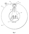
- Figure 1 is a depiction of one environment wherein an x-ray tube including an embodiment of a magnetic assist bearing assembly may be used;
- Figure 2A is a simplified double cross-sectional depiction of an x-ray tube according to an embodiment of the invention including an active magnetic assist bearing assembly;
- Figure 2B is a partial cross-sectional view of the x-ray tube of Figure 2A ;
- Figure 3 is a partial cross-sectional depiction of a stationary x-ray tube and various loads that can be exerted on a rotating anode of the x-ray tube;
- Figures 4A and 4B are partial cross-sectional views of an x-ray tube mounted to a rotatable gantry in two different configurations and various loads that can be exerted on a rotating anode of the x-ray tube;
- Figure 5A is an overhead plan view and Figure 5B is a partial cross-sectional view of an x-ray tube according to another embodiment of the invention including a passive magnetic assist bearing assembly; and
- Figure 6 is a partial cross-sectional view of an x-ray tube according to yet another embodiment of the invention including a passive magnetic assist bearing assembly.
- Embodiments of the x-ray tube may employ an active or passive magnetic assist bearing (“MAB") assembly to rotatably support one or more rotating components of the x-ray tube.
- Embodiments of the x-ray tube may, among other things, help reduce noise caused by the rotating components of the x-ray tube by employing one or more magnetic actuators or permanent magnets to shoulder a substantial portion of the load of the rotating components.
- embodiments of the x-ray tube may be comparatively less expensive than an x-ray tube employing a conventional magnetic bearing assembly by utilizing one or more ball bearing assemblies to shoulder a remaining portion of the load. Note that the principles disclosed herein can also be applied to other x-ray tubes or devices, or any other rotating machinery, where reduced noise is desired without the expense of a conventional magnetic bearing assembly.
- Figure 1 depicts one operating environment in which an x-ray tube having an active or passive MAB assembly made in accordance with embodiments of the present invention can be utilized.
- Figure 1 discloses a CT scanner depicted at 100, which generally comprises a rotatable gantry 102 and a patient platform 104.
- An x-ray tube 106 is shown mounted to the gantry 102 of the scanner 100. In operation, the gantry 102 rotates about a patient lying on the platform 104.
- the x-ray tube 106 is selectively energized during this rotation, thereby producing a beam of x-rays 108 that emanate from the x-ray tube 106 substantially as a conically diverging beam, the path of which is generally indicated at 110 in Figure 1 .
- the x-rays 108 are received by a detector array 112.
- the x-ray information received by the detector array 112 can be manipulated into images of internal portions of the patient's body to be used for medical evaluation and diagnostics.
- the x-ray tube 106 is shown in cross-section and depicts various components of the x-ray tube 106, including an outer housing 114, an evacuated enclosure 116, and an anode 118 disposed inside the evacuated enclosure 116.
- the x-rays 108 in beam path 110 are produced when energized electrons impinge on the anode 118, as will be described in greater detail below.
- Figure 1 discloses one example environment in which an x-ray tube 106 according to embodiments of the invention might be utilized. However, it will be appreciated that there are other environments for which embodiments of the x-ray tube 106 would find use and application.
- FIG. 2A illustrates an example rotating anode-type x-ray tube, designated generally at 200.
- the x-ray tube 200 of Figure 2A may correspond to the x-ray tube 106 of Figure 1 .
- x-ray tube 200 includes an outer housing 202, within which is disposed an evacuated enclosure 204.
- a cooling fluid (not shown) can also be disposed within the outer housing 202 and circulated around the evacuated enclosure 204 to assist in x-ray tube 200 cooling and to provide electrical isolation between the evacuated enclosure 204 and the outer housing 202.
- the cooling fluid may comprise dielectric oil, which exhibits desirable thermal and electrical insulating properties for some applications, although cooling fluids other than dielectric oil can alternately or additionally be implemented in the x-ray tube 200.
- an anode 206 and a cathode 208 Disposed within the evacuated enclosure 204 are an anode 206 and a cathode 208.
- the anode 206 is spaced apart from and oppositely disposed to the cathode 208, and may be at least partially composed of a thermally conductive material such as copper or a molybdenum alloy.
- the anode 206 and cathode 208 are connected in an electrical circuit that allows for the application of a high voltage potential between the anode 206 and the cathode 208.
- the cathode 208 includes a filament (not shown) that is connected to an appropriate power source and, during operation, an electrical current is passed through the filament to cause electrons to be emitted from the cathode 208 by thermionic emission.
- the application of a high voltage differential between the anode 206 and the cathode 208 then causes the electrons to accelerate from the cathode filament toward a focal track 210 that is positioned on a target 212 of the anode 206.
- the focal track 210 is typically composed of tungsten or other material(s) having a high atomic ("high Z") number. As the electrons accelerate, they gain a substantial amount of kinetic energy, and upon striking the target material on the focal track 210, some of this kinetic energy is converted into electromagnetic waves of very high frequency, i.e., x-rays 108, shown in Figure 1 .
- the focal track 210 is oriented so that emitted x-rays are directed toward an evacuated enclosure window 214.
- the evacuated enclosure window 214 is comprised of an x-ray transmissive material that is positioned within a port defined in a wall of the evacuated enclosure 204 at a point aligned with the focal track 210.
- An outer housing window 216 is disposed so as to be at least partially aligned with the evacuated enclosure window 214.
- the outer housing window 216 is similarly comprised of an x-ray transmissive material and is disposed in a port defined in a wall of the outer housing 202.
- the x-rays that emanate from the evacuated enclosure 204 and pass through the outer housing window 216 may do so substantially as a conically diverging beam.
- the anode 206 is rotatably supported by an anode support assembly 218, as best seen in Figure 2B , which illustrates some aspects of the x-ray tube 200 in simplified cross-section.
- the anode support assembly 218 generally comprises an active MAB assembly 220 and a rotor sleeve 222.
- the anode support assembly 218 can comprise a passive MAB assembly ( Figures 5 and 6 ) and the rotor sleeve 222.
- the active MAB assembly 220 is at least partially disposed in the evacuated enclosure 204, and is described in additional detail below.
- a portion of the active MAB assembly 220 is attached to a portion of the evacuated enclosure 204 such that the anode 206 is rotatably supported by the active MAB assembly 220, thereby enabling the anode 206 to rotate with respect to the evacuated enclosure 204.
- a stator 224 is disposed about the rotor sleeve 222 and utilizes rotational electromagnetic fields to cause the rotor sleeve 222 to rotate.
- the rotor sleeve 222 is attached to the anode 206, thereby providing the needed rotation of the anode 206 during x-ray tube 200 operation.
- the evacuated enclosure 204 can be fixedly secured to the outer housing 202 via a plurality of flanges 226 formed with the evacuated enclosure 204.
- one or more sensors can be positioned between the evacuated enclosure 204 and outer housing 202 to detect a load exerted on the active MAB assembly 220 by the anode 206.
- the one or more sensors can be disposed on the flange 226 between the outer housing 202 and evacuated enclosure 204.
- the load exerted on the active MAB assembly 220 can be detected indirectly, e.g. , by detecting the load transferred from the active MAB assembly 220 to the evacuated enclosure 204.
- the active MAB assembly 220 may then employ load detection to rotatably support the anode 206.
- some embodiments of the x-ray tube 200 can include an active cooling system at least partially disposed within the evacuated enclosure 204 for transferring heat away from the anode 206.
- the anode 206 defines a cavity 228 extending from the top of the anode 206 towards the bottom of the anode 206, as shown in Figure 2B .
- the cavity 228 may be substantially cylindrical in shape and can be substantially centered about a geometric axis of rotation of the anode 206.
- the active cooling system can include a cooling shaft 230 extending into the cavity 228 defined by the anode 206.
- the portion of the cooling shaft 230 extending into the cavity 228 may be smaller than the cavity 228 and can be complementary in shape to allow the anode 206 to rotate with respect to the cooling shaft 230 during operation.
- a liquid metal interface 232 can be provided in the space between cooling shaft 230 and the walls of cavity 228 to facilitate heat transfer from the anode 206 to the cooling shaft 230, the liquid metal interface 232 thermally coupling the active cooling system to the anode 206.
- the liquid metal interface 232 comprises a metal material existing in liquid form over a temperature range that includes the range of operating temperatures of the anode 206.
- the liquid metal interface 232 comprises one or more of gallium, indium, or tin, or the like or any combination thereof, including gallium eutectic, for example.
- the cooling shaft 230 can include one or more channels 234 formed in the cooling shaft 230.
- the active cooling system may further include a cooling fluid (not shown) that is circulated through the channels 234 by a pump (not shown), for instance, to carry heat away from the anode 206 to a heat sink (not shown).
- a substrate 236 can be coupled to the anode 206 to further facilitate heat transfer from the anode 206 to the cooling shaft 230.
- the substrate 236 can be coupled to the anode 206 at first interface 238A and second interface 238B.
- the substrate 236 can be coupled to the anode 206 at first and second interfaces 238A, 238B via welding or brazing, for instance.
- the substrate 236 can comprise graphite.
- the substrate 236 can increase the heat conduction paths available from the focal track 210 to the cooling shaft 230, effectively increasing the heat transfer ability of the anode 206. For instance, heat can be transferred from the focal track 210 to the cooling shaft 230 via heat conduction path 240. Alternately or additionally, heat can be transferred from the focal track 210 to the cooling shaft 230 via additional heat conduction paths 242. By providing greater heat conduction to the actively cooled system via additional heat conduction paths 242, the anode 206 can be operated a relatively longer period of time without overheating than a comparable anode that lacks additional heat conduction paths 242.
- the substrate 236 can be coupled to the anode 206 at only one of first or second interface 238A or 238B.
- the substrate 236 can be coupled to the anode 206 at first interface 238A, with a spatial separation from the anode 206 at second interface 238B.
- the substrate 236 can generally receive, store and radiatively dissipate heat from the focal track 210, without providing the additional heat conduction paths 242.
- Figure 2A discloses one example environment in which an active cooling system and/or an active MAB assembly 220 and/or a passive MAB assembly according to embodiments of the invention might be utilized.
- an active cooling system and/or an active MAB assembly 220 and/or a passive MAB assembly according to embodiments of the invention might be utilized.
- FIG. 2A discloses one example environment in which an active cooling system and/or an active MAB assembly 220 and/or a passive MAB assembly according to embodiments of the invention might be utilized.
- active cooling system active cooling system
- active MAB assembly 220 and/or a passive MAB assembly would find use and application.
- the active MAB assembly 220 rotatably supports the anode 206 and other rotating components coupled to the anode 206, such as the substrate 236, the rotor sleeve 222, and the like.
- the active MAB assembly 220 will be discussed as rotatably supporting the anode 206, with the understanding that the active MAB assembly 220 also rotatably supports the other rotating components coupled to the anode 206.
- Rotatably supporting the anode 206 can include shouldering a load exerted on the active MAB assembly 220 by the anode 206 to maintain the anode 206 in a predetermined position within the x-ray tube 200 while allowing the anode 206 to rotate within the x-ray tube 200.
- the load exerted on the active MAB assembly 220 by the anode 206 can comprise one or more axial, radial, and/or torque loads, as will be explained in greater detail below.
- Figures 3-4B three simplified diagrams are provided to better understand some of the loads that can act on a rotating anode under various operating conditions.
- the anodes depicted in Figures 3-4B may correspond, for example, to the anode 206 of Figures 2A and 2B .
- Figure 3 depicts a simplified cross-sectional side view of an x-ray tube 300 comprising an anode 302, a rotor sleeve 304 and a stator 306.
- the x-ray tube 300 can comprise a stationary x-ray tube oriented such that the weight of the anode 302, represented by the force W, is substantially parallel to an axis of rotation A of the anode 302. In other stationary x-ray tube orientations, however, the weight W of the anode 302 may be at some other angle relative to the axis of rotation A .
- An active MAB assembly 308 can be included in the x-ray tube 300 and can be coupled to the anode 302 so as to rotatably support the anode 302.
- the weight W of the anode 302 can be exerted by the anode 302 axially, e.g., along the axis A , upon the active MAB assembly 308.
- the weight W of the anode 302 is one example of an axial load that can be exerted by the anode 302 on an active MAB assembly 308 rotatably supporting the anode 302 in the x-ray tube 300 during stationary operation of the x-ray tube 300.
- Figure 4A depicts a simplified cross-sectional side view of an x-ray tube 400 comprising an anode 402, a rotor sleeve 404, a stator 406, an evacuated enclosure 408 and an active MAB assembly 410.
- stator 406 and active MAB assembly 410 are illustrated in Figure 4A (and 4B ) as being disposed inside the evacuated enclosure 408, in other embodiments, some or all of the stator 406 and MAB assembly 410 are disposed outside the evacuated enclosure 408.
- evacuated enclosure 408 can comprise a non-magnetic material.
- the x-ray tube 400 can be mounted on a rotatable gantry (not shown), such as the rotatable gantry 102 of Figure 1 .
- the x-ray tube 400 rotates around a gantry axis A G
- the anode 402 rotates within the x-ray tube 400 around an anode axis A A that is substantially parallel to the gantry axis A G .
- the weight W of the anode 402 is always directed downwards. However, as the x-ray tube 400 rotates about the gantry axis A G , the direction of the weight W continuously changes relative to a fixed reference frame of the evacuated enclosure 408, denoted by reference axes x, y and z. For instance, when the x-ray tube 400 is immediately above a patient at the top of the rotatable gantry as shown in Figure 4A , the direction of the weight W may be substantially parallel to the direction of x-ray emission and substantially normal to the y-z plane. In contrast, when the x-ray tube 400 is immediately to the left or right of a patient, the direction of the weight W of anode 402 may be substantially normal to the direction of x-ray emission and substantially normal to the x-z plane.
- the active MAB assembly 410 can be coupled to the anode 402 and the evacuated enclosure 408 so as to rotatably support the anode 402.
- the weight W of the anode 402 can be exerted by the anode 402 upon the active MAB assembly 410 in a radial direction, e.g. , normal to the anode axis A A , that varies as the x-ray tube 400 rotates about the gantry axis A G .
- the weight W of anode 402 is one example of a radial load that can be exerted by the anode 402 on an active MAB assembly 410 rotatably supporting the anode 402 in the x-ray tube 400 during rotatable operation of the x-ray tube 400.
- the stator 406 utilizes rotational electromagnetic fields to exert forces on the rotor sleeve 404 having tangential force components F 1 and F 2 , the tangential force components F 1 and F 2 creating a torque ⁇ on the anode 402, and the torque ⁇ causing the anode 402 and rotor sleeve 404 to rotate about the anode axis A A .
- the active MAB assembly 410 can be fixedly secured to the evacuated enclosure 408.
- the rotatable gantry exerts a force F 3 on the x-ray tube 400 during rotation, which is also exerted on the anode 402 and rotor sleeve 404 via the evacuated enclosure 408 and active MAB assembly 410.
- the force F 3 generally includes at least a radial component directed towards the gantry axis A G , the radial component of force F 3 causing the x-ray tube 400 and anode 402 to rotate about the gantry axis A G .
- the force F 3 can include an axial component as a result of moving the rotatable gantry, including the x-ray tube 400, axially along the gantry axis A G during operation.
- the rotatable gantry has to exert the force F 3 on the anode 402 via evacuated enclosure 408 and active MAB assembly 410 to rotate the anode 402 about the gantry axis A G .
- the anode 402 generates a reactive force (not shown) that loads the active MAB assembly 410.
- the reactive force of the force F 3 can be in the opposite direction as the force F 3 and can include a radial and/or axial component.
- the reactive force of the force F 3 is one example of a radial and/or axial load that can be exerted by the anode 402 on the active MAB assembly 410.
- the x-ray tube 400 is disclosed in a different orientation relative to a rotatable gantry than in Figure 4A .
- the x-ray tube 400 can be mounted on a rotatable gantry (not shown) configured to rotate around a gantry axis A G that is substantially normal to and spaced apart from the anode axis A A .
- the loads acting on the anode 402 include the downward-directed weight W of the anode 402, the torque ⁇ which causes the anode 402 to rotate about the anode axis A A , and the force F 3 .
- the weight W of the anode 402 is always directed downwards. However, as the x-ray tube 400 rotates about the gantry axis A G , the direction of the weight W continuously changes relative to the fixed reference frame 412 of the evacuated enclosure 408.
- the direction of the weight W may be substantially parallel to the direction of x-ray emission and substantially normal to the y-z plane.
- the direction of the weight W of anode 402 may be substantially normal to the direction of x-ray emission and substantially normal to the x-y plane.
- the weight W of the anode 402 can be exerted by the anode 402 upon the active MAB assembly 410 in a direction that includes a radial component and/or an axial component relative to the anode axis A A .
- the weight W of anode 402 is one example of a radial and/or axial load that can be exerted by the anode 402 on the active MAB assembly 410.
- the anode 402 can generate a reactive force (not shown) to the force F 3 that is in the opposite direction as the force F 3 .
- the reactive force to the force F 3 can include a radial and/or an axial component. Accordingly, in the example of Figure 4B , the reactive force to the force F 3 is another example of a radial and/or axial load that can be exerted by the anode 402 on the active MAB assembly 410.
- the rotatable gantry can exert a gyroscopic torque ⁇ G on the anode 402 via the evacuated enclosure 408 and active MAB assembly 410. More particularly, during operation, the anode 402 rotates around the anode axis A A and the x-ray tube 400 simultaneously rotates around the gantry axis A G . The rotation of the x-ray tube 400 about the gantry axis A G causes the direction of the anode axis A A of anode 402 to change relative to the gantry axis A G . Such a change in direction of the axis of a rotating object such as the anode 402 is referred to as gyroscopic precession.
- the anode 402 wants to remain rotating about a fixed axis of rotation A A and the rotatable gantry has to exert the gyroscopic torque ⁇ G on the anode 402 via the evacuated enclosure 408 and an active MAB assembly 410 to induce the gyroscopic precession.
- the anode 402 resists the induction of gyroscopic precession, generating a reactive torque (not shown) that loads the active MAB assembly 410.
- the reactive torque to the gyroscopic torque ⁇ G can be in the opposite direction as the gyroscopic torque ⁇ G .
- the reactive torque to the gyroscopic torque ⁇ G is one example of a torque that can be exerted by the anode 402 on the active MAB assembly 410.
- the loads exerted by an anode on an active MAB assembly can include axial, radial, and/or torque loads, such as described above with respect to Figures 3-4B .
- the loads exerted by an anode on an active MAB assembly can include other loads not specifically described herein.
- use of the generic term "load” or “loads” herein can refer to one or more of the axial, radial, and/or torque loads described with respect to Figures 3-4B as well as other loads not specifically described herein.
- the active MAB assembly 220 can rotatably support the anode 206 by shouldering one or more of the loads exerted on the active MAB assembly 220 by the anode 206 to maintain the anode 206 in a predetermined position within the x-ray tube 200 while allowing the anode 206 to rotate within the x-ray tube 200.
- the active MAB assembly 220 "shoulders" a load exerted on the active MAB assembly 220 by the anode 206 by exerting a counteracting force or torque on the anode 206 so as to suspend the anode 206 at a predetermined position within the x-ray tube 200.
- the loads exerted on the active MAB assembly 220 by the anode 206 can include axial loads such as the weight W of the anode 302 in the stationary x-ray tube 300 of Figure 3 .
- the active MAB assembly 220 can shoulder the weight of the anode 206 by exerting a counteracting axial force on the anode 206 that is opposite in direction to the weight of the anode 206.
- the loads exerted on the active MAB assembly 220 by the anode 206 can include radial loads such as the weight W of the anode 402 in the x-ray tube 400 of Figure 4A .
- the active MAB assembly 220 can shoulder the weight of the anode 206 by exerting a counteracting radial force on the anode 206 that is opposite in direction to the weight of the anode 206.
- the loads exerted on the active MAB assembly 220 by the anode 206 can include loads having radial and/or axial components depending on the position of the x-ray tube 200 in a corresponding rotatable gantry, such as the reactive force to the force F 3 in the examples of Figures 4A and 4B .
- the active MAB assembly 220 can shoulder the reactive force by exerting the force F 3 on the anode 206 to begin with, the force F 3 being opposite in direction to the reactive force.
- the loads exerted on the active MAB assembly 220 by the anode 206 can include torque loads, such as the reactive torque to the torque ⁇ G in the example of Figure 4B .
- the active MAB assembly 220 can shoulder the reactive torque by exerting the torque ⁇ G on the anode 206 to begin with, the torque ⁇ G being opposite in direction to the reactive torque.
- the active MAB assembly 220 includes one or more magnetic actuators 244, a ball bearing assembly 246, and means for detecting 248.
- the magnetic actuators 244 can shoulder a portion of the load exerted by the anode 206 on the active MAB assembly 220 during rotation of the anode 206.
- the ball bearing assembly 246 can stabilize the anode 206, shouldering a portion of the load exerted by the anode 206 on the active MAB assembly 220 that is not shouldered by the magnetic actuators 244.
- the means for detecting 248 can detect the loads exerted on the active MAB assembly 220 by the anode 206 and use the load information to control the magnetic actuators 244.
- each of the magnetic actuators 244 and ball bearing assembly 246 shoulder a substantial portion of the load.
- a portion of the load is "substantial” if it is significant enough to allow the other component to be implemented in a form that is less robust than would be required to individually shoulder the load.
- the magnetic actuators 244 shoulder a substantial portion of the load if the portion is significant enough to allow the ball bearing assembly 246 to be implemented in a form that is less robust than would be required for the ball bearing assembly 246 to individually shoulder the load without being aided by the magnetic actuators 244.
- the ball bearing assembly 246 shoulders a substantial portion of the load if the portion is significant enough to allow the magnetic actuators 244 and associated circuitry to be implemented in a form that is less robust than would be required for the magnetic actuators 244 and associated circuitry to individually shoulder the load without being aided by the ball bearing assembly 246.
- the magnetic actuators 244 shoulder most, e.g. , more than half, of the load exerted by the anode 206 on the active MAB assembly 220 during rotation of the anode 206.
- the ball bearing assembly 246 shoulders most of the load exerted by the anode 206 on the active MAB assembly 220 during rotation of the anode 206.
- the portions of the load shouldered by the magnetic actuators 244 and ball bearing assembly 246 are substantially equal. Accordingly, embodiments of the invention cover a wide range of load shouldering responsibilities between the magnetic actuators 244 and the ball bearing assembly 246.
- the ball bearing assembly 246 can be relatively smaller and quieter than a ball bearing assembly configured to support equivalent loads without the aid of magnetic actuators. Additionally, use of the ball bearing assembly 246 to stabilize the anode 206 allows the means for detecting 248 and other feedback circuits and components employed to control the magnetic actuators 244 to be much simpler and less expensive than the feedback circuits and components employed in conventional magnetic bearing assemblies.
- the magnetic actuators 244 can be circumferentially disposed about the rotor sleeve 222. Although depicted as being separate from the stator 224, in some embodiments the magnetic actuators 244 can be included as part of the stator 224. In operation, the magnetic actuators 244 can shoulder a portion of the load exerted by the anode 206 on the active MAB assembly 220 by utilizing electromagnetic fields that create forces that act on the anode 206, either directly or indirectly via the rotor sleeve 222, to counteract a portion of the load.
- the magnetic actuators 244 can create a force in the positive z-direction that is exerted on the anode 206 and/or the rotor sleeve 222 to counteract a portion of the weight of the anode 206.
- the magnetic actuators 244 can create a directionally varying force in the x- and/or y-direction that is exerted on the anode 206 and/or the rotor sleeve 222 to counteract a portion of the weight of the anode 206.
- the magnetic actuators 244 can exert a portion of the force F 3 on the anode 206, the force F 3 causing the anode 206 to rotate about gantry axis A G and/or to move axially along the gantry axis A G .
- the magnetic actuators 244 can exert a portion of the torque ⁇ G on the anode 206, the torque ⁇ G inducing gyroscopic precession of the anode 206 as it rotates about the gantry axis A G .
- the magnetic actuators 244 combined with the rotor sleeve 222, reduce the portion of the load exerted directly on the ball bearing assembly 246 by shouldering a portion of the load exerted by the anode 206 on the active MAB assembly 220.
- the magnetic actuators 244 shoulder a portion of the load exerted by the anode 206 on the active MAB assembly 220, less than all of the load exerted by the anode 206 on the active MAB assembly 220 is shouldered by the ball bearing assembly 246.
- the ball bearing assembly 246, which can be coupled directly to the anode 206 and/or rotor sleeve 222, stabilizes the anode 206 and/or other rotating components during rotation of the anode 206 and/or other rotating components, such that the magnetic actuators 244 do not have to rigorously levitate the anode 206 and/or other rotating components to a precise tolerance.
- stabilizing the anode 206 can include shouldering less than all of the load and/or reacting quickly to small load changes exerted by the anode 206 on the active MAB assembly 220 to maintain the anode 206 at a predetermined position, within tight tolerances, within the x-ray tube 200.
- the ball bearing assembly 246 includes a shaft 250, which may comprise high-temperature tool steel, tungsten tool steel, molybdenum tool steel, ceramic, or other suitable material(s).
- the shaft 250 can be coupled to the anode 206 and/or rotor sleeve 222, the rotor sleeve 222 being circumferentially disposed about the ball bearing assembly 246.
- the shaft 250 defines a lower inner race 252 and upper inner race 254 disposed circumferentially about shaft 250.
- Lower and upper inner races 252 and 254 include bearing surfaces that may be coated with a solid metal lubricant or other suitable material.
- Ball bearing assembly 246 additionally includes lower bearing ring 256 and upper bearing ring 258 disposed about shaft 250 and separated by a spacer 260. While other spacer arrangements could be used, in the illustrated example a tubular-shaped spacer 260 is used. Alternately or additionally, an "O"-shaped spacer and/or "C"-shaped spacer can be used alone or in combination with the spacer 260.
- Lower bearing ring 256 defines lower outer race 262 and upper bearing ring 258 defines upper outer race 264. Each of the lower outer race 262 and upper outer race 264 include respective bearing surfaces that may be coated with a solid metal lubricant or other suitable lubricant.
- lower and upper bearing rings 256 and 258 and spacer 260 may comprise high temperature tool steel, tungsten tool steel, molybdenum tool steel, ceramic, or other suitable material(s). However, it will be appreciated that various other materials may be employed for the shaft 250, lower and upper bearing rings 256 and 258, and/or spacer 260 consistent with a desired application.
- lower bearing ring 256, upper bearing ring 258, and spacer 260 are disposed about shaft 250 so that lower outer race 262 and upper outer race 264 are substantially aligned with, respectively, lower inner race 252 and upper inner race 254 defined by shaft 250.
- lower outer race 262 and upper outer race 264 cooperate with, respectively, lower inner race 252 and upper inner race 254 to define a lower race 252/262 and an upper race 254/264 that confine a lower ball set 266 and an upper ball set 268, respectively.
- Both lower ball set 266 and upper ball set 268 comprise respective pluralities of balls.
- lower ball set 266 and upper ball set 268 cooperate to facilitate high-speed rotary motion of shaft 250, and thus of anode 206.
- each of the balls in lower ball set 266 and upper ball set 268 may be varied as required to suit a particular application. Further, in some embodiments of the invention, each of the balls in lower ball set 266 and upper ball set 268 are coated with a solid metal lubricant or other suitable material.
- the ball bearing assembly 246 is one example of a ball bearing assembly that can be employed in a active MAB assembly 220.
- the active MAB assembly 220 can employ a ball bearing assembly comprising a single bearing ring cooperating with the shaft to define a single race, and a single ball set disposed in the single race.
- the active MAB assembly 220 can employ a ball bearing assembly that includes more than two races defined by more than two bearing rings and a shaft, and more than two ball sets.
- the active MAB assembly 220 can employ two or more ball bearing assemblies.
- the ball bearing assembly 246 includes bearing housing 270 which serves to receive and securely retain lower and upper bearing rings 256 and 258, lower and upper ball sets 266 and 268, as well as at least a portion of shaft 250.
- the bearing housing 270 defines an interior cavity substantially in the shape of a seamless cylinder and comprises a durable, high-strength metal or metal alloy, such as stainless steel or the like, that is suitable for use in high temperature x-ray tube operating environments.
- the bearing housing 270 can be coupled, either directly or indirectly, to the evacuated enclosure 204 and cooperates with the evacuated enclosure 204 to provide vacuum containment, maintaining the anode 206, cathode 208 ( Figure 2A ), rotor sleeve 222, shaft 250, lower and upper bearing rings 256 and 258, lower and upper ball sets 266 and 268, and spacer 260 in a substantial vacuum.
- the bearing housing 270 is indirectly coupled to the evacuated enclosure 204 via a flexible bellows 272 that is coupled between the bearing housing 270 and the evacuated enclosure 204.
- the flexible bellows 272 cooperates with the bearing housing 270 and evacuated enclosure 204 to provide vacuum containment, maintaining the anode 206, cathode 208, rotor sleeve 222, shaft 250, lower and upper bearing rings 256 and 258, lower and upper ball sets 266 and 268, and spacer 260 in a substantial vacuum.
- the flexible bellows 272 can comprise a resilient material and can allow the load exerted by the anode 206 on the active MAB assembly 220 to be transferred through the ball bearing assembly 246 to the means for detecting 248.
- one or more of the means for detecting 248 is coupled between bearing housing 270 and a portion 204A of the evacuated enclosure 204.
- the one or more means for detecting 248 can be coupled between the bearing housing 270 and one or more other components that are stationary relative to the ball bearing assembly 246.
- the bearing housing 270 can be movably secured to the evacuated enclosure 204 via the flexible bellows 272.
- the flexible bellows 272 can comprise a resilient material, coupling the bearing housing 270 to the evacuated enclosure 204 via the flexible bellows 272 can permit the ball bearing assembly 246 to be displaced with respect to the evacuated enclosure 204 in response to the anode 206 loading the active MAB assembly 220 through the ball bearing assembly 246.
- the amount of displacement of the ball bearing assembly 246 with respect to the evacuated enclosure 204 can depend on the resilience, i.e., the spring constant, of flexible bellows 272.
- the ball bearing assembly 246 can apply mechanical stress to one or more of the means for detecting 248 in response to the anode 206 loading the active MAB assembly 220 through the ball bearing assembly 246.
- the means for detecting 248 can thereby detect the load and control the magnetic actuators 244 to shoulder a portion of the load.
- each of the means for detecting 248 can comprise a force sensor, examples of which include piezoelectric transducers such as crystal and ceramic piezoelectric transducers. Piezoelectric transducers generate a signal in response to applied mechanical stress, e.g. , force per unit area. In some embodiments, the magnitude of the generated signal is proportional to the applied mechanical stress.
- each of the one or more means for detecting 248 when the ball bearing assembly 246 applies a mechanical stress to one or more of the means for detecting 248 in response to a load exerted on the active MAB assembly 220, each of the one or more means for detecting 248 generates a signal indicative of the mechanical stress on the corresponding means for detecting 248.
- the signals generated by all of the means for detecting 248 may be collectively indicative of the load on the active MAB assembly 220.
- the magnetic actuators 244 in response to one or more command signals or feedback signals from the means for detecting 248, can utilize electromagnetic fields to exert forces and/or torques on the anode 206 and/or rotor sleeve 222 to shoulder a first portion of the detected load while the ball bearing assembly 246 shoulders a remaining portion of the detected load.
- the magnetic actuators 244 and ball bearing assembly 246 can thereby collectively shoulder all of the load exerted by the anode 206 on the active MAB assembly 220 to maintain the anode 206 substantially at a predetermined position within the x-ray tube 200 and allow the anode 206 to rotate.
- the magnetic actuators 244 essentially provide the brute force to maintain the anode 206 within the general area of the predetermined position within the x-ray tube 200.
- the ball bearing assembly 246 can stabilize the anode 206, which can include reacting quickly to small load changes exerted by the anode 206 on the active MAB assembly 220 to maintain the anode 206 at the predetermined position, within tight tolerances, within the x-ray tube 200.
- the sensors e.g. , the means for detecting 248, and other electronics for sensing changes and supplying forces to the anode 206 do not have to operate at the same high-performance level as sensors and other electronics employed in conventional magnetic bearing assemblies.
- the sensors and other electronics for sensing changes and supplying forces to the anode 206 can be relatively simpler and less expensive than those used in conventional magnetic bearing assemblies.
- the ball bearing assembly 246 is configured to generate relatively less noise than a ball bearing assembly that can, by itself, shoulder a load equivalent to that shouldered by the active MAB assembly 220.
- the noise generated by a ball bearing assembly while supporting a rotating component(s) can depend on a number of factors, including, among other things, the number of balls in each ball set, the diameter of the balls, and the diameter of the races. Generally speaking, more balls, larger ball diameters, and larger race diameters tend to make a ball bearing assembly noisier than fewer balls, smaller ball diameters, and smaller race diameters.
- relatively larger ball bearing assemblies can typically shoulder larger loads than relatively smaller ball bearing assemblies, the relatively larger ball bearing assemblies can also be noisier than the relatively smaller ball bearing assemblies.
- the magnetic actuators 244 can shoulder a portion of the load exerted on the active MAB assembly 220 by the anode 206, while the ball bearing assembly 246 can shoulder a remaining portion of the load and/or can stabilize the anode 206.
- the ball bearing assembly 246 can be less robust- e.g. , having fewer balls per ball set, smaller ball diameters and/or smaller race diameters-than a conventional ball bearing assembly that has to shoulder all of the load exerted by the anode and/or other rotating components without the aid of magnetic actuators.
- the ball bearing assembly 246 may be relatively less noisy than a conventional ball bearing assembly.
- a rotating component can have a principle axis of inertia- i.e. , an axis the rotating component would tend to rotate around in free space-that may be different than the geometric axis of rotation that the rotating component is constrained to rotate around by the system. Rotation about the geometric axis of rotation rather than the principle axis of inertia results in an imbalance in the rotating component. Imbalances in the rotating component(s) can cause vibrations in the rotating component(s) and/or the ball bearing assembly, which vibrations can generate noise.
- the magnetic actuators 244 magnetically shoulder a portion of the load of the rotating component(s) and allow the rotating component(s) to rotate about or at least closer to its principle axis of inertia. Consequently, the imbalance in the rotating component(s) can be reduced and/or eliminated to reduce and/or eliminate vibrations and/or noise generated by the vibrations.
- Figure 2B illustrates one example embodiment of an active MAB assembly 220 that includes means for detecting 248 disposed and coupled between the ball bearing assembly 246 and evacuated enclosure 204.
- embodiments of the invention can include means for detecting disposed at other locations as well.
- means for detecting 248 can alternately or additionally be disposed on the outside of evacuated enclosure 204 and/or coupled between the evacuated enclosure 204 and outer housing 202.
- one or more of means for detecting 248 can be disposed on one or more of the plurality of flanges 226, or in some other location between the evacuated enclosure 204 and outer housing 202.
- the means for detecting 248 can detect the load exerted on the MAB assembly 220 by the anode 206 indirectly through the evacuated enclosure 204.
- at least a portion of the MAB assembly 220 can be coupled to the evacuated enclosure 204 to allow the load exerted on the MAB assembly 220 to be transferred through the ball bearing assembly 246 to the evacuated enclosure 204 and then to means for detecting 248 coupled between evacuated enclosure 204 and outer housing 202.
- flexible bellows 272 can be omitted in this and other embodiments to maximize the load transfer from the MAB assembly 220 to the evacuated enclosure 204 by fixedly securing the bearing housing 270 directly to the evacuated enclosure 204.
- embodiments of the invention are not limited to means for detecting 248 comprising force sensors that directly or indirectly detect a load on the MAB assembly 220.
- the means for detecting 248 can comprise force sensors, torque sensors, strain sensors, and/or pressure sensors that detect the load on the MAB assembly 220 by generating a signal in response to some form of mechanical stress applied to the sensor.
- the means for detecting 248 can comprise distance sensors that detect the load on the MAB assembly 220 by generating signals indicative of the position of at least a portion of the MAB assembly 220 or of the evacuated enclosure 204, or of changes in position of at least a portion of the MAB assembly 220 or of the evacuated enclosure 204, relative to the evacuated enclosure 204 or outer housing 202 or other stationary reference point.
- the bearing housing 270 is flexibly secured to the evacuated enclosure 204 via a flexible bellows 272
- the load exerted by the anode 206 on the MAB assembly 220 can cause the position of the ball bearing assembly 246 to change relative to the position of the evacuated enclosure 204.
- Such changes in position can be detected by means for detecting 248 that can comprise one or more distance sensors, and because the changes in position occur in response to the load exerted by the anode 206 on the MAB assembly 220 through the ball bearing assembly 246, means for detecting 248 can detect the load on the MAB assembly 220 by detecting the position, and/or changes in position, of the ball bearing assembly 246.
- Other example embodiments include means for detecting 248 that are configured to detect an orientation or spatial attitude of the x-ray tube 200.
- the means for detecting 248 can comprise an accelerometer, or the like.
- the means for detecting 248 detect an orientation or spatial attitude of the x-ray tube 200, whereupon an algorithm is implemented to calculate theoretical loading based on the detected orientation or spatial attitude of x-ray tube 200. The calculated loading can then be used to control the response of the magnetic actuators 244.
- the means for detecting 248 comprise mechanical-electrical transducers, optical-electrical transducers, or some other type of transducer.
- a transducer refers to a device that converts an input signal of one form to an output signal of another form.
- a force-type piezoelectric sensor comprising a mechanical-electrical transducer can convert an applied force to an electrical signal indicative of the force.
- a distance-type sensor comprising an optical-electrical transducer can convert electromagnetic radiation incident on the sensor to an electrical signal indicative of the electromagnetic radiation.
- means for detecting 248 are not limited to transducer-type sensors. Instead, each of means for detecting 248 can generally include any type of sensor that detects the value or change in value of a parameter indicative of the load exerted on MAB assembly 220 by the anode 206 and converts the value into a signal indicative of the load.
- the parameters indicative of the load can include a force, torque, strain, or pressure applied to means for detecting 248 by bearing housing 270 in response to the load being exerted on the MAB assembly 220 through the ball bearing assembly 246.
- the parameters indicative of the load can include the position of the ball bearing assembly 246 and/or the way its position changes in response to the load being exerted on the MAB assembly 220 through the ball bearing assembly 246, and so on.
- the parameters indicative of the load can include the state, e.g. , "on” or "off,” of one or more electrical contact-type sensors.
- one or more means for detecting 248 comprising electrical contact-type sensors can be disposed on the bearing housing 270. When each of the means for detecting 248 is not in contact with anything except the surface on which it is disposed, it is in an "off" state.
- the load on the MAB assembly 220 causes the ball bearing assembly 246 to move relative to the evacuated enclosure 204
- one or more of the means for detecting 248 can come in contact with the evacuated enclosure 204, thereby completing an electrical circuit and changing the state of each of the affected means for detecting 248 to "on.”
- the magnetic actuators 244 can then shoulder a portion of the load collectively indicated by all of the means for detecting 248 that happen to be "on” at that time. Shouldering a portion of the load can then cause the ball bearing assembly 246 to move back to a position where all of the means for detecting 248 break contact with the evacuated enclosure 204 and change back to an "off" state.
- embodiments of the invention can further include electronic circuitry for processing the signals that are indicative of the load exerted on the MAB assembly 220 and that are generated by the means for detecting 248.
- the electronic circuitry can generate control signals for activating the magnetic actuators 244 to shoulder a portion of the load.
- the electronic circuitry can comprise a controller or processor, for instance.
- Embodiments of the invention are not limited to x-ray tubes, such as the x-ray tube 200 of Figures 2A and 2B , that include both an active cooling system for carrying heat away from the anode and an active MAB assembly 220 for rotatably supporting the anode.
- embodiments of the invention include x-ray tubes that include either an active cooling system as described herein, or an active MAB assembly 220, or a combination of the two.
- embodiments of the invention are not limited to x-ray tubes at all, but can include other rotating machinery where active cooling is desired and/or reduced noise is desired without the expense of a conventional magnetic bearing assembly.
- embodiments of the invention can include x-ray tubes or other rotating machinery that implement a passive MAB assembly.
- an x-ray tube 500 that employs a passive MAB assembly 502 to rotatably support an anode 504 and/or other rotating components coupled to the anode 504.
- Figure 5A discloses a cross-section of the x-ray tube 500 in a plane parallel to the arbitrarily defined x-z plane
- Figure 5B discloses a cross-section of a portion of the x-ray tube 500 in a plane parallel to the arbitrarily defined x-y plane.
- x-ray tube 500 of Figures 5A and 5B can be similar in some respects to the x-ray tube 200 of Figures 2A and 2B and/or can correspond to the x-ray tube 106 of Figure 1 .
- x-ray tube 500 includes, in addition to passive MAB assembly 502 and anode 504, an outer housing 506 within which is disposed an evacuated enclosure 508.
- anode 504 and a cathode 510 Disposed within the evacuated enclosure 508 are the anode 504 and a cathode 510.
- the cathode 510 may include a filament that emits electrons that are accelerated towards and impinge upon a focal track of the anode 504 to generate x-rays.
- the x-ray tube 500 further includes a rotor sleeve 512 coupled to the anode 504, the rotor sleeve 512 being responsive to applied electromagnetic fields such that a rotational motion is imparted to the anode 504.
- the passive MAB assembly 502 is at least partially disposed in the evacuated enclosure 508. A portion of the passive MAB assembly 502 is attached to a portion of the evacuated enclosure such that the anode 504 is rotatably supported by the passive MAB assembly 502, thereby enabling the anode 504 to rotate with respect to the evacuated enclosure 508.
- a stator 514 is disposed about the rotor sleeve 512 and utilizes rotational electromagnetic fields to cause the rotor sleeve 512 to rotate.
- the rotor sleeve 512 is attached to the anode 504, thereby providing the needed rotation of the anode 504 during x-ray tube 500 operation.
- the passive MAB assembly 502 rotatably supports the anode 504 and other rotating components coupled to the anode 504, such as a substrate 516, the rotor sleeve 512, and the like.
- the passive MAB assembly 502 will be discussed as rotatably supporting the anode 504, with the understanding that the passive MAB assembly 502 also rotatably supports the other rotating components coupled to the anode. 504.
- Rotatably supporting the anode 504 can include shouldering a load exerted on the passive MAB assembly 502 by the anode 504 to maintain the anode 504 in a predetermined position within the x-ray tube 500 while allowing the anode 504 to rotate within the x-ray tube 500.
- the load exerted on the passive MAB assembly 502 by the anode 504 can comprise one or more of axial, radial, and/or torque loads, as explained above with respect to Figures 3-4B .
- the passive MAB assembly 502 "shoulders" a load exerted on the passive MAB assembly 502 by the anode 504 by exerting a counteracting force or torque on the anode 504 so as to suspend the anode 504 at a predetermined position within the x-ray tube 500.
- the passive MAB assembly 502 includes one or more permanent magnets 518, a ball bearing assembly 520, and a ferromagnetic shaft 522.
- the permanent magnet 518 can shoulder a first portion of the load exerted by the anode 504 on the passive MAB assembly 502 during rotation of the anode 504.
- the ball bearing assembly 520 can stabilize the anode 504, shouldering a remaining portion of the load exerted by the anode 504 on the passive MAB assembly 502 that is not shouldered by the permanent magnet 518.
- the ferromagnetic shaft 522 is coupled to the anode 504 and allows magnetic forces exerted by the permanent magnet 518 to act on the anode 504 through the ferromagnetic shaft 522.
- each of the permanent magnet 518 and ball bearing assembly 520 shoulders a substantial portion of the load.
- the permanent magnet 518 shoulders most of the load exerted by the anode 504 on the passive MAB assembly 502 during rotation of the anode 504.
- the ball bearing assembly 520 shoulders most of the load exerted by the anode 504 on the passive MAB assembly 502 during rotation of the anode 504.
- the portions of the load shouldered by the permanent magnet 518 and ball bearing assembly 520 are substantially equal. Accordingly, embodiments of the invention cover a wide range of load shouldering responsibilities between the permanent magnet 518 and the ball bearing assembly 520.
- the ball bearing assembly 520 can be relatively smaller and quieter than a ball bearing assembly configured to support equivalent loads without the aid of a permanent magnet. Additionally, use of the ball bearing assembly 520 to shoulder a portion of the load and/or to stabilize the anode 504 and use of permanent magnet 518 to shoulder a remaining portion of the load exerted by the anode 504 on the passive MAB assembly 502 eliminates the need for costly sensors and feedback circuits employed in conventional magnetic bearing assemblies.
- the permanent magnet 518 can be secured to the evacuated enclosure 508. Permanent magnet 518 can be disposed proximate the ferromagnetic shaft 522 so as to exert forces on the anode 504 through the ferromagnetic shaft 522 in order to shoulder a portion of the load exerted by the anode 504 on the passive MAB assembly 502.
- the permanent magnet 518 can comprise materials including, but not limited to, ferrite, alnico, iron, nickel, cobalt, neodymium, samarium, and the like or any combination thereof. Further, although the passive MAB assembly 502 is disclosed as having a single permanent magnet 518 in the present example, in other examples the passive MAB assembly 502 can have two or more permanent magnets.
- the permanent magnet 518 is disposed alongside the ferromagnetic shaft 522 at some radial separation from the ferromagnetic shaft 522 so as to at least shoulder radial loads. Accordingly, when the x-ray tube 500 is oriented such that an axis of rotation A of the anode 504 is substantially perpendicular to the earth's gravitational field such that the weight of the anode 504 is substantially directed downwards and substantially parallel to the x-y plane, the permanent magnet 518 can exert a substantially upwards directed radial magnetic force on the ferromagnetic shaft 522 in a direction substantially parallel to the x-y plane to shoulder a portion of the weight of the anode 504.
- the orientation of the anode 504 can change as the x-ray tube 500 rotates around gantry 102.
- the direction and/or magnitude of the loads exerted by the anode 504 on the passive MAB assembly 502 can change, as explained above with respect to Figures 3-4B .
- the passive MAB assembly 502 can additionally include a rotatable housing 524 coupled between the permanent magnet 518 and the evacuated enclosure 508, as best seen in Figures 5A and 5B .
- the rotatable housing 524 can be configured to rotate about an axis of rotation that is substantially collinear with an axis of rotation of the ferromagnetic shaft 522 and/or with the axis of rotation A of the anode 504.
- the rotatable housing 524 can incorporate a light-duty ball bearing assembly 526, for example.
- the rotatable housing 524 can include a weighted side 528.
- the ability of the rotatable housing 524 to rotate about the axis A and the inclusion of the weighted side 528 can allow the rotatable housing 524 to be responsive to gravitational fields so as to orient the permanent magnet 518 in such an orientation as to at least partially counteract gravitational fields acting on the anode 504.
- the rotatable housing 524 can respond to earth's gravitational field by rotating so that the weighted side 528 is oriented downwards, thereby orienting the permanent magnet 518 upwards where the permanent magnet 518 can exert a magnetic force on the ferromagnetic shaft 522 that includes an upwards directed force.
- the rotatable housing 524 has been discussed as being responsive to the earth's gravitational field. However, the rotatable housing 524 can alternately or additionally be responsive to other gravitational fields, including pseudo-gravitational fields. As used herein, a "pseudo-gravitational field" refers to an imaginary gravitational field that appears to act on an object in an inertial frame of reference of the object.
- the rotation of the x-ray tube 500 about a gantry axis results in a centrifugal force acting on the x-ray tube 500 in the x-ray tube's 500 inertial frame of reference.
- the centrifugal force acting on the x-ray tube 500 essentially "feels" like the earth's gravity and is one manifestation of a pseudo-gravitational field that can act on the x-ray tube 500, and accordingly, on the rotatable housing 524.
- the orientation of the permanent magnet 518 can be adjusted in some embodiments to accommodate the changing direction and/or magnitude of the loads exerted by the anode 504 on the passive MAB assembly 502. Further, the changing direction and/or magnitude of the loads can be accommodated without the use of the sensors and feedback circuitry required for conventional magnetic bearing assemblies. Alternately or additionally, the passive MAB assembly 502 can incorporate one or more sensors, feedback circuits, or electronic actuators to reposition the permanent magnet 518 so as to accommodate the changing direction and/or magnitude of the loads exerted by the anode 504.
- the passive MAB assembly 502 incorporates one or more pneumatic and/or hydraulic actuators or other means for repositioning the permanent magnet 518 ("repositioning means") to move the permanent magnet 518 axially along the axis A so as to reposition the permanent magnet 518 at a greater or lesser distance from the anode 504 than is illustrated in Figure 5A .
- the MAB assembly 502 incorporates one or more sensors allowing the MAB assembly 502 to detect the orientation of the anode 504.
- the permanent magnet 518 can be repositioned axially using repositioning means, such that the permanent magnet 518 exerts a force on the ferromagnetic shaft 522 that includes an axial or "z" component.
- the ball bearing assembly 520 which can be coupled directly to the anode 504, stabilizes the anode 504 and/or other rotating components during rotation of the anode 504 and/or other rotating components, such that the permanent magnet 518 does not have to rigorously levitate the anode 504 and/or other rotating components to a precise tolerance.
- stabilizing the anode 504" can include shouldering less than all of the load and/or reacting quickly to small load changes exerted by the anode 504 on the passive MAB assembly 502 to maintain the anode 504 at a predetermined position, within tight tolerances, within the x-ray tube 500.
- the ball bearing assembly 520 can be similar in some respects to the ball bearing assembly 246 of Figures 2A-2B and reference may be made above for a complete description. Briefly, however, the ball bearing assembly 520 includes a shaft 532, lower bearing ring 534, upper bearing ring 536, spacer 538, lower ball set 540, upper ball set 542, and a bearing housing 544.
- the shaft 532 is coupled to the anode 504 and/or rotor sleeve 512.
- the shaft 532, lower bearing ring 534 and upper bearing ring 536 cooperate to define lower and upper bearing races that confine lower ball set 540 and upper ball set 542, respectively.
- the lower ball set 540 and upper ball set 542 cooperate to facilitate high-speed rotary motion of the shaft 532, and thus of the anode 504.
- the bearing housing 544 can be coupled to the evacuated enclosure 508 and serves to receive and securely retain lower and upper bearing rings 534 and 536, lower and upper ball sets 540 and 542, as well as at least a portion of shaft 532.
- a flexible bellows such as the flexible bellows 272 can be coupled between the bearing housing 544 and evacuated enclosure 508 analogous to the configuration shown in Figure 2B .
- the permanent magnet 518 essentially provides the brute force to maintain the anode 504 within the general area of a predetermined position within the x-ray tube 500.
- the ball bearing assembly 520 can stabilize the anode 504, which can include reacting quickly to small load changes exerted by the anode 504 on the passive MAB assembly 502 to maintain the anode 504 at the predetermined position, within tight tolerances, within the x-ray tube 500.
- the ball bearing assembly 520 is configured to generate relatively less noise than a ball bearing assembly that can, by itself, shoulder a load equivalent to that shouldered by the passive MAB assembly 502.
- the ability of the ball bearing assembly 520 to generate relatively less noise relates to the fact that the pennanent magnet 518 shoulders a portion of the load, allowing the ball bearing assembly 520 to be relatively less robust, e.g. , having fewer balls per ball set, smaller ball diameters and/or smaller race diameters, than a conventional ball bearing assembly that has to shoulder all of the load exerted by the anode without the aid of permanent magnets.
- the ferromagnetic shaft 522 can be coupled directly to the anode 504 and can have an axis of rotation that is substantially collinear with the axis of rotation A of the anode 504.
- the passive MAB assembly 502 can include a substantially rigid shaft 546 coupled between the ferromagnetic shaft 522 and the anode 504.
- the substantially rigid shaft 546 can comprise, for example, a zirconium oxide ("ZrO2”) ceramic rod or other suitable material(s).
- the substantially rigid shaft 546 can comprise a substantially thermally insulating material, a substantially electrically insulating material, or both.
- the anode operates at a high electrical potential relative to ground potential. Accordingly, the use of a substantially rigid shaft 546 that is substantially electrically insulating can allow the passive MAB assembly 502 to operate at ground potential or at some other electrical potential that is different than the electrical potential of the anode 504.
- the x-ray tube can comprise an anode-grounded x-ray tube, in which case the substantially rigid shaft 546 need not be substantially electrically insulating and/or may be omitted entirely.
- the substantially rigid shaft 546 When the substantially rigid shaft 546 is substantially thermally insulating, the substantially rigid shaft 546 can act as a heat choke between the anode 504 and the ferromagnetic shaft 522. In particular, the impingement of electrons emitted by the cathode 510 on the anode 504 can generate a significant amount of heat, which may be as much as 1700°C or more in some embodiments.
- the use of a substantially rigid shaft 546 that is substantially thermally insulating can substantially prevent the high operating temperatures of the anode 504 from being conductively transferred to the ferromagnetic shaft 522, which high operating temperatures may otherwise exceed the Curie point of the ferromagnetic shaft 522 and cause the ferromagnetic shaft 522 to lose its characteristic ferromagnetic ability.
- an x-ray tube 600 that employs a passive MAB assembly 602 to rotatably support an anode 604 and/or other rotating components coupled to the anode 604.
- the x-ray tube 600 can be similar in some respects to the x-ray tube 500 and/or can correspond to the x-ray tube 106 of Figure 1 .
- the x-ray tube 600 can include an outer housing within which is disposed an evacuated enclosure.
- the anode 604, a cathode (not shown) and a rotor sleeve 605 can be disposed within the evacuated enclosure.
- the passive MAB assembly 602 is at least partially disposed in the evacuated enclosure of the x-ray tube 600. A portion of the passive MAB assembly 602 is attached to a portion of the evacuated enclosure such that the anode 604 is rotatably supported by the passive MAB assembly 602, thereby enabling the anode 604 to rotate with respect to the evacuated enclosure of the x-ray tube 600.
- the passive MAB assembly 602 of Figure 6 can include one or more permanent magnets 606A, 606B, a ball bearing assembly 608, and a ferromagnetic shaft 610.
- the permanent magnets 606A, 606B can shoulder a portion of the load exerted by the anode 604 on the passive MAB assembly 602 during rotation of the anode 604.
- the ball bearing assembly 608 can stabilize the anode 604, shouldering a remaining portion of the load exerted by the anode 604 on the passive MAB assembly 602 that is not shouldered by the permanent magnets 606A, 606B.
- the ferromagnetic shaft 610 is coupled to the anode 604 and allows magnetic forces exerted by the permanent magnet 606A to act on the anode 604 through the ferromagnetic shaft 610.
- the rotor sleeve 605 comprises a ferromagnetic material and is coupled to the anode 604.
- the rotor sleeve 605 allows magnetic forces exerted by the permanent magnet 606B to act on the anode 604 through the rotor sleeve 605.
- the ball bearing assembly 608 will not be discussed in detail as it is similar to the ball bearing assemblies 246 and 520 of Figures 2B , 5A and 5B in some examples.
- the ball bearing assembly 608 can include a lower ring 612, upper ring 614, shaft 616, spacer (not shown), lower and upper ball sets 618, 620, and a bearing housing (not shown).
- the permanent magnets 606A, 606B can be positioned outside the evacuated enclosure of the x-ray tube 600.
- the permanent magnets 606A, 606B are U-shaped so as to more effectively confine magnetic fields of the permanent magnets 606A, 606B locally compared to cube- or box-shaped permanent magnets.
- each of the permanent magnets 606A, 606B can be mounted to a rotatable housing, such as the rotatable housing 524 of Figures 5A and 5B , that can rotate about an axis that is substantially collinear with the axis of rotation of the anode 604.
- the rotatable housings to which the permanent magnets 606A, 606B are mounted can include weighted sides or can otherwise be configured to allow the rotatable housings to be responsive to gravitational fields so as to orient the permanent magnets 606A, 606B in such an orientation as to at least partially counteract gravitational fields acting on the anode 604.
- the passive MAB assembly 602 can accommodate the changing direction and/or magnitude of loads exerted by the anode 604 on the passive MAB assembly 602 as the orientation of the anode 604 is changed during operation.
- the permanent magnets 606A, 606B and/or the rotatable housings to which the permanent magnets 606A, 606B are attached can be moved axially relative to the anode 604 to alter the magnitude and/or direction of the magnetic forces exerted by the permanent magnets 606A, 606B on the anode 604 via the ferromagnetic shaft 610 and rotor sleeve 605.
- embodiments have been disclosed that include active MAB assemblies comprising one or more magnetic actuators and a ball bearing assembly and passive MAB assemblies comprising one or more permanent magnets and a ball bearing assembly.
- embodiments of the invention include MAB assemblies comprising a ball bearing assembly, one or more magnetic actuators, and one or more permanent magnets.
Abstract
Description
- The present invention generally relates to rotating machinery. In particular, some example embodiments relate to an x-ray tube bearing assembly including magnetic bearing assembly components and ball bearing assembly components.
- The x-ray tube has become essential in medical diagnostic imaging, medical therapy, and various medical testing and material analysis industries. Such equipment is commonly employed in areas such as medical diagnostic examination, therapeutic radiology, semiconductor fabrication, and materials analysis.
- An x-ray tube typically includes a vacuum enclosure that contains a cathode assembly and an anode assembly. The vacuum enclosure may be composed of metal such as copper, glass, ceramic, or a combination thereof, and is typically disposed within an outer housing. At least a portion of the outer housing may be covered with a shielding layer (composed of, for example, lead or a similar x-ray attenuating material) for preventing the escape of x-rays produced within the vacuum enclosure. In addition a cooling medium, such as a dielectric oil or similar coolant, can be disposed in the volume existing between the outer housing and the vacuum enclosure in order to dissipate heat from the surface of the vacuum enclosure. Depending on the configuration, heat can be removed from the coolant by circulating the coolant to an external heat exchanger via a pump and fluid conduits. The cathode assembly generally consists of a metallic cathode head assembly and a source of electrons highly energized for generating x-rays. The anode assembly, which is generally manufactured from a refractory metal such as tungsten, includes a target surface that is oriented to receive electrons emitted by the cathode assembly.
- During operation of the x-ray tube, the cathode is charged with a heating current that causes electrons to "boil" off the electron source or emitter by the process of thermionic emission. An electric potential on the order of about 4 kV to over about 116 kV is applied between the cathode and the anode in order to accelerate electrons boiled off the emitter toward the target surface of the anode. X-rays are generated when the highly accelerated electrons strike the target surface.
- In a rotating anode-type x-ray tube, the anode is supported by a bearing assembly that allows the anode to rotate within the x-ray tube. One type of bearing assembly sometimes used in x-ray tubes is a ball bearing assembly. While conventional ball bearing assemblies can be relatively inexpensive, they can also be relatively noisy and the noise can be a source of discomfort or irritation for medical patients and other x-ray tube users and operators. Another type of bearing assembly sometimes used in x-ray tubes is a magnetic bearing assembly. While conventional magnetic bearing assemblies can be relatively quiet, they can also be relatively expensive, increasing the cost of x-ray tubes in which they are used.
- Further, a substantial amount of heat can be generated in rotating anode-type x-ray tubes from the high electrical power used to operate the x-ray tubes. For example, rotating anodes in some x-ray tubes may regularly experience temperatures exceeding 1200°C due, at least in part, to the impingement of the highly accelerated electrons on the rotating anode. The high temperatures can cause shifting of portions of the anode, cracking, distressing, warping, and other material failures. Material failures can result in errors in the resultant x-ray image. Consequently, heat must be managed in many x-ray tubes
- The subject matter claimed herein is not limited to embodiments that solve any disadvantages or that operate only in environments such as those described above. Rather, this background is only provided to illustrate one exemplary technology area where some embodiments described herein may be practiced
- In general, example embodiments of the invention relate to an x-ray tube bearing assembly including magnetic and ball bearing components.
- In one example embodiment, an x-ray tube comprises an evacuated enclosure and a cathode disposed within the evacuated enclosure. An anode is also disposed within the evacuated enclosure opposite the cathode so as to receive electrons emitted by the cathode. A rotor sleeve is coupled to the anode, the rotor sleeve being responsive to applied electromagnetic fields such that a rotational motion is imparted to the anode. A magnetic assist bearing assembly rotatably supports the anode.
- In another example embodiment, an active magnetic assist bearing assembly comprises a ball bearing assembly, means for detecting, and one or more magnetic actuators. The ball bearing assembly comprises a shaft coupled to a component configured to rotate. The ball bearing assembly shoulders a first portion of a load exerted by the component on the active magnetic assist bearing assembly during rotation of the component. The means for detecting detect a load exerted on the active magnetic assist bearing assembly by the component. The magnetic actuators are disposed about a rotor sleeve that is coupled to the component. The magnetic actuators shoulder a second portion of the load during rotation of the component.
- In another example embodiment, an x-ray tube comprises an evacuated enclosure and a cathode disposed within the evacuated enclosure. An anode is also disposed within the evacuated enclosure opposite the cathode so as to receive electrons emitted by the cathode. The anode defines a cavity extending from the top of the anode towards the bottom of the anode. The cavity is substantially centered about a geometric axis of rotation of the anode. A rotor sleeve is coupled to the anode and is responsive to applied electromagnetic fields such that a rotational motion is imparted to the anode. An active cooling system is at least partially disposed within the evacuated enclosure. The active cooling system comprises a cooling shaft extending into the cavity defined by the anode.
- In yet another example embodiment, a passive magnetic assist bearing assembly comprises a ball bearing assembly, a ferromagnetic shaft, and one or more permanent magnets. The ball bearing assembly comprises a shaft coupled to a component configured to rotate. The ball bearing assembly shoulders a first portion of a load exerted by the component on the passive magnetic assist bearing assembly during rotation of the component. The ferromagnetic shaft is coupled to the component and has an axis of rotation that is substantially collinear with an axis of rotation of the component. The one or more permanent magnets are spaced apart from the ferromagnetic shaft. The one or more permanent magnets utilize magnetic fields to exert magnetic forces on the ferromagnetic shaft to shoulder a second portion of the load during rotation of the component.
- These and other aspects of example embodiments of the invention will become more fully apparent from the following description and appended claims.
- To further clarify various aspects of some embodiments of the present invention, a more particular description of the invention will be rendered by reference to specific embodiments thereof which are illustrated in the appended drawings. It is appreciated that these drawings depict only typical embodiments of the invention and are therefore not to be considered limiting of its scope. The invention will be described and explained with additional specificity and detail through the use of the accompanying drawings in which:
-
Figure 1 is a depiction of one environment wherein an x-ray tube including an embodiment of a magnetic assist bearing assembly may be used; -
Figure 2A is a simplified double cross-sectional depiction of an x-ray tube according to an embodiment of the invention including an active magnetic assist bearing assembly; -
Figure 2B is a partial cross-sectional view of the x-ray tube ofFigure 2A ; -
Figure 3 is a partial cross-sectional depiction of a stationary x-ray tube and various loads that can be exerted on a rotating anode of the x-ray tube; -
Figures 4A and 4B are partial cross-sectional views of an x-ray tube mounted to a rotatable gantry in two different configurations and various loads that can be exerted on a rotating anode of the x-ray tube; -
Figure 5A is an overhead plan view andFigure 5B is a partial cross-sectional view of an x-ray tube according to another embodiment of the invention including a passive magnetic assist bearing assembly; and -
Figure 6 is a partial cross-sectional view of an x-ray tube according to yet another embodiment of the invention including a passive magnetic assist bearing assembly. - Reference will now be made to the figures wherein like structures will be provided with like reference designations. It is understood that the figures are diagrammatic and schematic representations of some embodiments of the invention, and are not limiting of the present invention, nor are they necessarily drawn to scale.
-
Figures 1-2B disclose various aspects of some example embodiments of the invention. Embodiments of the x-ray tube may employ an active or passive magnetic assist bearing ("MAB") assembly to rotatably support one or more rotating components of the x-ray tube. Embodiments of the x-ray tube may, among other things, help reduce noise caused by the rotating components of the x-ray tube by employing one or more magnetic actuators or permanent magnets to shoulder a substantial portion of the load of the rotating components. Alternately or additionally, embodiments of the x-ray tube may be comparatively less expensive than an x-ray tube employing a conventional magnetic bearing assembly by utilizing one or more ball bearing assemblies to shoulder a remaining portion of the load. Note that the principles disclosed herein can also be applied to other x-ray tubes or devices, or any other rotating machinery, where reduced noise is desired without the expense of a conventional magnetic bearing assembly. - Reference is first made to
Figure 1 , which depicts one operating environment in which an x-ray tube having an active or passive MAB assembly made in accordance with embodiments of the present invention can be utilized.Figure 1 discloses a CT scanner depicted at 100, which generally comprises arotatable gantry 102 and apatient platform 104. Anx-ray tube 106 is shown mounted to thegantry 102 of thescanner 100. In operation, thegantry 102 rotates about a patient lying on theplatform 104. Thex-ray tube 106 is selectively energized during this rotation, thereby producing a beam ofx-rays 108 that emanate from thex-ray tube 106 substantially as a conically diverging beam, the path of which is generally indicated at 110 inFigure 1 . After passing through the patient, thex-rays 108 are received by adetector array 112. The x-ray information received by thedetector array 112 can be manipulated into images of internal portions of the patient's body to be used for medical evaluation and diagnostics. - In
Figure 1 , thex-ray tube 106 is shown in cross-section and depicts various components of thex-ray tube 106, including anouter housing 114, an evacuatedenclosure 116, and ananode 118 disposed inside the evacuatedenclosure 116. Generally, thex-rays 108 inbeam path 110 are produced when energized electrons impinge on theanode 118, as will be described in greater detail below. -
Figure 1 discloses one example environment in which anx-ray tube 106 according to embodiments of the invention might be utilized. However, it will be appreciated that there are other environments for which embodiments of thex-ray tube 106 would find use and application. - Reference is now made to
Figure 2A , which illustrates an example rotating anode-type x-ray tube, designated generally at 200. Thex-ray tube 200 ofFigure 2A may correspond to thex-ray tube 106 ofFigure 1 . As shown inFigure 2A ,x-ray tube 200 includes anouter housing 202, within which is disposed an evacuatedenclosure 204. A cooling fluid (not shown) can also be disposed within theouter housing 202 and circulated around the evacuatedenclosure 204 to assist inx-ray tube 200 cooling and to provide electrical isolation between the evacuatedenclosure 204 and theouter housing 202. In some embodiments, the cooling fluid may comprise dielectric oil, which exhibits desirable thermal and electrical insulating properties for some applications, although cooling fluids other than dielectric oil can alternately or additionally be implemented in thex-ray tube 200. - Disposed within the evacuated
enclosure 204 are ananode 206 and acathode 208. Theanode 206 is spaced apart from and oppositely disposed to thecathode 208, and may be at least partially composed of a thermally conductive material such as copper or a molybdenum alloy. Theanode 206 andcathode 208 are connected in an electrical circuit that allows for the application of a high voltage potential between theanode 206 and thecathode 208. Thecathode 208 includes a filament (not shown) that is connected to an appropriate power source and, during operation, an electrical current is passed through the filament to cause electrons to be emitted from thecathode 208 by thermionic emission. The application of a high voltage differential between theanode 206 and thecathode 208 then causes the electrons to accelerate from the cathode filament toward afocal track 210 that is positioned on atarget 212 of theanode 206. Thefocal track 210 is typically composed of tungsten or other material(s) having a high atomic ("high Z") number. As the electrons accelerate, they gain a substantial amount of kinetic energy, and upon striking the target material on thefocal track 210, some of this kinetic energy is converted into electromagnetic waves of very high frequency, i.e.,x-rays 108, shown inFigure 1 . - Returning to
Figure 2A , thefocal track 210 is oriented so that emitted x-rays are directed toward an evacuatedenclosure window 214. The evacuatedenclosure window 214 is comprised of an x-ray transmissive material that is positioned within a port defined in a wall of the evacuatedenclosure 204 at a point aligned with thefocal track 210. Anouter housing window 216 is disposed so as to be at least partially aligned with the evacuatedenclosure window 214. Theouter housing window 216 is similarly comprised of an x-ray transmissive material and is disposed in a port defined in a wall of theouter housing 202. The x-rays that emanate from the evacuatedenclosure 204 and pass through theouter housing window 216 may do so substantially as a conically diverging beam. - The
anode 206 is rotatably supported by ananode support assembly 218, as best seen inFigure 2B , which illustrates some aspects of thex-ray tube 200 in simplified cross-section. In some embodiments, theanode support assembly 218 generally comprises anactive MAB assembly 220 and arotor sleeve 222. In other embodiments of the invention, theanode support assembly 218 can comprise a passive MAB assembly (Figures 5 and6 ) and therotor sleeve 222. - The
active MAB assembly 220 is at least partially disposed in the evacuatedenclosure 204, and is described in additional detail below. A portion of theactive MAB assembly 220 is attached to a portion of the evacuatedenclosure 204 such that theanode 206 is rotatably supported by theactive MAB assembly 220, thereby enabling theanode 206 to rotate with respect to the evacuatedenclosure 204. Astator 224 is disposed about therotor sleeve 222 and utilizes rotational electromagnetic fields to cause therotor sleeve 222 to rotate. Therotor sleeve 222 is attached to theanode 206, thereby providing the needed rotation of theanode 206 duringx-ray tube 200 operation. - Returning to
Figure 2A , the evacuatedenclosure 204 can be fixedly secured to theouter housing 202 via a plurality of flanges 226 formed with the evacuatedenclosure 204. In some embodiments, one or more sensors can be positioned between the evacuatedenclosure 204 andouter housing 202 to detect a load exerted on theactive MAB assembly 220 by theanode 206. For instance, the one or more sensors can be disposed on the flange 226 between theouter housing 202 and evacuatedenclosure 204. In this example, the load exerted on theactive MAB assembly 220 can be detected indirectly, e.g., by detecting the load transferred from theactive MAB assembly 220 to the evacuatedenclosure 204. As will be explained in more detail below, theactive MAB assembly 220 may then employ load detection to rotatably support theanode 206. - Although not required, some embodiments of the
x-ray tube 200 can include an active cooling system at least partially disposed within the evacuatedenclosure 204 for transferring heat away from theanode 206. To this end, in some example embodiments, theanode 206 defines acavity 228 extending from the top of theanode 206 towards the bottom of theanode 206, as shown inFigure 2B . Thecavity 228 may be substantially cylindrical in shape and can be substantially centered about a geometric axis of rotation of theanode 206. - The active cooling system can include a
cooling shaft 230 extending into thecavity 228 defined by theanode 206. The portion of the coolingshaft 230 extending into thecavity 228 may be smaller than thecavity 228 and can be complementary in shape to allow theanode 206 to rotate with respect to thecooling shaft 230 during operation. - A
liquid metal interface 232 can be provided in the space betweencooling shaft 230 and the walls ofcavity 228 to facilitate heat transfer from theanode 206 to thecooling shaft 230, theliquid metal interface 232 thermally coupling the active cooling system to theanode 206. Generally, theliquid metal interface 232 comprises a metal material existing in liquid form over a temperature range that includes the range of operating temperatures of theanode 206. In some embodiments, theliquid metal interface 232 comprises one or more of gallium, indium, or tin, or the like or any combination thereof, including gallium eutectic, for example. - Alternately or additionally, the cooling
shaft 230 can include one ormore channels 234 formed in thecooling shaft 230. The active cooling system may further include a cooling fluid (not shown) that is circulated through thechannels 234 by a pump (not shown), for instance, to carry heat away from theanode 206 to a heat sink (not shown). - A
substrate 236 can be coupled to theanode 206 to further facilitate heat transfer from theanode 206 to thecooling shaft 230. In particular, in the embodiment ofFigure 2B , thesubstrate 236 can be coupled to theanode 206 atfirst interface 238A andsecond interface 238B. Thesubstrate 236 can be coupled to theanode 206 at first andsecond interfaces substrate 236 can comprise graphite. - The
substrate 236 can increase the heat conduction paths available from thefocal track 210 to thecooling shaft 230, effectively increasing the heat transfer ability of theanode 206. For instance, heat can be transferred from thefocal track 210 to thecooling shaft 230 viaheat conduction path 240. Alternately or additionally, heat can be transferred from thefocal track 210 to thecooling shaft 230 via additionalheat conduction paths 242. By providing greater heat conduction to the actively cooled system via additionalheat conduction paths 242, theanode 206 can be operated a relatively longer period of time without overheating than a comparable anode that lacks additionalheat conduction paths 242. - Alternately or additionally, the
substrate 236 can be coupled to theanode 206 at only one of first orsecond interface substrate 236 can be coupled to theanode 206 atfirst interface 238A, with a spatial separation from theanode 206 atsecond interface 238B. In this case, thesubstrate 236 can generally receive, store and radiatively dissipate heat from thefocal track 210, without providing the additionalheat conduction paths 242. -
Figure 2A discloses one example environment in which an active cooling system and/or anactive MAB assembly 220 and/or a passive MAB assembly according to embodiments of the invention might be utilized. However, it will be appreciated that there are many other x-ray tube configurations and environments for which embodiments of the active cooling system,active MAB assembly 220, and/or a passive MAB assembly would find use and application. - The
active MAB assembly 220 rotatably supports theanode 206 and other rotating components coupled to theanode 206, such as thesubstrate 236, therotor sleeve 222, and the like. For simplicity in this disclosure, theactive MAB assembly 220 will be discussed as rotatably supporting theanode 206, with the understanding that theactive MAB assembly 220 also rotatably supports the other rotating components coupled to theanode 206. - Rotatably supporting the
anode 206 can include shouldering a load exerted on theactive MAB assembly 220 by theanode 206 to maintain theanode 206 in a predetermined position within thex-ray tube 200 while allowing theanode 206 to rotate within thex-ray tube 200. The load exerted on theactive MAB assembly 220 by theanode 206 can comprise one or more axial, radial, and/or torque loads, as will be explained in greater detail below. - Turning to
Figures 3-4B , three simplified diagrams are provided to better understand some of the loads that can act on a rotating anode under various operating conditions. The anodes depicted inFigures 3-4B may correspond, for example, to theanode 206 ofFigures 2A and2B .Figure 3 depicts a simplified cross-sectional side view of anx-ray tube 300 comprising ananode 302, arotor sleeve 304 and astator 306. In the example ofFigure 3 , thex-ray tube 300 can comprise a stationary x-ray tube oriented such that the weight of theanode 302, represented by the force W, is substantially parallel to an axis of rotation A of theanode 302. In other stationary x-ray tube orientations, however, the weight W of theanode 302 may be at some other angle relative to the axis of rotation A. - The
stator 306 is disposed about therotor sleeve 304 and utilizes rotational electromagnetic fields to cause therotor sleeve 304 to rotate. More particularly, thestator 306 utilizes rotational electromagnetic fields to exert forces on therotor sleeve 304 having tangential components F1 and F2. Because therotor sleeve 304 is coupled to theanode 302, the tangential force components F1 and F2 create a torque τ on theanode 302. The torque τ causes theanode 302 androtor sleeve 304 to rotate about the axis of rotation A. - An
active MAB assembly 308 can be included in thex-ray tube 300 and can be coupled to theanode 302 so as to rotatably support theanode 302. As such, the weight W of theanode 302 can be exerted by theanode 302 axially, e.g., along the axis A, upon theactive MAB assembly 308. Accordingly, the weight W of theanode 302 is one example of an axial load that can be exerted by theanode 302 on anactive MAB assembly 308 rotatably supporting theanode 302 in thex-ray tube 300 during stationary operation of thex-ray tube 300. -
Figure 4A depicts a simplified cross-sectional side view of anx-ray tube 400 comprising ananode 402, arotor sleeve 404, astator 406, an evacuatedenclosure 408 and anactive MAB assembly 410. Although thestator 406 andactive MAB assembly 410 are illustrated inFigure 4A (and 4B ) as being disposed inside the evacuatedenclosure 408, in other embodiments, some or all of thestator 406 andMAB assembly 410 are disposed outside the evacuatedenclosure 408. Alternately or additionally, evacuatedenclosure 408 can comprise a non-magnetic material. - In the example of
Figure 4A , thex-ray tube 400 can be mounted on a rotatable gantry (not shown), such as therotatable gantry 102 ofFigure 1 . Thex-ray tube 400 rotates around a gantry axis AG , while theanode 402 rotates within thex-ray tube 400 around an anode axis AA that is substantially parallel to the gantry axis AG. - The weight W of the
anode 402 is always directed downwards. However, as thex-ray tube 400 rotates about the gantry axis AG, the direction of the weight W continuously changes relative to a fixed reference frame of the evacuatedenclosure 408, denoted by reference axes x, y and z. For instance, when thex-ray tube 400 is immediately above a patient at the top of the rotatable gantry as shown inFigure 4A , the direction of the weight W may be substantially parallel to the direction of x-ray emission and substantially normal to the y-z plane. In contrast, when thex-ray tube 400 is immediately to the left or right of a patient, the direction of the weight W ofanode 402 may be substantially normal to the direction of x-ray emission and substantially normal to the x-z plane. - The
active MAB assembly 410 can be coupled to theanode 402 and the evacuatedenclosure 408 so as to rotatably support theanode 402. As such, the weight W of theanode 402 can be exerted by theanode 402 upon theactive MAB assembly 410 in a radial direction, e.g., normal to the anode axis AA , that varies as thex-ray tube 400 rotates about the gantry axis AG . Accordingly, in the example ofFigure 4A , the weight W ofanode 402 is one example of a radial load that can be exerted by theanode 402 on anactive MAB assembly 410 rotatably supporting theanode 402 in thex-ray tube 400 during rotatable operation of thex-ray tube 400. - In
Figure 4A , thestator 406 utilizes rotational electromagnetic fields to exert forces on therotor sleeve 404 having tangential force components F1 and F2 , the tangential force components F1 and F2 creating a torque τ on theanode 402, and the torque τ causing theanode 402 androtor sleeve 404 to rotate about the anode axis AA . - Furthermore, a portion of the
active MAB assembly 410 can be fixedly secured to the evacuatedenclosure 408. The rotatable gantry exerts a force F3 on thex-ray tube 400 during rotation, which is also exerted on theanode 402 androtor sleeve 404 via the evacuatedenclosure 408 andactive MAB assembly 410. The force F3 generally includes at least a radial component directed towards the gantry axis AG, the radial component of force F3 causing thex-ray tube 400 andanode 402 to rotate about the gantry axis AG. Alternately or additionally, the force F3 can include an axial component as a result of moving the rotatable gantry, including thex-ray tube 400, axially along the gantry axis AG during operation. - In this example, the rotatable gantry has to exert the force F3 on the
anode 402 via evacuatedenclosure 408 andactive MAB assembly 410 to rotate theanode 402 about the gantry axis AG. In turn, theanode 402 generates a reactive force (not shown) that loads theactive MAB assembly 410. The reactive force of the force F3 can be in the opposite direction as the force F3 and can include a radial and/or axial component. Accordingly, in the example ofFigure 4A , the reactive force of the force F3 is one example of a radial and/or axial load that can be exerted by theanode 402 on theactive MAB assembly 410. - Turning next to
Figure 4B , thex-ray tube 400 is disclosed in a different orientation relative to a rotatable gantry than inFigure 4A . In particular, in the example ofFigure 4B , thex-ray tube 400 can be mounted on a rotatable gantry (not shown) configured to rotate around a gantry axis AG that is substantially normal to and spaced apart from the anode axis AA . - In
Figure 4B , the loads acting on theanode 402 include the downward-directed weight W of theanode 402, the torque τ which causes theanode 402 to rotate about the anode axis AA , and the force F3 . The weight W of theanode 402 is always directed downwards. However, as thex-ray tube 400 rotates about the gantry axis AG , the direction of the weight W continuously changes relative to the fixed reference frame 412 of the evacuatedenclosure 408. For instance, when thex-ray tube 400 is immediately above a patient at the top of the rotatable gantry as shown inFigure 4B , the direction of the weight W may be substantially parallel to the direction of x-ray emission and substantially normal to the y-z plane. In contrast, when thex-ray tube 400 is immediately to the left or right of a patient, the direction of the weight W ofanode 402 may be substantially normal to the direction of x-ray emission and substantially normal to the x-y plane. - In this example, the weight W of the
anode 402 can be exerted by theanode 402 upon theactive MAB assembly 410 in a direction that includes a radial component and/or an axial component relative to the anode axis AA. Accordingly, in the example ofFigure 4B , the weight W ofanode 402 is one example of a radial and/or axial load that can be exerted by theanode 402 on theactive MAB assembly 410. - Alternately or additionally, the
anode 402 can generate a reactive force (not shown) to the force F3 that is in the opposite direction as the force F3 . The reactive force to the force F3 can include a radial and/or an axial component. Accordingly, in the example ofFigure 4B , the reactive force to the force F3 is another example of a radial and/or axial load that can be exerted by theanode 402 on theactive MAB assembly 410. - Alternately or additionally, in this and other examples, the rotatable gantry can exert a gyroscopic torque τ G on the
anode 402 via the evacuatedenclosure 408 andactive MAB assembly 410. More particularly, during operation, theanode 402 rotates around the anode axis AA and thex-ray tube 400 simultaneously rotates around the gantry axis AG. The rotation of thex-ray tube 400 about the gantry axis AG causes the direction of the anode axis AA ofanode 402 to change relative to the gantry axis AG. Such a change in direction of the axis of a rotating object such as theanode 402 is referred to as gyroscopic precession. - In this example, the
anode 402 wants to remain rotating about a fixed axis of rotation AA and the rotatable gantry has to exert the gyroscopic torque τ G on theanode 402 via the evacuatedenclosure 408 and anactive MAB assembly 410 to induce the gyroscopic precession. In turn, theanode 402 resists the induction of gyroscopic precession, generating a reactive torque (not shown) that loads theactive MAB assembly 410. The reactive torque to the gyroscopic torque τ G can be in the opposite direction as the gyroscopic torque τ G . Accordingly, in the example ofFigure 4B , the reactive torque to the gyroscopic torque τ G is one example of a torque that can be exerted by theanode 402 on theactive MAB assembly 410. - In summary, the loads exerted by an anode on an active MAB assembly can include axial, radial, and/or torque loads, such as described above with respect to
Figures 3-4B . Alternately or additionally, the loads exerted by an anode on an active MAB assembly can include other loads not specifically described herein. Further, use of the generic term "load" or "loads" herein can refer to one or more of the axial, radial, and/or torque loads described with respect toFigures 3-4B as well as other loads not specifically described herein. - Returning to
Figure 2B , and as mentioned above, theactive MAB assembly 220 can rotatably support theanode 206 by shouldering one or more of the loads exerted on theactive MAB assembly 220 by theanode 206 to maintain theanode 206 in a predetermined position within thex-ray tube 200 while allowing theanode 206 to rotate within thex-ray tube 200. As used herein, theactive MAB assembly 220 "shoulders" a load exerted on theactive MAB assembly 220 by theanode 206 by exerting a counteracting force or torque on theanode 206 so as to suspend theanode 206 at a predetermined position within thex-ray tube 200. - For example, the loads exerted on the
active MAB assembly 220 by theanode 206 can include axial loads such as the weight W of theanode 302 in thestationary x-ray tube 300 ofFigure 3 . In this example, theactive MAB assembly 220 can shoulder the weight of theanode 206 by exerting a counteracting axial force on theanode 206 that is opposite in direction to the weight of theanode 206. - As another example, the loads exerted on the
active MAB assembly 220 by theanode 206 can include radial loads such as the weight W of theanode 402 in thex-ray tube 400 ofFigure 4A . In this example, theactive MAB assembly 220 can shoulder the weight of theanode 206 by exerting a counteracting radial force on theanode 206 that is opposite in direction to the weight of theanode 206. - As another example, the loads exerted on the
active MAB assembly 220 by theanode 206 can include loads having radial and/or axial components depending on the position of thex-ray tube 200 in a corresponding rotatable gantry, such as the reactive force to the force F3 in the examples ofFigures 4A and 4B . In this example, theactive MAB assembly 220 can shoulder the reactive force by exerting the force F3 on theanode 206 to begin with, the force F3 being opposite in direction to the reactive force. - As yet another example, the loads exerted on the
active MAB assembly 220 by theanode 206 can include torque loads, such as the reactive torque to the torque τ G in the example ofFigure 4B . In this example, theactive MAB assembly 220 can shoulder the reactive torque by exerting the torque τ G on theanode 206 to begin with, the torque τ G being opposite in direction to the reactive torque. - As shown in
Figure 2B , theactive MAB assembly 220 includes one or moremagnetic actuators 244, aball bearing assembly 246, and means for detecting 248. Themagnetic actuators 244 can shoulder a portion of the load exerted by theanode 206 on theactive MAB assembly 220 during rotation of theanode 206. Theball bearing assembly 246 can stabilize theanode 206, shouldering a portion of the load exerted by theanode 206 on theactive MAB assembly 220 that is not shouldered by themagnetic actuators 244. The means for detecting 248 can detect the loads exerted on theactive MAB assembly 220 by theanode 206 and use the load information to control themagnetic actuators 244. - In some embodiments, each of the
magnetic actuators 244 andball bearing assembly 246 shoulder a substantial portion of the load. As used herein, a portion of the load is "substantial" if it is significant enough to allow the other component to be implemented in a form that is less robust than would be required to individually shoulder the load. For instance, themagnetic actuators 244 shoulder a substantial portion of the load if the portion is significant enough to allow theball bearing assembly 246 to be implemented in a form that is less robust than would be required for theball bearing assembly 246 to individually shoulder the load without being aided by themagnetic actuators 244. Similarly, theball bearing assembly 246 shoulders a substantial portion of the load if the portion is significant enough to allow themagnetic actuators 244 and associated circuitry to be implemented in a form that is less robust than would be required for themagnetic actuators 244 and associated circuitry to individually shoulder the load without being aided by theball bearing assembly 246. - Alternately or additionally, in some embodiments, the
magnetic actuators 244 shoulder most, e.g., more than half, of the load exerted by theanode 206 on theactive MAB assembly 220 during rotation of theanode 206. In other embodiments, theball bearing assembly 246 shoulders most of the load exerted by theanode 206 on theactive MAB assembly 220 during rotation of theanode 206. In yet other embodiments, the portions of the load shouldered by themagnetic actuators 244 andball bearing assembly 246 are substantially equal. Accordingly, embodiments of the invention cover a wide range of load shouldering responsibilities between themagnetic actuators 244 and theball bearing assembly 246. - Because the
magnetic actuators 244 shoulder a portion of the load exerted on theactive MAB assembly 220 by theanode 206, theball bearing assembly 246 can be relatively smaller and quieter than a ball bearing assembly configured to support equivalent loads without the aid of magnetic actuators. Additionally, use of theball bearing assembly 246 to stabilize theanode 206 allows the means for detecting 248 and other feedback circuits and components employed to control themagnetic actuators 244 to be much simpler and less expensive than the feedback circuits and components employed in conventional magnetic bearing assemblies. - In more detail, the
magnetic actuators 244 can be circumferentially disposed about therotor sleeve 222. Although depicted as being separate from thestator 224, in some embodiments themagnetic actuators 244 can be included as part of thestator 224. In operation, themagnetic actuators 244 can shoulder a portion of the load exerted by theanode 206 on theactive MAB assembly 220 by utilizing electromagnetic fields that create forces that act on theanode 206, either directly or indirectly via therotor sleeve 222, to counteract a portion of the load. For instance, when the weight of theanode 206 is axially loading theactive MAB assembly 220 in the negative z-direction, such as in the example ofFigure 3 , themagnetic actuators 244 can create a force in the positive z-direction that is exerted on theanode 206 and/or therotor sleeve 222 to counteract a portion of the weight of theanode 206. - As another example, when the weight of the
anode 206 is radially loading theactive MAB assembly 220 in a varying x- and/or y-direction, such as in the example ofFigure 4A , themagnetic actuators 244 can create a directionally varying force in the x- and/or y-direction that is exerted on theanode 206 and/or therotor sleeve 222 to counteract a portion of the weight of theanode 206. - As another example, with combined reference to
Figures 2B and4A or2B and4B , themagnetic actuators 244 can exert a portion of the force F3 on theanode 206, the force F3 causing theanode 206 to rotate about gantry axis AG and/or to move axially along the gantry axis AG. Alternately or additionally, with combined reference toFigures 2B and4B , themagnetic actuators 244 can exert a portion of the torque τ G on theanode 206, the torque τ G inducing gyroscopic precession of theanode 206 as it rotates about the gantry axis AG. - In some embodiments, the
magnetic actuators 244, combined with therotor sleeve 222, reduce the portion of the load exerted directly on theball bearing assembly 246 by shouldering a portion of the load exerted by theanode 206 on theactive MAB assembly 220. In particular, because themagnetic actuators 244 shoulder a portion of the load exerted by theanode 206 on theactive MAB assembly 220, less than all of the load exerted by theanode 206 on theactive MAB assembly 220 is shouldered by theball bearing assembly 246. Accordingly, theball bearing assembly 246, which can be coupled directly to theanode 206 and/orrotor sleeve 222, stabilizes theanode 206 and/or other rotating components during rotation of theanode 206 and/or other rotating components, such that themagnetic actuators 244 do not have to rigorously levitate theanode 206 and/or other rotating components to a precise tolerance. As used herein, "stabilizing theanode 206" can include shouldering less than all of the load and/or reacting quickly to small load changes exerted by theanode 206 on theactive MAB assembly 220 to maintain theanode 206 at a predetermined position, within tight tolerances, within thex-ray tube 200. - As shown in
Figure 2B , theball bearing assembly 246 includes a shaft 250, which may comprise high-temperature tool steel, tungsten tool steel, molybdenum tool steel, ceramic, or other suitable material(s). The shaft 250 can be coupled to theanode 206 and/orrotor sleeve 222, therotor sleeve 222 being circumferentially disposed about theball bearing assembly 246. The shaft 250 defines a lowerinner race 252 and upperinner race 254 disposed circumferentially about shaft 250. Lower and upperinner races -
Ball bearing assembly 246 additionally includeslower bearing ring 256 andupper bearing ring 258 disposed about shaft 250 and separated by aspacer 260. While other spacer arrangements could be used, in the illustrated example a tubular-shapedspacer 260 is used. Alternately or additionally, an "O"-shaped spacer and/or "C"-shaped spacer can be used alone or in combination with thespacer 260.Lower bearing ring 256 defines lowerouter race 262 andupper bearing ring 258 defines upperouter race 264. Each of the lowerouter race 262 and upperouter race 264 include respective bearing surfaces that may be coated with a solid metal lubricant or other suitable lubricant. - As in the case of shaft 250, lower and upper bearing rings 256 and 258 and
spacer 260 may comprise high temperature tool steel, tungsten tool steel, molybdenum tool steel, ceramic, or other suitable material(s). However, it will be appreciated that various other materials may be employed for the shaft 250, lower and upper bearing rings 256 and 258, and/orspacer 260 consistent with a desired application. - With more specific reference now to lower and upper bearing rings 256 and 258, and
spacer 260, additional details are provided regarding the arrangement of such components with respect to shaft 250. In particular,lower bearing ring 256,upper bearing ring 258, andspacer 260, are disposed about shaft 250 so that lowerouter race 262 and upperouter race 264 are substantially aligned with, respectively, lowerinner race 252 and upperinner race 254 defined by shaft 250. In this way, lowerouter race 262 and upperouter race 264 cooperate with, respectively, lowerinner race 252 and upperinner race 254 to define alower race 252/262 and anupper race 254/264 that confine a lower ball set 266 and an upper ball set 268, respectively. Both lower ball set 266 and upper ball set 268 comprise respective pluralities of balls. In general, lower ball set 266 and upper ball set 268 cooperate to facilitate high-speed rotary motion of shaft 250, and thus ofanode 206. - It will be appreciated that variables such as the number and diameter of balls in each of the lower ball set 266 and upper ball set 268 may be varied as required to suit a particular application. Further, in some embodiments of the invention, each of the balls in lower ball set 266 and upper ball set 268 are coated with a solid metal lubricant or other suitable material.
- The
ball bearing assembly 246 is one example of a ball bearing assembly that can be employed in aactive MAB assembly 220. In other embodiments, however, theactive MAB assembly 220 can employ a ball bearing assembly comprising a single bearing ring cooperating with the shaft to define a single race, and a single ball set disposed in the single race. Alternately or additionally, theactive MAB assembly 220 can employ a ball bearing assembly that includes more than two races defined by more than two bearing rings and a shaft, and more than two ball sets. Alternately or additionally, theactive MAB assembly 220 can employ two or more ball bearing assemblies. - Directing continuing attention to
Figure 2B , theball bearing assembly 246 includes bearinghousing 270 which serves to receive and securely retain lower and upper bearing rings 256 and 258, lower and upper ball sets 266 and 268, as well as at least a portion of shaft 250. In some embodiments, the bearinghousing 270 defines an interior cavity substantially in the shape of a seamless cylinder and comprises a durable, high-strength metal or metal alloy, such as stainless steel or the like, that is suitable for use in high temperature x-ray tube operating environments. - The bearing
housing 270 can be coupled, either directly or indirectly, to the evacuatedenclosure 204 and cooperates with the evacuatedenclosure 204 to provide vacuum containment, maintaining theanode 206, cathode 208 (Figure 2A ),rotor sleeve 222, shaft 250, lower and upper bearing rings 256 and 258, lower and upper ball sets 266 and 268, andspacer 260 in a substantial vacuum. In the example ofFigure 2B , the bearinghousing 270 is indirectly coupled to the evacuatedenclosure 204 via a flexible bellows 272 that is coupled between the bearinghousing 270 and the evacuatedenclosure 204. The flexible bellows 272 cooperates with the bearinghousing 270 and evacuatedenclosure 204 to provide vacuum containment, maintaining theanode 206,cathode 208,rotor sleeve 222, shaft 250, lower and upper bearing rings 256 and 258, lower and upper ball sets 266 and 268, andspacer 260 in a substantial vacuum. - The flexible bellows 272 can comprise a resilient material and can allow the load exerted by the
anode 206 on theactive MAB assembly 220 to be transferred through theball bearing assembly 246 to the means for detecting 248. For example, in some embodiments, one or more of the means for detecting 248 is coupled between bearinghousing 270 and aportion 204A of the evacuatedenclosure 204. Alternately or additionally, the one or more means for detecting 248 can be coupled between the bearinghousing 270 and one or more other components that are stationary relative to theball bearing assembly 246. - In this example, rather than rigidly securing the bearing
housing 270 to the evacuatedenclosure 204, the bearinghousing 270 can be movably secured to the evacuatedenclosure 204 via the flexible bellows 272. Because theflexible bellows 272 can comprise a resilient material, coupling the bearinghousing 270 to the evacuatedenclosure 204 via theflexible bellows 272 can permit theball bearing assembly 246 to be displaced with respect to the evacuatedenclosure 204 in response to theanode 206 loading theactive MAB assembly 220 through theball bearing assembly 246. The amount of displacement of theball bearing assembly 246 with respect to the evacuatedenclosure 204 can depend on the resilience, i.e., the spring constant, of flexible bellows 272. - Accordingly, by employing
flexible bellows 272 to couple the bearinghousing 270 to the evacuatedenclosure 204 and by disposing the one or more means for detecting 248 between the bearinghousing 270 and evacuatedenclosure 204 or other stationary component, theball bearing assembly 246 can apply mechanical stress to one or more of the means for detecting 248 in response to theanode 206 loading theactive MAB assembly 220 through theball bearing assembly 246. In turn, the means for detecting 248 can thereby detect the load and control themagnetic actuators 244 to shoulder a portion of the load. - In some embodiments, each of the means for detecting 248 can comprise a force sensor, examples of which include piezoelectric transducers such as crystal and ceramic piezoelectric transducers. Piezoelectric transducers generate a signal in response to applied mechanical stress, e.g., force per unit area. In some embodiments, the magnitude of the generated signal is proportional to the applied mechanical stress. In the embodiment of
Figure 2B , when theball bearing assembly 246 applies a mechanical stress to one or more of the means for detecting 248 in response to a load exerted on theactive MAB assembly 220, each of the one or more means for detecting 248 generates a signal indicative of the mechanical stress on the corresponding means for detecting 248. - The signals generated by all of the means for detecting 248 may be collectively indicative of the load on the
active MAB assembly 220. After the load on theactive MAB assembly 220 has been detected by means for detecting 248, themagnetic actuators 244, in response to one or more command signals or feedback signals from the means for detecting 248, can utilize electromagnetic fields to exert forces and/or torques on theanode 206 and/orrotor sleeve 222 to shoulder a first portion of the detected load while theball bearing assembly 246 shoulders a remaining portion of the detected load. Themagnetic actuators 244 andball bearing assembly 246 can thereby collectively shoulder all of the load exerted by theanode 206 on theactive MAB assembly 220 to maintain theanode 206 substantially at a predetermined position within thex-ray tube 200 and allow theanode 206 to rotate. - According to some embodiments of the invention, the
magnetic actuators 244 essentially provide the brute force to maintain theanode 206 within the general area of the predetermined position within thex-ray tube 200. At the same time, by virtue of being directly coupled to theanode 206 and by not employing feedback electronics such as means for detecting 248 and/or feedback circuits, theball bearing assembly 246 can stabilize theanode 206, which can include reacting quickly to small load changes exerted by theanode 206 on theactive MAB assembly 220 to maintain theanode 206 at the predetermined position, within tight tolerances, within thex-ray tube 200. - Because the
ball bearing assembly 246 provides stabilization within tight tolerances, the sensors, e.g., the means for detecting 248, and other electronics for sensing changes and supplying forces to theanode 206 do not have to operate at the same high-performance level as sensors and other electronics employed in conventional magnetic bearing assemblies. Thus, in some embodiments, the sensors and other electronics for sensing changes and supplying forces to theanode 206 can be relatively simpler and less expensive than those used in conventional magnetic bearing assemblies. - Moreover, in some embodiments of the invention, the
ball bearing assembly 246 is configured to generate relatively less noise than a ball bearing assembly that can, by itself, shoulder a load equivalent to that shouldered by theactive MAB assembly 220. The noise generated by a ball bearing assembly while supporting a rotating component(s) can depend on a number of factors, including, among other things, the number of balls in each ball set, the diameter of the balls, and the diameter of the races. Generally speaking, more balls, larger ball diameters, and larger race diameters tend to make a ball bearing assembly noisier than fewer balls, smaller ball diameters, and smaller race diameters. - At the same time, more balls, larger ball diameters, and larger race diameters tend to make a ball bearing assembly more robust and capable of shouldering relatively larger loads than fewer balls, smaller ball diameters, and smaller race diameters. Accordingly, while relatively larger ball bearing assemblies can typically shoulder larger loads than relatively smaller ball bearing assemblies, the relatively larger ball bearing assemblies can also be noisier than the relatively smaller ball bearing assemblies.
- As mentioned above, however, the
magnetic actuators 244 can shoulder a portion of the load exerted on theactive MAB assembly 220 by theanode 206, while theball bearing assembly 246 can shoulder a remaining portion of the load and/or can stabilize theanode 206. Due to the fact that a portion of the load exerted by theanode 206 on theactive MAB assembly 220 is shouldered by themagnetic actuators 244, rather than theball bearing assembly 246, theball bearing assembly 246 can be less robust-e.g., having fewer balls per ball set, smaller ball diameters and/or smaller race diameters-than a conventional ball bearing assembly that has to shoulder all of the load exerted by the anode and/or other rotating components without the aid of magnetic actuators. As a result of being relatively less robust, theball bearing assembly 246 may be relatively less noisy than a conventional ball bearing assembly. - While the noise generated by a ball bearing assembly can depend on one or more of the factors described above, the noise may alternately or additionally depend on imbalances in the rotating component(s) and/or ball bearing assembly. For instance, a rotating component can have a principle axis of inertia-i.e., an axis the rotating component would tend to rotate around in free space-that may be different than the geometric axis of rotation that the rotating component is constrained to rotate around by the system. Rotation about the geometric axis of rotation rather than the principle axis of inertia results in an imbalance in the rotating component. Imbalances in the rotating component(s) can cause vibrations in the rotating component(s) and/or the ball bearing assembly, which vibrations can generate noise.
- According to embodiments of the invention, however, the
magnetic actuators 244 magnetically shoulder a portion of the load of the rotating component(s) and allow the rotating component(s) to rotate about or at least closer to its principle axis of inertia. Consequently, the imbalance in the rotating component(s) can be reduced and/or eliminated to reduce and/or eliminate vibrations and/or noise generated by the vibrations. -
Figure 2B illustrates one example embodiment of anactive MAB assembly 220 that includes means for detecting 248 disposed and coupled between theball bearing assembly 246 and evacuatedenclosure 204. Alternately or additionally, embodiments of the invention can include means for detecting disposed at other locations as well. For instance, with reference toFigure 2A , means for detecting 248 can alternately or additionally be disposed on the outside of evacuatedenclosure 204 and/or coupled between the evacuatedenclosure 204 andouter housing 202. Specifically, one or more of means for detecting 248 can be disposed on one or more of the plurality of flanges 226, or in some other location between the evacuatedenclosure 204 andouter housing 202. - In this and other embodiments, the means for detecting 248 can detect the load exerted on the
MAB assembly 220 by theanode 206 indirectly through the evacuatedenclosure 204. In particular, at least a portion of theMAB assembly 220 can be coupled to the evacuatedenclosure 204 to allow the load exerted on theMAB assembly 220 to be transferred through theball bearing assembly 246 to the evacuatedenclosure 204 and then to means for detecting 248 coupled between evacuatedenclosure 204 andouter housing 202. As such,flexible bellows 272 can be omitted in this and other embodiments to maximize the load transfer from theMAB assembly 220 to the evacuatedenclosure 204 by fixedly securing the bearinghousing 270 directly to the evacuatedenclosure 204. - Furthermore, embodiments of the invention are not limited to means for detecting 248 comprising force sensors that directly or indirectly detect a load on the
MAB assembly 220. Indeed, the means for detecting 248 can comprise force sensors, torque sensors, strain sensors, and/or pressure sensors that detect the load on theMAB assembly 220 by generating a signal in response to some form of mechanical stress applied to the sensor. - Alternately or additionally, the means for detecting 248 can comprise distance sensors that detect the load on the
MAB assembly 220 by generating signals indicative of the position of at least a portion of theMAB assembly 220 or of the evacuatedenclosure 204, or of changes in position of at least a portion of theMAB assembly 220 or of the evacuatedenclosure 204, relative to the evacuatedenclosure 204 orouter housing 202 or other stationary reference point. As an example, when the bearinghousing 270 is flexibly secured to the evacuatedenclosure 204 via a flexible bellows 272, for example, the load exerted by theanode 206 on theMAB assembly 220 can cause the position of theball bearing assembly 246 to change relative to the position of the evacuatedenclosure 204. Such changes in position can be detected by means for detecting 248 that can comprise one or more distance sensors, and because the changes in position occur in response to the load exerted by theanode 206 on theMAB assembly 220 through theball bearing assembly 246, means for detecting 248 can detect the load on theMAB assembly 220 by detecting the position, and/or changes in position, of theball bearing assembly 246. - Other example embodiments include means for detecting 248 that are configured to detect an orientation or spatial attitude of the
x-ray tube 200. As such, the means for detecting 248 can comprise an accelerometer, or the like. In this and other embodiments, the means for detecting 248 detect an orientation or spatial attitude of thex-ray tube 200, whereupon an algorithm is implemented to calculate theoretical loading based on the detected orientation or spatial attitude ofx-ray tube 200. The calculated loading can then be used to control the response of themagnetic actuators 244. - In some examples, the means for detecting 248 comprise mechanical-electrical transducers, optical-electrical transducers, or some other type of transducer. As used herein, a transducer refers to a device that converts an input signal of one form to an output signal of another form. For instance, a force-type piezoelectric sensor comprising a mechanical-electrical transducer can convert an applied force to an electrical signal indicative of the force. Analogously, a distance-type sensor comprising an optical-electrical transducer can convert electromagnetic radiation incident on the sensor to an electrical signal indicative of the electromagnetic radiation.
- However, means for detecting 248 are not limited to transducer-type sensors. Instead, each of means for detecting 248 can generally include any type of sensor that detects the value or change in value of a parameter indicative of the load exerted on
MAB assembly 220 by theanode 206 and converts the value into a signal indicative of the load. The parameters indicative of the load can include a force, torque, strain, or pressure applied to means for detecting 248 by bearinghousing 270 in response to the load being exerted on theMAB assembly 220 through theball bearing assembly 246. Alternately or additionally, the parameters indicative of the load can include the position of theball bearing assembly 246 and/or the way its position changes in response to the load being exerted on theMAB assembly 220 through theball bearing assembly 246, and so on. - As another example, the parameters indicative of the load can include the state, e.g., "on" or "off," of one or more electrical contact-type sensors. In this and other embodiments, for example, one or more means for detecting 248 comprising electrical contact-type sensors can be disposed on the bearing
housing 270. When each of the means for detecting 248 is not in contact with anything except the surface on which it is disposed, it is in an "off" state. However, when the load on theMAB assembly 220 causes theball bearing assembly 246 to move relative to the evacuatedenclosure 204, one or more of the means for detecting 248 can come in contact with the evacuatedenclosure 204, thereby completing an electrical circuit and changing the state of each of the affected means for detecting 248 to "on." Themagnetic actuators 244 can then shoulder a portion of the load collectively indicated by all of the means for detecting 248 that happen to be "on" at that time. Shouldering a portion of the load can then cause theball bearing assembly 246 to move back to a position where all of the means for detecting 248 break contact with the evacuatedenclosure 204 and change back to an "off" state. - Finally, embodiments of the invention can further include electronic circuitry for processing the signals that are indicative of the load exerted on the
MAB assembly 220 and that are generated by the means for detecting 248. Alternately or additionally, in response to receiving and/or processing the signals indicative of the load, the electronic circuitry can generate control signals for activating themagnetic actuators 244 to shoulder a portion of the load. In some embodiments, the electronic circuitry can comprise a controller or processor, for instance. - Embodiments of the invention are not limited to x-ray tubes, such as the
x-ray tube 200 ofFigures 2A and2B , that include both an active cooling system for carrying heat away from the anode and anactive MAB assembly 220 for rotatably supporting the anode. Indeed, embodiments of the invention include x-ray tubes that include either an active cooling system as described herein, or anactive MAB assembly 220, or a combination of the two. For instance, embodiments of the invention are not limited to x-ray tubes at all, but can include other rotating machinery where active cooling is desired and/or reduced noise is desired without the expense of a conventional magnetic bearing assembly. Alternately or additionally, embodiments of the invention can include x-ray tubes or other rotating machinery that implement a passive MAB assembly. - With additional reference to
Figures 5A and 5B , one embodiment of anx-ray tube 500 is disclosed that employs apassive MAB assembly 502 to rotatably support ananode 504 and/or other rotating components coupled to theanode 504.Figure 5A discloses a cross-section of thex-ray tube 500 in a plane parallel to the arbitrarily defined x-z plane, whileFigure 5B discloses a cross-section of a portion of thex-ray tube 500 in a plane parallel to the arbitrarily defined x-y plane. - The
x-ray tube 500 ofFigures 5A and 5B can be similar in some respects to thex-ray tube 200 ofFigures 2A and2B and/or can correspond to thex-ray tube 106 ofFigure 1 . For instance, as shown inFigure 5A ,x-ray tube 500 includes, in addition topassive MAB assembly 502 andanode 504, anouter housing 506 within which is disposed an evacuatedenclosure 508. Disposed within the evacuatedenclosure 508 are theanode 504 and acathode 510. As explained above, thecathode 510 may include a filament that emits electrons that are accelerated towards and impinge upon a focal track of theanode 504 to generate x-rays. Thex-ray tube 500 further includes arotor sleeve 512 coupled to theanode 504, therotor sleeve 512 being responsive to applied electromagnetic fields such that a rotational motion is imparted to theanode 504. - The
passive MAB assembly 502 is at least partially disposed in the evacuatedenclosure 508. A portion of thepassive MAB assembly 502 is attached to a portion of the evacuated enclosure such that theanode 504 is rotatably supported by thepassive MAB assembly 502, thereby enabling theanode 504 to rotate with respect to the evacuatedenclosure 508. Astator 514 is disposed about therotor sleeve 512 and utilizes rotational electromagnetic fields to cause therotor sleeve 512 to rotate. Therotor sleeve 512 is attached to theanode 504, thereby providing the needed rotation of theanode 504 duringx-ray tube 500 operation. - The
passive MAB assembly 502 rotatably supports theanode 504 and other rotating components coupled to theanode 504, such as asubstrate 516, therotor sleeve 512, and the like. For simplicity in this disclosure, thepassive MAB assembly 502 will be discussed as rotatably supporting theanode 504, with the understanding that thepassive MAB assembly 502 also rotatably supports the other rotating components coupled to the anode. 504. - Rotatably supporting the
anode 504 can include shouldering a load exerted on thepassive MAB assembly 502 by theanode 504 to maintain theanode 504 in a predetermined position within thex-ray tube 500 while allowing theanode 504 to rotate within thex-ray tube 500. The load exerted on thepassive MAB assembly 502 by theanode 504 can comprise one or more of axial, radial, and/or torque loads, as explained above with respect toFigures 3-4B . As used herein, thepassive MAB assembly 502 "shoulders" a load exerted on thepassive MAB assembly 502 by theanode 504 by exerting a counteracting force or torque on theanode 504 so as to suspend theanode 504 at a predetermined position within thex-ray tube 500. - As shown in
Figure 5A , in some embodiments, thepassive MAB assembly 502 includes one or morepermanent magnets 518, aball bearing assembly 520, and aferromagnetic shaft 522. Thepermanent magnet 518 can shoulder a first portion of the load exerted by theanode 504 on thepassive MAB assembly 502 during rotation of theanode 504. Theball bearing assembly 520 can stabilize theanode 504, shouldering a remaining portion of the load exerted by theanode 504 on thepassive MAB assembly 502 that is not shouldered by thepermanent magnet 518. Theferromagnetic shaft 522 is coupled to theanode 504 and allows magnetic forces exerted by thepermanent magnet 518 to act on theanode 504 through theferromagnetic shaft 522. In some embodiments, each of thepermanent magnet 518 andball bearing assembly 520 shoulders a substantial portion of the load. - Alternately or additionally, in some embodiments, the
permanent magnet 518 shoulders most of the load exerted by theanode 504 on thepassive MAB assembly 502 during rotation of theanode 504. In other embodiments, theball bearing assembly 520 shoulders most of the load exerted by theanode 504 on thepassive MAB assembly 502 during rotation of theanode 504. In yet other embodiments, the portions of the load shouldered by thepermanent magnet 518 andball bearing assembly 520 are substantially equal. Accordingly, embodiments of the invention cover a wide range of load shouldering responsibilities between thepermanent magnet 518 and theball bearing assembly 520. - Because the
permanent magnet 518 shoulders a portion of the load exerted on thepassive MAB assembly 502 by theanode 504, theball bearing assembly 520 can be relatively smaller and quieter than a ball bearing assembly configured to support equivalent loads without the aid of a permanent magnet. Additionally, use of theball bearing assembly 520 to shoulder a portion of the load and/or to stabilize theanode 504 and use ofpermanent magnet 518 to shoulder a remaining portion of the load exerted by theanode 504 on thepassive MAB assembly 502 eliminates the need for costly sensors and feedback circuits employed in conventional magnetic bearing assemblies. - In more detail, the
permanent magnet 518 can be secured to the evacuatedenclosure 508.Permanent magnet 518 can be disposed proximate theferromagnetic shaft 522 so as to exert forces on theanode 504 through theferromagnetic shaft 522 in order to shoulder a portion of the load exerted by theanode 504 on thepassive MAB assembly 502. - The
permanent magnet 518 can comprise materials including, but not limited to, ferrite, alnico, iron, nickel, cobalt, neodymium, samarium, and the like or any combination thereof. Further, although thepassive MAB assembly 502 is disclosed as having a singlepermanent magnet 518 in the present example, in other examples thepassive MAB assembly 502 can have two or more permanent magnets. - In some embodiments, the
permanent magnet 518 is disposed alongside theferromagnetic shaft 522 at some radial separation from theferromagnetic shaft 522 so as to at least shoulder radial loads. Accordingly, when thex-ray tube 500 is oriented such that an axis of rotation A of theanode 504 is substantially perpendicular to the earth's gravitational field such that the weight of theanode 504 is substantially directed downwards and substantially parallel to the x-y plane, thepermanent magnet 518 can exert a substantially upwards directed radial magnetic force on theferromagnetic shaft 522 in a direction substantially parallel to the x-y plane to shoulder a portion of the weight of theanode 504. - Alternately or additionally, in some applications, such as in the
CT scanner 100 ofFigure 1 , the orientation of theanode 504 can change as thex-ray tube 500 rotates aroundgantry 102. As a result of the changing orientation of theanode 504, the direction and/or magnitude of the loads exerted by theanode 504 on thepassive MAB assembly 502 can change, as explained above with respect toFigures 3-4B . To accommodate the changing direction and/or magnitude of the loads exerted by theanode 504 on thepassive MAB assembly 502, thepassive MAB assembly 502 can additionally include arotatable housing 524 coupled between thepermanent magnet 518 and the evacuatedenclosure 508, as best seen inFigures 5A and 5B . - In this and other embodiments, the
rotatable housing 524 can be configured to rotate about an axis of rotation that is substantially collinear with an axis of rotation of theferromagnetic shaft 522 and/or with the axis of rotation A of theanode 504. To that end, therotatable housing 524 can incorporate a light-dutyball bearing assembly 526, for example. Further, therotatable housing 524 can include aweighted side 528. The ability of therotatable housing 524 to rotate about the axis A and the inclusion of theweighted side 528 can allow therotatable housing 524 to be responsive to gravitational fields so as to orient thepermanent magnet 518 in such an orientation as to at least partially counteract gravitational fields acting on theanode 504. In particular, in an example ofFigures 5A and 5B where the earth's gravitational field exerts downward forces in the positive x-direction, therotatable housing 524 can respond to earth's gravitational field by rotating so that theweighted side 528 is oriented downwards, thereby orienting thepermanent magnet 518 upwards where thepermanent magnet 518 can exert a magnetic force on theferromagnetic shaft 522 that includes an upwards directed force. - In the example of
Figures 5A and 5B , therotatable housing 524 has been discussed as being responsive to the earth's gravitational field. However, therotatable housing 524 can alternately or additionally be responsive to other gravitational fields, including pseudo-gravitational fields. As used herein, a "pseudo-gravitational field" refers to an imaginary gravitational field that appears to act on an object in an inertial frame of reference of the object. For example, when thex-ray tube 500 is implemented in a CT scanner or other rotating application, the rotation of thex-ray tube 500 about a gantry axis results in a centrifugal force acting on thex-ray tube 500 in the x-ray tube's 500 inertial frame of reference. The centrifugal force acting on thex-ray tube 500 essentially "feels" like the earth's gravity and is one manifestation of a pseudo-gravitational field that can act on thex-ray tube 500, and accordingly, on therotatable housing 524. - In any event, the orientation of the
permanent magnet 518 can be adjusted in some embodiments to accommodate the changing direction and/or magnitude of the loads exerted by theanode 504 on thepassive MAB assembly 502. Further, the changing direction and/or magnitude of the loads can be accommodated without the use of the sensors and feedback circuitry required for conventional magnetic bearing assemblies. Alternately or additionally, thepassive MAB assembly 502 can incorporate one or more sensors, feedback circuits, or electronic actuators to reposition thepermanent magnet 518 so as to accommodate the changing direction and/or magnitude of the loads exerted by theanode 504. - For example, in some embodiments, the
passive MAB assembly 502 incorporates one or more pneumatic and/or hydraulic actuators or other means for repositioning the permanent magnet 518 ("repositioning means") to move thepermanent magnet 518 axially along the axis A so as to reposition thepermanent magnet 518 at a greater or lesser distance from theanode 504 than is illustrated inFigure 5A . Alternately or additionally, theMAB assembly 502 incorporates one or more sensors allowing theMAB assembly 502 to detect the orientation of theanode 504. Thus, depending on the orientation of theanode 504, thepermanent magnet 518 can be repositioned axially using repositioning means, such that thepermanent magnet 518 exerts a force on theferromagnetic shaft 522 that includes an axial or "z" component. - In some embodiments, the
permanent magnet 518 combined with theferromagnetic shaft 522 reduces the portion of the load exerted directly on theball bearing assembly 520 by shouldering a portion of the load exerted by theanode 504 on thepassive MAB assembly 502. In particular, because thepermanent magnet 518 shoulders a portion of the load exerted by theanode 504 on thepassive MAB assembly 502, less than all of the load exerted by theanode 504 on thepassive MAB assembly 502 remains to be shouldered by theball bearing assembly 520. Accordingly, theball bearing assembly 520, which can be coupled directly to theanode 504, stabilizes theanode 504 and/or other rotating components during rotation of theanode 504 and/or other rotating components, such that thepermanent magnet 518 does not have to rigorously levitate theanode 504 and/or other rotating components to a precise tolerance. As used herein, "stabilizing theanode 504" can include shouldering less than all of the load and/or reacting quickly to small load changes exerted by theanode 504 on thepassive MAB assembly 502 to maintain theanode 504 at a predetermined position, within tight tolerances, within thex-ray tube 500. - The
ball bearing assembly 520 can be similar in some respects to theball bearing assembly 246 ofFigures 2A-2B and reference may be made above for a complete description. Briefly, however, theball bearing assembly 520 includes ashaft 532,lower bearing ring 534,upper bearing ring 536,spacer 538, lower ball set 540, upper ball set 542, and a bearinghousing 544. Theshaft 532 is coupled to theanode 504 and/orrotor sleeve 512. Theshaft 532,lower bearing ring 534 andupper bearing ring 536 cooperate to define lower and upper bearing races that confine lower ball set 540 and upper ball set 542, respectively. The lower ball set 540 and upper ball set 542 cooperate to facilitate high-speed rotary motion of theshaft 532, and thus of theanode 504. The bearinghousing 544 can be coupled to the evacuatedenclosure 508 and serves to receive and securely retain lower and upper bearing rings 534 and 536, lower and upper ball sets 540 and 542, as well as at least a portion ofshaft 532. Although not shown, in some embodiments, a flexible bellows, such as theflexible bellows 272, can be coupled between the bearinghousing 544 and evacuatedenclosure 508 analogous to the configuration shown inFigure 2B . - According to some embodiments of the invention, the
permanent magnet 518 essentially provides the brute force to maintain theanode 504 within the general area of a predetermined position within thex-ray tube 500. At the same time, by virtue of being directly coupled to theanode 504, theball bearing assembly 520 can stabilize theanode 504, which can include reacting quickly to small load changes exerted by theanode 504 on thepassive MAB assembly 502 to maintain theanode 504 at the predetermined position, within tight tolerances, within thex-ray tube 500. - Further, the
ball bearing assembly 520 is configured to generate relatively less noise than a ball bearing assembly that can, by itself, shoulder a load equivalent to that shouldered by thepassive MAB assembly 502. The ability of theball bearing assembly 520 to generate relatively less noise relates to the fact that thepennanent magnet 518 shoulders a portion of the load, allowing theball bearing assembly 520 to be relatively less robust, e.g., having fewer balls per ball set, smaller ball diameters and/or smaller race diameters, than a conventional ball bearing assembly that has to shoulder all of the load exerted by the anode without the aid of permanent magnets. - In some embodiments of the invention, the
ferromagnetic shaft 522 can be coupled directly to theanode 504 and can have an axis of rotation that is substantially collinear with the axis of rotation A of theanode 504. Alternately or additionally, thepassive MAB assembly 502 can include a substantiallyrigid shaft 546 coupled between theferromagnetic shaft 522 and theanode 504. The substantiallyrigid shaft 546 can comprise, for example, a zirconium oxide ("ZrO2") ceramic rod or other suitable material(s). Alternately or additionally, the substantiallyrigid shaft 546 can comprise a substantially thermally insulating material, a substantially electrically insulating material, or both. - In some x-ray tube designs, the anode operates at a high electrical potential relative to ground potential. Accordingly, the use of a substantially
rigid shaft 546 that is substantially electrically insulating can allow thepassive MAB assembly 502 to operate at ground potential or at some other electrical potential that is different than the electrical potential of theanode 504. Alternately or additionally, the x-ray tube can comprise an anode-grounded x-ray tube, in which case the substantiallyrigid shaft 546 need not be substantially electrically insulating and/or may be omitted entirely. - When the substantially
rigid shaft 546 is substantially thermally insulating, the substantiallyrigid shaft 546 can act as a heat choke between theanode 504 and theferromagnetic shaft 522. In particular, the impingement of electrons emitted by thecathode 510 on theanode 504 can generate a significant amount of heat, which may be as much as 1700°C or more in some embodiments. The use of a substantiallyrigid shaft 546 that is substantially thermally insulating can substantially prevent the high operating temperatures of theanode 504 from being conductively transferred to theferromagnetic shaft 522, which high operating temperatures may otherwise exceed the Curie point of theferromagnetic shaft 522 and cause theferromagnetic shaft 522 to lose its characteristic ferromagnetic ability. - Turning next to
Figure 6 , one embodiment of anx-ray tube 600 is disclosed that employs apassive MAB assembly 602 to rotatably support ananode 604 and/or other rotating components coupled to theanode 604. Thex-ray tube 600 can be similar in some respects to thex-ray tube 500 and/or can correspond to thex-ray tube 106 ofFigure 1 . Although not shown inFigure 6 , thex-ray tube 600 can include an outer housing within which is disposed an evacuated enclosure. Theanode 604, a cathode (not shown) and arotor sleeve 605 can be disposed within the evacuated enclosure. - The
passive MAB assembly 602 is at least partially disposed in the evacuated enclosure of thex-ray tube 600. A portion of thepassive MAB assembly 602 is attached to a portion of the evacuated enclosure such that theanode 604 is rotatably supported by thepassive MAB assembly 602, thereby enabling theanode 604 to rotate with respect to the evacuated enclosure of thex-ray tube 600. - Similar to the
passive MAB assembly 502 ofFigure 5A , thepassive MAB assembly 602 ofFigure 6 can include one or morepermanent magnets ball bearing assembly 608, and aferromagnetic shaft 610. Thepermanent magnets anode 604 on thepassive MAB assembly 602 during rotation of theanode 604. Theball bearing assembly 608 can stabilize theanode 604, shouldering a remaining portion of the load exerted by theanode 604 on thepassive MAB assembly 602 that is not shouldered by thepermanent magnets ferromagnetic shaft 610 is coupled to theanode 604 and allows magnetic forces exerted by thepermanent magnet 606A to act on theanode 604 through theferromagnetic shaft 610. - In some embodiments, the
rotor sleeve 605 comprises a ferromagnetic material and is coupled to theanode 604. Therotor sleeve 605 allows magnetic forces exerted by thepermanent magnet 606B to act on theanode 604 through therotor sleeve 605. - The
ball bearing assembly 608 will not be discussed in detail as it is similar to theball bearing assemblies Figures 2B ,5A and 5B in some examples. Briefly, for instance, theball bearing assembly 608 can include alower ring 612,upper ring 614,shaft 616, spacer (not shown), lower and upper ball sets 618, 620, and a bearing housing (not shown). - The
permanent magnets x-ray tube 600. In some cases, thepermanent magnets permanent magnets - Although not shown, each of the
permanent magnets rotatable housing 524 ofFigures 5A and 5B , that can rotate about an axis that is substantially collinear with the axis of rotation of theanode 604. Further, the rotatable housings to which thepermanent magnets permanent magnets anode 604. In this manner, thepassive MAB assembly 602 can accommodate the changing direction and/or magnitude of loads exerted by theanode 604 on thepassive MAB assembly 602 as the orientation of theanode 604 is changed during operation. - Alternately or additionally, the
permanent magnets permanent magnets anode 604 to alter the magnitude and/or direction of the magnetic forces exerted by thepermanent magnets anode 604 via theferromagnetic shaft 610 androtor sleeve 605. - Various embodiments have been disclosed that include active MAB assemblies comprising one or more magnetic actuators and a ball bearing assembly and passive MAB assemblies comprising one or more permanent magnets and a ball bearing assembly. Alternately or additionally, embodiments of the invention include MAB assemblies comprising a ball bearing assembly, one or more magnetic actuators, and one or more permanent magnets.
- The present invention may be embodied in other specific forms without departing from its spirit or essential characteristics. The described embodiments are to be considered in all respects only as illustrative and not restrictive. The scope of the invention is, therefore, indicated by the appended claims rather than by the foregoing description. All changes which come within the meaning and range of equivalency of the claims are to be embraced within their scope.
Claims (19)
- An x-ray tube, comprising:an evacuated enclosure;a cathode disposed within the evacuated enclosure;an anode disposed within the evacuated enclosure opposite the cathode so as to receive electrons emitted by the cathode;a rotor sleeve coupled to the anode, the rotor sleeve being responsive to applied electromagnetic fields such that a rotational motion is imparted to the anode; anda magnetic assist bearing assembly rotatably supporting the anode, the magnetic assist bearing assembly including:a ball bearing assembly having a shaft coupled to the anode, the rotor sleeve being disposed about the ball bearing assembly; andone or more magnetic elements imposing a magnetic field, wherein the ball bearing assembly and the one or more magnetic elements cooperate to shoulder a load imposed by the anode during rotation.
- The x-ray tube of claim 1, wherein the magnetic assist bearing assembly comprises a passive magnetic assist bearing assembly, including:a ferromagnetic shaft coupled to the anode and having an axis of rotation that is substantially collinear with an axis of rotation of the anode;
wherein the one or more magnetic elements comprise one or more permanent magnet spaced apart from the ferromagnetic shaft and utilizing the magnetic field to exert magnetic forces on the shaft to shoulder a portion of the load exerted by the anode on the passive magnetic assist bearing assembly; and
wherein the ball bearing assembly stabilizes the anode during rotation of the anode. - The x-ray tube of claim 1, wherein the magnetic assist bearing assembly comprises an active magnetic assist bearing assembly, including:means for detecting a magnitude of a load exerted on the ball bearing assembly by the anode during rotation of the anode;
wherein the one or more magnetic elements comprise one or more magnetic actuators disposed about the rotor sleeve and configured to shoulder a portion of the detected load; and
wherein the ball bearing assembly stabilizes the anode during rotation of the anode. - The x-ray tube of claim 3, further comprising an outer enclosure within which the evacuated enclosure is disposed, wherein the means for detecting comprise one or more sensors coupled between the evacuated enclosure and the outer enclosure.
- The x-ray tube of claim 3, wherein the ball bearing assembly comprises:one or more bearing rings cooperating with the shaft to define one or more races;one or more ball sets, each ball set disposed in a corresponding one of the one or more races; anda bearing housing configured to receive the one or more bearing rings, the one or more ball sets, and a portion of the shaft.
- The x-ray tube of claim 5, wherein the evacuated enclosure cooperates with the bearing housing to maintain the cathode, anode, rotor sleeve, shaft, one or more bearing rings and one or more ball sets in a substantial vacuum.
- The x-ray tube of claim 6, wherein the means for detecting comprise one or more sensors coupled between the evacuated enclosure and the bearing housing.
- The x-ray tube of any one of the preceding claims, further comprising a cooling shaft extending into a cavity defined by the anode and thermally coupled to the anode via a liquid metal interface disposed between the cooling shaft and the anode.
- The x-ray tube of claim 8, wherein the liquid metal interface comprises one or more of: gallium, indium, tin, or gallium eutectic.
- The x-ray tube of claim 3, wherein the means for detecting comprise one or more piezoelectric transducers.
- The x-ray tube of claim 3, wherein the means for detecting comprise one or more of: a force sensor, a torque sensor, a strain sensor, a pressure sensor, or a distance sensor, and wherein the force, torque, strain, pressure, or distance that is sensed by the sensor is indicative of the load exerted on the ball bearing assembly by the anode during rotation of the anode.
- The x-ray tube of claim 5, further comprising a flexible bellows coupled between the bearing housing and the evacuated, the flexible bellows allowing the load to be transferred through the ball bearing assembly to the means for detecting.
- The x-ray tube of claim 8, further comprising a substrate coupled to the anode and providing conductive heat transfer from the anode to the cooling shaft.
- The x-ray tube of claim 8, further comprising a plurality of channels formed in the cooling shaft and a cooling fluid circulating through the channels to carry heat away from the anode.
- The x-ray tube of claim 2, wherein the one or more permanent magnets are disposed external to the evacuated enclosure.
- The x-ray tube of claim 2, further comprising a rotatable housing to which the one or more permanent magnets are attached, the rotatable housing being responsive to gravitational fields so as to orient the one or more permanent magnets in such an orientation as to at least partially counteract gravitational fields acting on the anode.
- The x-ray tube of claim 2, wherein at least one of the one or more permanent magnets is movable in a direction that is substantially parallel to the axis of rotation of the anode.
- The x-ray tube of claim 17, further comprising a pneumatic actuator or a hydraulic actuator moving the at least one of the permanent magnets in the direction that is substantially parallel to the axis of rotation of the anode.
- The x-ray tube of claim 2, further comprising a substantially rigid shaft coupled between the ferromagnetic shaft and the anode, the substantially rigid shaft being substantially thermally insulating and substantially electrically insulating.
Applications Claiming Priority (1)
| Application Number | Priority Date | Filing Date | Title |
|---|---|---|---|
| US12/488,423 US8385505B2 (en) | 2009-06-19 | 2009-06-19 | X-ray tube bearing assembly |
Publications (3)
| Publication Number | Publication Date |
|---|---|
| EP2264737A2 true EP2264737A2 (en) | 2010-12-22 |
| EP2264737A3 EP2264737A3 (en) | 2012-07-25 |
| EP2264737B1 EP2264737B1 (en) | 2017-08-09 |
Family
ID=42731843
Family Applications (1)
| Application Number | Title | Priority Date | Filing Date |
|---|---|---|---|
| EP10166524.8A Active EP2264737B1 (en) | 2009-06-19 | 2010-06-18 | X-ray tube having bearing assembly |
Country Status (2)
| Country | Link |
|---|---|
| US (1) | US8385505B2 (en) |
| EP (1) | EP2264737B1 (en) |
Cited By (2)
| Publication number | Priority date | Publication date | Assignee | Title |
|---|---|---|---|---|
| CN104810229A (en) * | 2015-04-16 | 2015-07-29 | 赛诺威盛科技(北京)有限公司 | X-ray tube using piezoelectric ceramic for positive electrode movement compensation and compensation method thereof |
| CN112839586A (en) * | 2018-09-28 | 2021-05-25 | 万睿视影像有限公司 | Magnetic auxiliary assembly with heat dissipation function |
Families Citing this family (11)
| Publication number | Priority date | Publication date | Assignee | Title |
|---|---|---|---|---|
| US9524845B2 (en) | 2012-01-18 | 2016-12-20 | Varian Medical Systems, Inc. | X-ray tube cathode with magnetic electron beam steering |
| CN104321848A (en) * | 2012-05-22 | 2015-01-28 | 皇家飞利浦有限公司 | Balancing in an x-ray tube |
| US9305739B2 (en) * | 2012-10-16 | 2016-04-05 | General Electric Company | Apparatus for ultra high vacuum thermal expansion compensation and method of constructing same |
| JP6714717B2 (en) * | 2016-03-18 | 2020-06-24 | ヴァレックス イメージング コーポレイション | Magnetic lift device for X-ray tube |
| US10573484B2 (en) * | 2017-08-29 | 2020-02-25 | General Electric Company | Magnetic support for journal bearing operation at low and zero speeds |
| EP3659171A4 (en) | 2017-08-31 | 2020-12-16 | Shanghai United Imaging Healthcare Co., Ltd. | Radiation emission device |
| CN107768219B (en) * | 2017-11-29 | 2023-10-13 | 上海钧安医疗科技有限公司 | Novel high-capacity x-ray bulb tube heat radiation structure |
| US10672585B2 (en) | 2018-09-28 | 2020-06-02 | Varex Imaging Corporation | Vacuum penetration for magnetic assist bearing |
| US10629403B1 (en) * | 2018-09-28 | 2020-04-21 | Varex Imaging Corporation | Magnetic assist bearing |
| US11164713B2 (en) * | 2020-03-31 | 2021-11-02 | Energetiq Technology, Inc. | X-ray generation apparatus |
| US20230319973A1 (en) * | 2022-03-30 | 2023-10-05 | Varian Medical Systems, Inc. | Accelerator and particle beam transport systems and methods |
Family Cites Families (20)
| Publication number | Priority date | Publication date | Assignee | Title |
|---|---|---|---|---|
| US3608383A (en) * | 1970-02-04 | 1971-09-28 | Us Army | Single axis rate gyro and piezotransistor angular rate detector |
| JPS5819844A (en) * | 1981-07-30 | 1983-02-05 | Toshiba Corp | Rotary anode x ray-tube |
| US4811375A (en) * | 1981-12-02 | 1989-03-07 | Medical Electronic Imaging Corporation | X-ray tubes |
| JPS60163355A (en) | 1984-02-03 | 1985-08-26 | Toshiba Corp | X-ray tube |
| DE3407269A1 (en) * | 1984-02-28 | 1985-08-29 | Siemens AG, 1000 Berlin und 8000 München | TURNING ANODE TUBE TUBES |
| US4679220A (en) * | 1985-01-23 | 1987-07-07 | Kabushiki Kaisha Toshiba | X-ray tube device with a rotatable anode |
| DE8710059U1 (en) * | 1987-07-22 | 1988-11-17 | Siemens Ag, 1000 Berlin Und 8000 Muenchen, De | |
| US4964148A (en) * | 1987-11-30 | 1990-10-16 | Meicor, Inc. | Air cooled metal ceramic x-ray tube construction |
| JP2724159B2 (en) | 1988-06-17 | 1998-03-09 | エヌティエヌ株式会社 | Bearing device for rotating anode X-ray tube |
| FR2660112B1 (en) * | 1990-03-20 | 1992-06-05 | Gen Electric Cgr | WEIGHT COMPENSATION DEVICE FOR X-RAY TUBE COMPRISING PASSIVE MAGNETIC BEARINGS. |
| DE4228964C1 (en) * | 1992-08-31 | 1993-11-18 | Siemens Ag | Rotary anode bearing for X=ray tube - has roller bearing which is loaded with axially directed force to eliminate bearing play using magnetic parts mounted on end wall of vacuum tube and rotating shaft respectively. |
| JP3124194B2 (en) * | 1993-11-05 | 2001-01-15 | 株式会社東芝 | Rotating anode type X-ray tube device |
| US5588035A (en) * | 1995-07-17 | 1996-12-24 | Varian Associates, Inc. | X-ray tube noise and vibration reduction |
| US5729066A (en) * | 1995-09-22 | 1998-03-17 | General Electric Company | Combined radial and axial magnetic bearings |
| US6078120A (en) * | 1998-03-10 | 2000-06-20 | Varian, Inc. | Vacuum pump with magnetic bearing system, backup bearings and sensors |
| US6198803B1 (en) * | 1999-08-20 | 2001-03-06 | General Electric Company | Bearing assembly including rotating element and magnetic bearings |
| US6327340B1 (en) * | 1999-10-29 | 2001-12-04 | Varian Medical Systems, Inc. | Cooled x-ray tube and method of operation |
| US6430262B1 (en) * | 2000-09-21 | 2002-08-06 | Koninklijke Philips Electronics, N.V. | Dual suspension bearings for x-ray tube |
| US6752005B2 (en) * | 2002-04-26 | 2004-06-22 | Ngk Spark Plug Co., Ltd. | Nonresonant type knock sensor |
| JP2009021161A (en) | 2007-07-13 | 2009-01-29 | Toshiba Corp | Rotary positive electrode type x-ray tube assembly and x-ray device |
-
2009
- 2009-06-19 US US12/488,423 patent/US8385505B2/en active Active
-
2010
- 2010-06-18 EP EP10166524.8A patent/EP2264737B1/en active Active
Non-Patent Citations (1)
| Title |
|---|
| None |
Cited By (3)
| Publication number | Priority date | Publication date | Assignee | Title |
|---|---|---|---|---|
| CN104810229A (en) * | 2015-04-16 | 2015-07-29 | 赛诺威盛科技(北京)有限公司 | X-ray tube using piezoelectric ceramic for positive electrode movement compensation and compensation method thereof |
| CN104810229B (en) * | 2015-04-16 | 2017-01-18 | 赛诺威盛科技(北京)有限公司 | X-ray tube using piezoelectric ceramic for positive electrode movement compensation and compensation method thereof |
| CN112839586A (en) * | 2018-09-28 | 2021-05-25 | 万睿视影像有限公司 | Magnetic auxiliary assembly with heat dissipation function |
Also Published As
| Publication number | Publication date |
|---|---|
| US8385505B2 (en) | 2013-02-26 |
| US20100322383A1 (en) | 2010-12-23 |
| EP2264737A3 (en) | 2012-07-25 |
| EP2264737B1 (en) | 2017-08-09 |
Similar Documents
| Publication | Publication Date | Title |
|---|---|---|
| US8385505B2 (en) | X-ray tube bearing assembly | |
| US6198803B1 (en) | Bearing assembly including rotating element and magnetic bearings | |
| US5481585A (en) | Rotary cathode x-ray tube equipment | |
| US7416335B2 (en) | Magnetically shielded x-ray tube | |
| JP6359301B2 (en) | Diagnostic scanning device | |
| CN108780727B (en) | Magnetic lifting device for x-ray tube | |
| JP2008270208A (en) | Stationary cathode in rotating frame x-ray tube | |
| JP6571501B2 (en) | X-ray tube and X-ray CT apparatus | |
| CN103985622B (en) | Radioactive ray produce equipment and comprise the radiography system that this radioactive ray produce equipment | |
| US5117448A (en) | Weight compensation device for x-ray tube comprising passive magnetic bearings | |
| JP2018089067A (en) | X-ray CT apparatus | |
| US5550890A (en) | Magnetically supported cathode X-ray source | |
| JPWO2006009053A1 (en) | Fixed anode X-ray tube, X-ray inspection apparatus and X-ray irradiation apparatus using the same | |
| JP2008153219A (en) | Thermal optimization of magnetic fluid seal | |
| JP6313948B2 (en) | Ultra high vacuum thermal expansion compensator and method of constructing the apparatus | |
| US11920630B2 (en) | Self-lubricated sliding bearing | |
| JP5601832B2 (en) | Rotating anode type X-ray apparatus and X-ray CT apparatus | |
| US10629403B1 (en) | Magnetic assist bearing | |
| US20100322384A1 (en) | Rotating anode with hub connected via spokes | |
| EP3422386A1 (en) | A rotary anode x-ray source | |
| US10636612B2 (en) | Magnetic assist assembly having heat dissipation | |
| EP3856032A1 (en) | Vacuum penetration for magnetic assist bearing | |
| JP2023003899A (en) | X-ray tube device and X-ray CT device | |
| JP2010187981A (en) | X-ray imaging apparatus | |
| JPS62131454A (en) | Rotary-anode x-ray tube |
Legal Events
| Date | Code | Title | Description |
|---|---|---|---|
| PUAI | Public reference made under article 153(3) epc to a published international application that has entered the european phase |
Free format text: ORIGINAL CODE: 0009012 |
|
| AK | Designated contracting states |
Kind code of ref document: A2 Designated state(s): AL AT BE BG CH CY CZ DE DK EE ES FI FR GB GR HR HU IE IS IT LI LT LU LV MC MK MT NL NO PL PT RO SE SI SK SM TR |
|
| AX | Request for extension of the european patent |
Extension state: BA ME RS |
|
| RIC1 | Information provided on ipc code assigned before grant |
Ipc: H01J 35/10 20060101AFI20120229BHEP |
|
| PUAL | Search report despatched |
Free format text: ORIGINAL CODE: 0009013 |
|
| AK | Designated contracting states |
Kind code of ref document: A3 Designated state(s): AL AT BE BG CH CY CZ DE DK EE ES FI FR GB GR HR HU IE IS IT LI LT LU LV MC MK MT NL NO PL PT RO SE SI SK SM TR |
|
| AX | Request for extension of the european patent |
Extension state: BA ME RS |
|
| RIC1 | Information provided on ipc code assigned before grant |
Ipc: H01J 35/10 20060101AFI20120615BHEP |
|
| 17P | Request for examination filed |
Effective date: 20130125 |
|
| GRAP | Despatch of communication of intention to grant a patent |
Free format text: ORIGINAL CODE: EPIDOSNIGR1 |
|
| STAA | Information on the status of an ep patent application or granted ep patent |
Free format text: STATUS: GRANT OF PATENT IS INTENDED |
|
| INTG | Intention to grant announced |
Effective date: 20170103 |
|
| RAP1 | Party data changed (applicant data changed or rights of an application transferred) |
Owner name: VAREX IMAGING CORPORATION |
|
| GRAS | Grant fee paid |
Free format text: ORIGINAL CODE: EPIDOSNIGR3 |
|
| GRAA | (expected) grant |
Free format text: ORIGINAL CODE: 0009210 |
|
| STAA | Information on the status of an ep patent application or granted ep patent |
Free format text: STATUS: THE PATENT HAS BEEN GRANTED |
|
| AK | Designated contracting states |
Kind code of ref document: B1 Designated state(s): AL AT BE BG CH CY CZ DE DK EE ES FI FR GB GR HR HU IE IS IT LI LT LU LV MC MK MT NL NO PL PT RO SE SI SK SM TR |
|
| REG | Reference to a national code |
Ref country code: GB Ref legal event code: FG4D |
|
| REG | Reference to a national code |
Ref country code: CH Ref legal event code: EP Ref country code: AT Ref legal event code: REF Ref document number: 917668 Country of ref document: AT Kind code of ref document: T Effective date: 20170815 |
|
| REG | Reference to a national code |
Ref country code: IE Ref legal event code: FG4D |
|
| REG | Reference to a national code |
Ref country code: DE Ref legal event code: R096 Ref document number: 602010044206 Country of ref document: DE |
|
| REG | Reference to a national code |
Ref country code: NL Ref legal event code: MP Effective date: 20170809 |
|
| REG | Reference to a national code |
Ref country code: LT Ref legal event code: MG4D |
|
| REG | Reference to a national code |
Ref country code: AT Ref legal event code: MK05 Ref document number: 917668 Country of ref document: AT Kind code of ref document: T Effective date: 20170809 |
|
| PG25 | Lapsed in a contracting state [announced via postgrant information from national office to epo] |
Ref country code: LT Free format text: LAPSE BECAUSE OF FAILURE TO SUBMIT A TRANSLATION OF THE DESCRIPTION OR TO PAY THE FEE WITHIN THE PRESCRIBED TIME-LIMIT Effective date: 20170809 Ref country code: NL Free format text: LAPSE BECAUSE OF FAILURE TO SUBMIT A TRANSLATION OF THE DESCRIPTION OR TO PAY THE FEE WITHIN THE PRESCRIBED TIME-LIMIT Effective date: 20170809 Ref country code: AT Free format text: LAPSE BECAUSE OF FAILURE TO SUBMIT A TRANSLATION OF THE DESCRIPTION OR TO PAY THE FEE WITHIN THE PRESCRIBED TIME-LIMIT Effective date: 20170809 Ref country code: FI Free format text: LAPSE BECAUSE OF FAILURE TO SUBMIT A TRANSLATION OF THE DESCRIPTION OR TO PAY THE FEE WITHIN THE PRESCRIBED TIME-LIMIT Effective date: 20170809 Ref country code: HR Free format text: LAPSE BECAUSE OF FAILURE TO SUBMIT A TRANSLATION OF THE DESCRIPTION OR TO PAY THE FEE WITHIN THE PRESCRIBED TIME-LIMIT Effective date: 20170809 Ref country code: NO Free format text: LAPSE BECAUSE OF FAILURE TO SUBMIT A TRANSLATION OF THE DESCRIPTION OR TO PAY THE FEE WITHIN THE PRESCRIBED TIME-LIMIT Effective date: 20171109 Ref country code: SE Free format text: LAPSE BECAUSE OF FAILURE TO SUBMIT A TRANSLATION OF THE DESCRIPTION OR TO PAY THE FEE WITHIN THE PRESCRIBED TIME-LIMIT Effective date: 20170809 |
|
| PG25 | Lapsed in a contracting state [announced via postgrant information from national office to epo] |
Ref country code: GR Free format text: LAPSE BECAUSE OF FAILURE TO SUBMIT A TRANSLATION OF THE DESCRIPTION OR TO PAY THE FEE WITHIN THE PRESCRIBED TIME-LIMIT Effective date: 20171110 Ref country code: ES Free format text: LAPSE BECAUSE OF FAILURE TO SUBMIT A TRANSLATION OF THE DESCRIPTION OR TO PAY THE FEE WITHIN THE PRESCRIBED TIME-LIMIT Effective date: 20170809 Ref country code: LV Free format text: LAPSE BECAUSE OF FAILURE TO SUBMIT A TRANSLATION OF THE DESCRIPTION OR TO PAY THE FEE WITHIN THE PRESCRIBED TIME-LIMIT Effective date: 20170809 Ref country code: BG Free format text: LAPSE BECAUSE OF FAILURE TO SUBMIT A TRANSLATION OF THE DESCRIPTION OR TO PAY THE FEE WITHIN THE PRESCRIBED TIME-LIMIT Effective date: 20171109 Ref country code: PL Free format text: LAPSE BECAUSE OF FAILURE TO SUBMIT A TRANSLATION OF THE DESCRIPTION OR TO PAY THE FEE WITHIN THE PRESCRIBED TIME-LIMIT Effective date: 20170809 Ref country code: IS Free format text: LAPSE BECAUSE OF FAILURE TO SUBMIT A TRANSLATION OF THE DESCRIPTION OR TO PAY THE FEE WITHIN THE PRESCRIBED TIME-LIMIT Effective date: 20171209 |
|
| PG25 | Lapsed in a contracting state [announced via postgrant information from national office to epo] |
Ref country code: CZ Free format text: LAPSE BECAUSE OF FAILURE TO SUBMIT A TRANSLATION OF THE DESCRIPTION OR TO PAY THE FEE WITHIN THE PRESCRIBED TIME-LIMIT Effective date: 20170809 Ref country code: DK Free format text: LAPSE BECAUSE OF FAILURE TO SUBMIT A TRANSLATION OF THE DESCRIPTION OR TO PAY THE FEE WITHIN THE PRESCRIBED TIME-LIMIT Effective date: 20170809 Ref country code: RO Free format text: LAPSE BECAUSE OF FAILURE TO SUBMIT A TRANSLATION OF THE DESCRIPTION OR TO PAY THE FEE WITHIN THE PRESCRIBED TIME-LIMIT Effective date: 20170809 |
|
| REG | Reference to a national code |
Ref country code: DE Ref legal event code: R097 Ref document number: 602010044206 Country of ref document: DE |
|
| PG25 | Lapsed in a contracting state [announced via postgrant information from national office to epo] |
Ref country code: EE Free format text: LAPSE BECAUSE OF FAILURE TO SUBMIT A TRANSLATION OF THE DESCRIPTION OR TO PAY THE FEE WITHIN THE PRESCRIBED TIME-LIMIT Effective date: 20170809 Ref country code: SM Free format text: LAPSE BECAUSE OF FAILURE TO SUBMIT A TRANSLATION OF THE DESCRIPTION OR TO PAY THE FEE WITHIN THE PRESCRIBED TIME-LIMIT Effective date: 20170809 Ref country code: SK Free format text: LAPSE BECAUSE OF FAILURE TO SUBMIT A TRANSLATION OF THE DESCRIPTION OR TO PAY THE FEE WITHIN THE PRESCRIBED TIME-LIMIT Effective date: 20170809 |
|
| REG | Reference to a national code |
Ref country code: FR Ref legal event code: PLFP Year of fee payment: 9 |
|
| PLBE | No opposition filed within time limit |
Free format text: ORIGINAL CODE: 0009261 |
|
| STAA | Information on the status of an ep patent application or granted ep patent |
Free format text: STATUS: NO OPPOSITION FILED WITHIN TIME LIMIT |
|
| 26N | No opposition filed |
Effective date: 20180511 |
|
| PG25 | Lapsed in a contracting state [announced via postgrant information from national office to epo] |
Ref country code: SI Free format text: LAPSE BECAUSE OF FAILURE TO SUBMIT A TRANSLATION OF THE DESCRIPTION OR TO PAY THE FEE WITHIN THE PRESCRIBED TIME-LIMIT Effective date: 20170809 |
|
| REG | Reference to a national code |
Ref country code: CH Ref legal event code: PL |
|
| REG | Reference to a national code |
Ref country code: BE Ref legal event code: MM Effective date: 20180630 |
|
| REG | Reference to a national code |
Ref country code: IE Ref legal event code: MM4A |
|
| PG25 | Lapsed in a contracting state [announced via postgrant information from national office to epo] |
Ref country code: MC Free format text: LAPSE BECAUSE OF FAILURE TO SUBMIT A TRANSLATION OF THE DESCRIPTION OR TO PAY THE FEE WITHIN THE PRESCRIBED TIME-LIMIT Effective date: 20170809 Ref country code: LU Free format text: LAPSE BECAUSE OF NON-PAYMENT OF DUE FEES Effective date: 20180618 |
|
| PG25 | Lapsed in a contracting state [announced via postgrant information from national office to epo] |
Ref country code: LI Free format text: LAPSE BECAUSE OF NON-PAYMENT OF DUE FEES Effective date: 20180630 Ref country code: CH Free format text: LAPSE BECAUSE OF NON-PAYMENT OF DUE FEES Effective date: 20180630 Ref country code: IE Free format text: LAPSE BECAUSE OF NON-PAYMENT OF DUE FEES Effective date: 20180618 |
|
| PG25 | Lapsed in a contracting state [announced via postgrant information from national office to epo] |
Ref country code: BE Free format text: LAPSE BECAUSE OF NON-PAYMENT OF DUE FEES Effective date: 20180630 |
|
| PG25 | Lapsed in a contracting state [announced via postgrant information from national office to epo] |
Ref country code: MT Free format text: LAPSE BECAUSE OF NON-PAYMENT OF DUE FEES Effective date: 20180618 |
|
| PG25 | Lapsed in a contracting state [announced via postgrant information from national office to epo] |
Ref country code: TR Free format text: LAPSE BECAUSE OF FAILURE TO SUBMIT A TRANSLATION OF THE DESCRIPTION OR TO PAY THE FEE WITHIN THE PRESCRIBED TIME-LIMIT Effective date: 20170809 |
|
| PG25 | Lapsed in a contracting state [announced via postgrant information from national office to epo] |
Ref country code: PT Free format text: LAPSE BECAUSE OF FAILURE TO SUBMIT A TRANSLATION OF THE DESCRIPTION OR TO PAY THE FEE WITHIN THE PRESCRIBED TIME-LIMIT Effective date: 20170809 Ref country code: HU Free format text: LAPSE BECAUSE OF FAILURE TO SUBMIT A TRANSLATION OF THE DESCRIPTION OR TO PAY THE FEE WITHIN THE PRESCRIBED TIME-LIMIT; INVALID AB INITIO Effective date: 20100618 |
|
| PG25 | Lapsed in a contracting state [announced via postgrant information from national office to epo] |
Ref country code: CY Free format text: LAPSE BECAUSE OF FAILURE TO SUBMIT A TRANSLATION OF THE DESCRIPTION OR TO PAY THE FEE WITHIN THE PRESCRIBED TIME-LIMIT Effective date: 20170809 Ref country code: MK Free format text: LAPSE BECAUSE OF NON-PAYMENT OF DUE FEES Effective date: 20170809 |
|
| PG25 | Lapsed in a contracting state [announced via postgrant information from national office to epo] |
Ref country code: AL Free format text: LAPSE BECAUSE OF FAILURE TO SUBMIT A TRANSLATION OF THE DESCRIPTION OR TO PAY THE FEE WITHIN THE PRESCRIBED TIME-LIMIT Effective date: 20170809 |
|
| P01 | Opt-out of the competence of the unified patent court (upc) registered |
Effective date: 20230528 |
|
| PGFP | Annual fee paid to national office [announced via postgrant information from national office to epo] |
Ref country code: IT Payment date: 20230523 Year of fee payment: 14 Ref country code: FR Payment date: 20230523 Year of fee payment: 14 Ref country code: DE Payment date: 20230523 Year of fee payment: 14 |
|
| PGFP | Annual fee paid to national office [announced via postgrant information from national office to epo] |
Ref country code: GB Payment date: 20230523 Year of fee payment: 14 |