EP2264325A1 - Roller bearing cage - Google Patents
Roller bearing cage Download PDFInfo
- Publication number
- EP2264325A1 EP2264325A1 EP10180657A EP10180657A EP2264325A1 EP 2264325 A1 EP2264325 A1 EP 2264325A1 EP 10180657 A EP10180657 A EP 10180657A EP 10180657 A EP10180657 A EP 10180657A EP 2264325 A1 EP2264325 A1 EP 2264325A1
- Authority
- EP
- European Patent Office
- Prior art keywords
- segment
- webs
- cage
- segments
- peripheral
- Prior art date
- Legal status (The legal status is an assumption and is not a legal conclusion. Google has not performed a legal analysis and makes no representation as to the accuracy of the status listed.)
- Granted
Links
Images

Classifications
-
- F—MECHANICAL ENGINEERING; LIGHTING; HEATING; WEAPONS; BLASTING
- F16—ENGINEERING ELEMENTS AND UNITS; GENERAL MEASURES FOR PRODUCING AND MAINTAINING EFFECTIVE FUNCTIONING OF MACHINES OR INSTALLATIONS; THERMAL INSULATION IN GENERAL
- F16C—SHAFTS; FLEXIBLE SHAFTS; ELEMENTS OR CRANKSHAFT MECHANISMS; ROTARY BODIES OTHER THAN GEARING ELEMENTS; BEARINGS
- F16C33/00—Parts of bearings; Special methods for making bearings or parts thereof
- F16C33/30—Parts of ball or roller bearings
- F16C33/46—Cages for rollers or needles
- F16C33/51—Cages for rollers or needles formed of unconnected members
- F16C33/513—Cages for rollers or needles formed of unconnected members formed of arcuate segments for carrying one or more rollers
-
- F—MECHANICAL ENGINEERING; LIGHTING; HEATING; WEAPONS; BLASTING
- F16—ENGINEERING ELEMENTS AND UNITS; GENERAL MEASURES FOR PRODUCING AND MAINTAINING EFFECTIVE FUNCTIONING OF MACHINES OR INSTALLATIONS; THERMAL INSULATION IN GENERAL
- F16C—SHAFTS; FLEXIBLE SHAFTS; ELEMENTS OR CRANKSHAFT MECHANISMS; ROTARY BODIES OTHER THAN GEARING ELEMENTS; BEARINGS
- F16C19/00—Bearings with rolling contact, for exclusively rotary movement
- F16C19/52—Bearings with rolling contact, for exclusively rotary movement with devices affected by abnormal or undesired conditions
- F16C19/525—Bearings with rolling contact, for exclusively rotary movement with devices affected by abnormal or undesired conditions related to temperature and heat, e.g. insulation
-
- F—MECHANICAL ENGINEERING; LIGHTING; HEATING; WEAPONS; BLASTING
- F16—ENGINEERING ELEMENTS AND UNITS; GENERAL MEASURES FOR PRODUCING AND MAINTAINING EFFECTIVE FUNCTIONING OF MACHINES OR INSTALLATIONS; THERMAL INSULATION IN GENERAL
- F16C—SHAFTS; FLEXIBLE SHAFTS; ELEMENTS OR CRANKSHAFT MECHANISMS; ROTARY BODIES OTHER THAN GEARING ELEMENTS; BEARINGS
- F16C19/00—Bearings with rolling contact, for exclusively rotary movement
- F16C19/22—Bearings with rolling contact, for exclusively rotary movement with bearing rollers essentially of the same size in one or more circular rows, e.g. needle bearings
- F16C19/34—Bearings with rolling contact, for exclusively rotary movement with bearing rollers essentially of the same size in one or more circular rows, e.g. needle bearings for both radial and axial load
-
- F—MECHANICAL ENGINEERING; LIGHTING; HEATING; WEAPONS; BLASTING
- F16—ENGINEERING ELEMENTS AND UNITS; GENERAL MEASURES FOR PRODUCING AND MAINTAINING EFFECTIVE FUNCTIONING OF MACHINES OR INSTALLATIONS; THERMAL INSULATION IN GENERAL
- F16C—SHAFTS; FLEXIBLE SHAFTS; ELEMENTS OR CRANKSHAFT MECHANISMS; ROTARY BODIES OTHER THAN GEARING ELEMENTS; BEARINGS
- F16C2202/00—Solid materials defined by their properties
- F16C2202/20—Thermal properties
- F16C2202/22—Coefficient of expansion
-
- F—MECHANICAL ENGINEERING; LIGHTING; HEATING; WEAPONS; BLASTING
- F16—ENGINEERING ELEMENTS AND UNITS; GENERAL MEASURES FOR PRODUCING AND MAINTAINING EFFECTIVE FUNCTIONING OF MACHINES OR INSTALLATIONS; THERMAL INSULATION IN GENERAL
- F16C—SHAFTS; FLEXIBLE SHAFTS; ELEMENTS OR CRANKSHAFT MECHANISMS; ROTARY BODIES OTHER THAN GEARING ELEMENTS; BEARINGS
- F16C2208/00—Plastics; Synthetic resins, e.g. rubbers
- F16C2208/20—Thermoplastic resins
- F16C2208/36—Polyarylene ether ketones [PAEK], e.g. PEK, PEEK
-
- F—MECHANICAL ENGINEERING; LIGHTING; HEATING; WEAPONS; BLASTING
- F16—ENGINEERING ELEMENTS AND UNITS; GENERAL MEASURES FOR PRODUCING AND MAINTAINING EFFECTIVE FUNCTIONING OF MACHINES OR INSTALLATIONS; THERMAL INSULATION IN GENERAL
- F16C—SHAFTS; FLEXIBLE SHAFTS; ELEMENTS OR CRANKSHAFT MECHANISMS; ROTARY BODIES OTHER THAN GEARING ELEMENTS; BEARINGS
- F16C2208/00—Plastics; Synthetic resins, e.g. rubbers
- F16C2208/20—Thermoplastic resins
- F16C2208/52—Polyphenylene sulphide [PPS]
-
- F—MECHANICAL ENGINEERING; LIGHTING; HEATING; WEAPONS; BLASTING
- F16—ENGINEERING ELEMENTS AND UNITS; GENERAL MEASURES FOR PRODUCING AND MAINTAINING EFFECTIVE FUNCTIONING OF MACHINES OR INSTALLATIONS; THERMAL INSULATION IN GENERAL
- F16C—SHAFTS; FLEXIBLE SHAFTS; ELEMENTS OR CRANKSHAFT MECHANISMS; ROTARY BODIES OTHER THAN GEARING ELEMENTS; BEARINGS
- F16C2240/00—Specified values or numerical ranges of parameters; Relations between them
- F16C2240/40—Linear dimensions, e.g. length, radius, thickness, gap
- F16C2240/46—Gap sizes or clearances
-
- F—MECHANICAL ENGINEERING; LIGHTING; HEATING; WEAPONS; BLASTING
- F16—ENGINEERING ELEMENTS AND UNITS; GENERAL MEASURES FOR PRODUCING AND MAINTAINING EFFECTIVE FUNCTIONING OF MACHINES OR INSTALLATIONS; THERMAL INSULATION IN GENERAL
- F16C—SHAFTS; FLEXIBLE SHAFTS; ELEMENTS OR CRANKSHAFT MECHANISMS; ROTARY BODIES OTHER THAN GEARING ELEMENTS; BEARINGS
- F16C2300/00—Application independent of particular apparatuses
- F16C2300/10—Application independent of particular apparatuses related to size
- F16C2300/14—Large applications, e.g. bearings having an inner diameter exceeding 500 mm
Definitions
- the invention relates to a segment of a cage for a rolling bearing.
- Made of plastic cages are already widely known and are used in a variety of applications. They are characterized in particular by their low weight, their cost-effective production and comparatively high flexibility. In general, the plastic cages are each made as a one-piece component. However, there are already known plastic cages, which are composed of several segments.
- Such a segment cage is from the DE-U 84 20 133 known.
- the segments each have a closed cage pocket and two half cage pockets for receiving rolling elements.
- Adjacent cage segments complement each other with half cage pockets, which are kept at a distance by inserted rubber rotary bodies.
- the rotation body also have the task of preventing the beating of the cage segments.
- the invention has for its object to provide a cage that is suitable for use in very large bearings with relatively small roles.
- the segment of a cage for a rolling bearing according to the invention is made of plastic and has at its opposite ends via a respective end face.
- the segment has two circumferentially extending circumferential webs and a plurality of connecting webs, which connect the two peripheral webs together and form together with the peripheral webs a plurality of pockets for receiving conical rolling elements.
- the pocket shape allows a secure recording of the rolling elements and a reliable guidance of the segment on the rolling elements.
- a cage with such trained segments is characterized by its low-friction running properties and its ease of assembly with low cost and low weight.
- each connecting web on its two sides facing the raceways of the rolling bearing, each have at least one projection.
- the end faces of the segment are preferably concave between the peripheral webs. This has the consequence that adjacent segments lie against each other when starting in the region of the circumferential webs, so that the force exerted on each other in each case in a supported by the peripheral webs area be initiated and thus deformation of the connecting webs and an associated clamping of the rolling elements can be avoided.
- the segment is preferably made of poly-phenyl-sulfide (PPS) or of poly-ether-ether-ketone. Both materials are characterized by a very good aging resistance and a long service life, so that the segment according to the invention can be used over a very long period of operation.
- PPS poly-phenyl-sulfide
- PES poly-ether-ether-ketone
- the peripheral webs may extend at a distance parallel to each other. Furthermore, the peripheral webs may be slightly curved or polygonal in shape following a slight bend.
- the invention also relates to a cage for a rolling bearing.
- the cage according to the invention for a roller bearing is made of plastic and has a plurality of segments which have at their opposite ends via a respective end face. In a gap-free juxtaposition of the segments of the cage at their end faces in a manner in which the cage is arranged in the rolling bearing, a gap remains between the adjacent end faces of a last and a first segment.
- the mean extent of the gap in the circumferential direction at room temperature has a value which is between 0.15% and 1% of the circumference of a circle extending centrally through the juxtaposed segments.
- the cage according to the invention has the advantage that sufficient space is provided for the higher thermal expansion of the cage compared with steel. At the same time, however, this space is sufficiently small that there is no unacceptable impacting of the end faces of adjacent segments and thus an inadmissibly high noise development. Overall, the cage is characterized by its low-friction running properties and its good mountability at the same time low cost and low weight.
- each segment has two circumferentially extending circumferential webs and at least two connecting webs, which connect the two circumferential webs together and form together with the peripheral webs at least one pocket for receiving a rolling element.
- the pocket shape allows a secure recording of the rolling element and a reliable guidance of the cage on the rolling elements.
- At the connecting webs preferably guide surfaces for guiding the segments are formed on the rolling elements. These guiding surfaces can be used to precisely specify the guiding conditions.
- projections are formed on the connecting webs, for guiding the segments on a raceway of the rolling bearing in the event that there is no longer sufficient rolling element guide or for supporting the segments on the track when the rolling bearing is stationary. As a result, the startup behavior and the emergency running properties can be significantly improved.
- each connecting web on its two sides facing the raceways of the rolling bearing, each have at least one projection.
- the end faces of the segments are preferably concave between the peripheral webs. This has the consequence that adjacent segments abut each other during start-up in the region of the circumferential webs, so that the mutually exerted forces are each introduced in a supported by the peripheral webs area and thus deformation of the connecting webs and thus connected terminals of the rolling elements can be avoided.
- the individual segments are preferably not mechanically connected to each other and thus displaceable relative to each other, so that a deformation and an increased friction occurring as well as increased wear can be avoided.
- the cage is preferably made of poly-phenyl-sulfide (PPS) or poly-ether-ether-ketone. Both materials are characterized by a very good aging resistance and a long service life, so that the cage according to the invention can be used over a very long period of operation.
- PPS poly-phenyl-sulfide
- PES poly-ether-ether-ketone
- the cage according to the invention consists of several segments, which are lined up in the circumferential direction without a fixed connection.
- an embodiment of the cage according to the invention is described, which is intended for use in a tapered roller bearing, i. the individual segments are not flat in a plane, but are all inclined at the same angle to the plane.
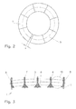
- FIG. 1 shows a segment 1 of the cage according to the invention in a perspective view.
- the segment 1 has two at a distance parallel to each other extending circumferential webs 2 and 3.
- the peripheral webs 2 and 3 are slightly bent or have a polygonal shape that follows a slight bend. In this case, the bending of the first circumferential ridge 2 has a smaller radius of curvature than the bending of the second circumferential ridge 3.
- connecting webs 4 which are oriented approximately perpendicular to the peripheral webs 2 and 3.
- a plurality of pockets 5 are formed by the peripheral webs 2 and 3 and the connecting webs 4, which serve in the illustrated embodiment, the recording conical rolling elements.
- the connecting webs 4 each have laterally molded guide surfaces 6. The guide surfaces 6 are particularly pronounced in the region of the connecting webs 4, which is arranged closer to the second peripheral web 3 than on the first peripheral web 2.
- the connecting webs 4 extend in a direction perpendicular to the plane in which the pockets 5 are arranged, so far that they stand only slightly behind the rolling elements during operation of the rolling bearing and thus do not touch the raceways of the rolling bearing.
- the cage segments 1 can be supported on the raceways when the bearing is at a standstill, and such support also takes place in the event of excessive wear in order to replace the then no longer present rolling element guide of the segments 1.
- 4 projections 7 are formed on the connecting webs. The projections 7 are not only on the in FIG. 1 visible top of the segment 1 formed, but also on the bottom.
- the first and the last connecting web 4 of the segment 1 have no guide surfaces 6 on their outwardly directed end faces 8, since no rolling element is arranged in this region, but the next segment 1. Furthermore, the end faces 8 of the connecting webs 4 are between the circumferential webs 2 and 3 concave. This ensures that adjacent segments touch each other in the region of the circumferential webs 2 and 3. In this way it can be avoided that it comes through the influence of adjacent segments 1 to each other to a deformation of the connecting webs and thus to a jamming of the rolling elements, which are arranged in the pockets 5 between the connecting webs 4.
- An essential aspect of the invention relates to the dimensioning of the segments 1 of the cage.
- This dimensioning is to be chosen such that when a gap-free stringing together of the segments 1 at their end faces 8 in a way that the cage is arranged in the rolling bearing between the adjacent end faces 8 of a last and a first segment 1 remains a gap.
- the mean extent of the gap in the circumferential direction at room temperature must be between 0.15% and 1.0% of the circumference of a circle passing centrally through the juxtaposed segments 1. This geometry is described in detail by FIG. 2 explained.
- FIG. 2 shows the cage according to the invention in a plan view, wherein the individual segments 1 are shown very schematically.
- a dashed line a centrally between the first peripheral ridge 2 and the second peripheral ridge 3 extending circle 9 is shown.
- the circle 9 extends in such a central way through the pockets 5 of the segments 1 that it penetrates rolling elements 10 inserted into the pockets 5, in each case on its axis of rotation and in the middle of its axial longitudinal extent.
- the rolling bearing is used, in which the cage is used.
- the circle 9 extends there in the middle of the axial length extension of the rolling elements 10 by their axes of rotation.
- this circle 9 On the circumference of this circle 9 is in the sizing rule of in FIG. 2 referenced with x distance of the end faces 8. Compliance with the dimensioning rule, which is based on the conditions at room temperature, is of paramount importance for proper operation. If you were to dispense with the distance x completely, ie all segments 1 would meet each other without gaps, so strong stresses would form in the cage at a temperature increase, since the plastic material of the cage significantly more thermally expands than the steel bearings made. The stresses would lead to an increase in friction, jamming or even breakage of the cage. The same applies if a lower limit of 0.15% for the ratio between the distance x and the Scope of the circle 9 is significantly below.
- the distance x is chosen to be greater than an upper limit of 1.0%, the segments 1 strongly impact against each other, especially during operation of the rolling bearing at low temperatures, causing a high level of noise and vibration, which is disturbing and cause damage to others. In addition, there is a risk that it comes through the impact to wear. In the interval according to the invention for the distance x, an optimal balance between the danger of the generation of stresses and the negative effects of an unacceptably strong impact of the segments 1 can be achieved.
- FIG. 3 shows the segment 1 in a sectional view.
- the section is guided transversely to the connecting webs 4.
- the outline of a rolling element 10 within the sectional plane is shown in one of the pockets 5.
- the rolling element 10 abuts the guide surfaces 6 of the connecting webs 4 and slightly surmounted the connecting webs 4.
- the projections 7 can be seen on the top and on the bottom of the segment.
Abstract
Description
Die Erfindung betrifft ein Segment eines Käfigs für ein Wälzlager. Aus Kunststoff gefertigte Käfige sind bereits vielfach bekannt und kommen in den verschiedensten Anwendungen zum Einsatz. Sie zeichnen sich insbesondere durch ihr geringes Gewicht, ihre kostengünstige Herstellung und vergleichsweise hohe Flexibilität aus. In der Regel sind die Kunststoff-Käfige jeweils als ein einteiliges Bauteil gefertigt. Es sind allerdings auch schon Kunststoff-Käfige bekannt geworden, die aus mehreren Segmenten zusammengesetzt sind.The invention relates to a segment of a cage for a rolling bearing. Made of plastic cages are already widely known and are used in a variety of applications. They are characterized in particular by their low weight, their cost-effective production and comparatively high flexibility. In general, the plastic cages are each made as a one-piece component. However, there are already known plastic cages, which are composed of several segments.
Ein derartiger Segmentkäfig ist aus der
Der Erfindung liegt die Aufgabe zugrunde, einen Käfig bereitzustellen, der sich für einen Einsatz bei sehr großen Wälzlagern mit verhältnismäßig kleinen Rollen eignet.The invention has for its object to provide a cage that is suitable for use in very large bearings with relatively small roles.
Diese Aufgabe wird durch die Merkmalskombination des Anspruchs 1 gelöst.This object is achieved by the combination of features of
Das erfindungsgemäße Segment eines Käfigs für ein Wälzlager ist aus Kunststoff gefertigt ist und verfügt an seinen entgegengesetzten Enden über je eine Stirnseite. Das Segment weist zwei in Umfangsrichtung verlaufende Umfangsstege und mehrere Verbindungsstege auf, die die beiden Umfangsstege miteinander verbinden und gemeinsam mit den Umfangsstegen mehrere Taschen zur Aufnahme von konischen Wälzkörpern ausbilden.The segment of a cage for a rolling bearing according to the invention is made of plastic and has at its opposite ends via a respective end face. The segment has two circumferentially extending circumferential webs and a plurality of connecting webs, which connect the two peripheral webs together and form together with the peripheral webs a plurality of pockets for receiving conical rolling elements.
Die Taschenform ermöglicht eine sichere Aufnahme der Wälzkörper und eine zuverlässige Führung des Segments an den Wälzkörpern. Ein Käfig mit derartig ausgebildeten Segmenten zeichnet sich durch seine reibungsarmen Laufeigenschaften und seine gute Montierbarkeit bei gleichzeitig geringen Kosten und geringem Gewicht aus.The pocket shape allows a secure recording of the rolling elements and a reliable guidance of the segment on the rolling elements. A cage with such trained segments is characterized by its low-friction running properties and its ease of assembly with low cost and low weight.
An den Verbindungsstegen sind vorzugsweise Führungsflächen zur Führung des Segments auf den Wälzkörpern ausgebildet. Über diese Führungsflächen können die Führungsverhältnisse präzise vorgegeben werden. Weiterhin ist es von Vorteil, wenn an den Verbindungsstegen Vorsprünge ausgebildet sind, zur Führung der Segmente auf einer Laufbahn des Wälzlagers für den Fall, dass keine ausreichende Wälzkörperführung mehr vorliegt oder zur Abstützung der Segmente auf der Laufbahn beim Stillstand des Wälzlagers. Dadurch können das Anlaufverhalten und die Notlaufeigenschaften wesentlich verbessert werden. Insbesondere kann jeder Verbindungssteg, auf seinen beiden den Laufbahnen des Wälzlagers zugewandten Seiten, jeweils wenigstens einen Vorsprung aufweisen.At the connecting webs preferably guide surfaces for guiding the segment are formed on the rolling elements. These guiding surfaces can be used to precisely specify the guiding conditions. Furthermore, it is advantageous if projections are formed on the connecting webs, for guiding the segments on a raceway of the rolling bearing in the event that there is no longer sufficient rolling element guide or for supporting the segments on the track when the rolling bearing is stationary. As a result, the startup behavior and the emergency running properties can be significantly improved. In particular, each connecting web, on its two sides facing the raceways of the rolling bearing, each have at least one projection.
Die Stirnflächen des Segments sind zwischen den Umfangsstegen vorzugsweise konkav ausgebildet. Dies hat zur Folge, dass benachbarte Segmente beim Anlaufen im Bereich der Umfangsstege aneinander liegen, so dass die aufeinander ausgeübten Kräfte jeweils in einem durch die Umfangsstege abgestützten Bereich eingeleitet werden und somit eine Verformung der Verbindungsstege und ein damit verbundenes Klemmen der Wälzkörper vermieden werden kann.The end faces of the segment are preferably concave between the peripheral webs. This has the consequence that adjacent segments lie against each other when starting in the region of the circumferential webs, so that the force exerted on each other in each case in a supported by the peripheral webs area be initiated and thus deformation of the connecting webs and an associated clamping of the rolling elements can be avoided.
Das Segment ist vorzugsweise aus Poly-Phenyl-Sulfid (PPS) oder aus Poly-Ether-Ether-Keton hergestellt. Beide Materialien zeichnen sich durch eine sehr gute Alterungsbeständigkeit und eine hohe Lebensdauer aus, so dass das erfindungsgemäße Segment über einen sehr langen Betriebszeitraum eingesetzt werden kann.The segment is preferably made of poly-phenyl-sulfide (PPS) or of poly-ether-ether-ketone. Both materials are characterized by a very good aging resistance and a long service life, so that the segment according to the invention can be used over a very long period of operation.
Die Umfangsstege können in einem Abstand parallel zueinander verlaufen. Weiterhin können die Umfangsstege leicht gebogen sein oder eine Polygonform aufweisen, die einer leichten Biegung folgt.The peripheral webs may extend at a distance parallel to each other. Furthermore, the peripheral webs may be slightly curved or polygonal in shape following a slight bend.
Die Erfindung betrifft auch einen Käfig für ein Wälzlager. Der erfindungsgemäße Käfig für ein Wälzlager ist aus Kunststoff gefertigt und weist mehrere Segmente auf, die an ihren entgegengesetzten Enden über je eine Stirnseite verfügen. Bei einer spaltfreien Aneinanderreihung der Segmente des Käfigs an ihren Stirnseiten in einer Art, wie der Käfig im Wälzlager angeordnet wird, verbleibt zwischen den benachbarten Stirnseiten eines letzten und eines ersten Segments ein Zwischenraum. Die mittlere Ausdehnung des Zwischenraums in Umfangsrichtung weist bei Raumtemperatur einen Wert auf, der zwischen 0,15 % und 1 % des Umfangs eines Kreises beträgt, der mittig durch die aneinander gereihten Segmente verläuft.The invention also relates to a cage for a rolling bearing. The cage according to the invention for a roller bearing is made of plastic and has a plurality of segments which have at their opposite ends via a respective end face. In a gap-free juxtaposition of the segments of the cage at their end faces in a manner in which the cage is arranged in the rolling bearing, a gap remains between the adjacent end faces of a last and a first segment. The mean extent of the gap in the circumferential direction at room temperature has a value which is between 0.15% and 1% of the circumference of a circle extending centrally through the juxtaposed segments.
Der erfindungsgemäße Käfig hat den Vorteil, dass ein ausreichender Raum für die verglichen mit Stahl höhere Wärmeausdehnung des Käfigs vorgesehen ist. Dieser Raum ist aber gleichzeitig klein genug bemessen, dass es nicht zu einem unvertretbaren Aufeinanderschlagen der Stirnflächen benachbarter Segmente und damit zu einer unzulässig hohen Geräuschentwicklung kommt. Insgesamt zeichnet sich der Käfig durch seine reibungsarmen Laufeigenschaften und seine gute Montierbarkeit bei gleichzeitig geringen Kosten und geringem Gewicht aus.The cage according to the invention has the advantage that sufficient space is provided for the higher thermal expansion of the cage compared with steel. At the same time, however, this space is sufficiently small that there is no unacceptable impacting of the end faces of adjacent segments and thus an inadmissibly high noise development. Overall, the cage is characterized by its low-friction running properties and its good mountability at the same time low cost and low weight.
In einem bevorzugten Ausführungsbeispiel weist jedes Segment zwei in Umfangsrichtung verlaufende Umfangsstege und wenigstens zwei Verbindungsstege auf, die die beiden Umfangsstege miteinander verbinden und die gemeinsam mit den Umfangsstegen wenigstens eine Tasche zur Aufnahme eines Wälzkörpers ausbilden. Die Taschenform ermöglicht eine sichere Aufnahme des Wälzkörpers und eine zuverlässige Führung des Käfigs am Wälzkörper. An den Verbindungsstegen sind vorzugsweise Führungsflächen zur Führung der Segmente auf den Wälzkörpern ausgebildet. Über diese Führungsflächen können die Führungsverhältnisse präzise vorgegeben werden. Weiterhin ist es von Vorteil, wenn an den Verbindungsstegen Vorsprünge ausgebildet sind, zur Führung der Segmente auf einer Laufbahn des Wälzlagers für den Fall, dass keine ausreichende Wälzkörperführung mehr vorliegt oder zur Abstützung der Segmente auf der Laufbahn beim Stillstand des Wälzlagers. Dadurch können das Anlaufverhalten und die Notlaufeigenschaften wesentlich verbessert werden. Insbesondere kann jeder Verbindungssteg, auf seinen beiden den Laufbahnen des Wälzlagers zugewandten Seiten, jeweils wenigstens einen Vorsprung aufweisen.In a preferred embodiment, each segment has two circumferentially extending circumferential webs and at least two connecting webs, which connect the two circumferential webs together and form together with the peripheral webs at least one pocket for receiving a rolling element. The pocket shape allows a secure recording of the rolling element and a reliable guidance of the cage on the rolling elements. At the connecting webs preferably guide surfaces for guiding the segments are formed on the rolling elements. These guiding surfaces can be used to precisely specify the guiding conditions. Furthermore, it is advantageous if projections are formed on the connecting webs, for guiding the segments on a raceway of the rolling bearing in the event that there is no longer sufficient rolling element guide or for supporting the segments on the track when the rolling bearing is stationary. As a result, the startup behavior and the emergency running properties can be significantly improved. In particular, each connecting web, on its two sides facing the raceways of the rolling bearing, each have at least one projection.
Die Stirnflächen der Segmente sind zwischen den Umfangsstegen vorzugsweise konkav ausgebildet. Dies hat zur Folge, dass benachbarte Segmente beim Anlaufen im Bereich der Umfangsstege aneinander liegen, so dass die aufeinander ausgeübten Kräfte jeweils in einem durch die Umfangsstege abgestützten Bereich eingeleitet werden und somit eine Verformung der Verbindungsstege und ein damit verbundenes Klemmen der Wälzkörper vermieden werden kann.The end faces of the segments are preferably concave between the peripheral webs. This has the consequence that adjacent segments abut each other during start-up in the region of the circumferential webs, so that the mutually exerted forces are each introduced in a supported by the peripheral webs area and thus deformation of the connecting webs and thus connected terminals of the rolling elements can be avoided.
Die einzelnen Segmente sind untereinander vorzugsweise nicht mechanisch verbunden und somit relativ zueinander verschiebbar, so dass eine Verformung und eine dabei auftretende erhöhte Reibung sowie ein erhöhter Verschleiß vermieden werden können.The individual segments are preferably not mechanically connected to each other and thus displaceable relative to each other, so that a deformation and an increased friction occurring as well as increased wear can be avoided.
Der Käfig ist vorzugsweise aus Poly-Phenyl-Sulfid (PPS) oder aus Poly-Ether-Ether-Keton hergestellt. Beide Materialien zeichnen sich durch eine sehr gute Alterungsbeständigkeit und eine hohe Lebensdauer aus, so dass der erfindungsgemäße Käfig über einen sehr langen Betriebszeitraum eingesetzt werden kann.The cage is preferably made of poly-phenyl-sulfide (PPS) or poly-ether-ether-ketone. Both materials are characterized by a very good aging resistance and a long service life, so that the cage according to the invention can be used over a very long period of operation.
Die Erfindung wird nachstehend anhand des in der Zeichnung dargestellten Ausführungsbeispiels erläutert.The invention will be explained below with reference to the embodiment shown in the drawing.
Es zeigen:
- Figur
- 1 ein Segment des erfindungsgemäßen Käfigs in perspektivischer Darstellung,
- Figur 2
- den erfindungsgemäßen Käfig in einer schematischen Aufsicht und
- Figur 3
- das Segment in einer Schnittdarstellung.
- figure
- 1 a perspective view of a segment of the cage according to the invention,
- FIG. 2
- the cage according to the invention in a schematic plan view and
- FIG. 3
- the segment in a sectional view.
Der erfindungsgemäße Käfig besteht aus mehreren Segmenten, die in Umfangsrichtung ohne feste Verbindung aneinandergereiht sind. Im folgenden wird ein Ausführungsbeispiel des erfindungsgemäßen Käfigs beschrieben, das für einen Einsatz in einem Kegelrollenlager vorgesehen ist, d.h. die einzelnen Segmente liegen nicht plan in einer Ebene, sondern sind alle um den gleichen Winkel zu der Ebene geneigt.The cage according to the invention consists of several segments, which are lined up in the circumferential direction without a fixed connection. In the following an embodiment of the cage according to the invention is described, which is intended for use in a tapered roller bearing, i. the individual segments are not flat in a plane, but are all inclined at the same angle to the plane.
Die Verbindungsstege 4 erstrecken sich in einer Richtung senkrecht zu der Ebene, in der die Taschen 5 angeordnet sind, so weit, dass sie beim Betrieb des Wälzlagers nur geringfügig hinter den Wälzkörpern zurückstehen und somit die Laufbahnen des Wälzlagers gerade nicht berühren. Dies führt dazu, dass sich die Käfigsegmente 1 beim Stillstand des Lagers auf die Laufbahnen abstützen können und eine derartige Abstützung auch bei einem übermäßigen Verschleiß erfolgt, um die dann nicht mehr vorhandene Wälzkörperführung der Segmente 1 zu ersetzen. Hierzu sind auf den Verbindungsstegen 4 Vorsprünge 7 ausgebildet. Die Vorsprünge 7 sind nicht nur auf der in
Der erste und der letzte Verbindungssteg 4 des Segments 1 weisen auf ihren nach außen gerichteten Stirnflächen 8 jeweils keine Führungsflächen 6 auf, da in diesem Bereich kein Wälzkörper angeordnet wird, sondern das nächste Segment 1. Weiterhin sind die Stirnflächen 8 der Verbindungsstege 4 zwischen den Umfangsstegen 2 und 3 konkav ausgebildet. Dadurch ist sichergestellt, dass einander benachbarte Segmente sich im Bereich der Umfangsstege 2 und 3 berühren. Auf diese Art und Weise kann vermieden werden, dass es durch die Einwirkung benachbarter Segmente 1 aufeinander zu einer Verformung der Verbindungsstege und damit zu einem Klemmen der Wälzkörper kommt, die in den Taschen 5 zwischen den Verbindungsstegen 4 angeordnet sind.The first and the last connecting web 4 of the
Ein wesentlicher Aspekt der Erfindung bezieht sich auf die Dimensionierung der Segmente 1 des Käfigs. Diese Dimensionierung ist so zu wählen, dass bei einer spaltfreien Aneinanderreihung der Segmente 1 an ihren Stirnseiten 8 in einer Art, wie der Käfig im Wälzlager angeordnet wird, zwischen den benachbarten Stirnseiten 8 eines letzten und eines ersten Segments 1 ein Zwischenraum verbleibt. Die mittlere Ausdehnung des Zwischenraums in Umfangsrichtung muss bei Raumtemperatur einen Wert aufweisen, der zwischen 0,15 % und 1,0 % des Umfangs eines Kreises beträgt, der mittig durch die aneinandergereihten Segmente 1 verläuft. Diese Geometrie wird im Einzelnen anhand von
- 11
- Segmentsegment
- 22
- erster Umfangsstegfirst peripheral ridge
- 33
- zweiter Umfangsstegsecond circumferential ridge
- 44
- Verbindungsstegconnecting web
- 55
- Taschebag
- 66
- Führungsflächeguide surface
- 77
- Vorsprunghead Start
- 88th
- Stirnflächeface
- 99
- Kreis durch die Mitte des KäfigsCircle through the middle of the cage
- 1010
- Wälzkörperrolling elements
Claims (8)
Applications Claiming Priority (2)
| Application Number | Priority Date | Filing Date | Title |
|---|---|---|---|
| DE10246825.7A DE10246825B4 (en) | 2002-10-08 | 2002-10-08 | Cage for a rolling bearing |
| EP03020732.8A EP1408248B1 (en) | 2002-10-08 | 2003-09-12 | Roller bearing cage |
Related Parent Applications (3)
| Application Number | Title | Priority Date | Filing Date |
|---|---|---|---|
| EP03020732.8 Division | 2003-09-12 | ||
| EP03020732.8A Division EP1408248B1 (en) | 2002-10-08 | 2003-09-12 | Roller bearing cage |
| EP03020732.8A Division-Into EP1408248B1 (en) | 2002-10-08 | 2003-09-12 | Roller bearing cage |
Publications (3)
| Publication Number | Publication Date |
|---|---|
| EP2264325A1 true EP2264325A1 (en) | 2010-12-22 |
| EP2264325B1 EP2264325B1 (en) | 2019-06-12 |
| EP2264325B2 EP2264325B2 (en) | 2023-10-25 |
Family
ID=32010374
Family Applications (2)
| Application Number | Title | Priority Date | Filing Date |
|---|---|---|---|
| EP03020732.8A Expired - Lifetime EP1408248B1 (en) | 2002-10-08 | 2003-09-12 | Roller bearing cage |
| EP10180657.8A Expired - Lifetime EP2264325B2 (en) | 2002-10-08 | 2003-09-12 | Roller bearing cage |
Family Applications Before (1)
| Application Number | Title | Priority Date | Filing Date |
|---|---|---|---|
| EP03020732.8A Expired - Lifetime EP1408248B1 (en) | 2002-10-08 | 2003-09-12 | Roller bearing cage |
Country Status (4)
| Country | Link |
|---|---|
| EP (2) | EP1408248B1 (en) |
| DE (1) | DE10246825B4 (en) |
| DK (1) | DK2264325T3 (en) |
| ES (1) | ES2744387T3 (en) |
Cited By (9)
| Publication number | Priority date | Publication date | Assignee | Title |
|---|---|---|---|---|
| EP2664807A2 (en) | 2012-05-18 | 2013-11-20 | Jtekt Corporation | Split cage for rolling bearing |
| EP2667045A1 (en) | 2012-05-22 | 2013-11-27 | Jtekt Corporation | Rolling bearing cage comprising a plurality of segments and rolling bearing with the cage |
| EP2685115A1 (en) | 2012-07-12 | 2014-01-15 | Jtekt Corporation | Jig for split cage and method of assembling rolling bearing |
| CN104154122A (en) * | 2014-08-08 | 2014-11-19 | 浙江天马轴承有限公司 | Retainer of cylindrical roller bearing |
| CN104912920A (en) * | 2015-05-31 | 2015-09-16 | 德清恒富机械有限公司 | Novel single-row roller bearing |
| DE102015219277A1 (en) | 2015-10-06 | 2017-04-06 | Schaeffler Technologies AG & Co. KG | Cage segment of a rolling bearing |
| DE102016206072A1 (en) | 2016-04-12 | 2017-10-12 | Schaeffler Technologies AG & Co. KG | Rolling bearing cage and mounting method for a rolling bearing cage |
| DE102016207034A1 (en) | 2016-04-26 | 2017-10-26 | Schaeffler Technologies AG & Co. KG | Cage segment of a cylindrical roller bearing |
| DE102016219892A1 (en) | 2016-10-12 | 2018-04-12 | Schaeffler Technologies AG & Co. KG | Cage segment of a rolling bearing |
Families Citing this family (59)
| Publication number | Priority date | Publication date | Assignee | Title |
|---|---|---|---|---|
| DE102005009980B3 (en) * | 2005-03-04 | 2006-06-14 | Aktiebolaget Skf | Antifriction bearing has inner ring along with truncated cone like inner surface, which is limited laterally by first board, second board, and outer ring with retaining segments which stand in interference with inner ring |
| EP1921333B1 (en) * | 2005-09-01 | 2013-04-03 | NTN Corporation | Roller bearing |
| DE102005054082B4 (en) * | 2005-11-12 | 2015-04-02 | Schaeffler Technologies AG & Co. KG | Cage for a rolling bearing |
| EP2388489B1 (en) | 2005-12-16 | 2014-12-17 | NTN Corporation | Roller bearing, main shaft support structure of wind-power generator, intermediate element and retainer segment |
| EP1998059B1 (en) | 2005-12-21 | 2014-06-18 | NTN Corporation | Rolling bearing, retainer segment, and main shaft support structure for wind-driven generator |
| JP4342512B2 (en) * | 2005-12-21 | 2009-10-14 | Ntn株式会社 | Rolling bearings, cage segments, and main shaft support structure for wind power generators |
| DK2461058T3 (en) | 2006-03-10 | 2015-07-13 | Ntn Toyo Bearing Co Ltd | Roller bearing, cage segment and main shaft support structure for wind powered generator |
| JP4573791B2 (en) * | 2006-03-29 | 2010-11-04 | Ntn株式会社 | Roller bearing and main shaft support structure of wind power generator |
| DE102006022951A1 (en) * | 2006-05-17 | 2007-11-22 | Schaeffler Kg | Cage segment for a cage of a rolling bearing |
| EP2511544B2 (en) | 2006-09-08 | 2021-08-18 | NTN Corporation | Retainer segment of roller bearing for supporting main shaft of wind-power generator |
| DE102007044901B4 (en) * | 2007-09-19 | 2016-02-25 | Ab Skf | Cylindrical roller bearing cage and roller bearing |
| DE102007048655A1 (en) * | 2007-10-10 | 2008-02-07 | Schaeffler Kg | Cage segment of plastic cage for anti-friction bearing, particularly for large anti-friction bearing, are arranged at front side in engaging way and on each other in impinging way in peripheral direction |
| JP5131466B2 (en) * | 2008-03-28 | 2013-01-30 | Ntn株式会社 | Roller bearing for main shaft support of wind power generator and main shaft support structure of wind power generator |
| JP2010048342A (en) * | 2008-08-21 | 2010-03-04 | Ntn Corp | Large-sized roller bearing, main shaft supporting structure of wind power generator, and rotary shaft supporting structure of tunnel boring machine |
| JP5457004B2 (en) | 2008-09-30 | 2014-04-02 | Ntn株式会社 | Method for adjusting the clearance between cage segments of a roller bearing for spindle support of a wind turbine generator |
| JP2009052746A (en) * | 2008-10-01 | 2009-03-12 | Ntn Corp | Rolling bearing, cage segment, and structure for supporting main shaft of wind power generator |
| DE102008062913A1 (en) | 2008-12-24 | 2010-07-01 | Schaeffler Technologies Gmbh & Co. Kg | segment cage |
| DE202008017091U1 (en) | 2008-12-24 | 2009-03-12 | Schaeffler Kg | segment cage |
| DE102009014779A1 (en) | 2009-03-25 | 2010-09-30 | Schaeffler Technologies Gmbh & Co. Kg | Roller bearing cage i.e. large roller bearing cage, for use in wind power plant, has spring device acting on adjacent cage segments, where play between adjacent segments is subjected to spring force produced by spring device |
| DE102009014922A1 (en) | 2009-03-25 | 2010-09-30 | Ab Skf | Greased double row rolling bearing and bearing system with such a rolling bearing and a lubricating device |
| DE102009014923C5 (en) | 2009-03-25 | 2015-07-23 | Ab Skf | Double row tapered roller bearing, in particular for supporting a rotor shaft of a wind turbine |
| DE102009015827B4 (en) | 2009-04-01 | 2023-11-02 | Ab Skf | Bearing arrangement for rotatably supporting a machine part |
| DE102009034012B4 (en) | 2009-07-21 | 2011-09-29 | Aktiebolaget Skf | Method and device for axially securing a machine element |
| DE102009037422A1 (en) | 2009-08-13 | 2011-02-17 | Schaeffler Technologies Gmbh & Co. Kg | Cage segment for a plastic cage of a rolling bearing and rolling bearing with such a cage segment |
| DE102009037420A1 (en) | 2009-08-13 | 2011-02-17 | Schaeffler Technologies Gmbh & Co. Kg | Cage segment for a plastic cage of a rolling bearing and rolling bearing with such a cage segment |
| DE102009037421A1 (en) | 2009-08-13 | 2011-02-17 | Schaeffler Technologies Gmbh & Co. Kg | Cage segment for a plastic cage of a rolling bearing and rolling bearing with such a cage segment |
| DE102009039435A1 (en) | 2009-08-31 | 2011-03-03 | Aktiebolaget Skf | Method and device for axially securing a machine element |
| CN102575712B (en) | 2009-09-11 | 2016-03-02 | 蒂姆肯公司 | For the clamp-close type retainer bridge member of rolling element bearing |
| JP4818424B2 (en) * | 2009-11-17 | 2011-11-16 | Ntn株式会社 | Wind generator main shaft support structure |
| DE102009056260A1 (en) | 2009-11-28 | 2011-06-01 | Schaeffler Technologies Gmbh & Co. Kg | Plastic cage segment for non self-roller bearing i.e. large roller bearing, has pocket formed between outer webs and connecting webs, where retaining bracket is arranged at one outer web and assembles bearing in groove of bearing rings |
| SK500272010A3 (en) * | 2010-06-26 | 2012-01-04 | Psl, A. S. | Bearing with plastic segment cage |
| DE102011087864A1 (en) | 2010-12-07 | 2012-09-06 | Aktiebolaget Skf | Cage segment of a tapered roller bearing and tapered roller bearing |
| DE102010056059A1 (en) | 2010-12-23 | 2012-06-28 | Schaeffler Technologies Gmbh & Co. Kg | Rolling bearing cage and roller bearings |
| CN102562812B (en) * | 2010-12-29 | 2014-07-30 | 上海联合滚动轴承有限公司 | Retainer on large wind-power double-row tapered roller bearing |
| CN103089817A (en) * | 2011-10-27 | 2013-05-08 | 洛阳双龙塑料制品有限公司 | Sectional type retainer for spindle bearing of direct-driven wind generating set |
| DE102011085356A1 (en) | 2011-10-28 | 2013-05-02 | Schaeffler Technologies AG & Co. KG | Bearing set e.g. ball bearing set has rolling element that is arranged between two adjacent retainer segments so that rolling element is contacted with retainer segments |
| EP2610511A1 (en) | 2011-12-28 | 2013-07-03 | Siemens Aktiengesellschaft | Cage and rolling element bearing |
| EP2610512A1 (en) | 2011-12-28 | 2013-07-03 | Siemens Aktiengesellschaft | Rolling element bearing |
| EP2610508A1 (en) | 2011-12-28 | 2013-07-03 | Siemens Aktiengesellschaft | Rolling element bearing |
| DE102012202522A1 (en) | 2012-02-20 | 2013-08-22 | Schaeffler Technologies AG & Co. KG | Sensor bearing, has outer ring coaxially surrounding inner ring, and circular cage distributing pockets uniformly in circumferential direction, where total number of pockets and total number of rolling bodies satisfy specific equation |
| DE102012207529A1 (en) | 2012-05-07 | 2013-11-07 | Aktiebolaget Skf | Cage segment of a tapered roller bearing and tapered roller bearing |
| JP2014139474A (en) | 2012-12-21 | 2014-07-31 | Nsk Ltd | Rolling bearing |
| EP3404274B1 (en) | 2012-12-25 | 2020-04-08 | NSK Ltd. | Tapered roller bearing |
| US20160040716A1 (en) | 2013-04-04 | 2016-02-11 | Nsk Ltd. | Resin cage for tapered roller bearing and tapered roller bearing including the resin cage |
| JP6055357B2 (en) * | 2013-04-04 | 2016-12-27 | 日本精工株式会社 | Resin cage for tapered roller bearings |
| WO2014167107A1 (en) | 2013-04-11 | 2014-10-16 | Aktiebolaget Skf | Rolling bearing with rolling bodies disposed in a plurality of cage segments |
| DE102013218286A1 (en) | 2013-09-12 | 2015-03-12 | Schaeffler Technologies AG & Co. KG | Cage for a rolling bearing and associated rolling bearing |
| FR3013087B1 (en) * | 2013-11-14 | 2016-05-06 | Skf Aerospace France | MECHANICAL BEARING |
| JP2015102153A (en) * | 2013-11-25 | 2015-06-04 | 株式会社ジェイテクト | Split cage and roller bearing |
| DE102014203148A1 (en) | 2014-02-21 | 2015-08-27 | Schaeffler Technologies AG & Co. KG | cage segment |
| DE102014207931B4 (en) | 2014-04-28 | 2019-06-19 | Aktiebolaget Skf | Rolling bearings with cage segments with dampers |
| USD771166S1 (en) | 2014-06-19 | 2016-11-08 | Nsk Ltd. | Tapered roller bearing cage |
| DE102014220649A1 (en) * | 2014-10-13 | 2016-04-14 | Schaeffler Technologies AG & Co. KG | Cage module and roller bearings with a cage constructed from these cage modules |
| CN104565023A (en) * | 2014-12-30 | 2015-04-29 | 瓦房店轴承集团有限责任公司 | Large-megawatt double-row tapered roller bearing provided with retainers self-guided by rolling elements |
| DE102015200381A1 (en) | 2015-01-14 | 2016-07-14 | Schaeffler Technologies AG & Co. KG | Cage segment of a rolling bearing |
| DE102015205256A1 (en) | 2015-03-24 | 2016-09-29 | Schaeffler Technologies AG & Co. KG | Cage for a rolling bearing and method for adjusting a final play of a cage in a rolling bearing |
| DE102015206533A1 (en) | 2015-04-13 | 2016-10-13 | Schaeffler Technologies AG & Co. KG | Cage segment of a cage of a rolling bearing and cage of a rolling bearing |
| CN108361281B (en) * | 2017-01-26 | 2021-01-01 | 斯凯孚公司 | Cage segment, segmented cage and bearing |
| DE102018105242B3 (en) * | 2018-03-07 | 2019-06-13 | Sumitomo (Shi) Cyclo Drive Germany Gmbh | RADIAL SLANT ROLLENLAGER |
Citations (5)
| Publication number | Priority date | Publication date | Assignee | Title |
|---|---|---|---|---|
| DE1026577B (en) * | 1956-06-06 | 1958-03-20 | Skf Kugellagerfabriken Gmbh | Cage for radial roller bearings |
| DE7914789U1 (en) * | 1979-08-23 | Kugelfischer Georg Schaefer & Co, 8720 Schweinfurt | Rolling bearings, preferably for large cylindrical roller bearings | |
| DE8420133U1 (en) | 1984-10-31 | Skf Kugellagerfabriken Gmbh, 8720 Schweinfurt | Segment cage for roller bearings, especially for cylindrical roller bearings | |
| DE3509190A1 (en) * | 1985-03-14 | 1986-09-18 | FAG Kugelfischer Georg Schäfer KGaA, 8720 Schweinfurt | Segmental cage for roller bearings |
| US5015105A (en) * | 1989-04-07 | 1991-05-14 | Koyo Seiko Co., Ltd. | Crown-shaped cage for a radial bearing |
Family Cites Families (13)
| Publication number | Priority date | Publication date | Assignee | Title |
|---|---|---|---|---|
| DE7432281U (en) * | 1975-01-16 | Duerkoppwerke Gmbh | Link cage for axial roller bearings | |
| DE840175C (en) * | 1943-07-06 | 1952-05-29 | Ver Kugellagerfabriken Ag | Cage for ring bearings |
| NL109636C (en) | 1958-01-22 | 1900-01-01 | ||
| DE1866122U (en) * | 1962-11-29 | 1963-01-24 | Rothe Erde Eisenwerk | PLASTIC CAGE FOR ROLLER BEARING. |
| FR2224015A1 (en) * | 1973-03-27 | 1974-10-25 | Rks | |
| DE3113911C2 (en) * | 1981-04-07 | 1984-08-16 | FAG Kugelfischer Georg Schäfer KGaA, 8720 Schweinfurt | Segment cage |
| DE3115780C2 (en) * | 1981-04-18 | 1984-02-09 | FAG Kugelfischer Georg Schäfer KGaA, 8720 Schweinfurt | Segment cage for roller bearings |
| DE3120265C2 (en) * | 1981-05-21 | 1983-05-19 | FAG Kugelfischer Georg Schäfer & Co, 8720 Schweinfurt | Segment cage for a crossed roller bearing |
| DE3245332C2 (en) * | 1982-12-08 | 1985-06-27 | FAG Kugelfischer Georg Schäfer KGaA, 8720 Schweinfurt | Segment cage for roller bearings |
| DE8607236U1 (en) * | 1986-03-15 | 1986-05-07 | SKF GmbH, 8720 Schweinfurt | Segment cage |
| JPH053644A (en) | 1991-06-27 | 1993-01-08 | Fuji Electric Co Ltd | Vertical type full-enclosed fan-cooled rotary electric machine equipped with dripproof cover |
| JPH0519652U (en) * | 1991-06-28 | 1993-03-12 | エヌテイエヌ株式会社 | Needle-shaped roller bearings with split cage |
| DE20005228U1 (en) | 1999-08-12 | 2000-07-06 | Skf Gmbh | Cage for a tapered roller bearing |
-
2002
- 2002-10-08 DE DE10246825.7A patent/DE10246825B4/en not_active Expired - Lifetime
-
2003
- 2003-09-12 ES ES10180657T patent/ES2744387T3/en not_active Expired - Lifetime
- 2003-09-12 EP EP03020732.8A patent/EP1408248B1/en not_active Expired - Lifetime
- 2003-09-12 DK DK10180657.8T patent/DK2264325T3/en active
- 2003-09-12 EP EP10180657.8A patent/EP2264325B2/en not_active Expired - Lifetime
Patent Citations (5)
| Publication number | Priority date | Publication date | Assignee | Title |
|---|---|---|---|---|
| DE7914789U1 (en) * | 1979-08-23 | Kugelfischer Georg Schaefer & Co, 8720 Schweinfurt | Rolling bearings, preferably for large cylindrical roller bearings | |
| DE8420133U1 (en) | 1984-10-31 | Skf Kugellagerfabriken Gmbh, 8720 Schweinfurt | Segment cage for roller bearings, especially for cylindrical roller bearings | |
| DE1026577B (en) * | 1956-06-06 | 1958-03-20 | Skf Kugellagerfabriken Gmbh | Cage for radial roller bearings |
| DE3509190A1 (en) * | 1985-03-14 | 1986-09-18 | FAG Kugelfischer Georg Schäfer KGaA, 8720 Schweinfurt | Segmental cage for roller bearings |
| US5015105A (en) * | 1989-04-07 | 1991-05-14 | Koyo Seiko Co., Ltd. | Crown-shaped cage for a radial bearing |
Cited By (20)
| Publication number | Priority date | Publication date | Assignee | Title |
|---|---|---|---|---|
| EP2664807A2 (en) | 2012-05-18 | 2013-11-20 | Jtekt Corporation | Split cage for rolling bearing |
| EP2664807A3 (en) * | 2012-05-18 | 2013-12-04 | Jtekt Corporation | Split cage for rolling bearing |
| US8770853B2 (en) | 2012-05-18 | 2014-07-08 | Jtekt Corporation | Split cage for rolling bearing |
| EP2667045A1 (en) | 2012-05-22 | 2013-11-27 | Jtekt Corporation | Rolling bearing cage comprising a plurality of segments and rolling bearing with the cage |
| US8851761B2 (en) | 2012-05-22 | 2014-10-07 | Jtekt Corporation | Split cage for rolling bearing and rolling bearing using the split cage |
| EP2685115A1 (en) | 2012-07-12 | 2014-01-15 | Jtekt Corporation | Jig for split cage and method of assembling rolling bearing |
| CN104154122A (en) * | 2014-08-08 | 2014-11-19 | 浙江天马轴承有限公司 | Retainer of cylindrical roller bearing |
| CN104154122B (en) * | 2014-08-08 | 2016-08-17 | 浙江天马轴承有限公司 | A kind of retainer of cylinder roller bearing |
| CN104912920A (en) * | 2015-05-31 | 2015-09-16 | 德清恒富机械有限公司 | Novel single-row roller bearing |
| CN104912920B (en) * | 2015-05-31 | 2017-05-31 | 德清恒富机械有限公司 | single-row roller bearing |
| WO2017059850A1 (en) | 2015-10-06 | 2017-04-13 | Schaeffler Technologies AG & Co. KG | Cage segment of a rolling bearing |
| DE102015219277A1 (en) | 2015-10-06 | 2017-04-06 | Schaeffler Technologies AG & Co. KG | Cage segment of a rolling bearing |
| US10458473B2 (en) | 2015-10-06 | 2019-10-29 | Schaeffler Technologies AG & Co. KG | Cage segment of a rolling bearing |
| DE102016206072A1 (en) | 2016-04-12 | 2017-10-12 | Schaeffler Technologies AG & Co. KG | Rolling bearing cage and mounting method for a rolling bearing cage |
| WO2017178004A1 (en) | 2016-04-12 | 2017-10-19 | Schaeffler Technologies AG & Co. KG | Rolling-bearing cage and assembly method for a rolling-bearing cage |
| DE102016206072B4 (en) * | 2016-04-12 | 2018-02-22 | Schaeffler Technologies AG & Co. KG | Rolling bearing cage |
| DE102016207034A1 (en) | 2016-04-26 | 2017-10-26 | Schaeffler Technologies AG & Co. KG | Cage segment of a cylindrical roller bearing |
| WO2017186210A1 (en) | 2016-04-26 | 2017-11-02 | Schaeffler Technologies AG & Co. KG | Cage segment of a cylindrical roller bearing |
| DE102016219892A1 (en) | 2016-10-12 | 2018-04-12 | Schaeffler Technologies AG & Co. KG | Cage segment of a rolling bearing |
| WO2018068779A1 (en) | 2016-10-12 | 2018-04-19 | Schaeffler Technologies AG & Co. KG | Cage segment of a rolling bearing |
Also Published As
| Publication number | Publication date |
|---|---|
| DE10246825B4 (en) | 2019-02-14 |
| EP2264325B1 (en) | 2019-06-12 |
| DE10246825A1 (en) | 2004-04-22 |
| EP1408248A2 (en) | 2004-04-14 |
| EP1408248B1 (en) | 2014-08-20 |
| EP2264325B2 (en) | 2023-10-25 |
| EP1408248A3 (en) | 2006-04-19 |
| ES2744387T3 (en) | 2020-02-24 |
| DK2264325T3 (en) | 2019-09-16 |
Similar Documents
| Publication | Publication Date | Title |
|---|---|---|
| EP1408248B1 (en) | Roller bearing cage | |
| DE102015201257B3 (en) | Ball screw and associated electromechanical actuator | |
| EP1977125B1 (en) | Multi-row angular contact roller bearing with spherical rollers | |
| DE102009012241A1 (en) | Rolling bearing with segmented cage | |
| DE102005034739A1 (en) | Storage of a pivoting lever | |
| DE3221733C2 (en) | ||
| EP0222692A2 (en) | Rolling bearing | |
| DE102011085716A1 (en) | Radial cage e.g. needle bearing cage for cylindrical rolling elements, has profile rollers and side rings that are arranged, such that material thicknesses of rollers are smaller than thickness of side portions of axial webs | |
| EP3810944B1 (en) | Thrust rolling bearing | |
| DE3623310C2 (en) | ||
| DE102008026340A1 (en) | Roller bearing i.e. self-aligning roller bearing, has rollers forming insulated contact zone with inner track surface in central mantle surface areas and forming two insulated contact zones with outer track surface | |
| DE102005033356A1 (en) | Radial rolling bearing has rolling bodies in bearing cage between outer and inner bearing rings with an elastic spring ring of spring steel band with high modulus of elasticity pressing bodies against tracks | |
| WO2011117076A1 (en) | Spacer for spacing apart rolling elements in a row of rolling elements and rolling-contact bearing having the spacer | |
| DE102015205256A1 (en) | Cage for a rolling bearing and method for adjusting a final play of a cage in a rolling bearing | |
| DE102006051643B4 (en) | Tandem angular contact bearings | |
| DE102011085713A1 (en) | Radial cage for cylindrical rolling body, particularly needle ring cage, has two side rings defining axial extension of radial cage and multiple profiled axial bars connected with each other at outer diameters of side rings | |
| DE10315219A1 (en) | Ball screw has intermediate elements with spring sections elastically constructed in axial direction acting against respectively adjacent balls and formed around central non-sprung section | |
| DE3911914C2 (en) | Rolling bearing arrangement | |
| DE102017115906A1 (en) | Bearing cage for roller bearings and roller bearings | |
| WO2008061503A1 (en) | Radial roller bearing, in particular for storing shafts in wind turbine transmissions | |
| DE102016212200A1 (en) | Cylindrical roller bearing and roller bearing cage for it | |
| DE102018202276B4 (en) | Liquid pump with vibration damping element | |
| DE202020102203U1 (en) | Rolling cage | |
| DE102022206813A1 (en) | Circlip arrangement with a radially circumferentially closed circlip for axially prestressing a machine part arranged on a shaft | |
| DE102012021504A1 (en) | Annular spring element for application of frictional forces and radial spring forces by deformation, and for use in rolling element of tripod joint, has outer edge which is formed by outer surface and one of side surfaces |
Legal Events
| Date | Code | Title | Description |
|---|---|---|---|
| PUAI | Public reference made under article 153(3) epc to a published international application that has entered the european phase |
Free format text: ORIGINAL CODE: 0009012 |
|
| AC | Divisional application: reference to earlier application |
Ref document number: 1408248 Country of ref document: EP Kind code of ref document: P |
|
| AK | Designated contracting states |
Kind code of ref document: A1 Designated state(s): AT BE BG CH CY CZ DE DK EE ES FI FR GB GR HU IE IT LI LU MC NL PT RO SE SI SK TR |
|
| 17P | Request for examination filed |
Effective date: 20110622 |
|
| 17Q | First examination report despatched |
Effective date: 20121128 |
|
| STAA | Information on the status of an ep patent application or granted ep patent |
Free format text: STATUS: EXAMINATION IS IN PROGRESS |
|
| GRAP | Despatch of communication of intention to grant a patent |
Free format text: ORIGINAL CODE: EPIDOSNIGR1 |
|
| STAA | Information on the status of an ep patent application or granted ep patent |
Free format text: STATUS: GRANT OF PATENT IS INTENDED |
|
| INTG | Intention to grant announced |
Effective date: 20190102 |
|
| GRAS | Grant fee paid |
Free format text: ORIGINAL CODE: EPIDOSNIGR3 |
|
| GRAA | (expected) grant |
Free format text: ORIGINAL CODE: 0009210 |
|
| STAA | Information on the status of an ep patent application or granted ep patent |
Free format text: STATUS: THE PATENT HAS BEEN GRANTED |
|
| AC | Divisional application: reference to earlier application |
Ref document number: 1408248 Country of ref document: EP Kind code of ref document: P |
|
| AK | Designated contracting states |
Kind code of ref document: B1 Designated state(s): AT BE BG CH CY CZ DE DK EE ES FI FR GB GR HU IE IT LI LU MC NL PT RO SE SI SK TR |
|
| REG | Reference to a national code |
Ref country code: GB Ref legal event code: FG4D Free format text: NOT ENGLISH |
|
| REG | Reference to a national code |
Ref country code: CH Ref legal event code: EP |
|
| REG | Reference to a national code |
Ref country code: AT Ref legal event code: REF Ref document number: 1142937 Country of ref document: AT Kind code of ref document: T Effective date: 20190615 |
|
| REG | Reference to a national code |
Ref country code: DE Ref legal event code: R096 Ref document number: 50315848 Country of ref document: DE |
|
| REG | Reference to a national code |
Ref country code: IE Ref legal event code: FG4D Free format text: LANGUAGE OF EP DOCUMENT: GERMAN |
|
| REG | Reference to a national code |
Ref country code: DK Ref legal event code: T3 Effective date: 20190912 |
|
| REG | Reference to a national code |
Ref country code: NL Ref legal event code: MP Effective date: 20190612 |
|
| PG25 | Lapsed in a contracting state [announced via postgrant information from national office to epo] |
Ref country code: SE Free format text: LAPSE BECAUSE OF FAILURE TO SUBMIT A TRANSLATION OF THE DESCRIPTION OR TO PAY THE FEE WITHIN THE PRESCRIBED TIME-LIMIT Effective date: 20190612 Ref country code: FI Free format text: LAPSE BECAUSE OF FAILURE TO SUBMIT A TRANSLATION OF THE DESCRIPTION OR TO PAY THE FEE WITHIN THE PRESCRIBED TIME-LIMIT Effective date: 20190612 |
|
| PG25 | Lapsed in a contracting state [announced via postgrant information from national office to epo] |
Ref country code: BG Free format text: LAPSE BECAUSE OF FAILURE TO SUBMIT A TRANSLATION OF THE DESCRIPTION OR TO PAY THE FEE WITHIN THE PRESCRIBED TIME-LIMIT Effective date: 20190912 Ref country code: GR Free format text: LAPSE BECAUSE OF FAILURE TO SUBMIT A TRANSLATION OF THE DESCRIPTION OR TO PAY THE FEE WITHIN THE PRESCRIBED TIME-LIMIT Effective date: 20190913 |
|
| PG25 | Lapsed in a contracting state [announced via postgrant information from national office to epo] |
Ref country code: NL Free format text: LAPSE BECAUSE OF FAILURE TO SUBMIT A TRANSLATION OF THE DESCRIPTION OR TO PAY THE FEE WITHIN THE PRESCRIBED TIME-LIMIT Effective date: 20190612 Ref country code: CZ Free format text: LAPSE BECAUSE OF FAILURE TO SUBMIT A TRANSLATION OF THE DESCRIPTION OR TO PAY THE FEE WITHIN THE PRESCRIBED TIME-LIMIT Effective date: 20190612 Ref country code: RO Free format text: LAPSE BECAUSE OF FAILURE TO SUBMIT A TRANSLATION OF THE DESCRIPTION OR TO PAY THE FEE WITHIN THE PRESCRIBED TIME-LIMIT Effective date: 20190612 Ref country code: EE Free format text: LAPSE BECAUSE OF FAILURE TO SUBMIT A TRANSLATION OF THE DESCRIPTION OR TO PAY THE FEE WITHIN THE PRESCRIBED TIME-LIMIT Effective date: 20190612 Ref country code: PT Free format text: LAPSE BECAUSE OF FAILURE TO SUBMIT A TRANSLATION OF THE DESCRIPTION OR TO PAY THE FEE WITHIN THE PRESCRIBED TIME-LIMIT Effective date: 20191014 Ref country code: SK Free format text: LAPSE BECAUSE OF FAILURE TO SUBMIT A TRANSLATION OF THE DESCRIPTION OR TO PAY THE FEE WITHIN THE PRESCRIBED TIME-LIMIT Effective date: 20190612 |
|
| REG | Reference to a national code |
Ref country code: ES Ref legal event code: FG2A Ref document number: 2744387 Country of ref document: ES Kind code of ref document: T3 Effective date: 20200224 |
|
| PG25 | Lapsed in a contracting state [announced via postgrant information from national office to epo] |
Ref country code: IT Free format text: LAPSE BECAUSE OF FAILURE TO SUBMIT A TRANSLATION OF THE DESCRIPTION OR TO PAY THE FEE WITHIN THE PRESCRIBED TIME-LIMIT Effective date: 20190612 |
|
| REG | Reference to a national code |
Ref country code: DE Ref legal event code: R026 Ref document number: 50315848 Country of ref document: DE |
|
| PLBI | Opposition filed |
Free format text: ORIGINAL CODE: 0009260 |
|
| PLAX | Notice of opposition and request to file observation + time limit sent |
Free format text: ORIGINAL CODE: EPIDOSNOBS2 |
|
| PG25 | Lapsed in a contracting state [announced via postgrant information from national office to epo] |
Ref country code: TR Free format text: LAPSE BECAUSE OF FAILURE TO SUBMIT A TRANSLATION OF THE DESCRIPTION OR TO PAY THE FEE WITHIN THE PRESCRIBED TIME-LIMIT Effective date: 20190612 |
|
| 26 | Opposition filed |
Opponent name: SCHAEFFLER TECHNOLOGIES AG & CO. KG Effective date: 20200311 |
|
| PG25 | Lapsed in a contracting state [announced via postgrant information from national office to epo] |
Ref country code: SI Free format text: LAPSE BECAUSE OF FAILURE TO SUBMIT A TRANSLATION OF THE DESCRIPTION OR TO PAY THE FEE WITHIN THE PRESCRIBED TIME-LIMIT Effective date: 20190612 Ref country code: MC Free format text: LAPSE BECAUSE OF FAILURE TO SUBMIT A TRANSLATION OF THE DESCRIPTION OR TO PAY THE FEE WITHIN THE PRESCRIBED TIME-LIMIT Effective date: 20190612 |
|
| REG | Reference to a national code |
Ref country code: CH Ref legal event code: PL |
|
| PLBB | Reply of patent proprietor to notice(s) of opposition received |
Free format text: ORIGINAL CODE: EPIDOSNOBS3 |
|
| PG25 | Lapsed in a contracting state [announced via postgrant information from national office to epo] |
Ref country code: IE Free format text: LAPSE BECAUSE OF NON-PAYMENT OF DUE FEES Effective date: 20190912 Ref country code: LU Free format text: LAPSE BECAUSE OF NON-PAYMENT OF DUE FEES Effective date: 20190912 Ref country code: LI Free format text: LAPSE BECAUSE OF NON-PAYMENT OF DUE FEES Effective date: 20190930 Ref country code: CH Free format text: LAPSE BECAUSE OF NON-PAYMENT OF DUE FEES Effective date: 20190930 |
|
| REG | Reference to a national code |
Ref country code: BE Ref legal event code: MM Effective date: 20190930 |
|
| PG25 | Lapsed in a contracting state [announced via postgrant information from national office to epo] |
Ref country code: BE Free format text: LAPSE BECAUSE OF NON-PAYMENT OF DUE FEES Effective date: 20190930 |
|
| REG | Reference to a national code |
Ref country code: AT Ref legal event code: MM01 Ref document number: 1142937 Country of ref document: AT Kind code of ref document: T Effective date: 20190912 |
|
| PG25 | Lapsed in a contracting state [announced via postgrant information from national office to epo] |
Ref country code: AT Free format text: LAPSE BECAUSE OF NON-PAYMENT OF DUE FEES Effective date: 20190912 |
|
| PG25 | Lapsed in a contracting state [announced via postgrant information from national office to epo] |
Ref country code: CY Free format text: LAPSE BECAUSE OF FAILURE TO SUBMIT A TRANSLATION OF THE DESCRIPTION OR TO PAY THE FEE WITHIN THE PRESCRIBED TIME-LIMIT Effective date: 20190612 |
|
| PG25 | Lapsed in a contracting state [announced via postgrant information from national office to epo] |
Ref country code: HU Free format text: LAPSE BECAUSE OF FAILURE TO SUBMIT A TRANSLATION OF THE DESCRIPTION OR TO PAY THE FEE WITHIN THE PRESCRIBED TIME-LIMIT; INVALID AB INITIO Effective date: 20030912 |
|
| PGFP | Annual fee paid to national office [announced via postgrant information from national office to epo] |
Ref country code: GB Payment date: 20220920 Year of fee payment: 20 Ref country code: DK Payment date: 20220923 Year of fee payment: 20 Ref country code: DE Payment date: 20220927 Year of fee payment: 20 |
|
| PGFP | Annual fee paid to national office [announced via postgrant information from national office to epo] |
Ref country code: FR Payment date: 20220927 Year of fee payment: 20 |
|
| REG | Reference to a national code |
Ref country code: CH Ref legal event code: PK Free format text: BERICHTIGUNGEN |
|
| RIC2 | Information provided on ipc code assigned after grant |
Ipc: B62K 21/12 20060101ALI20221215BHEP Ipc: B62J 43/28 20200101AFI20221215BHEP |
|
| PGFP | Annual fee paid to national office [announced via postgrant information from national office to epo] |
Ref country code: ES Payment date: 20221013 Year of fee payment: 20 |
|
| P01 | Opt-out of the competence of the unified patent court (upc) registered |
Effective date: 20230513 |
|
| REG | Reference to a national code |
Ref country code: DE Ref legal event code: R071 Ref document number: 50315848 Country of ref document: DE |
|
| REG | Reference to a national code |
Ref country code: DK Ref legal event code: EUP Expiry date: 20230912 |
|
| PUAH | Patent maintained in amended form |
Free format text: ORIGINAL CODE: 0009272 |
|
| STAA | Information on the status of an ep patent application or granted ep patent |
Free format text: STATUS: PATENT MAINTAINED AS AMENDED |
|
| REG | Reference to a national code |
Ref country code: ES Ref legal event code: FD2A Effective date: 20230929 |
|
| REG | Reference to a national code |
Ref country code: GB Ref legal event code: PE20 Expiry date: 20230911 |
|
| 27A | Patent maintained in amended form |
Effective date: 20231025 |
|
| AK | Designated contracting states |
Kind code of ref document: B2 Designated state(s): AT BE BG CH CY CZ DE DK EE ES FI FR GB GR HU IE IT LI LU MC NL PT RO SE SI SK TR |
|
| REG | Reference to a national code |
Ref country code: DE Ref legal event code: R102 Ref document number: 50315848 Country of ref document: DE |
|
| PG25 | Lapsed in a contracting state [announced via postgrant information from national office to epo] |
Ref country code: GB Free format text: LAPSE BECAUSE OF EXPIRATION OF PROTECTION Effective date: 20230911 Ref country code: ES Free format text: LAPSE BECAUSE OF EXPIRATION OF PROTECTION Effective date: 20230913 |