EP2263613A1 - Composant prothétique glénoïdien et jeu d'au moins deux de ces composants - Google Patents
Composant prothétique glénoïdien et jeu d'au moins deux de ces composants Download PDFInfo
- Publication number
- EP2263613A1 EP2263613A1 EP10166096A EP10166096A EP2263613A1 EP 2263613 A1 EP2263613 A1 EP 2263613A1 EP 10166096 A EP10166096 A EP 10166096A EP 10166096 A EP10166096 A EP 10166096A EP 2263613 A1 EP2263613 A1 EP 2263613A1
- Authority
- EP
- European Patent Office
- Prior art keywords
- humeral head
- glenoid
- face
- support body
- component according
- Prior art date
- Legal status (The legal status is an assumption and is not a legal conclusion. Google has not performed a legal analysis and makes no representation as to the accuracy of the status listed.)
- Granted
Links
- 241001653121 Glenoides Species 0.000 title claims description 56
- 230000002093 peripheral effect Effects 0.000 claims abstract description 43
- 210000004095 humeral head Anatomy 0.000 claims abstract description 41
- 210000000988 bone and bone Anatomy 0.000 claims description 14
- 230000000069 prophylactic effect Effects 0.000 claims 1
- 239000000463 material Substances 0.000 description 9
- 230000006399 behavior Effects 0.000 description 6
- 239000011324 bead Substances 0.000 description 5
- 230000005489 elastic deformation Effects 0.000 description 3
- 210000002758 humerus Anatomy 0.000 description 3
- 238000002513 implantation Methods 0.000 description 3
- 210000000323 shoulder joint Anatomy 0.000 description 3
- 230000003313 weakening effect Effects 0.000 description 3
- 239000004696 Poly ether ether ketone Substances 0.000 description 2
- 230000000694 effects Effects 0.000 description 2
- 239000013013 elastic material Substances 0.000 description 2
- 229920002530 polyetherether ketone Polymers 0.000 description 2
- 210000001991 scapula Anatomy 0.000 description 2
- 241000323773 Glenus Species 0.000 description 1
- 235000014443 Pyrus communis Nutrition 0.000 description 1
- 210000003484 anatomy Anatomy 0.000 description 1
- 238000013459 approach Methods 0.000 description 1
- 239000004568 cement Substances 0.000 description 1
- 239000011248 coating agent Substances 0.000 description 1
- 238000000576 coating method Methods 0.000 description 1
- 230000001419 dependent effect Effects 0.000 description 1
- 229920001903 high density polyethylene Polymers 0.000 description 1
- 239000004700 high-density polyethylene Substances 0.000 description 1
- 229910052588 hydroxylapatite Inorganic materials 0.000 description 1
- 230000005923 long-lasting effect Effects 0.000 description 1
- 229910001092 metal group alloy Inorganic materials 0.000 description 1
- 238000010883 osseointegration Methods 0.000 description 1
- 230000001575 pathological effect Effects 0.000 description 1
- XYJRXVWERLGGKC-UHFFFAOYSA-D pentacalcium;hydroxide;triphosphate Chemical compound [OH-].[Ca+2].[Ca+2].[Ca+2].[Ca+2].[Ca+2].[O-]P([O-])([O-])=O.[O-]P([O-])([O-])=O.[O-]P([O-])([O-])=O XYJRXVWERLGGKC-UHFFFAOYSA-D 0.000 description 1
- 229920002635 polyurethane Polymers 0.000 description 1
- 239000004814 polyurethane Substances 0.000 description 1
- -1 pyrocarbon Polymers 0.000 description 1
- 238000004088 simulation Methods 0.000 description 1
- 238000001356 surgical procedure Methods 0.000 description 1
Images


Classifications
-
- A—HUMAN NECESSITIES
- A61—MEDICAL OR VETERINARY SCIENCE; HYGIENE
- A61F—FILTERS IMPLANTABLE INTO BLOOD VESSELS; PROSTHESES; DEVICES PROVIDING PATENCY TO, OR PREVENTING COLLAPSING OF, TUBULAR STRUCTURES OF THE BODY, e.g. STENTS; ORTHOPAEDIC, NURSING OR CONTRACEPTIVE DEVICES; FOMENTATION; TREATMENT OR PROTECTION OF EYES OR EARS; BANDAGES, DRESSINGS OR ABSORBENT PADS; FIRST-AID KITS
- A61F2/00—Filters implantable into blood vessels; Prostheses, i.e. artificial substitutes or replacements for parts of the body; Appliances for connecting them with the body; Devices providing patency to, or preventing collapsing of, tubular structures of the body, e.g. stents
- A61F2/02—Prostheses implantable into the body
- A61F2/30—Joints
- A61F2/40—Joints for shoulders
- A61F2/4081—Glenoid components, e.g. cups
-
- A—HUMAN NECESSITIES
- A61—MEDICAL OR VETERINARY SCIENCE; HYGIENE
- A61F—FILTERS IMPLANTABLE INTO BLOOD VESSELS; PROSTHESES; DEVICES PROVIDING PATENCY TO, OR PREVENTING COLLAPSING OF, TUBULAR STRUCTURES OF THE BODY, e.g. STENTS; ORTHOPAEDIC, NURSING OR CONTRACEPTIVE DEVICES; FOMENTATION; TREATMENT OR PROTECTION OF EYES OR EARS; BANDAGES, DRESSINGS OR ABSORBENT PADS; FIRST-AID KITS
- A61F2/00—Filters implantable into blood vessels; Prostheses, i.e. artificial substitutes or replacements for parts of the body; Appliances for connecting them with the body; Devices providing patency to, or preventing collapsing of, tubular structures of the body, e.g. stents
- A61F2/02—Prostheses implantable into the body
- A61F2/30—Joints
- A61F2002/30001—Additional features of subject-matter classified in A61F2/28, A61F2/30 and subgroups thereof
- A61F2002/30108—Shapes
- A61F2002/3011—Cross-sections or two-dimensional shapes
-
- A—HUMAN NECESSITIES
- A61—MEDICAL OR VETERINARY SCIENCE; HYGIENE
- A61F—FILTERS IMPLANTABLE INTO BLOOD VESSELS; PROSTHESES; DEVICES PROVIDING PATENCY TO, OR PREVENTING COLLAPSING OF, TUBULAR STRUCTURES OF THE BODY, e.g. STENTS; ORTHOPAEDIC, NURSING OR CONTRACEPTIVE DEVICES; FOMENTATION; TREATMENT OR PROTECTION OF EYES OR EARS; BANDAGES, DRESSINGS OR ABSORBENT PADS; FIRST-AID KITS
- A61F2/00—Filters implantable into blood vessels; Prostheses, i.e. artificial substitutes or replacements for parts of the body; Appliances for connecting them with the body; Devices providing patency to, or preventing collapsing of, tubular structures of the body, e.g. stents
- A61F2/02—Prostheses implantable into the body
- A61F2/30—Joints
- A61F2002/30001—Additional features of subject-matter classified in A61F2/28, A61F2/30 and subgroups thereof
- A61F2002/30316—The prosthesis having different structural features at different locations within the same prosthesis; Connections between prosthetic parts; Special structural features of bone or joint prostheses not otherwise provided for
- A61F2002/30535—Special structural features of bone or joint prostheses not otherwise provided for
- A61F2002/30565—Special structural features of bone or joint prostheses not otherwise provided for having spring elements
-
- A—HUMAN NECESSITIES
- A61—MEDICAL OR VETERINARY SCIENCE; HYGIENE
- A61F—FILTERS IMPLANTABLE INTO BLOOD VESSELS; PROSTHESES; DEVICES PROVIDING PATENCY TO, OR PREVENTING COLLAPSING OF, TUBULAR STRUCTURES OF THE BODY, e.g. STENTS; ORTHOPAEDIC, NURSING OR CONTRACEPTIVE DEVICES; FOMENTATION; TREATMENT OR PROTECTION OF EYES OR EARS; BANDAGES, DRESSINGS OR ABSORBENT PADS; FIRST-AID KITS
- A61F2/00—Filters implantable into blood vessels; Prostheses, i.e. artificial substitutes or replacements for parts of the body; Appliances for connecting them with the body; Devices providing patency to, or preventing collapsing of, tubular structures of the body, e.g. stents
- A61F2/02—Prostheses implantable into the body
- A61F2/30—Joints
- A61F2002/30001—Additional features of subject-matter classified in A61F2/28, A61F2/30 and subgroups thereof
- A61F2002/30316—The prosthesis having different structural features at different locations within the same prosthesis; Connections between prosthetic parts; Special structural features of bone or joint prostheses not otherwise provided for
- A61F2002/30535—Special structural features of bone or joint prostheses not otherwise provided for
- A61F2002/30604—Special structural features of bone or joint prostheses not otherwise provided for modular
- A61F2002/30616—Sets comprising a plurality of prosthetic parts of different sizes or orientations
-
- A—HUMAN NECESSITIES
- A61—MEDICAL OR VETERINARY SCIENCE; HYGIENE
- A61F—FILTERS IMPLANTABLE INTO BLOOD VESSELS; PROSTHESES; DEVICES PROVIDING PATENCY TO, OR PREVENTING COLLAPSING OF, TUBULAR STRUCTURES OF THE BODY, e.g. STENTS; ORTHOPAEDIC, NURSING OR CONTRACEPTIVE DEVICES; FOMENTATION; TREATMENT OR PROTECTION OF EYES OR EARS; BANDAGES, DRESSINGS OR ABSORBENT PADS; FIRST-AID KITS
- A61F2/00—Filters implantable into blood vessels; Prostheses, i.e. artificial substitutes or replacements for parts of the body; Appliances for connecting them with the body; Devices providing patency to, or preventing collapsing of, tubular structures of the body, e.g. stents
- A61F2/02—Prostheses implantable into the body
- A61F2/30—Joints
- A61F2/30767—Special external or bone-contacting surface, e.g. coating for improving bone ingrowth
- A61F2/30771—Special external or bone-contacting surface, e.g. coating for improving bone ingrowth applied in original prostheses, e.g. holes or grooves
- A61F2002/3082—Grooves
-
- A—HUMAN NECESSITIES
- A61—MEDICAL OR VETERINARY SCIENCE; HYGIENE
- A61F—FILTERS IMPLANTABLE INTO BLOOD VESSELS; PROSTHESES; DEVICES PROVIDING PATENCY TO, OR PREVENTING COLLAPSING OF, TUBULAR STRUCTURES OF THE BODY, e.g. STENTS; ORTHOPAEDIC, NURSING OR CONTRACEPTIVE DEVICES; FOMENTATION; TREATMENT OR PROTECTION OF EYES OR EARS; BANDAGES, DRESSINGS OR ABSORBENT PADS; FIRST-AID KITS
- A61F2/00—Filters implantable into blood vessels; Prostheses, i.e. artificial substitutes or replacements for parts of the body; Appliances for connecting them with the body; Devices providing patency to, or preventing collapsing of, tubular structures of the body, e.g. stents
- A61F2/02—Prostheses implantable into the body
- A61F2/30—Joints
- A61F2/30767—Special external or bone-contacting surface, e.g. coating for improving bone ingrowth
- A61F2/30771—Special external or bone-contacting surface, e.g. coating for improving bone ingrowth applied in original prostheses, e.g. holes or grooves
- A61F2002/30878—Special external or bone-contacting surface, e.g. coating for improving bone ingrowth applied in original prostheses, e.g. holes or grooves with non-sharp protrusions, for instance contacting the bone for anchoring, e.g. keels, pegs, pins, posts, shanks, stems, struts
- A61F2002/30884—Fins or wings, e.g. longitudinal wings for preventing rotation within the bone cavity
-
- A—HUMAN NECESSITIES
- A61—MEDICAL OR VETERINARY SCIENCE; HYGIENE
- A61F—FILTERS IMPLANTABLE INTO BLOOD VESSELS; PROSTHESES; DEVICES PROVIDING PATENCY TO, OR PREVENTING COLLAPSING OF, TUBULAR STRUCTURES OF THE BODY, e.g. STENTS; ORTHOPAEDIC, NURSING OR CONTRACEPTIVE DEVICES; FOMENTATION; TREATMENT OR PROTECTION OF EYES OR EARS; BANDAGES, DRESSINGS OR ABSORBENT PADS; FIRST-AID KITS
- A61F2/00—Filters implantable into blood vessels; Prostheses, i.e. artificial substitutes or replacements for parts of the body; Appliances for connecting them with the body; Devices providing patency to, or preventing collapsing of, tubular structures of the body, e.g. stents
- A61F2/02—Prostheses implantable into the body
- A61F2/30—Joints
- A61F2/30767—Special external or bone-contacting surface, e.g. coating for improving bone ingrowth
- A61F2/30771—Special external or bone-contacting surface, e.g. coating for improving bone ingrowth applied in original prostheses, e.g. holes or grooves
- A61F2002/30878—Special external or bone-contacting surface, e.g. coating for improving bone ingrowth applied in original prostheses, e.g. holes or grooves with non-sharp protrusions, for instance contacting the bone for anchoring, e.g. keels, pegs, pins, posts, shanks, stems, struts
- A61F2002/30899—Protrusions pierced with apertures
- A61F2002/30902—Protrusions pierced with apertures laterally or radially
-
- A—HUMAN NECESSITIES
- A61—MEDICAL OR VETERINARY SCIENCE; HYGIENE
- A61F—FILTERS IMPLANTABLE INTO BLOOD VESSELS; PROSTHESES; DEVICES PROVIDING PATENCY TO, OR PREVENTING COLLAPSING OF, TUBULAR STRUCTURES OF THE BODY, e.g. STENTS; ORTHOPAEDIC, NURSING OR CONTRACEPTIVE DEVICES; FOMENTATION; TREATMENT OR PROTECTION OF EYES OR EARS; BANDAGES, DRESSINGS OR ABSORBENT PADS; FIRST-AID KITS
- A61F2230/00—Geometry of prostheses classified in groups A61F2/00 - A61F2/26 or A61F2/82 or A61F9/00 or A61F11/00 or subgroups thereof
- A61F2230/0002—Two-dimensional shapes, e.g. cross-sections
-
- A—HUMAN NECESSITIES
- A61—MEDICAL OR VETERINARY SCIENCE; HYGIENE
- A61F—FILTERS IMPLANTABLE INTO BLOOD VESSELS; PROSTHESES; DEVICES PROVIDING PATENCY TO, OR PREVENTING COLLAPSING OF, TUBULAR STRUCTURES OF THE BODY, e.g. STENTS; ORTHOPAEDIC, NURSING OR CONTRACEPTIVE DEVICES; FOMENTATION; TREATMENT OR PROTECTION OF EYES OR EARS; BANDAGES, DRESSINGS OR ABSORBENT PADS; FIRST-AID KITS
- A61F2310/00—Prostheses classified in A61F2/28 or A61F2/30 - A61F2/44 being constructed from or coated with a particular material
- A61F2310/00005—The prosthesis being constructed from a particular material
- A61F2310/00011—Metals or alloys
-
- A—HUMAN NECESSITIES
- A61—MEDICAL OR VETERINARY SCIENCE; HYGIENE
- A61F—FILTERS IMPLANTABLE INTO BLOOD VESSELS; PROSTHESES; DEVICES PROVIDING PATENCY TO, OR PREVENTING COLLAPSING OF, TUBULAR STRUCTURES OF THE BODY, e.g. STENTS; ORTHOPAEDIC, NURSING OR CONTRACEPTIVE DEVICES; FOMENTATION; TREATMENT OR PROTECTION OF EYES OR EARS; BANDAGES, DRESSINGS OR ABSORBENT PADS; FIRST-AID KITS
- A61F2310/00—Prostheses classified in A61F2/28 or A61F2/30 - A61F2/44 being constructed from or coated with a particular material
- A61F2310/00005—The prosthesis being constructed from a particular material
- A61F2310/00161—Carbon; Graphite
Definitions
- the present invention relates to a glenoid prosthetic component, as well as a set of such components.
- the invention is more particularly concerned with the anatomical joint restoration of the glenoid of a human scapula, with a prosthetic component defining a concave surface on which a convex or prosthetic humeral head has just been supported and articulated. , or bone.
- EP-A-1,776,935 proposed to coat a prosthetic body rigid enough to be firmly attached to the bone of the glenoid, by a flexible body support for the humeral head.
- This flexible support body is made of an elastic material, such as elastomeric polyurethane, which forms, all around its central part against which the humeral head articulates, a peripheral edge deformable in its thickness, to simulate a marginal bead anatomical, sometimes referred to as Latin "labrum".
- the effect of this deformable edge is of real interest in the sense that it induces a cooperation, with the humeral head, closer to a natural anatomical behavior.
- the aforementioned elastic material used to make the flexible bearing body does not, in use, guarantee neither satisfactory kinematic performance for the articulation of the shoulder nor a sufficient resistance to wear.
- the object of the present invention is to provide a glenoid component which, when it cooperates with a humeral head, combines good kinematic performance with the most natural behavior possible.
- the subject of the invention is a glenoid prosthetic component, as defined in claim 1.
- the idea underlying the invention is to seek to simulate an anatomical marginal glenoid bead by the peripheral edge of the bearing body, while achieving this peripheral edge with a material as rigid, or the same material, that used to realize the main part of this support body.
- the main part and the peripheral edge are then advantageously made in one piece, being integral with each other.
- the invention provides for mechanically weakening the connection zone between the main part and the peripheral edge, so as to make this connection zone elastically deformable relative to the rest of the bearing body.
- the mechanical weakening is designed so that, under the action of the humeral head on the peripheral edge, the aforementioned bonding zone is deformed, thus conferring on the peripheral edge a behavior similar or even identical to that of an anatomical marginal bead glenoid: this peripheral edge thus makes it possible to brake, retain and refocus the humeral head when, in use, it deviates from the central region of the main part of the support body until it bears against the peripheral edge.
- this central portion may have a geometry and a hardness that guarantee high and long-lasting kinematic performance for the articulation between the bearing body and the humeral head.
- the invention also relates to a set of at least two glenoid prosthetic components, as defined in claim 10.
- a surgeon has several glenoid components against which the same humeral head can articulate substantially identically.
- the effect of the edge peripheral of the bearing body of this component, on the humeral head will be slightly different: indeed, the amplitude of the elastic deformation of the connection zone between the peripheral edge and the main part of this support body will be influenced by its relative positioning vis-à-vis the bone of the glenoid in which the component will be implanted, in particular according to whether this bonding zone is located essentially in line with the periphery of the glenoid or at the outside or inside this peripheral perimeter.
- a total shoulder prosthesis 1 comprising a component 10 attached to the glenoid G of the scapula of a patient.
- This glenoid component 10 is adapted to cooperate by articulated contact with a component 2 of the prosthesis 1, attached to the humerus H associated with the shoulder of the patient.
- this humeral component 2 comprises a rod 3, able to be anchored firmly in the medullary canal of the humerus H, and a head 4, fixedly supported by the rod and externally delimiting a convex surface S 4 , here of globally hemispherical shape.
- the convex surface S 4 of the humeral head 4 is supported and articulates against the glenoid component 10, as explained in detail below.
- the glenoid component 10 cooperates in service with a prosthetic humeral head such as the head 4
- the bone head of the humerus H can be supported in an articulated manner against this component 10: in this case, the shoulder prosthesis no longer includes a humeral component and is generally referred to as a partial denture.
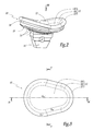
- the glenoid component 10 comprises a one-piece body 11 in the overall shape of a cup.
- the body 11 thus has two opposite main faces, namely a face 12 substantially hollow, intended to be turned towards the humeral head 4, and a generally convex or flat face 13, intended to be plated and secured against the bone of the glenoid G.
- the arrangements of the face 13 in order to fix the body 11 to the glenoid G are not limiting of the invention.
- grooves 14, adapted to come into direct contact with the osseous surface of the glenoid G are delimited in the face 13 and, on the other hand, the central region of this face 13 is provided, here in one-piece fashion, with a protruding keel 15 dimensioned to anchor deep in the glenoid G.
- this keel 15 is traversed by a hole inside which cement can be injected, in order to lock and stabilize the face 13 with respect to the glenoid.
- the immobilization of the keel can also be reinforced by a transverse screw.
- the arrangements of the face 13 may comprise or consist of several projecting studs in the bone material of the glenoid, in one or more through holes in which screws are received or, more generally, bone anchors with the glenoid, and / or a hydroxyapatite-based coating to facilitate osseointegration, etc.
- the body 11 includes, at one and the same time, a main part 16 which, on the side of the face 13, carries the grooves 14 and the wing 15, a peripheral edge 17, which extends all around the main part 16, and a zone 18 connecting to each other the main part 16 and the peripheral edge 17.
- the peripheral edge 17 has, on the face 12 of the support body 11, a convex surface S 17 which, in cross section as on the Figures 4 and 5 , has a curved profile.
- this curved profile substantially corresponds to an arc of a circle.
- the main part 16 and the connecting zone 18 have, on their side, on the face 12 of the body 11, concave surfaces, respectively referenced S 16 and S 18 .
- the concave surface S 16 is dimensioned to cooperate in an articular manner, that is to say in rotation and sliding, with the convex surface S 4 of the humeral head 4.
- the respective geometries of these surfaces S 4 and S 16 are designed to reproduce as closely as possible the anatomical articular behaviors of the shoulder.
- the curvature of the surface S 18 is greater than that of the surface S 16 , as can be seen in section on the Figures 4 and 5 .
- the respective peripheral contours of the main portion 16, the connecting zone 18 and the peripheral edge 17 have a shape reproducing that of the peripheral contour of the glenoid.
- this shape is oval, or even advantageously similar to a pear profile, that is to say to an elongated profile with rounded opposite ends, with one of these ends having a greater radius of curvature than the other extremity. This particular form faithfully reproduces the corresponding anatomy of the human glenus.
- the connecting zone 18 is provided with a peripheral groove 19 delimited in the face 13 of the body 11.
- This groove 19 thus forms a hollow in the material constituting the connection zone 18, reducing the thickness of the latter relative to on the one hand to the thickness of the main part 16 and, on the other hand, to the thickness of the peripheral edge 17.
- the groove 19 extends continuously over the entire periphery of the body 11, without interruption. In variant not shown, this groove 19 could be interrupted in one or more portions along the periphery of the body 11.
- the groove 19 has, in cross-section, a section with a V profile.
- This profile shape is not limiting of the invention, in the sense that other shapes are conceivable, such as a U-shaped profile, a W profile, a "accordion bellows" profile, etc.
- the groove 19 is designed and dimensioned to mechanically weaken the connection zone 18 in order to allow its elastic deformation with respect to both the main part 16 and the peripheral edge 17. In practice, this deformation is made by bringing the edges of the groove 19 closer or more closely together.
- the humeral head 4 rests against the body 11, at the level of its face 12. that the humeral head 4 cooperates with the central region of the main part 16, the surfaces S 4 and S 16 cooperate in an articulated manner, as explained above.
- the humeral head 4 deviates from the aforementioned central region and thus approaches a peripheral portion of the connecting zone 18 and the peripheral edge 17.
- the convex surface S 4 of the humeral head 'bears on the surface S 18 of the connection zone 18 the more curved concavity of the latter, relative to the S 16 area tends to return the humeral head to the central region of the main portion 16.
- the humeral head 4 bears against the peripheral edge 17, the convex surface S 17 of the latter simulates the presence of an anatomical marginal glenoid bead, which thus tends to retain the humeral head by abutment.
- the support of the humeral head against the peripheral edge 17 generates a tilting torque of this edge with respect to the main part 16, this couple tending to bring the edges of the groove 19 closer to one another, as indicated by the arrow F 10 on the figure 6 .
- the connecting zone 18 deforms, so that, as soon as the support of the humeral head 4 is released, the deformation energy accumulated in this zone 18 is released in an elastic manner: the edges of the throat 19 to go back to their original configuration. in such a way that the peripheral edge 17 pushes the humeral head 4 towards the central region of the main part 16.
- the presence of the groove 19 gives the peripheral edge 17 an elastic retaining capacity of the humeral head 4 whereas this peripheral edge 17 is advantageously made of the same hard material as the material constituting the main part 16.
- this main part 16 is hard, that is to say made of a material that will neither deform in its mass, nor to wear under the action of the constraints commonly observed within a shoulder joint.
- the material used to make the main part 16 and, more generally, to make the whole body 11, including the peripheral edge 17 and the connecting zone 18, is selected from high-density polyethylene, a metal alloy, pyrocarbon , polyetheretherketone (PEEK), etc.
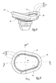
- the surgeon has the glenoid component 10 in different sizes.
- the surgeon has this glenoid component 2 in three different sizes, as shown on the figure 7 on which, in addition to the glenoid component 10 considered in the preceding figures, which is shown in solid lines, two other components 10, respectively smaller and larger than the component 10 of the previous figures, are shown in dashed lines.
- the three glenoid components considered on the figure 7 11 have homothetic bodies, except for the arrangements of their face 13, making it possible to fix them to the glenoid G.
- the three glenoid components 10 have different respective values for their dimension along any direction passing through two portions of their groove 19, diametrically opposed with respect to the central region of their main portion 16.
- the choice of the glenoid component 10 among the set of three available components induces a specific relative positioning for the groove 19: as shown schematically on the figure 7 , the implantation of the smallest of the three available components 10 leads to position the groove 19 inside the bone surface S G of the glenoid G, while the implantation of the largest of the three components 10 leads to position the groove 19 outside this bone surface S G.
- the implantation of the last of the three available components leads to position the groove 19 substantially in line with the peripheral periphery of the bone surface S G.
- the mechanical behavior of the connecting zone 18 is influenced by this relative positioning of the groove 19 and the bone surface S G of the glenoid G: according to whether the groove is outside, inside or on perpendicular to the peripheral periphery of this bone surface S G , the edges of the groove 19 move away from each other with more or less ease, that is to say under the action of a greater effort. or less important applied on the peripheral edge 17 by the humeral head 4.
- the surgeon can choose the size of the glenoid component 10 that he considers to be the most suitable.
- the component 20 comprises a body 21 support for the head humeral 4, this body 21 including, at the same time, a main part 26 of articulation with the head 4, a peripheral edge 27 of simulation of an anatomical marginal glenoid bead, and a zone 28 of connection between this main part and this peripheral edge.
- the main portion 26, the peripheral edge 27 and the connecting zone 28 have concave surfaces S 26 , convex S 27 and concave S 28 , geometrically and functionally similar to the surfaces S 16 , S 17 and S 18 of the component 10.
- the opposite face 23 of the body 21 is, like the face 13 of the body 11, adapted to be pressed against and secured to the bone of the glenoid G.
- the component 20 differs from the component 10 by the arrangement of its connecting zone 28, aimed at weakening the latter mechanically. Indeed, the groove 19 of the component 10 is replaced by a groove 29 delimited in the face 22 of the body 21.
- this groove 29 allows, in the same way as the groove 19, the elastic deformation of the connection zone 28 when the humeral head 4 is based on on the peripheral edge 27, by spacing and relative approximation of the edges facing this groove 29. More precisely, as indicated by the arrow F 20 on the figure 12 , the bearing action of the humeral head 4 tends to spread the edges of the groove 29, then, by elastic return of the material constituting the connecting zone 28, the aforementioned edges tend to get closer to each other .
Landscapes
- Health & Medical Sciences (AREA)
- Orthopedic Medicine & Surgery (AREA)
- Cardiology (AREA)
- Oral & Maxillofacial Surgery (AREA)
- Transplantation (AREA)
- Engineering & Computer Science (AREA)
- Biomedical Technology (AREA)
- Heart & Thoracic Surgery (AREA)
- Vascular Medicine (AREA)
- Life Sciences & Earth Sciences (AREA)
- Animal Behavior & Ethology (AREA)
- General Health & Medical Sciences (AREA)
- Public Health (AREA)
- Veterinary Medicine (AREA)
- Prostheses (AREA)
Abstract
Description
- La présente invention concerne un composant prothétique glénoïdien, ainsi qu'un jeu de tels composants.
- L'invention s'intéresse plus particulièrement à la restauration articulaire anatomique de la glène de l'omoplate d'un être humain, par un composant prothétique définissant une surface concave sur laquelle vient d'appuyer et s'articuler une tête humérale convexe soit prothétique, soit osseuse.
- Un grand nombre des composants prothétiques glénoïdiens actuels donnent satisfaction en ce qui concerne leur comportement cinématique pour l'articulation de l'épaule des patients. Toutefois, on constate que, en service, ces composants glénoïdiens induisent très fréquemment des surtensions sur l'environnement musculo-ligamentaire de l'épaule, sont rapidement sujets à des usures et des descellements, et/ou rendent instable l'articulation de l'épaule. Plus généralement, on peut dire que les performances cinématiques des composants glénoïdiens connus sont atteintes lorsque la tête humérale glisse, tourne et reste stable sur le composant glénoïdien. Par ailleurs, ces performances sont amoindries lorsqu'un des paramètres cinématiques au moins (rotation, glissement, stabilité) est dégradé.
- A l'inverse,
EP-A-1 776 935 a proposé de revêtir un corps prothétique suffisamment rigide pour être solidarisé fermement à l'os de la glène, par un corps souple d'appui pour la tête humérale. Ce corps d'appui souple est réalisé en un matériau élastique, tel que du polyuréthane élastomérique, qui forme, tout autour de sa partie centrale contre laquelle s'articule la tête humérale, un bord périphérique déformable dans son épaisseur, pour simuler un bourrelet marginal anatomique, parfois désigné sous son terme latin « labrum ». L'effet de ce bord déformable présente un réel intérêt dans le sens où il induit une coopération, avec la tête humérale, plus proche d'un comportement anatomique naturel. Toutefois, le matériau élastique précité, utilisé pour réaliser le corps d'appui souple, ne permet pas, en service, de garantir ni des performances cinématiques satisfaisantes pour l'articulation de l'épaule, ni une résistance suffisante à l'usure. - Le but de la présente invention est de proposer un composant glénoïdien qui, lorsqu'il coopère avec une tête humérale, concilie de bonnes performances cinématiques et un comportement le plus naturel possible.
- A cet effet, l'invention a pour objet un composant prothétique glénoïdien, tel que défini à la revendication 1.
- L'idée à la base de l'invention est de chercher à simuler un bourrelet marginal glénoïdien anatomique par le bord périphérique du corps d'appui, tout en réalisant ce bord périphérique avec un matériau aussi rigide, voire le même matériau, que celui utilisé pour réaliser la partie principale de ce corps d'appui. Bien entendu, la partie principale et le bord périphérique sont alors avantageusement réalisés d'un seul tenant, en étant venus de matière l'un avec l'autre. Pour ce faire, l'invention prévoit d'affaiblir mécaniquement la zone de liaison entre la partie principale et le bord périphérique, de manière à rendre cette zone de liaison élastiquement déformable par rapport au reste du corps d'appui. L'affaiblissement mécanique est conçu pour que, sous l'action de la tête humérale sur le bord périphérique, la zone de liaison précitée se déforme, en conférant alors au bord périphérique un comportement similaire, voire identique à celui d'un bourrelet marginal anatomique glénoïdien : ce bord périphérique permet ainsi de freiner, retenir et recentrer la tête humérale lorsque, en service, elle s'écarte de la région centrale de la partie principale du corps d'appui jusqu'à s'appuyer contre le bord périphérique. Dans le même temps, cette partie centrale peut présenter une géométrie et une dureté qui garantissent des performances cinématiques élevées et pérennes pour l'articulation entre le corps d'appui et la tête humérale.
- D'autres caractéristiques avantageuses du composant prothétique glénoïdien conforme à l'invention, prises isolément ou selon toutes les combinaisons techniquement possibles, sont spécifiées aux revendications dépendantes 2 à 9.
- L'invention a également pour objet un jeu d'au moins deux composants prothétiques glénoïdiens, tel que défini à la revendication 10.
- Grâce au jeu conforme à l'invention, un chirurgien dispose de plusieurs composants glénoïdiens contre lesquels une même tête humérale pourra s'articuler de manière sensiblement identique. En revanche, selon le composant glénoïdien choisi par le chirurgien parmi ceux à sa disposition, l'effet du bord périphérique du corps d'appui de ce composant, sur la tête humérale, sera légèrement différent : en effet, l'amplitude de la déformation élastique de la zone de liaison entre le bord périphérique et la partie principale de ce corps d'appui sera influencée par son positionnement relatif vis-à-vis de l'os de la glène dans lequel le composant sera implanté, en particulier selon que cette zone de liaison se retrouve située essentiellement à l'aplomb du pourtour périphérique de la glène ou bien à l'extérieur ou à l'intérieur de ce pourtour périphérique.
- L'invention sera mieux comprise à la lecture de la description qui va suivre, donnée uniquement à titre d'exemple et faite en se référant aux dessins sur lesquels :
- la
figure 1 est une représentation schématique de principe d'une prothèse d'épaule implantée sur un patient, comprenant un composant glénoïdien conforme à l'invention ; - la
figure 2 est une vue en perspective montrant seul le composant glénoïdien de lafigure 1 ; - la
figure 3 est une vue en élévation selon la flèche III de lafigure 2 ; - les
figures 4 et 5 sont des coupes selon respectivement les lignes IV-IV et V-V de lafigure 3 ; - la
figure 6 est une vue à plus grande échelle du détail cerclé VI sur lafigure 4 ; - la
figure 7 est une vue analogue à lafigure 5 , montrant, de manière schématique, le composant glénoïdien desfigures 1 à 6 ainsi que deux autres composants glénoïdiens, ces trois composants appartenant à un jeu conforme à l'invention ; et - les
figures 8 à 12 illustrent un autre mode de réalisation d'un composant glénoïdien conforme à l'invention, ces figures étant respectivement analogues auxfigures 2 à 6 . - Sur la
figure 1 est représentée une prothèse d'épaule totale 1 comprenant un composant 10 fixé à la glène G de l'omoplate d'un patient. Ce composant glénoïdien 10 est adapté pour coopérer par contact articulé avec un composant 2 de la prothèse 1, fixé à l'humérus H associé à l'épaule du patient. Dans l'exemple de réalisation considéré sur la figure, ce composant huméral 2 comporte une tige 3, à même d'être ancrée fixement dans le canal médullaire de l'humérus H, et une tête 4, portée fixement par la tige et délimitant extérieurement une surface convexe S4, ici de forme globalement hémisphérique. - Lorsque la prothèse 1 est en service, la surface convexe S4 de la tête humérale 4 s'appuie et s'articule contre le composant glénoïdien 10, comme expliqué en détail ci-après. A titre de variante non représentée, plutôt que le composant glénoïdien 10 coopère en service avec une tête humérale prothétique telle que la tête 4, la tête osseuse de l'humérus H peut être appuyée de manière articulée contre ce composant 10 : dans ce cas, la prothèse d'épaule n'inclut plus de composant huméral et est généralement qualifiée de prothèse partielle.
- Comme montré plus en détail sur les
figures 2 à 6 , le composant glénoïdien 10 comporte un corps monobloc 11 en forme globale de coupelle. Le corps 11 présente ainsi deux faces principales opposées, à savoir une face 12 essentiellement en creux, destinée à être tournée vers la tête humérale 4, et une face 13 globalement bombée ou plate, destinée à être plaquée et solidarisée contre l'os de la glène G. - En pratique, les aménagements de la face 13 afin de fixer le corps 11 à la glène G ne sont pas limitatifs de l'invention. Ainsi, dans l'exemple de réalisation considéré sur les figures, d'une part, des sillons 14, adaptés pour venir en prise directe avec la surface osseuse de la glène G, sont délimités dans la face 13 et, d'autre part, la région centrale de cette face 13 est munie, ici de façon monobloc, d'une quille saillante 15 dimensionnée pour venir s'ancrer profondément dans la glène G. Avantageusement, cette quille 15 est traversée par un trou à l'intérieur duquel du ciment peut être injecté, afin de verrouiller et de stabiliser la face 13 par rapport à la glène. L'immobilisation de la quille peut par ailleurs être renforcée par une vis transversale. A titre de variantes non représentées, les aménagements de la face 13 peuvent comprendre ou consister en plusieurs plots saillants d'emmanchement dans la matière osseuse de la glène, en un ou plusieurs trous traversants dans lesquels sont reçus des vis ou, plus généralement, des organes d'ancrage osseux avec la glène, et/ou en un revêtement à base d'hydroxyapatite pour faciliter l'ostéo-intégration, etc.
- Comme bien visible sur les
figures 3 à 5 , le corps 11 inclut, à la fois, une partie principale 16, qui, du côté de la face 13, porte les sillons 14 et l'aile 15, un bord périphérique 17, qui s'étend tout autour de la partie principale 16, et une zone 18 reliant l'un à l'autre la partie principale 16 et le bord périphérique 17. - Le bord périphérique 17 présente, sur la face 12 du corps d'appui 11, une surface convexe S17 qui, en coupe transversale comme sur les
figures 4 et 5 , présente un profil incurvé. Dans l'exemple de réalisation considéré sur les figures, ce profil incurvé correspond sensiblement à un arc de cercle. - La partie principale 16 et la zone de liaison 18 présentent, quant à elles, sur la face 12 du corps 11, des surfaces concaves, respectivement référencées S16 et S18. La surface concave S16 est dimensionnée pour coopérer de façon articulaire, c'est-à-dire en rotation et glissement, avec la surface convexe S4 de la tête humérale 4. De façon connue en soi, les géométries respectives de ces surfaces S4 et S16 sont conçues pour reproduire aussi fidèlement que possible les comportements articulaires anatomiques de l'épaule.
- Avantageusement, pour des raisons qui apparaitront plus loin, la courbure de la surface S18 est plus grande que celle de la surface S16, comme bien visible en coupe sur les
figures 4 et 5 . - Avantageusement, en observant le corps 11 suivant une direction normale à sa face 12, comme sur la
figure 3 , les contours périphériques respectifs de la partie principale 16, de la zone de liaison 18 et du bord périphérique 17 ont une forme reproduisant celle du contour périphérique de la glène. En pratique, cette forme est ovale, voire avantageusement s'apparente à un profil en poire, c'est-à-dire à un profil allongé aux extrémités opposées arrondies, avec l'une de ces extrémités présentant un rayon de courbure plus important que l'autre extrémité. Cette forme particulière reproduit fidèlement l'anatomie correspondante de la glène humaine. - Comme bien visible sur la
figure 6 , la zone de liaison 18 est munie d'une gorge périphérique 19, délimitée dans la face 13 du corps 11. Cette gorge 19 forme ainsi un creux dans la matière constituant la zone de liaison 18, réduisant l'épaisseur de cette dernière par rapport, d'une part, à l'épaisseur de la partie principale 16 et, d'autre part, à l'épaisseur du bord périphérique 17. - Dans l'exemple de réalisation considéré sur les figures, la gorge 19 s'étend de manière continue sur toute la périphérie du corps 11, sans interruption. En variante non représentée, cette gorge 19 pourrait être interrompue en une ou plusieurs portions suivant la périphérie du corps 11.
- De même, dans le mode de réalisation considéré sur les figures, la gorge 19 présente, en coupe transversale, une section à profil en V. Cette forme de profil n'est pas limitative de l'invention, dans le sens où d'autres formes sont envisageables, telles qu'un profil en U, un profil en W, un profil en « soufflet d'accordéon », etc.
- Dans tous les cas, la gorge 19 est conçue et dimensionnée pour affaiblir mécaniquement la zone de liaison 18 afin d'autoriser sa déformation élastique par rapport, à la fois, à la partie principale 16 et au bord périphérique 17. En pratique, cette déformation est réalisée par rapprochement ou écartement des bords en regard de la gorge 19.
- En service, c'est-à-dire lorsque la prothèse 1 est implantée et que le patient ainsi prothésé sollicite l'articulation de son épaule, la tête humérale 4 s'appuie contre le corps 11, au niveau de sa face 12. Tant que la tête humérale 4 coopère avec la région centrale de la partie principale 16, les surfaces S4 et S16 coopèrent de manière articulée, comme expliqué plus haut.
- Dans certaines configurations de sollicitation, la tête humérale 4 s'écarte de la région centrale précitée et se rapproche ainsi d'une portion périphérique de la zone de liaison 18 et du bord périphérique 17. Lorsque la surface convexe S4 de la tête humérale s'appuie sur la surface S18 de la zone de liaison 18, la concavité plus courbée de cette dernière, par rapport à la surface S16, tend à ramener la tête humérale vers la région centrale de la partie principale 16. De plus, lorsque, le cas échéant, la tête humérale 4 s'appuie contre le bord périphérique 17, la surface convexe S17 de ce dernier simule la présence d'un bourrelet marginal glénoïdien anatomique, qui tend ainsi à retenir par butée la tête humérale. De surcroît, l'appui de la tête humérale contre le bord périphérique 17 génère un couple de basculement de ce bord par rapport à la partie principale 16, ce couple tendant à rapprocher l'un de l'autre les bords de la gorge 19, comme indiqué par la flèche F10 sur la
figure 6 . Il en résulte que la zone de liaison 18 se déforme, si bien que, dès que l'appui de la tête humérale 4 se relâche, l'énergie de déformation accumulée dans cette zone 18 se libère de manière élastique : les bords de la gorge 19 s'écartent, pour reprendre leur configuration initiale de manière que le bord périphérique 17 repousse la tête humérale 4 vers la région centrale de la partie principale 16. - Ainsi, on comprend que la présence de la gorge 19 confère au bord périphérique 17 une capacité de retenue élastique de la tête humérale 4 alors que ce bord périphérique 17 est avantageusement réalisé avec le même matériau dur que le matériau constituant la partie principale 16. En effet, pour garantir la précision et la pérennité de la coopération mécanique articulaire entre la partie principale 16 et la tête humérale 4, cette partie principale 16 est dure, c'est-à-dire réalisée en un matériau qui ne va ni se déformer dans sa masse, ni s'user sous l'action des contraintes couramment constatées au sein d'une articulation d'épaule. Typiquement, le matériau utilisé pour réaliser la partie principale 16 et, plus généralement, pour réaliser tout le corps 11, y compris le bord périphérique 17 et la zone de liaison 18, est choisi parmi du polyéthylène haute densité, un alliage métallique, du pyrocarbone, du polyétheréthercétone (PEEK), etc.
- Avantageusement, lors du traitement chirurgical de l'épaule du patient, le chirurgien dispose du composant glénoïdien 10 en différentes tailles. Par exemple, le chirurgien dispose de ce composant glénoïdien 2 en trois tailles différentes, comme montré sur la
figure 7 sur laquelle, en plus du composant glénoïdien 10 considéré sur les figures précédentes, qui est représenté en traits pleins, deux autres composants 10, respectivement plus petit et plus grand que le composant 10 des figures précédentes, sont représentés en pointillés. Plus précisément, les trois composants glénoïdiens 10 considérés sur lafigure 7 présentent des corps 11 homothétiques, excepté pour ce qui concerne les aménagements de leur face 13, permettant de les fixer à la glène G. Ainsi, les trois composants glénoïdiens 10 présentent des valeurs respectives différentes pour leur dimension suivant n'importe quelle direction passant par deux portions de leur gorge 19, diamétralement opposées par rapport à la région centrale de leur partie principale 16. - Il en résulte que, vis-à-vis de la glène G du patient opéré, le choix du composant glénoïdien 10 parmi le jeu des trois composants disponibles induit un positionnement relatif spécifique pour la gorge 19 : comme montré de manière schématique sur la
figure 7 , l'implantation du plus petit des trois composants disponibles 10 conduit à positionner la gorge 19 à l'intérieur de la surface osseuse SG de la glène G, tandis que l'implantation du plus grand des trois composants 10 conduit à positionner la gorge 19 à l'extérieur de cette surface osseuse SG. De façon intermédiaire, l'implantation du dernier des trois composants disponibles conduit à positionner la gorge 19 sensiblement à l'aplomb du pourtour périphérique de la surface osseuse SG. - Le comportement mécanique de la zone de liaison 18 est influencé par ce positionnement relatif de la gorge 19 et de la surface osseuse SG de la glène G : selon que la gorge se trouve à l'extérieur, à l'intérieur ou à l'aplomb du pourtour périphérique de cette surface osseuse SG, les bords de la gorge 19 s'écartent l'un de l'autre avec plus ou moins de facilité, c'est-à-dire sous l'action d'un effort plus ou moins important appliqué sur le bord périphérique 17 par la tête humérale 4.
- Ainsi, notamment selon les cas pathologiques de reconstruction de l'articulation de l'épaule, le chirurgien peut choisir la taille du composant glénoïdien 10 qu'il considère comme étant la mieux adaptée.
- Sur les
figures 8 à 12 est représenté un second mode de réalisation d'un composant glénoïdien 20 dont les constituants identiques à ceux du composant glénoïdien 10 sont repérés par les mêmes références numériques, augmentées de 10. Ainsi, le composant 20 comprend un corps 21 d'appui pour la tête humérale 4, ce corps 21 incluant, à la fois, une partie principale 26 d'articulation avec la tête 4, un bord périphérique 27 de simulation d'un bourrelet marginal glénoïdien anatomique, et une zone 28 de liaison entre cette partie principale et ce bord périphérique. Sur la face 22 du corps 21, tournée vers la tête humérale 4 en service, la partie principale 26, le bord périphérique 27 et la zone de liaison 28 présentent des surfaces respectivement concave S26, convexe S27 et concave S28, géométriquement et fonctionnellement analogues aux surfaces S16, S17 et S18 du composant 10. La face opposée 23 du corps 21 est, comme la face 13 du corps 11, adaptée pour être plaquée contre et solidarisée à l'os de la glène G. - Comme bien visible sur les
figures 10 à 12 , le composant 20 se distingue du composant 10 par l'aménagement de sa zone de liaison 28, visant à affaiblir mécaniquement cette dernière. En effet, la gorge 19 du composant 10 est remplacée par un sillon 29 délimité dans la face 22 du corps 21. - En service, ce sillon 29 permet, de la même façon que la gorge 19, la déformation élastique de la zone de liaison 28 lorsque la tête humérale 4 s'appuie sur le bord périphérique 27, par écartement et rapprochement relatif des bords en regard de ce sillon 29. Plus précisément, comme indiqué par la flèche F20 sur la
figure 12 , l'action d'appui de la tête humérale 4 tend à écarter les bords du sillon 29, puis, par rappel élastique de la matière constituant la zone de liaison 28, les bords précités tendent à se rapprocher l'un de l'autre. - Divers aménagements et variantes aux composants glénoïdiens 10 et 20 décrits jusqu'ici sont par ailleurs envisageables. A titre d'exemples :
- la zone de liaison 18 peut inclure plusieurs gorges 19, disposées l'une après l'autre suivant une direction reliant la partie principale 16 et le bord périphérique 17 ; de même, la zone de liaison 28 peut présenter ainsi plusieurs sillons 29 ; et/ou
- les modes de réalisation des composants 10 et 20 peuvent être combinés, c'est-à-dire que la zone de liaison entre leur partie principale et leur bord périphérique peut être pourvue, à la fois, d'au moins une gorge 19 et d'au moins un sillon 29.
Claims (10)
- Composant prothétique glénoïdien (10 ; 20),
comportant un corps (11 ; 21) d'appui pour une tête humérale prothétique (4) ou osseuse, lequel corps d'appui inclut, d'une part, une partie principale (16 ; 26) d'articulation avec la tête humérale et, d'autre part, un bord périphérique (17 ; 27), caractérisé en ce que la zone (18 ; 28) de liaison entre la partie principale (16 ; 26) et le bord périphérique (17 ; 27) est mécaniquement affaiblie pour, en service, rendre cette zone de liaison élastiquement déformable par rapport au reste du corps d'appui (11 ; 21) sous l'action de la tête humérale (4). - Composant suivant la revendication 1, caractérisé en ce que ladite zone de liaison (18 ; 28) est mécaniquement affaiblie suivant toute la périphérie du corps d'appui (11 ; 21).
- Composant suivant la revendication 1, caractérisé en ce que ladite zone de liaison est mécaniquement affaiblie en une portion seulement ou en plusieurs portions distinctes suivant la périphérie du corps d'appui.
- Composant suivant l'une quelconque des revendications précédentes, caractérisé en ce que ladite zone de liaison (18) est mécaniquement affaiblie par au moins une gorge (19) délimitée dans la face (13) du corps d'appui (11), opposée à celle (12) contre laquelle la tête humérale (4) s'appuie en service.
- Composant suivant l'une quelconque des revendications précédentes, caractérisé en ce que ladite zone de liaison (28) est mécaniquement affaiblie par au moins un sillon (29) délimité dans la face (22) du corps d'appui (21), contre laquelle la tête humérale (4) s'appuie en service.
- Composant suivant l'une quelconque des revendications précédentes, caractérisé en ce que le bord périphérique (17 ; 27) et ladite zone de liaison (18 ; 28) présentent, sur la face (12 ; 22) du corps d'appui (11 ; 21) contre laquelle la tête humérale (4) s'appuie en service, des surfaces respectivement convexe (S17 ; S27) et concave (S18 S28).
- Composant suivant la revendication 6, caractérisé en ce que la partie principale (16 ; 26) présente, sur la face (12 ; 22) du corps d'appui (11 ; 21) contre laquelle la tête humérale (4) s'appuie en service, une surface concave (S16 ; S26) dont la courbure est moins grande que celle de la surface concave (S18 ; S28) de la zone de liaison (18 ; 28).
- Composant suivant l'une quelconque des revendications précédentes, caractérisé en ce que le corps d'appui (11 ; 21) présente, à l'opposé de sa face (12 ; 22) contre laquelle la tête humérale (4) s'appuie en service, une face (13 ; 23) adaptée pour être plaquée contre et solidarisée à l'os d'une glène (G).
- Composant suivant l'une quelconque des revendications précédentes, caractérisé en ce que le corps d'appui (11 ; 21) est monobloc.
- Jeu d'au moins deux composants prophétiques glénoïdiens (10 ; 20), caractérisé en ce que chaque composant glénoïdien (10 ; 20) est conforme à l'une quelconque des revendications précédentes, et en ce que, suivant au moins une même direction passant par deux portions de la zone de liaison (18 ; 28) des composants, diamétralement opposées par rapport à la région centrale de la partie principale (16 ; 26) des composants, les corps d'appui (11 ; 21) de ces composants présentent une dimension ayant des valeurs différentes entre eux.
Applications Claiming Priority (1)
| Application Number | Priority Date | Filing Date | Title |
|---|---|---|---|
| FR0954078A FR2946862B1 (fr) | 2009-06-17 | 2009-06-17 | Composant prothetique glenoidien et jeu d'au moins deux de ces composants. |
Publications (2)
| Publication Number | Publication Date |
|---|---|
| EP2263613A1 true EP2263613A1 (fr) | 2010-12-22 |
| EP2263613B1 EP2263613B1 (fr) | 2012-12-19 |
Family
ID=41629924
Family Applications (1)
| Application Number | Title | Priority Date | Filing Date |
|---|---|---|---|
| EP10166096A Not-in-force EP2263613B1 (fr) | 2009-06-17 | 2010-06-16 | Composant prothétique glénoïdien et jeu d'au moins deux de ces composants |
Country Status (3)
| Country | Link |
|---|---|
| US (1) | US20100324691A1 (fr) |
| EP (1) | EP2263613B1 (fr) |
| FR (1) | FR2946862B1 (fr) |
Cited By (1)
| Publication number | Priority date | Publication date | Assignee | Title |
|---|---|---|---|---|
| EP2446859A1 (fr) | 2010-10-28 | 2012-05-02 | Les Laboratoires Osteal Medical | Implant glénoïdien. |
Families Citing this family (10)
| Publication number | Priority date | Publication date | Assignee | Title |
|---|---|---|---|---|
| US7892288B2 (en) | 2001-08-27 | 2011-02-22 | Zimmer Technology, Inc. | Femoral augments for use with knee joint prosthesis |
| US20030065397A1 (en) | 2001-08-27 | 2003-04-03 | Hanssen Arlen D. | Prosthetic implant support structure |
| AU2011314157A1 (en) | 2010-09-29 | 2013-05-09 | Zimmer, Inc. | Pyrolytic carbon implants with porous fixation component and methods of making the same |
| US8986392B2 (en) * | 2011-08-25 | 2015-03-24 | S. Gary Brown | Femoral implant |
| US20150272741A1 (en) * | 2014-03-26 | 2015-10-01 | Biomet Manufacturing, Llc | Press-fit glenoid with peripheral compression pegs |
| US9681960B2 (en) | 2014-05-16 | 2017-06-20 | Howmedica Osteonics Corp. | Guides for fracture system |
| US10575968B2 (en) | 2014-05-16 | 2020-03-03 | Howmedica Osteonics Corp. | Guides for fracture system |
| US10342669B2 (en) * | 2015-04-07 | 2019-07-09 | Zimmer, Inc. | Convertible glenoid |
| EP3570787B1 (fr) | 2017-01-20 | 2022-05-04 | Biomet Manufacturing, LLC | Composant d'augmentation modulaire |
| CN109730760A (zh) * | 2019-01-24 | 2019-05-10 | 丁伟 | 一种肩关节骨性修复重建装置 |
Citations (4)
| Publication number | Priority date | Publication date | Assignee | Title |
|---|---|---|---|---|
| US5358525A (en) * | 1992-12-28 | 1994-10-25 | Fox John E | Bearing surface for prosthesis and replacement of meniscal cartilage |
| EP1776935A1 (fr) | 2005-10-24 | 2007-04-25 | Benoist Girard Sas | Composant de prosthese glenoide |
| WO2007109319A2 (fr) * | 2006-03-21 | 2007-09-27 | Axiom Orthopaedics, Inc. | Élément glénoïde à stabilité de fixation améliorée |
| EP1844737A2 (fr) * | 2006-04-13 | 2007-10-17 | Tornier | Composant glénoïdien pour prothèse totale d'épaule, jeu de tels composants, et prothèse totale d'épaule comprenant un tel composant |
Family Cites Families (10)
| Publication number | Priority date | Publication date | Assignee | Title |
|---|---|---|---|---|
| US4044403A (en) * | 1976-11-01 | 1977-08-30 | Howmedica, Inc. | Implantable joint prosthesis |
| AU2003228083A1 (en) * | 2002-05-23 | 2003-12-12 | Discure, Ltd. | Joint and dental implants |
| JP2006501977A (ja) * | 2002-10-07 | 2006-01-19 | コンフォーミス・インコーポレイテッド | 関節表面に適合する3次元外形を伴う最小限侵襲性関節インプラント |
| EP1965736A2 (fr) * | 2006-02-09 | 2008-09-10 | Zimmer GmbH | Prothèse |
| US20110166671A1 (en) * | 2006-11-07 | 2011-07-07 | Kellar Franz W | Prosthetic joint |
| US7905919B2 (en) * | 2006-11-07 | 2011-03-15 | Biomedflex Llc | Prosthetic joint |
| US8070823B2 (en) * | 2006-11-07 | 2011-12-06 | Biomedflex Llc | Prosthetic ball-and-socket joint |
| WO2008058205A1 (fr) * | 2006-11-07 | 2008-05-15 | Biomedflex, Llc | Implants médicaux |
| US8016884B2 (en) * | 2008-04-09 | 2011-09-13 | Active Implants Corporation | Tensioned meniscus prosthetic devices and associated methods |
| US9549820B2 (en) * | 2009-06-25 | 2017-01-24 | Zimmer, Inc. | Glenoid implant with synthetic labrum |
-
2009
- 2009-06-17 FR FR0954078A patent/FR2946862B1/fr not_active Expired - Fee Related
-
2010
- 2010-06-16 EP EP10166096A patent/EP2263613B1/fr not_active Not-in-force
- 2010-06-17 US US12/817,878 patent/US20100324691A1/en not_active Abandoned
Patent Citations (4)
| Publication number | Priority date | Publication date | Assignee | Title |
|---|---|---|---|---|
| US5358525A (en) * | 1992-12-28 | 1994-10-25 | Fox John E | Bearing surface for prosthesis and replacement of meniscal cartilage |
| EP1776935A1 (fr) | 2005-10-24 | 2007-04-25 | Benoist Girard Sas | Composant de prosthese glenoide |
| WO2007109319A2 (fr) * | 2006-03-21 | 2007-09-27 | Axiom Orthopaedics, Inc. | Élément glénoïde à stabilité de fixation améliorée |
| EP1844737A2 (fr) * | 2006-04-13 | 2007-10-17 | Tornier | Composant glénoïdien pour prothèse totale d'épaule, jeu de tels composants, et prothèse totale d'épaule comprenant un tel composant |
Cited By (2)
| Publication number | Priority date | Publication date | Assignee | Title |
|---|---|---|---|---|
| EP2446859A1 (fr) | 2010-10-28 | 2012-05-02 | Les Laboratoires Osteal Medical | Implant glénoïdien. |
| FR2966719A1 (fr) * | 2010-10-28 | 2012-05-04 | Osteal Medical Lab | Implant glenoidien. |
Also Published As
| Publication number | Publication date |
|---|---|
| EP2263613B1 (fr) | 2012-12-19 |
| FR2946862B1 (fr) | 2011-07-08 |
| FR2946862A1 (fr) | 2010-12-24 |
| US20100324691A1 (en) | 2010-12-23 |
Similar Documents
| Publication | Publication Date | Title |
|---|---|---|
| EP2263613B1 (fr) | Composant prothétique glénoïdien et jeu d'au moins deux de ces composants | |
| EP2385812B1 (fr) | Tige d'ancrage intra médullaire pour tête d'implant orthopédique | |
| EP2243444B1 (fr) | Dispositif de fixation à la glène d'un composant articulaire glénoïdien pour prothèse d'épaule, ainsi que prothèse d'épaule correspondante | |
| EP1510190B1 (fr) | Composant glénoidien de prothèse d'épaule et prothèse totale d'épaule incorporant un tel composant | |
| CA2466661C (fr) | Prothese d'articulation vertebrale posterieure | |
| WO1994004100A1 (fr) | Prothese discale intervertebrale | |
| FR3132204A1 (fr) | Prothese de cheville amelioree | |
| FR2932079A1 (fr) | Prothese totale de genou | |
| FR2601873A1 (fr) | Prothese totale intracondylienne du genou | |
| FR3021524A1 (fr) | Tige d'ancrage metacarpien, notamment pour une prothese trapezo-metacarpienne | |
| WO2006048520A1 (fr) | Prothese de tete radiale inferieure | |
| WO2009092907A2 (fr) | Prothese de disques intervertebraux | |
| FR3019032A1 (fr) | Implant femoral comportant une portion de reception avec des picots d’ancrage et prothese totale de genou comprenant un tel implant femoral | |
| FR2692776A1 (fr) | Prothèse totale pour articulations des os, notamment de la main et du pied. | |
| EP2468217B1 (fr) | Implant d'hémi-arthroplastie métatarsien | |
| CA2586800C (fr) | Prothese acetabulaire destinee a etre fixee sans ciment | |
| FR2728160A1 (fr) | Systeme de prothese de hanche a tiges cimentees et sans ciment utilisant une rape universelle | |
| EP3005989B1 (fr) | Implant de resurfaçage du radius distal | |
| EP2524671B1 (fr) | Implant articulaire d'interposition métatarso-phalangien ou métacarpo-phalangien | |
| EP1706076B1 (fr) | Prothese discale intervertebrale | |
| FR2882251A1 (fr) | Implant tibial et prothese de genou unicomportimentaire le comportant | |
| EP1173118A1 (fr) | Prothese totale de genou a charniere et rattrapage automatique d'usure | |
| FR2863481A1 (fr) | Prothese de genou antero-postero-stabilisee a plateau tibial pivotant | |
| FR3008607A1 (fr) | Kit chirurgical pour realiser une arthroplastie de l'epaule | |
| FR2909278A1 (fr) | Prothese d'articulation trapezo-metacarpienne. |
Legal Events
| Date | Code | Title | Description |
|---|---|---|---|
| PUAI | Public reference made under article 153(3) epc to a published international application that has entered the european phase |
Free format text: ORIGINAL CODE: 0009012 |
|
| AK | Designated contracting states |
Kind code of ref document: A1 Designated state(s): AL AT BE BG CH CY CZ DE DK EE ES FI FR GB GR HR HU IE IS IT LI LT LU LV MC MK MT NL NO PL PT RO SE SI SK SM TR |
|
| AX | Request for extension of the european patent |
Extension state: BA ME RS |
|
| 17P | Request for examination filed |
Effective date: 20110323 |
|
| GRAP | Despatch of communication of intention to grant a patent |
Free format text: ORIGINAL CODE: EPIDOSNIGR1 |
|
| RIC1 | Information provided on ipc code assigned before grant |
Ipc: A61F 2/40 20060101AFI20120628BHEP |
|
| GRAS | Grant fee paid |
Free format text: ORIGINAL CODE: EPIDOSNIGR3 |
|
| GRAA | (expected) grant |
Free format text: ORIGINAL CODE: 0009210 |
|
| AK | Designated contracting states |
Kind code of ref document: B1 Designated state(s): AL AT BE BG CH CY CZ DE DK EE ES FI FR GB GR HR HU IE IS IT LI LT LU LV MC MK MT NL NO PL PT RO SE SI SK SM TR |
|
| RAP1 | Party data changed (applicant data changed or rights of an application transferred) |
Owner name: TORNIER |
|
| REG | Reference to a national code |
Ref country code: GB Ref legal event code: FG4D Free format text: NOT ENGLISH |
|
| REG | Reference to a national code |
Ref country code: CH Ref legal event code: EP |
|
| REG | Reference to a national code |
Ref country code: AT Ref legal event code: REF Ref document number: 588962 Country of ref document: AT Kind code of ref document: T Effective date: 20130115 |
|
| REG | Reference to a national code |
Ref country code: DE Ref legal event code: R096 Ref document number: 602010004157 Country of ref document: DE Effective date: 20130207 |
|
| PG25 | Lapsed in a contracting state [announced via postgrant information from national office to epo] |
Ref country code: NO Free format text: LAPSE BECAUSE OF FAILURE TO SUBMIT A TRANSLATION OF THE DESCRIPTION OR TO PAY THE FEE WITHIN THE PRESCRIBED TIME-LIMIT Effective date: 20130319 Ref country code: FI Free format text: LAPSE BECAUSE OF FAILURE TO SUBMIT A TRANSLATION OF THE DESCRIPTION OR TO PAY THE FEE WITHIN THE PRESCRIBED TIME-LIMIT Effective date: 20121219 Ref country code: ES Free format text: LAPSE BECAUSE OF FAILURE TO SUBMIT A TRANSLATION OF THE DESCRIPTION OR TO PAY THE FEE WITHIN THE PRESCRIBED TIME-LIMIT Effective date: 20130330 Ref country code: SE Free format text: LAPSE BECAUSE OF FAILURE TO SUBMIT A TRANSLATION OF THE DESCRIPTION OR TO PAY THE FEE WITHIN THE PRESCRIBED TIME-LIMIT Effective date: 20121219 Ref country code: HR Free format text: LAPSE BECAUSE OF FAILURE TO SUBMIT A TRANSLATION OF THE DESCRIPTION OR TO PAY THE FEE WITHIN THE PRESCRIBED TIME-LIMIT Effective date: 20121219 Ref country code: LT Free format text: LAPSE BECAUSE OF FAILURE TO SUBMIT A TRANSLATION OF THE DESCRIPTION OR TO PAY THE FEE WITHIN THE PRESCRIBED TIME-LIMIT Effective date: 20121219 |
|
| REG | Reference to a national code |
Ref country code: NL Ref legal event code: VDEP Effective date: 20121219 Ref country code: AT Ref legal event code: MK05 Ref document number: 588962 Country of ref document: AT Kind code of ref document: T Effective date: 20121219 |
|
| REG | Reference to a national code |
Ref country code: LT Ref legal event code: MG4D |
|
| PG25 | Lapsed in a contracting state [announced via postgrant information from national office to epo] |
Ref country code: SI Free format text: LAPSE BECAUSE OF FAILURE TO SUBMIT A TRANSLATION OF THE DESCRIPTION OR TO PAY THE FEE WITHIN THE PRESCRIBED TIME-LIMIT Effective date: 20121219 Ref country code: LV Free format text: LAPSE BECAUSE OF FAILURE TO SUBMIT A TRANSLATION OF THE DESCRIPTION OR TO PAY THE FEE WITHIN THE PRESCRIBED TIME-LIMIT Effective date: 20121219 Ref country code: GR Free format text: LAPSE BECAUSE OF FAILURE TO SUBMIT A TRANSLATION OF THE DESCRIPTION OR TO PAY THE FEE WITHIN THE PRESCRIBED TIME-LIMIT Effective date: 20130320 |
|
| REG | Reference to a national code |
Ref country code: FR Ref legal event code: GC Effective date: 20130515 |
|
| PG25 | Lapsed in a contracting state [announced via postgrant information from national office to epo] |
Ref country code: EE Free format text: LAPSE BECAUSE OF FAILURE TO SUBMIT A TRANSLATION OF THE DESCRIPTION OR TO PAY THE FEE WITHIN THE PRESCRIBED TIME-LIMIT Effective date: 20121219 Ref country code: SK Free format text: LAPSE BECAUSE OF FAILURE TO SUBMIT A TRANSLATION OF THE DESCRIPTION OR TO PAY THE FEE WITHIN THE PRESCRIBED TIME-LIMIT Effective date: 20121219 Ref country code: BG Free format text: LAPSE BECAUSE OF FAILURE TO SUBMIT A TRANSLATION OF THE DESCRIPTION OR TO PAY THE FEE WITHIN THE PRESCRIBED TIME-LIMIT Effective date: 20130319 Ref country code: CZ Free format text: LAPSE BECAUSE OF FAILURE TO SUBMIT A TRANSLATION OF THE DESCRIPTION OR TO PAY THE FEE WITHIN THE PRESCRIBED TIME-LIMIT Effective date: 20121219 Ref country code: IS Free format text: LAPSE BECAUSE OF FAILURE TO SUBMIT A TRANSLATION OF THE DESCRIPTION OR TO PAY THE FEE WITHIN THE PRESCRIBED TIME-LIMIT Effective date: 20130419 Ref country code: AT Free format text: LAPSE BECAUSE OF FAILURE TO SUBMIT A TRANSLATION OF THE DESCRIPTION OR TO PAY THE FEE WITHIN THE PRESCRIBED TIME-LIMIT Effective date: 20121219 |
|
| PG25 | Lapsed in a contracting state [announced via postgrant information from national office to epo] |
Ref country code: PT Free format text: LAPSE BECAUSE OF FAILURE TO SUBMIT A TRANSLATION OF THE DESCRIPTION OR TO PAY THE FEE WITHIN THE PRESCRIBED TIME-LIMIT Effective date: 20130419 Ref country code: RO Free format text: LAPSE BECAUSE OF FAILURE TO SUBMIT A TRANSLATION OF THE DESCRIPTION OR TO PAY THE FEE WITHIN THE PRESCRIBED TIME-LIMIT Effective date: 20121219 Ref country code: PL Free format text: LAPSE BECAUSE OF FAILURE TO SUBMIT A TRANSLATION OF THE DESCRIPTION OR TO PAY THE FEE WITHIN THE PRESCRIBED TIME-LIMIT Effective date: 20121219 Ref country code: NL Free format text: LAPSE BECAUSE OF FAILURE TO SUBMIT A TRANSLATION OF THE DESCRIPTION OR TO PAY THE FEE WITHIN THE PRESCRIBED TIME-LIMIT Effective date: 20121219 |
|
| PLBE | No opposition filed within time limit |
Free format text: ORIGINAL CODE: 0009261 |
|
| STAA | Information on the status of an ep patent application or granted ep patent |
Free format text: STATUS: NO OPPOSITION FILED WITHIN TIME LIMIT |
|
| PG25 | Lapsed in a contracting state [announced via postgrant information from national office to epo] |
Ref country code: DK Free format text: LAPSE BECAUSE OF FAILURE TO SUBMIT A TRANSLATION OF THE DESCRIPTION OR TO PAY THE FEE WITHIN THE PRESCRIBED TIME-LIMIT Effective date: 20121219 |
|
| 26N | No opposition filed |
Effective date: 20130920 |
|
| PG25 | Lapsed in a contracting state [announced via postgrant information from national office to epo] |
Ref country code: CY Free format text: LAPSE BECAUSE OF FAILURE TO SUBMIT A TRANSLATION OF THE DESCRIPTION OR TO PAY THE FEE WITHIN THE PRESCRIBED TIME-LIMIT Effective date: 20121219 |
|
| BERE | Be: lapsed |
Owner name: TORNIER Effective date: 20130630 |
|
| REG | Reference to a national code |
Ref country code: DE Ref legal event code: R097 Ref document number: 602010004157 Country of ref document: DE Effective date: 20130920 |
|
| PG25 | Lapsed in a contracting state [announced via postgrant information from national office to epo] |
Ref country code: MC Free format text: LAPSE BECAUSE OF FAILURE TO SUBMIT A TRANSLATION OF THE DESCRIPTION OR TO PAY THE FEE WITHIN THE PRESCRIBED TIME-LIMIT Effective date: 20121219 |
|
| PG25 | Lapsed in a contracting state [announced via postgrant information from national office to epo] |
Ref country code: BE Free format text: LAPSE BECAUSE OF NON-PAYMENT OF DUE FEES Effective date: 20130630 |
|
| REG | Reference to a national code |
Ref country code: CH Ref legal event code: PL |
|
| PG25 | Lapsed in a contracting state [announced via postgrant information from national office to epo] |
Ref country code: MT Free format text: LAPSE BECAUSE OF FAILURE TO SUBMIT A TRANSLATION OF THE DESCRIPTION OR TO PAY THE FEE WITHIN THE PRESCRIBED TIME-LIMIT Effective date: 20121219 |
|
| PG25 | Lapsed in a contracting state [announced via postgrant information from national office to epo] |
Ref country code: CH Free format text: LAPSE BECAUSE OF NON-PAYMENT OF DUE FEES Effective date: 20140630 Ref country code: LI Free format text: LAPSE BECAUSE OF NON-PAYMENT OF DUE FEES Effective date: 20140630 |
|
| PG25 | Lapsed in a contracting state [announced via postgrant information from national office to epo] |
Ref country code: SM Free format text: LAPSE BECAUSE OF FAILURE TO SUBMIT A TRANSLATION OF THE DESCRIPTION OR TO PAY THE FEE WITHIN THE PRESCRIBED TIME-LIMIT Effective date: 20121219 |
|
| REG | Reference to a national code |
Ref country code: FR Ref legal event code: PLFP Year of fee payment: 6 |
|
| PG25 | Lapsed in a contracting state [announced via postgrant information from national office to epo] |
Ref country code: TR Free format text: LAPSE BECAUSE OF FAILURE TO SUBMIT A TRANSLATION OF THE DESCRIPTION OR TO PAY THE FEE WITHIN THE PRESCRIBED TIME-LIMIT Effective date: 20121219 |
|
| PG25 | Lapsed in a contracting state [announced via postgrant information from national office to epo] |
Ref country code: LU Free format text: LAPSE BECAUSE OF NON-PAYMENT OF DUE FEES Effective date: 20130616 Ref country code: MK Free format text: LAPSE BECAUSE OF FAILURE TO SUBMIT A TRANSLATION OF THE DESCRIPTION OR TO PAY THE FEE WITHIN THE PRESCRIBED TIME-LIMIT Effective date: 20121219 Ref country code: HU Free format text: LAPSE BECAUSE OF FAILURE TO SUBMIT A TRANSLATION OF THE DESCRIPTION OR TO PAY THE FEE WITHIN THE PRESCRIBED TIME-LIMIT; INVALID AB INITIO Effective date: 20100616 |
|
| PGFP | Annual fee paid to national office [announced via postgrant information from national office to epo] |
Ref country code: IE Payment date: 20150519 Year of fee payment: 6 |
|
| REG | Reference to a national code |
Ref country code: FR Ref legal event code: RG Effective date: 20160128 |
|
| REG | Reference to a national code |
Ref country code: FR Ref legal event code: PLFP Year of fee payment: 7 |
|
| REG | Reference to a national code |
Ref country code: IE Ref legal event code: MM4A |
|
| PG25 | Lapsed in a contracting state [announced via postgrant information from national office to epo] |
Ref country code: IE Free format text: LAPSE BECAUSE OF NON-PAYMENT OF DUE FEES Effective date: 20160616 |
|
| REG | Reference to a national code |
Ref country code: FR Ref legal event code: PLFP Year of fee payment: 8 |
|
| REG | Reference to a national code |
Ref country code: FR Ref legal event code: PLFP Year of fee payment: 9 |
|
| PG25 | Lapsed in a contracting state [announced via postgrant information from national office to epo] |
Ref country code: AL Free format text: LAPSE BECAUSE OF FAILURE TO SUBMIT A TRANSLATION OF THE DESCRIPTION OR TO PAY THE FEE WITHIN THE PRESCRIBED TIME-LIMIT Effective date: 20121219 |
|
| PGFP | Annual fee paid to national office [announced via postgrant information from national office to epo] |
Ref country code: FR Payment date: 20200512 Year of fee payment: 11 |
|
| PGFP | Annual fee paid to national office [announced via postgrant information from national office to epo] |
Ref country code: GB Payment date: 20200603 Year of fee payment: 11 Ref country code: IT Payment date: 20200512 Year of fee payment: 11 |
|
| GBPC | Gb: european patent ceased through non-payment of renewal fee |
Effective date: 20210616 |
|
| PG25 | Lapsed in a contracting state [announced via postgrant information from national office to epo] |
Ref country code: GB Free format text: LAPSE BECAUSE OF NON-PAYMENT OF DUE FEES Effective date: 20210616 |
|
| PG25 | Lapsed in a contracting state [announced via postgrant information from national office to epo] |
Ref country code: FR Free format text: LAPSE BECAUSE OF NON-PAYMENT OF DUE FEES Effective date: 20210630 |
|
| PG25 | Lapsed in a contracting state [announced via postgrant information from national office to epo] |
Ref country code: IT Free format text: LAPSE BECAUSE OF NON-PAYMENT OF DUE FEES Effective date: 20210616 |
|
| PGFP | Annual fee paid to national office [announced via postgrant information from national office to epo] |
Ref country code: DE Payment date: 20220420 Year of fee payment: 13 |
|
| P01 | Opt-out of the competence of the unified patent court (upc) registered |
Effective date: 20230515 |
|
| REG | Reference to a national code |
Ref country code: DE Ref legal event code: R119 Ref document number: 602010004157 Country of ref document: DE |
|
| PG25 | Lapsed in a contracting state [announced via postgrant information from national office to epo] |
Ref country code: DE Free format text: LAPSE BECAUSE OF NON-PAYMENT OF DUE FEES Effective date: 20240103 |