EP2263323B1 - Communication terminal, computer-readable storage medium, and communication method - Google Patents
Communication terminal, computer-readable storage medium, and communication method Download PDFInfo
- Publication number
- EP2263323B1 EP2263323B1 EP09728716.3A EP09728716A EP2263323B1 EP 2263323 B1 EP2263323 B1 EP 2263323B1 EP 09728716 A EP09728716 A EP 09728716A EP 2263323 B1 EP2263323 B1 EP 2263323B1
- Authority
- EP
- European Patent Office
- Prior art keywords
- communication
- terminal
- communication means
- mode
- role
- Prior art date
- Legal status (The legal status is an assumption and is not a legal conclusion. Google has not performed a legal analysis and makes no representation as to the accuracy of the status listed.)
- Not-in-force
Links
Images


Classifications
-
- H—ELECTRICITY
- H04—ELECTRIC COMMUNICATION TECHNIQUE
- H04W—WIRELESS COMMUNICATION NETWORKS
- H04W76/00—Connection management
- H04W76/10—Connection setup
- H04W76/14—Direct-mode setup
-
- G—PHYSICS
- G06—COMPUTING OR CALCULATING; COUNTING
- G06F—ELECTRIC DIGITAL DATA PROCESSING
- G06F12/00—Accessing, addressing or allocating within memory systems or architectures
-
- G—PHYSICS
- G06—COMPUTING OR CALCULATING; COUNTING
- G06F—ELECTRIC DIGITAL DATA PROCESSING
- G06F13/00—Interconnection of, or transfer of information or other signals between, memories, input/output devices or central processing units
- G06F13/38—Information transfer, e.g. on bus
-
- G—PHYSICS
- G06—COMPUTING OR CALCULATING; COUNTING
- G06K—GRAPHICAL DATA READING; PRESENTATION OF DATA; RECORD CARRIERS; HANDLING RECORD CARRIERS
- G06K7/00—Methods or arrangements for sensing record carriers, e.g. for reading patterns
- G06K7/10—Methods or arrangements for sensing record carriers, e.g. for reading patterns by electromagnetic radiation, e.g. optical sensing; by corpuscular radiation
- G06K7/10009—Methods or arrangements for sensing record carriers, e.g. for reading patterns by electromagnetic radiation, e.g. optical sensing; by corpuscular radiation sensing by radiation using wavelengths larger than 0.1 mm, e.g. radio-waves or microwaves
- G06K7/10198—Methods or arrangements for sensing record carriers, e.g. for reading patterns by electromagnetic radiation, e.g. optical sensing; by corpuscular radiation sensing by radiation using wavelengths larger than 0.1 mm, e.g. radio-waves or microwaves setting parameters for the interrogator, e.g. programming parameters and operating modes
-
- G—PHYSICS
- G06—COMPUTING OR CALCULATING; COUNTING
- G06K—GRAPHICAL DATA READING; PRESENTATION OF DATA; RECORD CARRIERS; HANDLING RECORD CARRIERS
- G06K7/00—Methods or arrangements for sensing record carriers, e.g. for reading patterns
- G06K7/10—Methods or arrangements for sensing record carriers, e.g. for reading patterns by electromagnetic radiation, e.g. optical sensing; by corpuscular radiation
- G06K7/10009—Methods or arrangements for sensing record carriers, e.g. for reading patterns by electromagnetic radiation, e.g. optical sensing; by corpuscular radiation sensing by radiation using wavelengths larger than 0.1 mm, e.g. radio-waves or microwaves
- G06K7/10297—Methods or arrangements for sensing record carriers, e.g. for reading patterns by electromagnetic radiation, e.g. optical sensing; by corpuscular radiation sensing by radiation using wavelengths larger than 0.1 mm, e.g. radio-waves or microwaves arrangements for handling protocols designed for non-contact record carriers such as RFIDs NFCs, e.g. ISO/IEC 14443 and 18092
-
- H—ELECTRICITY
- H04—ELECTRIC COMMUNICATION TECHNIQUE
- H04B—TRANSMISSION
- H04B1/00—Details of transmission systems, not covered by a single one of groups H04B3/00 - H04B13/00; Details of transmission systems not characterised by the medium used for transmission
- H04B1/59—Responders; Transponders
-
- H—ELECTRICITY
- H04—ELECTRIC COMMUNICATION TECHNIQUE
- H04W—WIRELESS COMMUNICATION NETWORKS
- H04W72/00—Local resource management
- H04W72/04—Wireless resource allocation
-
- H—ELECTRICITY
- H04—ELECTRIC COMMUNICATION TECHNIQUE
- H04W—WIRELESS COMMUNICATION NETWORKS
- H04W88/00—Devices specially adapted for wireless communication networks, e.g. terminals, base stations or access point devices
- H04W88/02—Terminal devices
- H04W88/06—Terminal devices adapted for operation in multiple networks or having at least two operational modes, e.g. multi-mode terminals
Definitions
- the present invention relates to a communication terminal, a computer-readable storage medium, and a communication method.
- Japanese Patent Laid-Open No. 2005-108044 discloses a technique of communicating with a communication partner terminal by starting up a designated application based on application information and a special command sent from the communication partner terminal during near field non-contact communication.
- the non-contact communication method described in the reference limits the capacity of data communication.
- the transmission rate is only about 20 kbps. This is not suitable to communicate mass data.
- To transmit mass data by wireless communication another data communication unit using a different communication method is necessary.
- USB-OTG Universal Serial Bus On The Go
- This method enables mass data transmission by wireless communication.
- a communication terminal functioning as a device must also decide whether to operate as a USB mass storage class.
- a digital camera or a cellular phone often has no defined role of host/device and requires role setting.
- the role setting requires a cumbersome operation and wastes time.
- a media player device employs the use of integrated Radio Frequency Identification (RFID) technology to exchange communication settings, media capability, and other parameters with an external device that also has integrated RFID technology.
- RFID Radio Frequency Identification
- the automatic exchange of settings and other information via a proximity-based RFID data exchange allows a media player to quickly establish a secure communication link with another device via a commonly supported wireless protocol such as Ultra Wideband (UWB) or Bluetooth.
- UWB Ultra Wideband
- Bluetooth Bluetooth
- the document US 2007/0205865 A1 discloses a wireless communication device with both a transceiver and a low-cost RFID reader.
- the RFID reader is operable to generate a first outbound radio frequency (RF) signal from first outbound data, to receive a first inbound RF signal responsive to the outbound RF signal and to convert the first inbound RF signal into inbound RFID digital data.
- the transceiver is operable to generate a second outbound radio frequency (RF) signal, to receive a second inbound RF signal and to convert the second inbound RF signal into inbound transceiver data.
- RF radio frequency
- the document GB 2 421 663 A discloses a communications apparatus having a short-range wireless radio frequency (RF) communicator for communicating directly with another short-range wireless RF communicator in its vicinity to enable communication of power and/or data therebetween.
- the apparatus also has a high data-rate communicator for communicating directly with another high data-rate communicator to receive and/or transmit data when the short-range wireless RF communicator has communicated with another in-range short-range wireless RF communicator.
- the short-range wireless RF communicator may comprise an RFID reader, RFID tag or a near-field communicator whilst the high data-rate communicator may use wireless UWB, Bluetooth or infrared communications, wired or wireless USB communications, or other high-speed data communications methods.
- the short-range wireless RF communication may enable initiation of high data-rate communication.
- the present invention provides a communication terminal, a computer-readable storage medium, and a communication method, which allow to quickly start communication by making a procedure necessary at the start of communication more simple than before.
- a communication terminal as defined in any one of claims 1 to 10.
- a communication method in a communication terminal as defined in claim 11.
- a computer-readable storage medium storing a computer program, as defined in claim 12.
- Fig. 1 is a block diagram showing an example of the arrangement of a communication terminal according to an embodiment the present invention.
- a communication terminal 10 includes a control unit 11, storage unit 12, first communication unit 13, and second communication unit 14.
- the control unit 11 includes, for example, a CPU (Central Processing Unit) and comprehensively controls the entire communication terminal 10 (e.g., controls communication).
- the storage unit 12 includes, for example, a memory and stores programs and data.
- the first communication unit 13 is a non-contact communication interface including, for example, an RFID (Radio Frequency IDentification) reader/writer and having a power supply function by electromagnetic induction.
- the second communication unit 14 is a communication (e.g., NFC (Near Field Communication) standard) interface which adopts a communication scheme different from that of the first communication unit 13.
- the second communication unit 14 need only be a communication interface having a communication capability higher than that of the first communication unit 13 (the second communication unit 14 enables at least one of mass data communication and high-speed data communication).
- a communication scheme such as USB-OTG is usable.
- one of the terminals functions as a host or a device.
- the communication terminal 10 is not limited to the above-described arrangement and may additionally include functions of, for example, a storage device, input device, and output device as needed.
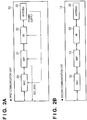
- the first communication unit 13 and the second communication unit 14 shown in Fig. 1 will be explained with reference to Figs. 2A and 2B .
- Each of MACs (Medium Access Controllers) 20 and 30 manages a medium access layer.
- Each of BBPs (Base Band Processors) 21 and 31 has a communication signal processing function such as error correction coding, decoding, and modulation/demodulation.
- Each of RF (Radio Frequency) blocks 22 and 32 processes a baseband signal in the carrier frequency band.
- Each of antennas 23 and 33 transmits/receives a modulated signal of the carrier frequency band in a wireless zone.
- the first communication unit 13 operates using power supplied by electromagnetic induction from an external device (e.g., another communication terminal) or power supplied from itself(control unit 11). Electromagnetic induction is caused using the antenna 23. If the first communication unit 13 operates using only power supplied by electromagnetic induction, the transmission speed is expected to be lower. Hence, the first communication unit 13 may operate using even power supplied from itself as needed.
- the first communication unit 13 When operating by power externally supplied by electromagnetic induction, the first communication unit 13 functions as a storage (also called an RFID or a tag) to passively write or read data. When operating by power supplied from itself, the first communication unit 13 functions as a reader/writer to actively write or read data.
- the first communication unit 13 has a signal output SET_RFID to set the BBP 21 to a storage or reader/writer. When the output level is L (low level), the first communication unit 13 functions as a storage. When the output level is H (high level), the first communication unit 13 functions as a reader/writer.
- the control unit 11 causes the communication terminal 10 to function as a host or a device (a device is controlled by a host) based on the output result of the signal SET_RFID, as will be described later in detail.
- the communication terminal 10 thus performs communication using the second communication unit 14 in one of the communication modes.
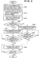
- FIG. 1 An example of the operation of the communication terminal 10 shown in Fig. 1 will be described next with reference to Fig. 3 .
- An example will be described here, in which two communication terminals 10, that is, the communication terminal 10 and another communication terminal (communication partner terminal) communicate with each other.
- the processing starts when the first communication unit 13 of the communication terminal 10 receives power supplied from another communication terminal (to be referred to as a communication partner terminal hereinafter) and starts up(activate) (S300).
- the first communication unit 13 is sometimes started up by the control unit 11, as described above. However, the following explanation will be made assuming that the first communication unit 13 starts up upon receiving power from the communication partner terminal.
- the first communication unit 13 is first connected to the communication partner terminal (S310).
- the connection is done by transmitting device information of the communication terminal 10 to the communication partner terminal.
- the first communication unit 13 When the connection is completed, the first communication unit 13 starts up the second communication unit 14. The first communication unit 13 also notifies the control unit 11 that it is started up by the communication partner terminal (S320). This notification is sent using the signal SET_RFID.
- the control unit 11 determines based on the output result of the signal SET_RFID whether the first communication unit 13 is set on the storage side or reader/writer side. If the first communication unit 13 is on the storage side (YES in step S330), the control unit 11 causes the communication terminal 10 to function as a device (S340). This allows the communication partner terminal to use the communication terminal 10 as a storage.
- the communication terminal 10 causes the control unit 11 to determine whether a data transmission request from the communication partner terminal exists (S350).
- the data transmission request is received via the second communication unit 14.
- the communication terminal 10 transmits data to the communication partner terminal.
- the communication terminal 10 also receives data in some cases, as a matter of course.
- step S350 the control unit 11 transmits data stored in the storage unit 12 to the communication partner terminal via the second communication unit 14 in cooperation with the storage unit 12 (S360).
- the control unit 11 determines based on a response from the communication partner terminal whether the data transmission has ended. If the data transmission has ended (YES in step S370), the communication terminal 10 ends the processing. If the data transmission still continues (NO in step S370), the communication terminal 10 executes the process in step S360 again.
- step S330 Upon determining in step S330 that the first communication unit 13 is not set on the storage side, that is, the first communication unit 13 is set on the reader/writer side (NO in step S330), the control unit 11 causes the communication terminal 10 to function as a host (S380). This allows the communication partner terminal to use the communication terminal 10 as a host.
- control unit 11 determines whether a data transmission request to the communication partner terminal exists (S390).
- the data transmission request is done based on, for example, a user instruction to the communication terminal 10.
- the communication terminal 10 transmits data to the communication partner terminal.
- the communication terminal 10 also receives data in some cases, as described above.
- step S390 If a data transmission request exists (YES in step S390), the control unit 11 transmits data stored in the storage unit 12 to the communication partner terminal via the second communication unit 14 in cooperation with the storage unit 12 (S360). After that, if the data transmission has ended (YES in step S370), the communication terminal 10 ends the processing.
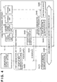
- the communication partner terminal starts up the first communication unit of its own (S400).
- the first communication unit 13 of the communication terminal 10 receives power supplied by electromagnetic induction (S410).
- the first communication unit 13 of the communication terminal 10 starts up as a storage (S420).
- the first communication unit 13 of the communication terminal 10 returns, to the communication partner terminal, a response representing that it has started up as a storage, thereby establishing connection to the communication partner terminal (S430).
- the first communication unit 13 of the communication terminal 10 requests the second communication unit 14 to start up, and notifies the control unit 11 that the first communication unit 13 has started up as a storage (S440).
- This notification is sent using the signal SET_RFID, as described above. For example, when the first communication unit 13 has started up as a storage, the output level of the signal SET_RFID changes to L (low level).
- the second communication unit 14 of the communication terminal 10 starts up (S450).
- the control unit 11 causes the communication terminal 10 to function as a device based on the output result of the signal SET_RFID (S460).
- the communication partner terminal starts up the second communication unit of its own (S470). Then, the communication terminal 10 and the communication partner terminal perform data communication (S480).
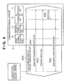
- step S480 of Fig. 4 will be described with reference to Figs. 5 and 6 .
- the communication partner terminal notifies the control unit 11 of the communication terminal 10 that data write will be performed (S500). This notification is sent via the second communication unit 14.
- the communication partner terminal transmits write data (S510).
- the communication terminal 10 receives the write data via the second communication unit 14, and causes the control unit 11 to write the data in the storage unit 12 (S520).
- the communication terminal 10 returns a response (write complete) to the communication partner terminal via the second communication unit 14 (S530).
- the communication partner terminal notifies the control unit 11 of the communication terminal 10 that data read will be performed (S600). This notification is sent via the second communication unit 14.
- the communication terminal 10 causes the control unit 11 to read out data from the storage unit 12 (S610), and transmits the readout data to the communication partner terminal via the second communication unit 14 (S620).
- the communication partner terminal returns a response (read complete) to the control unit 11 of the communication terminal 10 (S630).
- the communication terminal 10 causes the control unit 11 to transmit a start-up request to the first communication unit 13 (S700).
- the first communication unit 13 starts up using power from itself(S710).
- the first communication unit 13 of the communication terminal 10 starts up as a reader/writer.
- the communication partner terminal starts up the first communication unit of its own (S720).
- the first communication unit of the communication partner terminal transmits a connection request to the communication terminal 10 (S730).
- the communication terminal 10 receives the connection request via the first communication unit 13.
- the communication terminal 10 returns a connection acknowledge response to the communication partner terminal via the first communication unit 13, thereby establishing connection to the communication partner terminal (S740).
- the first communication unit 13 of the communication terminal 10 requests the second communication unit 14 to start up, and notifies the control unit 11 that the first communication unit 13 has started up as a reader/writer (S750).
- This notification is sent using the signal SET_RFID, as described above. For example, when the first communication unit 13 has started up as a reader/writer, the output level of the signal SET_RFID changes to H (high level).
- the second communication unit 14 of the communication terminal 10 starts up (S760).
- the control unit 11 causes the communication terminal 10 to function as a host based on the output result of the signal SET_RFID (S770).
- the communication partner terminal starts up the second communication unit of its own (S780). Then, the communication terminal 10 and the communication partner terminal perform data communication (S790).
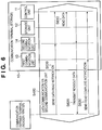
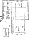
- step S790 of Fig. 7 will be described with reference to Figs. 8 and 9 .
- the communication terminal 10 causes the control unit 11 to notify the communication partner terminal that data transmission will be performed (S800). This notification is sent via the second communication unit 14.
- the communication terminal 10 causes the control unit 11 to read out data from the storage unit 12 (S810), and transmits the readout data to the communication partner terminal via the second communication unit 14 (S820).
- the communication terminal 10 receives a response (data reception complete) from the communication partner terminal via the second communication unit 14 (S830).
- the communication terminal 10 causes the control unit 11 to notify the communication partner terminal that data reception will be performed (S900). This notification is sent via the second communication unit 14.
- the communication partner terminal transmits data via the second communication unit (S910).
- the communication terminal 10 receives the data via the second communication unit 14, and causes the control unit 11 to write the data in the storage unit 12 (S920).
- the communication terminal 10 notifies the communication partner terminal of a response (data reception complete) via the second communication unit 14 (S930).
- the communication mode of the communication terminal 10 using the second communication unit 14 is decided depending on whether the first communication unit 13 is functioning as a reader/writer or a storage. This makes a procedure (e.g., communication mode decision) necessary at the start of communication via the second communication unit 14 more simple than before. It is therefore possible to quickly start communication via the second communication unit 14.
- a communication terminal of the second embodiment has the same arrangement as in Figs. 1 , 2A and 2B described in the first embodiment, and a description thereof will not be repeated.
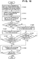
- step S1040 the communication terminal 10 functions as a host although a first communication unit 13 is set on the storage side, unlike the first embodiment.
- step S1080 the communication terminal 10 functions as a device although the first communication unit 13 is set on the reader/writer side, unlike the first embodiment.
- step S1160 An example of the sequence of processing of causing the communication terminal 10 of the second embodiment to operate as a host will be described next with reference to Fig. 11 . Only processing different from Fig. 4 of the first embodiment will be explained. The different point is the process in step S1160. More specifically, as in Fig. 10 , even when the first communication unit 13 is set on the storage side, the communication terminal 10 functions as a host.
- the sequence of data communication in step S1180 is the same as in Figs. 8 and 9 of the first embodiment, and a description thereof will not be repeated.
- step S1270 An example of the sequence of processing of causing the communication terminal 10 of the second embodiment to operate as a device will be described next with reference to Fig. 12 . Only processing different from Fig. 7 of the first embodiment will be explained. The different point is the process in step S1270. More specifically, as in Fig. 10 , even when the first communication unit 13 is set on the reader/writer side, the communication terminal 10 functions as a device.
- the sequence of data communication in step S1290 is the same as in Figs. 5 and 6 of the first embodiment, and a description thereof will not be repeated.
- the second embodiment it is possible to flexibly decide the communication mode of the communication terminal 10 in accordance with the function (reader/writer side or storage side) of the first communication unit 13, in addition to the effects obtained in the first embodiment.
- the present invention can adopt embodiments in the forms of, for example, a system, apparatus, method, program, and storage medium.
- the present invention may be applied to either a system constituted by a plurality of devices, or an apparatus consisting of a single device.
- the present invention includes a case wherein the functions of the aforementioned embodiments are achieved when a software program is directly or remotely supplied to a system or apparatus, and a computer incorporated in that system or apparatus reads out and executes the supplied program codes.
- the program to be supplied in this case is a computer program corresponding to the illustrated flowcharts in the embodiments.
- the program codes themselves installed in a computer to implement the functional processing of the present invention using the computer also implement the present invention. That is, the present invention includes the computer program itself for implementing the functional processing of the present invention.
- the form of program is not particularly limited, and an object code, a program to be executed by an interpreter, script data to be supplied to an OS (Operating System), and the like may be used as long as they have the functions of the program.
- a computer-readable storage medium for supplying the computer program the following media can be used.
- a floppy® disk, hard disk, optical disk, magneto-optical disk, MO, CD-ROM, CD-R, CD-RW, magnetic tape, nonvolatile memory card, ROM, and DVD (DVD-ROM, DVD-R) can be used.
- the user establishes connection to a website on the Internet using a browser on a client computer, and downloads the computer program of the present invention from the website onto a recording medium such as a hard disk.
- the program to be downloaded may be a compressed file including an automatic installation function.
- program codes that form the program of the present invention may be segmented into a plurality of files, which may be downloaded from different websites. That is, the present invention includes a WWW server, which makes a plurality of users download program files required to implement the functional processing of the present invention on their computers.
- a storage medium such as a CD-ROM, which stores the encrypted program of the present invention, may be delivered to the user.
- the user who has cleared a predetermined condition may be allowed to download key information used to decrypt the encrypted program from a website via the Internet. The user executes the encrypted program using that key information to install the program in a computer.
- the functions of the aforementioned embodiments can be implemented when the computer executes the readout program.
- the functions of the aforementioned embodiments may be implemented in collaboration with an OS or the like running on the computer based on an instruction of that program.
- the OS or the like executes some or all of actual processes, which implement the functions of the aforementioned embodiments.
- some or all of the functions of the aforementioned embodiments may be implemented when the program read out from the recording medium is written in a memory equipped on a function expansion board or a function expansion unit, which is inserted into or connected to the computer.
- a CPU or the like equipped on the function expansion board or unit executes some or all of actual processes based on an instruction of that program.
Landscapes
- Engineering & Computer Science (AREA)
- Physics & Mathematics (AREA)
- Theoretical Computer Science (AREA)
- Health & Medical Sciences (AREA)
- Toxicology (AREA)
- Computer Networks & Wireless Communication (AREA)
- General Physics & Mathematics (AREA)
- Signal Processing (AREA)
- Artificial Intelligence (AREA)
- Computer Vision & Pattern Recognition (AREA)
- General Health & Medical Sciences (AREA)
- Electromagnetism (AREA)
- General Engineering & Computer Science (AREA)
- Computer Security & Cryptography (AREA)
- Telephone Function (AREA)
- Near-Field Transmission Systems (AREA)
- Mobile Radio Communication Systems (AREA)
- Communication Control (AREA)
Applications Claiming Priority (2)
| Application Number | Priority Date | Filing Date | Title |
|---|---|---|---|
| JP2008098751A JP5197112B2 (ja) | 2008-04-04 | 2008-04-04 | 通信装置、その制御方法及びプログラム |
| PCT/JP2009/057031 WO2009123340A1 (en) | 2008-04-04 | 2009-03-31 | Communication terminal, computer-readable storage medium, and communication method |
Publications (3)
| Publication Number | Publication Date |
|---|---|
| EP2263323A1 EP2263323A1 (en) | 2010-12-22 |
| EP2263323A4 EP2263323A4 (en) | 2014-11-12 |
| EP2263323B1 true EP2263323B1 (en) | 2018-08-15 |
Family
ID=41135689
Family Applications (1)
| Application Number | Title | Priority Date | Filing Date |
|---|---|---|---|
| EP09728716.3A Not-in-force EP2263323B1 (en) | 2008-04-04 | 2009-03-31 | Communication terminal, computer-readable storage medium, and communication method |
Country Status (4)
| Country | Link |
|---|---|
| US (2) | US9251389B2 (enExample) |
| EP (1) | EP2263323B1 (enExample) |
| JP (1) | JP5197112B2 (enExample) |
| WO (1) | WO2009123340A1 (enExample) |
Families Citing this family (6)
| Publication number | Priority date | Publication date | Assignee | Title |
|---|---|---|---|---|
| JP5197112B2 (ja) * | 2008-04-04 | 2013-05-15 | キヤノン株式会社 | 通信装置、その制御方法及びプログラム |
| US8724551B2 (en) | 2009-11-02 | 2014-05-13 | Sharp Kabushiki Kaisha | Mobile communication system, mobile station apparatus and re-connection method |
| JP5527848B2 (ja) * | 2010-09-27 | 2014-06-25 | 岩崎通信機株式会社 | 近接給電・通信装置 |
| JP5896653B2 (ja) * | 2011-09-06 | 2016-03-30 | キヤノン株式会社 | 画像形成装置、画像形成装置の制御方法、及びプログラム |
| JP5814751B2 (ja) * | 2011-11-10 | 2015-11-17 | キヤノン株式会社 | 通信装置、通信システム、制御方法、通信方法、及びプログラム |
| JP2014082550A (ja) | 2012-10-12 | 2014-05-08 | Canon Inc | 通信装置、通信方法、及びプログラム |
Family Cites Families (17)
| Publication number | Priority date | Publication date | Assignee | Title |
|---|---|---|---|---|
| DE60330507D1 (de) * | 2003-07-22 | 2010-01-21 | Nokia Corp | Lesereinrichtung für einen hochfrequenz-identifikations-transponder mit transponder-funktionalität |
| JP4416077B2 (ja) | 2003-09-30 | 2010-02-17 | ソニー・エリクソン・モバイルコミュニケーションズ株式会社 | 携帯端末装置 |
| WO2005060710A2 (en) * | 2003-12-18 | 2005-07-07 | Altierre Corporation | Wireless display tag unit |
| JP2006067448A (ja) * | 2004-08-30 | 2006-03-09 | Ricoh Co Ltd | 通信装置およびこの通信装置を備えた携帯電子機器 |
| GB0507285D0 (en) | 2005-04-11 | 2005-05-18 | Innovision Res & Tech Plc | Nfc enabled high-speed data |
| US8244179B2 (en) * | 2005-05-12 | 2012-08-14 | Robin Dua | Wireless inter-device data processing configured through inter-device transmitted data |
| US7702821B2 (en) * | 2005-09-15 | 2010-04-20 | Eye-Fi, Inc. | Content-aware digital media storage device and methods of using the same |
| US20070205865A1 (en) | 2006-03-02 | 2007-09-06 | Broadcom Corporation, A California Corporation | Wireless communication device with RFID reader |
| KR101003295B1 (ko) * | 2006-04-26 | 2010-12-23 | 노키아 코포레이션 | 범용직렬버스 연결 |
| US20080010417A1 (en) * | 2006-04-28 | 2008-01-10 | Zeffer Hakan E | Read/Write Permission Bit Support for Efficient Hardware to Software Handover |
| JP5289733B2 (ja) | 2006-07-13 | 2013-09-11 | オリンパスイメージング株式会社 | 燃料電池を用いた携帯端末機器及び携帯端末機器用の燃料電池システム |
| FR2905782B1 (fr) | 2006-09-11 | 2008-12-05 | Inside Contactless Sa | Procede de connexion d'un circuit integre sans contact a un composant nfc. |
| JP5192385B2 (ja) * | 2006-09-28 | 2013-05-08 | 京セラ株式会社 | 携帯無線機 |
| US20100178866A1 (en) * | 2006-11-27 | 2010-07-15 | Nokia Corporation | Power management of a near field communication apparatus |
| US8098598B1 (en) * | 2007-11-27 | 2012-01-17 | Sprint Communications Company L.P. | Emulating a removable mass storage device |
| JP5159396B2 (ja) * | 2008-04-03 | 2013-03-06 | キヤノン株式会社 | 通信装置、その制御方法及びプログラム |
| JP5197112B2 (ja) * | 2008-04-04 | 2013-05-15 | キヤノン株式会社 | 通信装置、その制御方法及びプログラム |
-
2008
- 2008-04-04 JP JP2008098751A patent/JP5197112B2/ja not_active Expired - Fee Related
-
2009
- 2009-03-31 WO PCT/JP2009/057031 patent/WO2009123340A1/en not_active Ceased
- 2009-03-31 EP EP09728716.3A patent/EP2263323B1/en not_active Not-in-force
- 2009-03-31 US US12/866,850 patent/US9251389B2/en not_active Expired - Fee Related
-
2015
- 2015-12-21 US US14/976,279 patent/US10123369B2/en not_active Expired - Fee Related
Non-Patent Citations (1)
| Title |
|---|
| None * |
Also Published As
| Publication number | Publication date |
|---|---|
| US20100330906A1 (en) | 2010-12-30 |
| US9251389B2 (en) | 2016-02-02 |
| JP2009251916A (ja) | 2009-10-29 |
| JP5197112B2 (ja) | 2013-05-15 |
| US20160119965A1 (en) | 2016-04-28 |
| EP2263323A4 (en) | 2014-11-12 |
| WO2009123340A1 (en) | 2009-10-08 |
| EP2263323A1 (en) | 2010-12-22 |
| US10123369B2 (en) | 2018-11-06 |
Similar Documents
| Publication | Publication Date | Title |
|---|---|---|
| US10879960B2 (en) | Communication device | |
| EP2263323B1 (en) | Communication terminal, computer-readable storage medium, and communication method | |
| JP6080548B2 (ja) | 通信装置、情報端末、それらの制御方法、プログラム | |
| CN103533583B (zh) | 通信系统、通信设备、通信方法、及程序 | |
| US10108383B2 (en) | Communication device communicating target data with external device according to near field communication | |
| US9274734B2 (en) | Recording system, non-transitory storage medium storing instructions executable by mobile terminal, and image recording apparatus | |
| JP2009272874A (ja) | 通信装置、通信方法、プログラム、および通信システム | |
| EP1804531B1 (en) | Communication apparatus and electric power control method | |
| JP2010011366A (ja) | 通信システム、通信装置及び通信制御方法 | |
| KR20050040852A (ko) | 통신 시스템 및 방법, 정보 처리 단말기 및 방법, 정보처리 장치 및 방법 | |
| US20130178157A1 (en) | Communication terminal, computer-readable storage medium, and communication method | |
| US9961485B2 (en) | Communication device | |
| JP5462963B2 (ja) | 通信装置、通信装置の制御方法、及びプログラム | |
| JP5655286B2 (ja) | 通信方法、通信システム、サーバおよびプログラム | |
| JP4784189B2 (ja) | 通信システム、情報処理装置および情報処理方法、情報端末装置および情報処理方法、並びにプログラム | |
| CN107425975B (zh) | 通信装置以及由通信装置执行的方法 | |
| JP2019068438A (ja) | 通信装置 | |
| JP2020099098A (ja) | 通信装置 |
Legal Events
| Date | Code | Title | Description |
|---|---|---|---|
| PUAI | Public reference made under article 153(3) epc to a published international application that has entered the european phase |
Free format text: ORIGINAL CODE: 0009012 |
|
| 17P | Request for examination filed |
Effective date: 20101104 |
|
| AK | Designated contracting states |
Kind code of ref document: A1 Designated state(s): AT BE BG CH CY CZ DE DK EE ES FI FR GB GR HR HU IE IS IT LI LT LU LV MC MK MT NL NO PL PT RO SE SI SK TR |
|
| AX | Request for extension of the european patent |
Extension state: AL BA RS |
|
| DAX | Request for extension of the european patent (deleted) | ||
| A4 | Supplementary search report drawn up and despatched |
Effective date: 20141013 |
|
| RIC1 | Information provided on ipc code assigned before grant |
Ipc: G06K 7/10 20060101ALI20141007BHEP Ipc: H04W 76/02 20090101ALI20141007BHEP Ipc: H04W 84/10 20090101ALI20141007BHEP Ipc: H02J 5/00 20060101ALN20141007BHEP Ipc: G06K 17/00 20060101ALI20141007BHEP Ipc: H04B 1/59 20060101ALI20141007BHEP Ipc: H04B 5/00 20060101ALN20141007BHEP Ipc: G06K 19/07 20060101AFI20141007BHEP Ipc: H04B 5/02 20060101ALI20141007BHEP Ipc: G06K 7/00 20060101ALI20141007BHEP |
|
| 17Q | First examination report despatched |
Effective date: 20160614 |
|
| STAA | Information on the status of an ep patent application or granted ep patent |
Free format text: STATUS: EXAMINATION IS IN PROGRESS |
|
| GRAP | Despatch of communication of intention to grant a patent |
Free format text: ORIGINAL CODE: EPIDOSNIGR1 |
|
| STAA | Information on the status of an ep patent application or granted ep patent |
Free format text: STATUS: GRANT OF PATENT IS INTENDED |
|
| RIC1 | Information provided on ipc code assigned before grant |
Ipc: H04B 1/59 20060101AFI20180122BHEP Ipc: G06K 7/10 20060101ALI20180122BHEP Ipc: H04W 88/06 20090101ALN20180122BHEP Ipc: G06F 13/38 20060101ALI20180122BHEP Ipc: G06F 12/00 20060101ALI20180122BHEP Ipc: H04W 72/04 20090101ALI20180122BHEP |
|
| RIN1 | Information on inventor provided before grant (corrected) |
Inventor name: AOKI, NORIHITO |
|
| INTG | Intention to grant announced |
Effective date: 20180222 |
|
| GRAS | Grant fee paid |
Free format text: ORIGINAL CODE: EPIDOSNIGR3 |
|
| GRAA | (expected) grant |
Free format text: ORIGINAL CODE: 0009210 |
|
| STAA | Information on the status of an ep patent application or granted ep patent |
Free format text: STATUS: THE PATENT HAS BEEN GRANTED |
|
| AK | Designated contracting states |
Kind code of ref document: B1 Designated state(s): AT BE BG CH CY CZ DE DK EE ES FI FR GB GR HR HU IE IS IT LI LT LU LV MC MK MT NL NO PL PT RO SE SI SK TR |
|
| REG | Reference to a national code |
Ref country code: CH Ref legal event code: EP Ref country code: GB Ref legal event code: FG4D Ref country code: AT Ref legal event code: REF Ref document number: 1030952 Country of ref document: AT Kind code of ref document: T Effective date: 20180815 |
|
| REG | Reference to a national code |
Ref country code: IE Ref legal event code: FG4D |
|
| REG | Reference to a national code |
Ref country code: DE Ref legal event code: R096 Ref document number: 602009053866 Country of ref document: DE |
|
| REG | Reference to a national code |
Ref country code: NL Ref legal event code: MP Effective date: 20180815 |
|
| REG | Reference to a national code |
Ref country code: LT Ref legal event code: MG4D |
|
| REG | Reference to a national code |
Ref country code: AT Ref legal event code: MK05 Ref document number: 1030952 Country of ref document: AT Kind code of ref document: T Effective date: 20180815 |
|
| PG25 | Lapsed in a contracting state [announced via postgrant information from national office to epo] |
Ref country code: FI Free format text: LAPSE BECAUSE OF FAILURE TO SUBMIT A TRANSLATION OF THE DESCRIPTION OR TO PAY THE FEE WITHIN THE PRESCRIBED TIME-LIMIT Effective date: 20180815 Ref country code: LT Free format text: LAPSE BECAUSE OF FAILURE TO SUBMIT A TRANSLATION OF THE DESCRIPTION OR TO PAY THE FEE WITHIN THE PRESCRIBED TIME-LIMIT Effective date: 20180815 Ref country code: GR Free format text: LAPSE BECAUSE OF FAILURE TO SUBMIT A TRANSLATION OF THE DESCRIPTION OR TO PAY THE FEE WITHIN THE PRESCRIBED TIME-LIMIT Effective date: 20181116 Ref country code: SE Free format text: LAPSE BECAUSE OF FAILURE TO SUBMIT A TRANSLATION OF THE DESCRIPTION OR TO PAY THE FEE WITHIN THE PRESCRIBED TIME-LIMIT Effective date: 20180815 Ref country code: BG Free format text: LAPSE BECAUSE OF FAILURE TO SUBMIT A TRANSLATION OF THE DESCRIPTION OR TO PAY THE FEE WITHIN THE PRESCRIBED TIME-LIMIT Effective date: 20181115 Ref country code: NL Free format text: LAPSE BECAUSE OF FAILURE TO SUBMIT A TRANSLATION OF THE DESCRIPTION OR TO PAY THE FEE WITHIN THE PRESCRIBED TIME-LIMIT Effective date: 20180815 Ref country code: AT Free format text: LAPSE BECAUSE OF FAILURE TO SUBMIT A TRANSLATION OF THE DESCRIPTION OR TO PAY THE FEE WITHIN THE PRESCRIBED TIME-LIMIT Effective date: 20180815 Ref country code: NO Free format text: LAPSE BECAUSE OF FAILURE TO SUBMIT A TRANSLATION OF THE DESCRIPTION OR TO PAY THE FEE WITHIN THE PRESCRIBED TIME-LIMIT Effective date: 20181115 Ref country code: IS Free format text: LAPSE BECAUSE OF FAILURE TO SUBMIT A TRANSLATION OF THE DESCRIPTION OR TO PAY THE FEE WITHIN THE PRESCRIBED TIME-LIMIT Effective date: 20181215 |
|
| PG25 | Lapsed in a contracting state [announced via postgrant information from national office to epo] |
Ref country code: HR Free format text: LAPSE BECAUSE OF FAILURE TO SUBMIT A TRANSLATION OF THE DESCRIPTION OR TO PAY THE FEE WITHIN THE PRESCRIBED TIME-LIMIT Effective date: 20180815 Ref country code: ES Free format text: LAPSE BECAUSE OF FAILURE TO SUBMIT A TRANSLATION OF THE DESCRIPTION OR TO PAY THE FEE WITHIN THE PRESCRIBED TIME-LIMIT Effective date: 20180815 Ref country code: LV Free format text: LAPSE BECAUSE OF FAILURE TO SUBMIT A TRANSLATION OF THE DESCRIPTION OR TO PAY THE FEE WITHIN THE PRESCRIBED TIME-LIMIT Effective date: 20180815 |
|
| PG25 | Lapsed in a contracting state [announced via postgrant information from national office to epo] |
Ref country code: CZ Free format text: LAPSE BECAUSE OF FAILURE TO SUBMIT A TRANSLATION OF THE DESCRIPTION OR TO PAY THE FEE WITHIN THE PRESCRIBED TIME-LIMIT Effective date: 20180815 Ref country code: RO Free format text: LAPSE BECAUSE OF FAILURE TO SUBMIT A TRANSLATION OF THE DESCRIPTION OR TO PAY THE FEE WITHIN THE PRESCRIBED TIME-LIMIT Effective date: 20180815 Ref country code: IT Free format text: LAPSE BECAUSE OF FAILURE TO SUBMIT A TRANSLATION OF THE DESCRIPTION OR TO PAY THE FEE WITHIN THE PRESCRIBED TIME-LIMIT Effective date: 20180815 Ref country code: EE Free format text: LAPSE BECAUSE OF FAILURE TO SUBMIT A TRANSLATION OF THE DESCRIPTION OR TO PAY THE FEE WITHIN THE PRESCRIBED TIME-LIMIT Effective date: 20180815 Ref country code: PL Free format text: LAPSE BECAUSE OF FAILURE TO SUBMIT A TRANSLATION OF THE DESCRIPTION OR TO PAY THE FEE WITHIN THE PRESCRIBED TIME-LIMIT Effective date: 20180815 |
|
| REG | Reference to a national code |
Ref country code: DE Ref legal event code: R097 Ref document number: 602009053866 Country of ref document: DE |
|
| PG25 | Lapsed in a contracting state [announced via postgrant information from national office to epo] |
Ref country code: DK Free format text: LAPSE BECAUSE OF FAILURE TO SUBMIT A TRANSLATION OF THE DESCRIPTION OR TO PAY THE FEE WITHIN THE PRESCRIBED TIME-LIMIT Effective date: 20180815 Ref country code: SK Free format text: LAPSE BECAUSE OF FAILURE TO SUBMIT A TRANSLATION OF THE DESCRIPTION OR TO PAY THE FEE WITHIN THE PRESCRIBED TIME-LIMIT Effective date: 20180815 |
|
| PLBE | No opposition filed within time limit |
Free format text: ORIGINAL CODE: 0009261 |
|
| STAA | Information on the status of an ep patent application or granted ep patent |
Free format text: STATUS: NO OPPOSITION FILED WITHIN TIME LIMIT |
|
| 26N | No opposition filed |
Effective date: 20190516 |
|
| PG25 | Lapsed in a contracting state [announced via postgrant information from national office to epo] |
Ref country code: SI Free format text: LAPSE BECAUSE OF FAILURE TO SUBMIT A TRANSLATION OF THE DESCRIPTION OR TO PAY THE FEE WITHIN THE PRESCRIBED TIME-LIMIT Effective date: 20180815 |
|
| PG25 | Lapsed in a contracting state [announced via postgrant information from national office to epo] |
Ref country code: MC Free format text: LAPSE BECAUSE OF FAILURE TO SUBMIT A TRANSLATION OF THE DESCRIPTION OR TO PAY THE FEE WITHIN THE PRESCRIBED TIME-LIMIT Effective date: 20180815 |
|
| REG | Reference to a national code |
Ref country code: CH Ref legal event code: PL |
|
| PG25 | Lapsed in a contracting state [announced via postgrant information from national office to epo] |
Ref country code: LU Free format text: LAPSE BECAUSE OF NON-PAYMENT OF DUE FEES Effective date: 20190331 |
|
| REG | Reference to a national code |
Ref country code: BE Ref legal event code: MM Effective date: 20190331 |
|
| PG25 | Lapsed in a contracting state [announced via postgrant information from national office to epo] |
Ref country code: CH Free format text: LAPSE BECAUSE OF NON-PAYMENT OF DUE FEES Effective date: 20190331 Ref country code: IE Free format text: LAPSE BECAUSE OF NON-PAYMENT OF DUE FEES Effective date: 20190331 Ref country code: LI Free format text: LAPSE BECAUSE OF NON-PAYMENT OF DUE FEES Effective date: 20190331 |
|
| PG25 | Lapsed in a contracting state [announced via postgrant information from national office to epo] |
Ref country code: BE Free format text: LAPSE BECAUSE OF NON-PAYMENT OF DUE FEES Effective date: 20190331 |
|
| PG25 | Lapsed in a contracting state [announced via postgrant information from national office to epo] |
Ref country code: TR Free format text: LAPSE BECAUSE OF FAILURE TO SUBMIT A TRANSLATION OF THE DESCRIPTION OR TO PAY THE FEE WITHIN THE PRESCRIBED TIME-LIMIT Effective date: 20180815 |
|
| PGFP | Annual fee paid to national office [announced via postgrant information from national office to epo] |
Ref country code: GB Payment date: 20200326 Year of fee payment: 12 |
|
| PG25 | Lapsed in a contracting state [announced via postgrant information from national office to epo] |
Ref country code: MT Free format text: LAPSE BECAUSE OF NON-PAYMENT OF DUE FEES Effective date: 20190331 Ref country code: PT Free format text: LAPSE BECAUSE OF FAILURE TO SUBMIT A TRANSLATION OF THE DESCRIPTION OR TO PAY THE FEE WITHIN THE PRESCRIBED TIME-LIMIT Effective date: 20181215 |
|
| PGFP | Annual fee paid to national office [announced via postgrant information from national office to epo] |
Ref country code: FR Payment date: 20200326 Year of fee payment: 12 |
|
| PGFP | Annual fee paid to national office [announced via postgrant information from national office to epo] |
Ref country code: DE Payment date: 20200528 Year of fee payment: 12 |
|
| PG25 | Lapsed in a contracting state [announced via postgrant information from national office to epo] |
Ref country code: CY Free format text: LAPSE BECAUSE OF FAILURE TO SUBMIT A TRANSLATION OF THE DESCRIPTION OR TO PAY THE FEE WITHIN THE PRESCRIBED TIME-LIMIT Effective date: 20180815 |
|
| PG25 | Lapsed in a contracting state [announced via postgrant information from national office to epo] |
Ref country code: HU Free format text: LAPSE BECAUSE OF FAILURE TO SUBMIT A TRANSLATION OF THE DESCRIPTION OR TO PAY THE FEE WITHIN THE PRESCRIBED TIME-LIMIT; INVALID AB INITIO Effective date: 20090331 |
|
| REG | Reference to a national code |
Ref country code: DE Ref legal event code: R119 Ref document number: 602009053866 Country of ref document: DE |
|
| GBPC | Gb: european patent ceased through non-payment of renewal fee |
Effective date: 20210331 |
|
| PG25 | Lapsed in a contracting state [announced via postgrant information from national office to epo] |
Ref country code: DE Free format text: LAPSE BECAUSE OF NON-PAYMENT OF DUE FEES Effective date: 20211001 Ref country code: GB Free format text: LAPSE BECAUSE OF NON-PAYMENT OF DUE FEES Effective date: 20210331 Ref country code: FR Free format text: LAPSE BECAUSE OF NON-PAYMENT OF DUE FEES Effective date: 20210331 |
|
| PG25 | Lapsed in a contracting state [announced via postgrant information from national office to epo] |
Ref country code: MK Free format text: LAPSE BECAUSE OF FAILURE TO SUBMIT A TRANSLATION OF THE DESCRIPTION OR TO PAY THE FEE WITHIN THE PRESCRIBED TIME-LIMIT Effective date: 20180815 |