EP2263098B1 - Positionsbestimmung von mobilen objekten auf der basis von gegenseitig gesendeten signalen - Google Patents
Positionsbestimmung von mobilen objekten auf der basis von gegenseitig gesendeten signalen Download PDFInfo
- Publication number
- EP2263098B1 EP2263098B1 EP08736808.0A EP08736808A EP2263098B1 EP 2263098 B1 EP2263098 B1 EP 2263098B1 EP 08736808 A EP08736808 A EP 08736808A EP 2263098 B1 EP2263098 B1 EP 2263098B1
- Authority
- EP
- European Patent Office
- Prior art keywords
- location
- positioning
- target object
- probability distribution
- assisting
- Prior art date
- Legal status (The legal status is an assumption and is not a legal conclusion. Google has not performed a legal analysis and makes no representation as to the accuracy of the status listed.)
- Active
Links
Images


Classifications
-
- G—PHYSICS
- G01—MEASURING; TESTING
- G01S—RADIO DIRECTION-FINDING; RADIO NAVIGATION; DETERMINING DISTANCE OR VELOCITY BY USE OF RADIO WAVES; LOCATING OR PRESENCE-DETECTING BY USE OF THE REFLECTION OR RERADIATION OF RADIO WAVES; ANALOGOUS ARRANGEMENTS USING OTHER WAVES
- G01S5/00—Position-fixing by co-ordinating two or more direction or position line determinations; Position-fixing by co-ordinating two or more distance determinations
- G01S5/0009—Transmission of position information to remote stations
- G01S5/0072—Transmission between mobile stations, e.g. anti-collision systems
-
- G—PHYSICS
- G01—MEASURING; TESTING
- G01S—RADIO DIRECTION-FINDING; RADIO NAVIGATION; DETERMINING DISTANCE OR VELOCITY BY USE OF RADIO WAVES; LOCATING OR PRESENCE-DETECTING BY USE OF THE REFLECTION OR RERADIATION OF RADIO WAVES; ANALOGOUS ARRANGEMENTS USING OTHER WAVES
- G01S5/00—Position-fixing by co-ordinating two or more direction or position line determinations; Position-fixing by co-ordinating two or more distance determinations
- G01S5/02—Position-fixing by co-ordinating two or more direction or position line determinations; Position-fixing by co-ordinating two or more distance determinations using radio waves
- G01S5/0252—Radio frequency fingerprinting
- G01S5/02521—Radio frequency fingerprinting using a radio-map
- G01S5/02524—Creating or updating the radio-map
- G01S5/02525—Gathering the radio frequency fingerprints
-
- G—PHYSICS
- G01—MEASURING; TESTING
- G01S—RADIO DIRECTION-FINDING; RADIO NAVIGATION; DETERMINING DISTANCE OR VELOCITY BY USE OF RADIO WAVES; LOCATING OR PRESENCE-DETECTING BY USE OF THE REFLECTION OR RERADIATION OF RADIO WAVES; ANALOGOUS ARRANGEMENTS USING OTHER WAVES
- G01S5/00—Position-fixing by co-ordinating two or more direction or position line determinations; Position-fixing by co-ordinating two or more distance determinations
- G01S5/16—Position-fixing by co-ordinating two or more direction or position line determinations; Position-fixing by co-ordinating two or more distance determinations using electromagnetic waves other than radio waves
-
- G—PHYSICS
- G01—MEASURING; TESTING
- G01S—RADIO DIRECTION-FINDING; RADIO NAVIGATION; DETERMINING DISTANCE OR VELOCITY BY USE OF RADIO WAVES; LOCATING OR PRESENCE-DETECTING BY USE OF THE REFLECTION OR RERADIATION OF RADIO WAVES; ANALOGOUS ARRANGEMENTS USING OTHER WAVES
- G01S5/00—Position-fixing by co-ordinating two or more direction or position line determinations; Position-fixing by co-ordinating two or more distance determinations
- G01S5/02—Position-fixing by co-ordinating two or more direction or position line determinations; Position-fixing by co-ordinating two or more distance determinations using radio waves
- G01S5/0284—Relative positioning
Definitions
- the invention relates generally to techniques for determining a location estimate for a first target object in an environment which also comprises a second target object and wherein at least one location-dependent physical quantity is influenced by the location of the second target object and wherein an initial location estimate for the second target object is determined based on a data model of the at least one location-dependent physical quantity and on observations on the at least one location-dependent physical quantity.
- tags are electronic devices whose principal purpose is to assist estimating the location of more valuable entities co-located with the tags, such as humans or pieces of equipment.
- the tags are operable to measure signal strengths from one or more base stations in a Wireless Local Area Network (WLAN) and to relay the signal strength measurements to a positioning application.
- WLAN Wireless Local Area Network
- the term positioning engine refers to a combination of the positioning application and the computer apparatus which executes the positioning application.
- the tags In order to estimate a tag's position with sufficient accuracy and reliability, which typically means determining the room where tag is located, the tags should repeat signal strength measurements with sufficient repetition rate, such as with 10-second intervals or less and with sufficient scope, such that one observation (scan of measurable frequencies/channels) includes signal strength measurements from five or more base stations.
- a large number of measurements is required because signal strengths are subject to strong random fluctuations even in cases where the tag stands perfectly still. The random fluctuations are typically caused by radio-frequency interference and persons or objects moving in the environment, thus causing temporary attenuation in signal propagation. Because of the fluctuations, some of the tag's observations are incomplete, which means that signals from distant or heavily attenuated base stations could not be measured. An observation which lacks signal strength measurements from several base stations may result in gross positioning errors. Such errors are best eliminated by observing several base stations with a high repetition rate.
- One strategy for extending battery lifetime is to enable the tag to spend most of the time in a sleep mode wherein most of its circuitry is shut off.
- the tag's normal operation is resumed in response to a timer alert, motion detection by a motion sensor, or the tag may have a pushbutton for that purpose.
- the tag wakes up for a scanning operation, it sends a probe request message to one WLAN channel at a time and remains on that channel for some time in order to receive responses from the base stations.
- Each base station which serves the channel on which the probe request message was sent and which is able to receive the message, responds by sending a probe respond message.
- the tag If the tag is able to receive a base station's probe respond message, it is able to measure that base station's signal strength in the place where the tag is located. After scanning all pre-configured channels, the tag compiles the signal strength measurements from all base stations and sends the compiled signal strength measurements to the positioning engine which determines or updates the tag's location estimate. After this, the tag re-enters sleep mode.
- the sleep mode is an effective strategy for extending the tag's battery life, but it causes problem in finding the tag during sleep mode.
- Another positioning problem is caused by the fact that the bandwidth requirements of WLAN networks or some sections of them may be adequately covered by one or two base stations but such a small number of observable base stations is insufficient for accurate and reliable positioning.
- the tags can be positioned by using signals of base stations which exist for the sake of communication, it is not uncommon that existing WLAN networks must be complemented by adding and/or relocating base stations to meet the requirements of accurate and reliable positioning.
- a further problem is that the effect of the added and/or relocated base stations is difficult to predict a priori, and the base station placement tends to require experimentation which in turn requires labour-intensive recalibration of the data model.
- a tag's measurements may be more or less permanently hindered by obstacles. For instance, a tag put in a metal locker may not even attach to any base stations, which prevents it from sending its observations even if the tag is able to make observations. Such a tag may be completely lost until it is taken out from the metal locker.
- a tag may be in a place which has no WLAN network coverage.
- the network may suffer from design errors and or malfunctioning base stations which cause "dead spots", ie, spots that are not adequately covered by any of the base stations.
- the tag may be accidentally or intentionally moved outside the network coverage area.
- a tag may be attached to a patient in a mental hospital and the patient may try to escape the hospital by leaving the building and moving outside the hospital network.
- tags may be used to locate firefighters entering a building in fire, wherein wireless devices carried by the firefighters form an ad-hoc network which is connected to a few fixed base stations residing in fire trucks parked around the building.
- wireless devices near the fire trucks communicate to the base stations directly while other devices deeper in the building communicate via other devices.
- An object of the invention is to develop a method, an apparatus and a software product so as to alleviate one or more of the problems identified above.
- the object of the invention is achieved by aspects of the invention as defined in the attached independent claims.
- An aspect of the invention is a method for determining a location estimate for a first target object in an environment which also comprises a second target object and wherein at least one location-dependent physical quantity is influenced by the location of the second target object.
- the method comprises:
- a positioning engine which is a data processing apparatus specially adapted to perform the computations in the above-described method.
- a computer program product for a data processing system wherein execution of the computer program product in the data processing system causes the data processing system to implement the above-described positioning engine.
- the target objects are something whose location estimates are to be determined.
- a non-exhaustive list of exemplary target objects includes humans, such as firefighters, miners, medical personnel, patients, children or any other kind of persons whose mobility needs to be monitored or restricted.
- the list or potential target objects further includes equipment, instruments, shopping carts, or the like.
- the target objects are able to move or be moved in an environment which exhibits at least one physical quantity which is influenced by the location of the second target object.
- the signalling devices associated with the first and second target objects may be similar or different devices.
- the first target object is the target object whose location estimate is to be determined, while the second target object is the one whose operation and signalling is used to assist locating the first target object.
- the at least one location-dependent physical quantity may be any physical value that can be observed and wherein the observed value is influenced by the location of the second target object.
- the physical quantity is based on radio signals and the observed value may be, but is not limited to, "strength of a radio signal transmitted by base station A when observed by the second target object", or "time difference between transmission and arrival of a radio signal transmitted by the second target object and received by base station B".
- the location-dependent physical quantity indicates visibility of a certain object to a certain observer.
- the physical quantity may be based on an infrared transmitter at a known location, and the observed value could be "indication of whether infrared signals transmitted by the infrared transmitter are visible to the second target object or not (yes/no)".
- Another example of an observation on a visibility-based quantity is "estimated distance and direction of a target object from a camera placed at a known location", wherein the target object is identified from a video signal using image recognition and the distance estimate is based on prior knowledge of physical dimensions of the target object.
- the environment comprises a communication network, such as WLAN, wherein communication is effected using signals which have one or more location-dependent signal parameters, which are typically radiometric signal quality values, such as signal strength, signal-to-noise ratio, bit error rate/ratio, timing advance or the like.
- WLAN networks typically comprise multiple base stations and each measurable signal parameter for a signal transmitted or received by a base station can be interpreted as a separate location-dependent physical quantity.
- a benefit of this embodiment is that the signalling devices associated and co-located with the target objects only need to observe signal strength in the WLAN network, which WLAN transceivers routinely do, although not for positioning purposes.
- the influence of the target objects' location on the physical quantity is modelled by means of a data model.
- the data model is operatively coupled with a positioning engine which determines location probability distributions for the target objects.
- the data model is a probabilistic model comprising probability distributions for observations on the physical quantity at several locations in the environment.
- the data model comprises locations and properties of base stations and information of obstacles affecting radio signals transmitted or received by the base stations.
- the data model comprises locations of video cameras and a database containing information about target objects needed for image recognition. It should be apparent to a person skilled in the art that the exact nature of the physical quantity or the data model is not essential for this invention, as long as the influence of the target objects' location on the quantity can be modelled by the data model with reasonable accuracy.
- the positioning engine needs to receive one or more observations on the at least one physical quantity influenced by the second target object.
- the observations are made and sent to the positioning engine by a sensing device co-located with the second target object.
- the sensing device may be a WLAN transceiver which makes observations on WLAN signals transmitted by one or more WLAN base stations, and sends the observed signal values to the positioning engine.
- one or more base stations make observations on signals transmitted by a device co-located with the second target object.
- observations are generated and sent to the positioning engine by a system receiving live video signal from a camera at a known location and wherein the observations are based on image recognition.
- the positioning engine makes a quantity observation set from the received observations.
- the quantity observation set may comprise a single observation, or it may be a statistical summary of several observations made at different times and/or received from different sources.
- making the quantity observation set may involve using sophisticated time-series analysis techniques to determine a representative sample from a sequence of observations.
- making the quantity observation set may also utilize prior knowledge about the target objects, devices used for making the observations, and/or environment conditions. For instance, the positioning engine may compensate differences between sensing devices by using a normalization function specific to the sensing device type, or take into account changes in power levels of quantity-related base stations. It should be apparent to a person skilled in the art that the exact nature of methods for making the quantity observation set is not essential for this invention, as long as the quantity observation set is based on the received observations and therefore reflects the location of the second target object.
- the exact location of the first target object in not known precisely beforehand.
- any possible prior information regarding to the location of the first target object is expressed as the first location probability distribution.
- every location is considered equally probable whereby the first location probability distribution is flat.
- the first location probability distribution is based on expected locations of the first target object. For instance, in case the first target object is a hospital patient, he/she can be expected to spend most of his/her time in his/her own room, so the initial probability for the room can be a little bit higher than for other locations.
- the first probability distribution is based on quantity observations and the data model just like the second location probability distribution.
- location estimation is a recursive process, wherein the first location probability distribution is based on the updated first location probability distribution determined during the previous recursion step.
- a key element of the present invention is the positioning-assisting signal which is sent by at least one of the signalling devices and received by another signalling device, wherein the recipient of the positioning assisting-signal makes a positioning-assisting observation set from the received positioning assisting-signal and sends the positioning-assisting observation set to the positioning engine.
- the positioning-signal can be transmitted by using any of a wide variety of techniques. For instance, radio, microwave, audio, ultrasound, light, infrared or ultraviolet communication can be used.
- the signalling devices may be based on completely different measurement techniques.
- the positioning-signal can be sent from the first signalling device to the second signalling device or vice versa, as long as the positioning-assisting observation set reflects the mutual proximity of the signalling devices.
- the positioning-assisting signal is based on the same technology as the location-dependent quantity.
- the positioning-assisting signal and the location-dependent quantity can both be based on WLAN signals in which case the same WLAN transceiver can be used as a signalling device and as a sensing device observing the quantity, and also as sending means for sending the observations to the positioning engine.
- the positioning-assisting signal is totally independent from the quantity observations and/or the method used to communicate with the positioning engine.
- the quantity observations may be based on infrared signals while the positioning-assisting signal is transmitted using ultrasound frequency and the observation set is sent to the positioning engine using a GPRS link.
- the positioning-assisting observation set is utilized by the positioning engine when determining an updated first location probability distribution for the first target object.
- determining the updated first location probability distribution comprises determining an additional location probability distribution based on the positioning-assisting observation set and the second location probability distribution for the second target object.
- determining the additional location probability distribution comprises using a signal propagation model to estimate the likelihood of the positioning-assisting observation set for hypothetical locations of the first and second target object.
- the updated first location probability distribution is determined as a subset of the first location probability distribution wherein some of the locations indicated possible by the first location probability distribution are rejected based on proximity constraints identified from the positioning-assisting observation set. For instance, in case the positioning-assisting signal indicates very close proximity of target objects, the positioning engine can set a zero or very low probability for each location distant from the estimated location of the second target object.
- the positioning engine estimates the location of the first target object using the updated first location probability distribution.
- the location estimate is a single point, which can be determined as the most probable location, a probability-weighted average of all possible locations, the central of the most probable high-probability region, or using any other method for selecting a single location based on a location probability distribution.
- the positioning engine may return one or more points and a quality value for each returned point indicating the likelihood that the point represents the correct location of the first target object.
- the location estimate indicates one or more high-probability zones, wherein the zones are specified beforehand and each zone indicates a region within the environment.
- the location estimate can be anything that can be derived from a location probability distribution, and a person skilled in the art should understand that the exact nature of the location estimate is not essential for this invention.
- the positioning engine triggers one or more physical actions based on the location estimate for the first target object.
- the physical action comprises outputting the location estimate to a physical output device, such as a display or a printer, and/or to a physical storage, such as a database or a file.
- the positioning engine may trigger an alarm in case the location estimate fulfils some pre-determined alarming conditions. For instance, in a mental hospital a patient's location estimate pointing to a location outside allowed area may trigger a "patient escaping" alarm. It should be apparent to those skilled in art that the exact nature of the triggered physical action is not essential for this invention.
- the invention is partially based on the idea that the requirement for accurate and reliable tag positioning varies over time. In most tag positioning applications, the tag's position is virtually irrelevant when nobody needs to find the tag or the object/person co-located with it. Conversely, the need for the tag's position estimate to be accurate and reliable is highest when there is a need to find or locate the tag.
- the invention is also based on the idea that determination of the location estimate for the target object can be improved by sending and observing positioning-assisting signals between a first target object and a second target object. In such situations it is possible to improve positioning of a first target object by using observations from another location occupied by a second target object.
- the mutual positioning-assisting signals sent from one mobile target object and received by another mobile target object provides new type of information which has not been utilized in prior art positioning systems.
- the first target object is the one that particularly needs to be located
- the second target object (or more precisely: the second signal transceiver associated and co-located with the second target object) is one which is at least temporarily used to assist positioning the first target object.
- the transceivers associated with the first and second target objects can be similar and their location estimates can be determined by using similar techniques, but in a typical application example the first transceiver is a low-cost tag while the second signal transceiver is a more comprehensive communications apparatus, such as a portable or palmtop computer.
- the positioning engine and the data model may be installed in some or all of the target objects' co-located and associated signalling devices, such as powerful portable computers.
- a centralized positioning engine which assembles observations in respect of several target objects typically has access to more available information and is subject to fewer resource constraints, such as battery, processing and memory resources.
- a centralized positioning engine which assembles observations in respect of several target objects can also coordinate the movements of persons carrying the signalling devices in cases wherein a target object must be searched quickly. For instance, the centralized positioning engine may send the signalling devices explicit motion instructions or current positioning data in respect of other signalling devices participating in the search.
- a controller is used to define an operation logic for sending the positioning-assisting signal and at least one positioning-assisting signal is sent in response to a transmission request from the controller.
- the positioning assisting signal may be sent in response to a preceding positioning-assisting signal sent by the first signalling device.
- the controller may define an operation logic for sending the preceding positioning-assisting signal and the preceding positioning-assisting signal may be sent in response to a transmission request from the controller.
- the controller may further adjust the operation logic based on the positioning-adjusting observation set, wherein adjusting the operation logic may comprise adjusting a time interval between consecutive transmission requests.
- the second signalling device responds to the preceding positioning-assisting signal by sending the positioning signal only when there is an indicated need to assist positioning of the first target object. For instance, the need may be indicated by the user of the second signalling device or the operator of the positioning engine.
- reception of the positioning-assisting signal may trigger sending further positioning-assisting signal(s).
- the reception of the positioning-assisting signal serves as an indication that the target object associated with the signalling device is being searched and it should assist the search by sending further positioning-assisting signal(s).
- the first signalling device is a low-cost tag which suffers from at least one of the positioning problems described in the background section of this patent specification
- the second signalling device is a palmtop computer or personal digital assistant ("PDA") carried by a person who has indicated a need to find the tag.
- PDA personal digital assistant
- the latest location estimate for the tag reported by the positioning engine can be displayed on the PDA so that its user can move towards the estimated location and approach the tag, although the estimate is not exactly correct.
- the tag spends most of its time in power-saving mode, and it can be scheduled to activate after some interval of time.
- This embodiment exhibits the additional problem that although positioning-assisting signalling between the tag and the PDA can be used to improve the location estimate for the tag, the location estimate update interval is fully determined by the wake-up interval of the tag, which may be so long that the PDA user searching the tag will be frustrated.
- a definite advantage can be achieved by implementing the controller and the operation logic in the tag, preferably in its firmware, so that the tag's scheduled wake-up time is adjusted according to the operation logic.
- the controller sends a transmission request to a signalling module which causes transmission of a preceding positioning-assisting signal.
- the PDA receives this signal and responds by sending a positioning-assisting signal because PDA user has indicated a need to assist positioning of the tag, wherein the positioning-assisting signal received by the tag serves as a direct indication for the controller that the tag is being searched.
- the controller can then adjust the operation logic so that the wake-up interval of the tag is shortened, and this affects the time interval between consecutive transmission requests accordingly. This way the location estimates can be updated much more frequently as the PDA approaches the tag and the PDA user will find the tag faster.
- the controller and the operation logic may be used to synchronize positioning-assisting signalling between two or more low-cost tags which all spend most of their time in power-saving mode, which is why they are unable to send or receive positioning-assisting signals at that time.
- all tags follow the same operation logic, they can be scheduled to wake-up simultaneously, to send the positioning-assisting signals and to stay in receiving mode for a while to capture possible positioning-assisting signals from nearby tags.
- positioning accuracy and/or efficiency for all tags can be improved significantly because the number of mutual observations and information available to the positioning engine increases according to the number of active tags within the environment.
- the data model is a probabilistic data model which indicates a probability distribution for the at least one location-dependent physical quantity for each of several locations in the environment.
- a benefit of the probability distribution over some other models which only indicate a single representative parameter value is that the probabilistic data model can provide more information than a single numerical value, such as an expected signal strength. For instance, several base stations may have nearly identical representative signal strengths at some location in the environment, but in some cases such base stations can be distinguished from one another by virtue of different probability distributions.
- a probabilistic data model is also relatively robust in cases wherein the observations are ambiguous or contradictory.
- the commonly-owned patent applications and patents listed at the end of the description of the present invention disclose various techniques for determining the target object's location on the basis of the data model and the observations made by the target object's co-located signal transceiver.
- the step of determining the location probability distribution for a target object proceeds along the following phases. First the positioning engine determines a probability for an observation of the at least one location-dependent physical quantity at a hypothetical location of the target object, based on the probability distribution for the at least one location-dependent physical quantity indicated by the probabilistic data model at the target object's hypothetical location. Then the positioning engine determines a density of the location probability distribution at the target object's hypothetical location based on the probability for the observation of the at least one location-dependent physical quantity at the target object's hypothetical location.
- the target object's location but also the at least one location-dependent physical quantity, such as signal strength, is indicated as a probability distribution.
- a benefit of the probabilistic model over models which merely indicate an expected signal value at a number of calibrated locations is that probability distribution lends itsetf to weight-ranking calculations with relative ease.
- the signalling devices rarely if ever observe signal strengths or other physical quantities perfectly identical with those indicated by the data model. If the real-life environment deviates from the model and the model merely indicates one value for several locations, or a set of values, such as a spectral snapshot, the location that best matches with the observations is outputted as the location estimate, and other location candidates are simply omitted.
- the positioning engine monitors a location estimate for one or more second target objects and progress of the position-assisting observation sets as a function of the location estimate for the one or more second target objects and wherein the positioning engine further sends the one or more second target objects instructions for changing location based on the progress of the position-assisting observation sets.
- This embodiment is particularly useful in situations wherein the first target object must be located as soon as possible and all available second target objects are instructed to search the first target object.
- the first target object may be a person missing or in a hazardous situation and any available persons carrying palmtop computers or other suitable signalling devices are instructed to search for the missing person.
- the position engine PE preferably keeps track of the motion of the second target object(s) and the progress of the position-assisting observation sets.
- the position engine PE sends movement instructions based on the monitored progress of the position-assisting observation sets. For instance, if some sections of the environment has been adequately searched and the position-assisting observation sets were consistently very low, this indicates that the first target object is not in or near the section already searched. Accordingly the second target objects should be instructed to move elsewhere. Likewise, if the position-assisting observation sets are strong, this indicates that the first and second target object(s) are relatively close to one another and search should be concentrated in that section of the environment.
- Figures 1 through 5 demonstrate the operating principle of the invention by means of gradually progressing schematic illustrations.
- Figures 1 through 5 are based on the assumption that the first target object is a low-cost tag which suffers from the positioning problems described in the background section of this patent specification, while the second target object is a palmtop computer or personal digital assistant ("PDA") having more extensive signal measurement capabilities.
- PDA personal digital assistant
- a typical PDA's battery is bigger and charged more frequently than a tag's battery, the PDA has more processing power and since it has other uses apart from positioning, it can be provided with more advanced signal processing circuitry.
- the inventive principle can be used to enhance positioning of a first target object by means of observations of a second target object even if the two target objects are equally capable, and the assumption that target object 1 is a tag while target object 2 is a PDA only relates to a typical application example but is not an essential feature of the invention.
- Figure 1 shows a hypothetical environment wherein a position estimate in respect of a positioning tag is ambiguous.
- Reference sign T01 denotes a first target object T01, which is associated with a co-located first signal transceiver STR1, which represents an implementation of a signalling device.
- the fact that a target object n is associated with a respective signal transceiver n is best described via an example.
- the target object which is the real entity of interest, such as a person, animal, valuable instrument, apparatus, document folder or the like, may be located by locating the signal transceiver whose communication identity in the environment (eg WLAN or other network) is associated with the target object.
- the fact that the target object n is co-located with the respective signal transceiver n means that if the signal transceiver n is found, its associated target object n can be found as well.
- the target object can be the signal transceiver itself. But in some positioning applications valuable information may be gained by modelling the target objects' motion with motion models such as those disclosed in commonly owned patent applications EP 1 796419 / US 2007/0149216 .
- the signal transceiver STR1 associated with the first target object T01 is a positioning tag.
- the tag TO1/STR1 moves or can be moved in an environment in which communication signals are transmitted which have one or more location-dependent parameters, such as signal strength.
- location-dependent parameters such as signal strength.
- signals are transmitted by WLAN base stations BS1, BS2 at fixed locations.
- Figure 1 shows two exemplary base stations but reliable positioning in complex environments requires more than two base stations.
- the location-dependence of the signal parameters is modelled with a probabilistic data model DM of the environment. Although the base stations are fixed, their precise locations need not be known. Instead the probabilistic data model DM indicates a probability distribution for the location-dependent parameters at several locations in the environment.
- the probability distribution for the location-dependent parameters can be determined via any combination of applicable techniques, such as calibration, propagation modelling (ray tracing) and/or interpolation/extrapolation from known locations.
- sample point refers to a location at which the probability distribution for the location-dependent parameters is known.
- the positioning engine may utilize any available prior information on the location of the first target object in form of a location probability distribution LPD1.
- This prior information is not mandatory, however. In case nothing is known or assumed beforehand, every location is considered equally probably, which can be expressed as a flat location probability distribution.
- location probability distributions for each target object are based on observations on location-dependent quantities, which will yield the best positioning accuracy. Therefore the example scenarios illustrated in Figures 1 to 5 are based on the assumption that the initial location probability distribution for the first target object is determined using observations on base station signals.
- the target object TO1/STR1 observes the location-dependent parameters of the communication signals from the base stations and relays its observations to a positioning apparatus, called positioning engine PE.
- the positioning engine PE uses the target object's observations and the probabilistic data model DM to determine a location probability distribution LPD1 for the target object TO1/STR1.
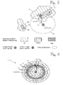
- Reference sign AT denotes an association table that links any target object to its associated and co-located transceiver. Techniques for setting up and maintaining the positioning engine PE and the probabilistic data model DM are disclosed in the reference documents listed at the end of this specification and particularly in WO03/102622 .
- the location-dependent parameters such as signal strength from base station BSn
- a signal strength of x would imply a circle of some radius y around the base station BSn.
- building infrastructure distorts the signal strength-versus-distance dependency and the target object's location, as estimated in the form of the location probability distribution LPD1, typically has an irregular shape.
- the location probability distribution LPD1 has two local peaks which are denoted by reference signs 13A and 13B. The local peaks are surrounded by moderate-probability areas 12A and 12B, which in turn are surrounded by low-probability areas 11 A and 11 B.
- any non-shaded area has a virtually zero probability, ie, a probability lower than some epsilon value, to be the target object's location.
- the presence of multiple peaks makes the position estimate ambiguous.
- probability or location relates to apparent probability or location as seen from the point of view of the positioning engine PE, because of the random fluctuations discussed in the background section of this patent specification.
- the true locations of the target objects are shown in Figures 1 through 5 only to facilitate description of the invention, but the positioning engine PE does not know the target objects' true locations.
- the random fluctuations have the consequence that the true location of the tag TO1/STR1 does not reside in either of the high-probability areas 13A, 13B.
- Figure 2 shows the environment shown in Figure 1 wherein positioning is based on observations made by a second target object which in this example is assumed to be a palmtop computer or PDA. Because the PDA T02 has better signal parameter observation capabilities than the tag T01 had, the location probability distribution LPD2 for the second target object T02 is simpler than the location probability distribution LPD1 for the first target object T01 shown in Figure 1 . There is only one peak area 23 which is surrounded by a moderate-probability area 22 and a low-probability area 21, and the true location of the PDA T02 resides in the high-probability area 23.
- Figure 3 illustrates how positioning ambiguity in respect of the first target object T01 can be reduced or eliminated by using observations of the second target object T02.
- Reference numeral 33 denotes a positioning-assisting signal sent by target object T02 and received by target object TO1.
- Figure 3 shows the two-peaked location probability distribution LPD1 for the first target object TO1 which was described in connection with Figure 1 .
- Figure 3 is based on a simplistic assumption, which will be discarded later, that the position of the second target object T02 (such as a PDA) can be determined accurately as a single point, denoted by reference numeral 31.
- FIG. 3 shows the perimeter 32 as a circle or ellipse but the inventive principle is not restricted to any particular shape.
- the perimeter 32 effectively reduces the positioning ambiguity in respect of the tag T01 because the position of the tag T01 is restricted by both its own location probability distribution LPD1 and the perimeter 31.
- LPD1 location probability distribution
- Figure 4 shows how the perimeter shown in Figure 3 can be generalized to an additional location probability distribution which can be used as additional information for reducing positioning uncertainty. Instead of a perimeter 32 indicating points of maximum probability, Figure 4 shows an additional location probability distribution ALPD which comprises a high-probability zone 43 of areas, two medium-probability zones 42 and two low-probability zones 41. Specific embodiments for determining the addition location probability distribution will be discussed further in this document.
- communication between the target objects T01, T02 is used to assist positioning.
- the second target object T02 PDA
- Such signalling is denoted by reference numeral 33 and referred to by the term "positioning-assisting signal” because these signals are sent specifically to assist positioning.
- the positioning-assisting signal 33 sent by the PDA T02 and observed by the tag T01 yields the additional location probability distribution ALPD schematically shown in Figure 4 .
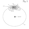
- Figure 5 shows how positioning uncertainty of target objects can be reduced by using a positioning-assisting signal sent from one target object to another.
- Figure 5 shows an updated location probability distribution LPD1' for the tag T01 which is determined by combining the first probability distribution LPD1 for the tag T01 (shown in Figure 1 ) and the additional location probability distribution ALPD (see Figure 4 ) determined on the basis of the positioning-assisting signal from the PDA T02 and observed by the tag T01.
- a simple but effective way to combine the probability distribution is to multiply the probabilities for the locations and to normalize the results of the multiplication, such that the sum or integral over the probabilities is one. Multiplication followed by normalization is not the only way to combine the probability distributions, however.
- the tag's updated location probability distribution LPD1' comprises a high-probability area 53, surrounded by a medium-probability area 52 and a low-probability area 51.
- the positioning engine is able to improve the estimates of both target objects TO1, T02. As the distance between the target objects decreases, the stronger is the positioning-assisting signal from one target object observed by the other target object, which fact reduces the number of possible locations.
- determination of the updated location probability distribution is based on an adaptation of a Bayesian approach to statistical inference.
- observations are used to update the probability distribution over the domain of a variable of interest given the domain specific background knowledge.
- the variable of interest is the location of the target object T01 and the observations comprise measurements on the at least one location-dependent physical quantity O and the positioning assisting signal PAS.
- the positioning engine or its designer can utilize everything which is known or can be assumed about the propagation of positioning-assisting signals within the environment.
- the locations of the target objects T01 and T02 can be assumed independent from one another prior to seeing any observations.
- L 1 is a random variable representing location of the target object TO1 and A is the set of all possible locations in the environment.
- the function in Eq.1 is a posterior probability density distribution of the target object TO1 given the observations and the background knowledge.
- the updated location probability distribution of the target object T01 (LPD1') can be interpreted to be the same object as the posterior probability distribution in equation 1.
- O o
- L 2 k
- O o
- PAS a ⁇ dk
- L 2 is a random variable representing location of the target object T02.
- the location of the target object T02 is considered to be an auxiliary parameter, which is only needed to estimate the location of the target object T01.
- p ( O o
- the term p ( O o
- p ( PAS a
- the probability distribution p(L 1 l
- the features of the present invention can be combined such that some or all calculations relating to the determination of LPD1, LPD2, ALPD and LPD1', and to the creation of the location estimate for the first target object are combined into a single equation that is evaluated by the positioning engine PE. For instance, the following equation includes all these steps, wherein TO1 xy is the estimated location of TO1 and l xy denotes the coordinates of location l.
- the returned location is a conditional expectation of the location of the first target object T01 given the positioning-assisting signal value and the at least one location dependent physical quantity.
- the conditional expectation is a probability-weighted average of all possible locations for the first target object, wherein the probability/weight for location l is the density of the updated first location probability distribution at location l.
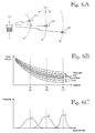
- the likelihood function p ( PAS a
- the objective is to model a probability distribution for the strength of the positioning-assisting signal when the locations of the target objects T01 and T02 are l and k , respectively.
- reference sign 61 denotes a location of target object T02
- reference signs 62A, 62B and 62C denote three different locations for target object T01, such that the respective distance from T02 is d 1 , d 2 and d 3 .
- Such modelling can be implemented in two phases.
- a first phase the base level and variance of the signal strength is estimated according to the distance between the target objects.
- Figure 6B shows a graphs of signal strength as a function of distance from target object T02
- Figure 6C shows the probability of an observation versus signal strength for the three T01 locations 62A, 62B and 62C.
- Figures 6A to 6C collectively show an example of a signal strength model wherein the expected signal strength level decreases and the expected signal variance increases as the distance between the target objects increases.
- FIG. 7A shows three locations denoted by reference signs, 72A, 72B and 72C. These locations are equidistant from the target object T02, but only location 72A has an unobstructed signal path from the location 71 of target object T02, while signal reception at location 72B is affected by wall W1 and at location 72C by walls W2 and W3.
- Figure 7B illustrates how the presence of walls W1 to W3 could affect the signal strength observed at locations 72A, 72B and 72C.
- estimation of p ( PAS a
- radio signals may reflect from walls or other obstacles causing multipath effects, which can significantly affect the observed signal strength level at some locations.
- the angle of the signal and the orientation of the target objects should be taken into account.
- Some embodiments may also model dynamic changes in the environment such as moving obstacles or changing transmission powers. It should be apparent to a person skilled in art that the exact nature of the methods used to model the positioning-assisting signal is not essential for this invention.
- the probability p ( PAS a
- FIG. 8 is a schematic block diagram of a signal transceiver.
- the signal transceiver STR comprises a central processing unit (CPU) 800, memory 802, input-output circuitry 804 which consists of input circuitry 806 and output circuitry 808.
- the signal transceiver STR further comprises reception/transmission circuitry 810 which comprises a transmission circuitry 812, reception circuitry 814 and antenna 816.
- reception circuitry 814 also comprises a received signal strength indicator RSSI.
- all elements 800 through 816 can be conventional as used in the relevant art.
- the signal transceiver STR used in implementations of the present invention comprises an observation generation unit 820 which is coupled with the above-described elements as follows.
- the observation generation unit 820 is typically implemented via program routines stored in the memory 802.
- the execution of the program routines of the observation generation directs the CPU 800 to obtain readings from the RSSI indicator in the reception circuitry 814.
- the execution also directs the CPU 800 to send the observations via the transmission circuitry 812 to the communication network which relays it to the positioning engine PE (see Figures 1 and 9 ).
- the observation generation unit 820 may process observations of some other radiometric quantity, such as bit error rate/ratio, timing advance or the like, or it may obtain the observations from other measurement circuitry which is operatively coupled to the input circuitry 806 and which, for example, is operable to measure an atmospheric, acoustic or optical quantity in the environment.
- some other radiometric quantity such as bit error rate/ratio, timing advance or the like
- FIG 9 schematically depicts a practical implementation of the invention.
- the first and second target objects T01, T02 are depicted as hands of persons carrying respective signal transceivers (signalling devices) STR1, STR2.
- the basic features of a representative signal transceiver STR was described in connection with Figure 8 .
- the signal transceivers STR1, STR2 are coupled to a communication network NW, such as a WLAN network, which comprises several base stations BS1, BS2, BS3, etc.
- NW such as a WLAN network
- the location-dependent physical quantity observed by both signal transceivers STR1, STR2 is signal strength from the base stations BS1 - BS3.
- the dual arrows between the signal transceivers STR1, STR2 and the base stations BS1 - BS3 indicate the fact that the observe strength from the base stations BS1 - BS3 and use at least one of the base stations to send the observations to the positioning engine, which in this example is a centralized positioning server.
- the location of the first and second target object respectively influence the first and second observation sets OS1, OS2, both of which are examples of quantity observation sets.
- the relation of location vs. signal strength from the base stations is modelled in a data model DM in the positioning engine PE.
- the data model DM may indicate a calibrated value for each of several locations in the environment.
- the data model DM is a probabilistic model which indicates a probability distribution for the signal strength (or other location-dependent physical quantities) for each of several locations, called sample points.
- a probability distribution provides more information than a single calibrated or expected value and is more robust in cases wherein the observations are ambiguous or contradictory.
- the first signal transceiver STR1 is a small positioning tag.
- the tag STR1 is designed to send observations only intermittently.
- the tag may be provided with an operation logic which puts the timer on sleep mode for most of the time and wakes up the tag in response to timer alerts or activity detections from a push button or motion sensor.
- the tag wakes up, it observes the signal strength or other location-dependent physical quantities and sends the observation(s) via the network NW to the positioning engine PE.
- the tag may also indicate the activity that triggered the sending of the observation. For instance, the person depicted as target object T01 can press the push button to indicate that some attention or assistance is needed. That may serve as an indication that the tag and the person carrying it should be located as soon as possible.
- the search of the tag STR1 is assisted by the second signal transceiver STR2 which is carried by another person depicted as target object T02.
- the second signal transceiver STR2 is depicted as a pocket computer smart phone, herein called a PDA (for "personal digital assistant").
- PDA for "personal digital assistant”
- a typical PDA has more processing power and a bigger battery, which is why it can make more frequent observations than the tag STR1 can.
- the typical PDA also has a display and/or loudspeaker/headphone, which is why it can receive current positioning data or explicit motion instructions from the positioning engine and relay such information to its user.
- Prior art positioning systems rely on modelling of at least one location-dependent physical quantity, such as signal strength, at several locations in the environment, called sample points.
- location-dependent physical quantity such as signal strength
- signal strength of transmissions by the base stations is a typical example of the location-dependent physical quantity
- the locations of the sample points must be known.
- Some positioning techniques may rely on physical quantities other than signal strength, but it is common to reference the observations of a mobile target object against a data model which is based on sample points with known locations.
- the present invention complements such prior art positioning systems by utilizing information which is based on observations from one or more positioning-assisting signals, one of which is denoted by reference sign PAS.
- the positioning-assisting signal PAS is sent by one signal transceiver, eg STR2, and received by another one, eg STR1.
- Neither the origin nor the destination of the positioning-assisting signal PAS is indicated by the data model or otherwise known a priori.
- the invention is partially based on the somewhat surprising discovery that although neither the origin nor the destination of the positioning-assisting signal is known a priori, an observation of the positioning-assisting signal nevertheless provides useful information which is not properly utilized in prior art positioning systems.
- the positioning engine PE may be operatively coupled to a signal propagation model PM which indicates a signal value probability distribution as a function of a distance travelled by the signal.
- the signal propagation model may also take into account obstacles between the signal's originating and terminating locations in the environment. This information can be used to derive the additional location probability distribution ALPD shown in Figure 4 .
- the additional location probability distribution in turn can be used to resolve ambiguities regarding either target object's location, by producing the updated location probability distribution LPD1, as described in connection with Figure 5 .
- the positioning engine PE may comprise or be coupled with a user interface Ul and or database DB. For instance, the positioning engine PE may output current location estimates, search statistics or the like on the display of the user interface Ul. Alternatively or additionally the positioning engine PE may store observations, locations estimates and/or motion histories in the database DB.
- the positioning engine may employ one or more tables which indicate various associations. As discussed in connection with Figure 1 , an association table AT links target objects to their associated and co-located transceivers. An optional device model table DMT associates signal transceivers with respective device models that compensate for the differences between different signalling devices' observations of signal quality parameters. The positioning engine or its operator may select among the multiple device models a specific device model for each specific signal transceiver. Device models are described in more detail in commonly-owned patent application WO2004/008796 . The techniques described in WO2004/008796 can be used to that compensate for the differences between different signalling devices' observations of the any of the observations OS1 to OS3.
- the positioning engine may also employ a motion model table MMT to indicate a motion model for each target object based on the target object's motion characteristics, as described in commonly-owned patent application EP 1 796 419 .
- the motion models may be used to further resolve ambiguities by excluding impossible or highly improbable locations and transitions.
- Ambiguities may be resolved further by employing a graph which models the topology of the environment by indicating several nodes which are permissible locations in the environment and several arcs which are permissible transitions between two nodes. Creation and using of graphs is described detail in commonly-owned patent application WO2004/008795 .
- the invention is also applicable to positioning tasks in an environment comprising two or more target objects wherein only a few or none of the target objects can be located with adequate accuracy using observations on the location-dependent quantities.
- an ad-hoc network wherein only a few base stations are placed on fixed positions and the network clients communicate with each other to establish a communication network is an illustrative example of a case wherein target-specific observations may not be sufficient for accurate positioning, as illustrated in Figure 10A.
- Figure 10A shows a scenario in which a network or network section has three base stations A, B and C, denoted by respective reference signs 101A, 101B and 101C.
- Figure 10A also shows three target objects TO2/1, TO2/2, and TO2/3, denoted by respective reference signs 102A, 102B and 102C each of which is able to observe only one of the base stations A, B and C.
- the base stations' radiation patterns are substantially circular, which is why any given observed signal value is equally probable in all directions around a base station.
- the location probability distributions (LPD2/1, LPD2/2, LPD2/3) for the target objects are also substantially circular, which means that the positioning engine cannot reliably the directions between each of the target object TO2/1, TO2/2, and TO2/3 from their respective base stations A, B and C.
- Figure 10A also shows a target object T01, denoted by reference numeral 103, which is located too far away from all base stations to observe any of them.
- Figure 10B shows how the present invention can be used to locate the target object T01 by using positioning-assisting signals PAS1, PAS2 and PAS3 transmitted by T01 and received by target objects TO2/1, TO2/2 and TO2/3, although no prior knowledge or quantity observations related to T01 is available.
- the target object T01 corresponds to the first target object having a location probability distribution LPD1
- any of target objects TO2/1, T02/2, or TO2/3 corresponds to the second target object T02 having a location probability distribution LPD2, denoted in Figure 10B as LPD2/1, LPD2/2 and LPD2/3.
- Reference signs PAS1, PAS2, or PAS3 correspond to the positioning assisting signal(s) PAS as observed by the target objects TO2/1, TO2/2 and TO2/3.
- the positioning engine can determine an updated first location probability distribution and estimate the location of T01 accurately by combining the additional location probability distributions.
- combining the distributions can be performed in three iteration steps. First, the positioning engine determines an updated first location probability distribution LPD1'/1 by combining ALPD/1 with the initial first location probability distribution LPD1 for the first target object wherein all locations are equally probable as nothing is known about the location of T01 in advance.
- the positioning engine uses LPD1'/1 in place of LPD1 when performing the next iteration and combines it with ALPD/2 to determine a further updated first location probability distribution LPD1'/2. Accordingly, in the third iteration, the positioning uses LPD1'/2 in place of LPD1 when combining it with ALPD/3 to determine the final updated first location probability distribution LPD'1/3 which is used to determine a location estimate for T01.
- Figure 11 shows another example comprising similar iterative steps as in the previous example.
- the scenario shown in Figure 11 comprises only two target objects, T01 and T02, but the positioning engine PE (see Figures 1 and 9 ) receives three positioning-assisting observation sets based on three positioning-assisting signals PAS1, PAS2 and PAS3 transmitted by the signalling devices associated with target object T01 at different times denoted by t1, t2 and t3.
- the example shown in Figure 11 is based on the assumption that the location of T02 can be estimated fairly accurately and that the time intervals t2-t1 and t3-t2 between the positioning-assisting signals PAS1, PAS2 and PAS3 is long enough for T02 to move to another location before receiving the next positioning-assisting signals PAS2 at time t2 and PAS3 at time t3.
- the final updated first location probability distribution reflects the true location of T01 very accurately.
- the intersection (" ⁇ ") operator is shown as the operator being used to combine the additional location probability distributions ALPD1, ALPD2 and ALPD3 but other operators can be used, depending on the type of distribution (discrete or continuous, for example).
- the positioning engine may send movement instructions to the second target object(s), guiding it/them to move to a location which helps find the first target object.
- the instructions may be based on the received positioning-assisting observation sets, the current location probability distributions for the target objects, or both.
- the positioning engine controls a systematic search involving multiple target objects, wherein the positioning engine maintains a search map indicating the areas already visited by one or more target objects and the moving instructions point to a location not yet visited by any of the target objects.
- the movement of T02 in Figure 11 may have been instructed by the positioning engine.
- the positioning engine can reduce the number of possible locations for T01 and guide T02 to move to a location on which the next received positioning-assisting signal is expected to reduce the number of possible locations even further.
- the positioning engine can guide T02 to move directly towards the estimated location of TO1 to actually find it.
- the inventive concept can be implemented in various ways. For instance, some of the examples described above used the convention that the first transceiver associated and oo-located with the first target object is a low-cost positioning tag, while the second transceiver associated and co-located with the second target object is a general-purpose device with better observation capabilities, but the invention is not restricted to this setup, and the first and second transceiver can have equal observation capabilities.
- a key feature of the invention is the fact that at least one signalling device co-located with a target object sends one or more positioning-assisting signals which are received by other signalling device(s).
- the maximum achievable positioning accuracy is limited by the set of observable location-dependent physical quantities within the positioning environment, because the location of a target object is estimated independently from other target objects using only quantity observations related to the target object.
- the information available to the positioning engine increases proportionally to the number of target objects in the environment because every mutual observation between the target objects efficiently reduces the uncertainty concerning the locations of the target objects.
- the use of the positioning-assisting signals sent by the mobile signalling devices and received by other mobile signalling devices provides additional information that does not exist in prior art positioning techniques.
Claims (10)
- Verfahren zum Bestimmen einer Positionsabschätzung für ein erstes Zielobjekt (TO1) in einer Umgebung, die ebenfalls ein zweites Zielobjekt (T02) umfasst,
wobei das Verfahren Folgendes umfasst:- das Unterhalten einer Positionierungsmaschine (PE), die funktionsfähig ist, um wenigstens eine positionsabhängige physikalische Größe mit einem Datenmodell (DM) der Umgebung zu modellieren, wobei die wenigstens eine positionsabhängige physikalische Größe durch die Position des zweiten Zielobjekts (T02) beeinflusst wird und wobei die Positionierungsmaschine funktionsfähig ist, um Positionswahrscheinlichkeitsverteilungen für das erste und das zweite Zielobjekt zu bestimmen,- das Verknüpfen des ersten und des zweiten Zielobjekts (TO1, T02) jeweils mit einer an gleicher Position befindlichen ersten beziehungsweise zweiten Signalisierungseinrichtung (STR1, STR2), wobei wenigstens die zweite Signalisierungseinrichtung (STR2) Mittel zum Senden eines Positionierungsunterstützungssignals umfasst und die erste Signalisierungseinrichtung (STR1) Mittel zum Empfangen des Positionierungsunterstützungssignals und Mittel zum Vornehmen von Beobachtungen zu der wenigstens einen positionsabhängigen physikalischen Größe aus dem Positionierungsunterstützungssignal umfasst,- das Empfangen von Beobachtungen zu der wenigstens einen positionsabhängigen physikalischen Größe durch die Positionierungsmaschine (PE),- das Senden eines Positionierungsunterstützungssignals (PAS1, PAS2) durch die zweite Signalisierungseinrichtung (STR2), wobei das Positionierungsunterstützungssignal durch die erste Signalisierungseinrichtung (STR1), die einen Positionierungsunterstützungsbeobachtungssatz zu der wenigstens einen positionsabhängigen physikalischen Größe daraus macht und den Positionierungsunterstützungsbeobachtungssatz an die Positionierungsmaschine (PE) sendet, empfangen wird, wobei die wenigstens eine der Signalisierungseinrichtungen und die andere Signalisierungseinrichtung mit unterschiedlichen Zielobjekten verknüpft und an gleicher Position befindlich sind,- das Herstellen eines Größenbeobachtungssatzes auf der Grundlage der empfangenen Beobachtungen zu der wenigstens einen positionsabhängigen physikalischen Größe durch die Positionierungsmaschine (PE),- das Bestimmen einer jeweiligen ersten beziehungsweise zweiten Positionswahrscheinlichkeitsverteilung (LPD1, LPD2) für das erste und das zweite Zielobjekt (TO1, TO2) durch die Positionierungsmaschine (PE), wobei wenigstens die zweite Positionswahrscheinlichkeitsverteilung auf dem Datenmodell (DM) und dem Größenbeobachtungssatz beruht,- das Bestimmen einer aktualisierten ersten Positionswahrscheinlichkeitsverteilung (ALPD1') auf der Grundlage der ersten Positionswahrscheinlichkeitsverteilung (LPD1), der zweiten Positionswahrscheinlichkeitsverteilung (LPD2) und des Positionierungsunterstützungsbeobachtungssatzes zu der wenigstens einen positionsabhängigen physikalischen Größe durch die Positionierungsmaschine (PE),- das Bestimmen der Positionsabschätzung für das erste Zielobjekt (TO1) auf der Grundlage der aktualisierten ersten Positionswahrscheinlichkeitsverteilung (LPD1') durch die Positionierungsmaschine (PE),- das Auslösen einer physikalischen Handlung auf der Grundlage der Positionsabschätzung für das erste Zielobjekt (TO1) durch die Positionierungsmaschine (PE),- dadurch gekennzeichnet, dass:- das Positionsunterstützungssignal als eine Reaktion auf ein vorhergehendes durch die erste Signalisierungseinrichtung gesendetes Positionsunterstützungssignal gesendet wird,- ein Steuergerät eine Operationslogik für das Senden des vorhergehenden Positionsunterstützungssignals definiert und das vorhergehende Positionsunterstützungssignal als Reaktion auf eine Sendeaufforderung von dem Steuergerät gesendet wird und- das Steuergerät die Operationslogik auf der Grundlage des Positionierungsunterstützungsbeobachtungssatzes einstellt, wobei das Einstellen der Operationslogik das Einstellen eines Zeitintervalls zwischen aufeinanderfolgenden Sendeaufforderungen umfasst. - Verfahren nach Anspruch 1, wobei die physikalische Handlung das Ausgeben der Positionsabschätzung für das erste Zielobjekt (TO1) an ein physikalisches Ausgabegerät und/oder einen physikalischen Speicher umfasst.
- Verfahren nach Anspruch 1 oder 2, wobei die zweite Signalisierungseinrichtung auf das vorhergehende Positionierungsunterstützungssignal durch das Senden des Positionierungssignals nur dann, wenn es eine angezeigte Notwendigkeit gibt, die Positionierung des ersten Zielobjekts zu unterstützen, reagiert.
- Verfahren nach einem der vorhergehenden Ansprüche, wobei das Datenmodell ein probabilistisches Datenmodell ist, das eine Wahrscheinlichkeitsverteilung für die wenigstens eine positionsabhängige physikalische Größe für jede von verschiedenen Positionen in der Umgebung angibt, und wobei der Schritt des Bestimmens der Positionswahrscheinlichkeitsverteilung (LPD1, LPD2) für ein Zielobjekt (TO1, T02) Folgendes umfasst:- die Positionierungsmaschine (PE) bestimmt eine Wahrscheinlichkeit für eine Beobachtung der wenigstens einen positionsabhängigen physikalischen Größe an einer hypothetischen Position des Zielobjekts, auf der Grundlage der Wahrscheinlichkeitsverteilung für die wenigstens eine positionsabhängige physikalische Größe, die durch das Datenmodell an der hypothetischen Position des Zielobjekts angegeben wird, und- die Positionierungsmaschine (PE) bestimmt eine Dichte der Positionswahrscheinlichkeitsverteilung an der hypothetischen Position des Zielobjekts auf der Grundlage der Wahrscheinlichkeit für die Beobachtung der wenigstens einen positionsabhängigen physikalischen Größe an der hypothetischen Position des Zielobjekts.
- Verfahren nach Anspruch 4, wobei der Schritt des Abschätzens der aktualisierten ersten Positionswahrscheinlichkeitsverteilung (LPD1') Folgendes umfasst:- das Abschätzen einer zusätzlichen Positionswahrscheinlichkeitsverteilung (ALPD) für das erste Zielobjekt (TO1) auf der Grundlage der zweiten Positionswahrscheinlichkeitsverteilung (LPD2) und des Positionierungsunterstützungsbeobachtungssatzes,- das Abschätzen der aktualisierten ersten Positionswahrscheinlichkeitsverteilung (LPD1') durch das Kombinieren der ersten Positionswahrscheinlichkeitsverteilung und der zusätzlichen Positionswahrscheinlichkeitsverteilung (ALPD).
- Verfahren nach Anspruch 5, wobei der Schritt des Abschätzens der zusätzlichen Positionswahrscheinlichkeitsverteilung (ALPD) das Verwenden eines Signalausbreitungsmodells (SPM) umfasst, wobei das Signalausbreitungsmodell funktionsfähig ist, um die Wahrscheinlichkeit des Positionierungsunterstützungsbeobachtungssatzes für hypothetische Positionen der Zielobjekte abzuschätzen.
- Verfahren nach Anspruch 6, wobei das Signalausbreitungsmodell (SPM) das Berücksichtigen von Hindernissen innerhalb der Umgebung, die das Positionierungsunterstützungssignal beeinträchtigen, umfasst.
- Verfahren nach einem der vorhergehenden Ansprüche, wobei die Positionierungsmaschine (PE) eine Positionsabschätzung für ein oder mehrere zweite Zielobjekte (T02) und den Fortschritt des Positionierungsunterstützungsbeobachtungssatzes in Abhängigkeit von der Positionsabschätzung für das eine oder die mehreren zweiten Zielobjekte überwacht und wobei die Positionierungsmaschine (PE) ferner dem einen oder den mehreren zweiten Zielobjekten (T02) Befehle zum Verändern der Position auf der Grundlage des Fortschritts des Positionierungsunterstützungsbeobachtungssatzes sendet.
- Positionierungsmaschine (PE) zum Bestimmen einer Positionsabschätzung für ein erstes Zielobjekt (TO1) in einer Umgebung, die ebenfalls ein zweites Zielobjekt (T02) umfasst und wobei wenigstens eine positionsabhängige physikalische Größe durch die Position des zweiten Zielobjekts beeinflusst wird,
wobei die Positionierungsmaschine Folgendes umfasst:- ein Datenmodell (DM), das die wenigstens eine positionsabhängige physikalische Größe der Umgebung modelliert,- Mittel zum Empfangen von Beobachtungen zu der wenigstens einen positionsabhängigen physikalischen Größe und- Mittel zum Bestimmen von Positionswahrscheinlichkeitsverteilungen für das erste und das zweite Zielobjekt,- Mittel (AT) zum Verknüpfen des ersten und des zweiten Zielobjekts (TO1, TO2) jeweils mit einer an gleicher Position befindlichen ersten beziehungsweise zweiten Signalisierungseinrichtung (STR1, STR2),- Mittel zum Empfangen von Beobachtungen zu der wenigstens einen positionsabhängigen physikalischen Größe, welche die Position des zweiten Zielobjekts (T02) widerspiegeln,- Mittel zum Empfangen eines Positionierungsunterstützungsbeobachtungssatzes, hergestellt aus einem Positionierungsunterstützungssignal, das durch wenigstens eine der Signalisierungseinrichtungen gesendet und durch eine andere der Signalisierungseinrichtungen empfangen wird, wobei die wenigstens eine der Signalisierungseinrichtungen und die andere Signalisierungseinrichtung mit unterschiedlichen Zielobjekten verknüpft und an gleicher Position befindlich sind,- Mittel zum Herstellen eines Größenbeobachtungssatzes auf der Grundlage der empfangenen Beobachtungen zu der wenigstens einen positionsabhängigen physikalischen Größe,- Mittel zum Bestimmen einer jeweiligen ersten beziehungsweise zweiten Positionswahrscheinlichkeitsverteilung (LPD1, LPD2) für das erste und das zweite Zielobjekt (TO1, TO2), wobei wenigstens die zweite Positionswahrscheinlichkeitsverteilung auf dem Datenmodell (DM) und dem Größenbeobachtungssatz beruht,- Mittel zum Bestimmen einer aktualisierten ersten Positionswahrscheinlichkeitsverteilung (LPD1') auf der Grundlage der ersten Positionswahrscheinlichkeitsverteilung (LPD1), der zweiten Positionswahrscheinlichkeitsverteilung (LPD2) und des Positionierungsunterstützungsbeobachtungssatzes,- Mittel zum Bestimmen der Positionsabschätzung für das erste Zielobjekt (TO1) auf der Grundlage der aktualisierten ersten Positionswahrscheinlichkeitsverteilung (LPD1'),- Mittel zum Auslösen einer physikalischen Handlung auf der Grundlage der Positionsabschätzung für das erste Zielobjekt (TO1)- dadurch gekennzeichnet, dass die Positionierungsmaschine ferner ein Steuergerät umfasst, wobei:- das Positionsunterstützungssignal als eine Reaktion auf ein vorhergehendes durch die erste Signalisierungseinrichtung gesendetes Positionsunterstützungssignal gesendet wird,- das Steuergerät dafür konfiguriert ist, eine Operationslogik für das Senden des vorhergehenden Positionsunterstützungssignals zu definieren und das vorhergehende Positionsunterstützungssignal als Reaktion auf eine Sendeaufforderung von dem Steuergerät gesendet wird und- das Steuergerät dafür konfiguriert ist, die Operationslogik auf der Grundlage des Positionierungsunterstützungsbeobachtungssatzes einzustellen, wobei das Einstellen der Operationslogik das Einstellen eines Zeitintervalls zwischen aufeinanderfolgenden Sendeaufforderungen umfasst. - Rechnerprogrammerzeugnis für ein Datenverarbeitungssystem, wobei eine Ausführung des Rechnerprogrammerzeugnisses in dem Datenverarbeitungssystem veranlasst, dass das Datenverarbeitungssystem die Positionierungsmaschine nach Anspruch 9 umsetzt.
Applications Claiming Priority (1)
| Application Number | Priority Date | Filing Date | Title |
|---|---|---|---|
| PCT/FI2008/050159 WO2009122000A1 (en) | 2008-04-02 | 2008-04-02 | Positioning of mobile objects based on mutually transmitted signals |
Publications (3)
| Publication Number | Publication Date |
|---|---|
| EP2263098A1 EP2263098A1 (de) | 2010-12-22 |
| EP2263098A4 EP2263098A4 (de) | 2011-11-09 |
| EP2263098B1 true EP2263098B1 (de) | 2015-01-07 |
Family
ID=41134871
Family Applications (1)
| Application Number | Title | Priority Date | Filing Date |
|---|---|---|---|
| EP08736808.0A Active EP2263098B1 (de) | 2008-04-02 | 2008-04-02 | Positionsbestimmung von mobilen objekten auf der basis von gegenseitig gesendeten signalen |
Country Status (3)
| Country | Link |
|---|---|
| US (1) | US8456364B2 (de) |
| EP (1) | EP2263098B1 (de) |
| WO (1) | WO2009122000A1 (de) |
Families Citing this family (39)
| Publication number | Priority date | Publication date | Assignee | Title |
|---|---|---|---|---|
| US20070231192A1 (en) * | 2006-03-31 | 2007-10-04 | Searete Llc, A Limited Liability Corporation Of The State Of Delaware | Sterilization methods and systems |
| US8114342B2 (en) * | 2006-03-31 | 2012-02-14 | The Invention Science Fund I, Llc | Methods and systems for monitoring sterilization status |
| US11185604B2 (en) | 2006-03-31 | 2021-11-30 | Deep Science Llc | Methods and systems for monitoring sterilization status |
| US8758679B2 (en) * | 2006-03-31 | 2014-06-24 | The Invention Science Fund I, Llc | Surveying sterilizer methods and systems |
| US8932535B2 (en) * | 2006-03-31 | 2015-01-13 | The Invention Science Fund I, Llc | Surveying sterilizer methods and systems |
| US8277724B2 (en) * | 2006-03-31 | 2012-10-02 | The Invention Science Fund I, Llc | Sterilization methods and systems |
| US20070254015A1 (en) * | 2006-04-28 | 2007-11-01 | Searete Llc, A Limited Liability Corporation Of The State Of Delaware | Sanitizing surfaces |
| US9740921B2 (en) | 2009-02-26 | 2017-08-22 | Tko Enterprises, Inc. | Image processing sensor systems |
| US9293017B2 (en) * | 2009-02-26 | 2016-03-22 | Tko Enterprises, Inc. | Image processing sensor systems |
| US9277878B2 (en) * | 2009-02-26 | 2016-03-08 | Tko Enterprises, Inc. | Image processing sensor systems |
| GB2481191A (en) | 2010-02-25 | 2011-12-21 | Sita Information Networking Computing Ireland Ltd | Graphical development tool for software application development |
| JP5712521B2 (ja) * | 2010-07-27 | 2015-05-07 | 富士通株式会社 | 測位装置、測位信号送信装置、測位方法、および測位信号送信方法 |
| US8504077B2 (en) * | 2010-12-04 | 2013-08-06 | Wavemarket, Inc. | System and method for monitoring and disseminating mobile device location information |
| AU2011347893A1 (en) | 2010-12-21 | 2013-05-23 | Sita N.V | Reservation system and method |
| EP2492707B1 (de) * | 2011-02-28 | 2016-06-08 | Mitsubishi Electric R&D Centre Europe B.V. | Verfahren zur Bestimmung einer Karte auf einem mit einer Basisstation verknüpften Bereich |
| RU2589315C2 (ru) | 2011-08-03 | 2016-07-10 | СИТА ИНФОРМЕЙШН НЕТВОРКИНГ КОМПЬЮТИНГ ЮЭсЭй, ИНК | Система обработки и отслеживания предметов и способ для этого |
| GB2499288A (en) * | 2012-02-09 | 2013-08-14 | Sita Inf Networking Computing Usa Inc | Path determination |
| US9087204B2 (en) | 2012-04-10 | 2015-07-21 | Sita Information Networking Computing Ireland Limited | Airport security check system and method therefor |
| US20140111380A1 (en) * | 2012-10-22 | 2014-04-24 | Cambridge Silicon Radio Limited | Method for short-range proximity derivation and tracking |
| US10397732B2 (en) | 2013-03-14 | 2019-08-27 | Airista Flow, Inc. | Positioning tag with alert function |
| US10320908B2 (en) | 2013-03-25 | 2019-06-11 | Sita Information Networking Computing Ireland Limited | In-flight computing device for aircraft cabin crew |
| GB2515142B (en) | 2013-06-14 | 2020-12-16 | Sita Information Networking Computing Ireland Ltd | Portable user control system and method therefor |
| GB2517691A (en) | 2013-08-26 | 2015-03-04 | Univ Dublin City | Location detection system and method |
| GB2523441A (en) | 2014-02-19 | 2015-08-26 | Sita Information Networking Computing Ireland Ltd | Reservation system and method therefor |
| TWI540917B (zh) * | 2014-07-16 | 2016-07-01 | 緯創資通股份有限公司 | 建立裝置間直接連線的方法以及使用該方法的系統 |
| US10049556B2 (en) * | 2014-09-30 | 2018-08-14 | Xiaomi Inc. | Method and device for positioning objects |
| CN104299016B (zh) * | 2014-09-30 | 2018-02-02 | 小米科技有限责任公司 | 对象定位方法及装置 |
| US10001546B2 (en) | 2014-12-02 | 2018-06-19 | Sita Information Networking Computing Uk Limited | Apparatus for monitoring aircraft position |
| US9734682B2 (en) | 2015-03-02 | 2017-08-15 | Enovate Medical, Llc | Asset management using an asset tag device |
| US9967803B2 (en) | 2015-04-30 | 2018-05-08 | Mist Systems, Inc. | Dynamic virtual beacon methods and apparatus |
| US9363784B1 (en) | 2015-04-30 | 2016-06-07 | Mist Systems Inc. | Methods and apparatus relating to the use of real and/or virtual beacons |
| US9743254B2 (en) * | 2015-04-30 | 2017-08-22 | Mist Systems, Inc. | Methods and apparatus relating to the use of received signals to determine wireless terminal location and/or refine location determination models |
| US10219166B2 (en) | 2015-04-30 | 2019-02-26 | Mist Systems, Inc. | Methods and apparatus for generating, transmitting and/or using beacons |
| US10025961B2 (en) * | 2015-07-27 | 2018-07-17 | Symbol Technologies, Llc | Arrangement for, and method of, enhancing accuracy of data collection for items located in a venue |
| TWI594643B (zh) * | 2016-07-01 | 2017-08-01 | 晶睿通訊股份有限公司 | 無線收發系統、無線接收裝置及無線收發方法 |
| US10371787B2 (en) * | 2017-01-13 | 2019-08-06 | Raytheon Company | Emitter geolocation using sorted observations |
| WO2019116786A1 (ja) * | 2017-12-15 | 2019-06-20 | 株式会社村田製作所 | 無線通信装置、位置検知システム、無線通信方法、および位置検知データ通信方法 |
| CN112272778A (zh) * | 2018-06-13 | 2021-01-26 | 三菱电机株式会社 | 轨迹推测装置以及便携信息终端 |
| MY195505A (en) * | 2018-12-31 | 2023-01-27 | Mimos Berhad | System And Method For Estimating Geospatial Position By Composing Positioning Scheme |
Family Cites Families (12)
| Publication number | Priority date | Publication date | Assignee | Title |
|---|---|---|---|---|
| US5689269A (en) * | 1995-01-25 | 1997-11-18 | American Technology Corporation | GPS relative position detection system |
| US7257414B2 (en) * | 1998-09-22 | 2007-08-14 | Polaris Wireless, Inc. | Estimating the Location of a Wireless Terminal Based on Non-Uniform Probabilities of Movement |
| US6839560B1 (en) * | 1999-02-25 | 2005-01-04 | Microsoft Corporation | Using a derived table of signal strength data to locate and track a user in a wireless network |
| FI111901B (fi) | 2000-12-29 | 2003-09-30 | Ekahau Oy | Sijainnin arviointi langattomissa tietoliikenneverkoissa |
| US6970097B2 (en) * | 2001-05-10 | 2005-11-29 | Ge Medical Systems Information Technologies, Inc. | Location system using retransmission of identifying information |
| FI113410B (fi) * | 2002-05-31 | 2004-04-15 | Ekahau Oy | Probabilistinen malli paikannustekniikkaa varten |
| FI113330B (fi) | 2002-07-10 | 2004-03-31 | Ekahau Oy | Signaalilaatumittausten sovelluksia |
| US7592909B2 (en) | 2006-01-19 | 2009-09-22 | Board Of Regents, The University Of Texas System | Location and tracking system using wireless technology |
| US7312752B2 (en) * | 2003-10-22 | 2007-12-25 | Awarepoint Corporation | Wireless position location and tracking system |
| US7359718B2 (en) * | 2004-04-30 | 2008-04-15 | Hong Kong Applied Science And Technology Research Institute Co., Ltd. | Location determination and location tracking in wireless networks |
| US7904097B2 (en) * | 2005-12-07 | 2011-03-08 | Ekahau Oy | Location determination techniques |
| US20070296633A1 (en) * | 2006-04-11 | 2007-12-27 | Oki Electric Industry Co., Ltd. | System and method for position estimation with high accuracy and a wireless communication terminal device therefor |
-
2008
- 2008-04-02 EP EP08736808.0A patent/EP2263098B1/de active Active
- 2008-04-02 WO PCT/FI2008/050159 patent/WO2009122000A1/en active Application Filing
- 2008-04-02 US US12/933,544 patent/US8456364B2/en active Active
Also Published As
| Publication number | Publication date |
|---|---|
| WO2009122000A1 (en) | 2009-10-08 |
| EP2263098A1 (de) | 2010-12-22 |
| US20110018769A1 (en) | 2011-01-27 |
| US8456364B2 (en) | 2013-06-04 |
| EP2263098A4 (de) | 2011-11-09 |
Similar Documents
| Publication | Publication Date | Title |
|---|---|---|
| EP2263098B1 (de) | Positionsbestimmung von mobilen objekten auf der basis von gegenseitig gesendeten signalen | |
| Papapostolou et al. | RFID-assisted indoor localization and the impact of interference on its performance | |
| KR100671283B1 (ko) | 순차 송수신 방식을 이용한 비동기 무선 측위 시스템 및방법 | |
| JP5015423B2 (ja) | ビーコン装置を用いて位置決定を行うターゲット装置、遠隔サーバ及び方法 | |
| JP5951492B2 (ja) | 無線ネットワークでの位置検出 | |
| Ni et al. | LANDMARC: Indoor location sensing using active RFID | |
| Wang et al. | Toward robust indoor localization based on Bayesian filter using chirp-spread-spectrum ranging | |
| Rodriguez et al. | In-building location using bluetooth | |
| GB2518926A (en) | Determination of proximity using a plurality of transponders | |
| US20230368641A1 (en) | Processing alert signals from positioning devices | |
| Tauber | Indoor location systems for pervasive computing | |
| Lee et al. | A location tracking system using ble beacon exploiting a double-gaussian filter | |
| Cinefra | An adaptive indoor positioning system based on Bluetooth Low Energy RSSI | |
| Sulaiman et al. | Radio map generation approaches for an RSSI-based indoor positioning system | |
| KR101333111B1 (ko) | 위치 추정 시스템 및 방법 | |
| Jamâa et al. | Easyloc: Plug-and-play RSS-based localization in wireless sensor networks | |
| Lee et al. | IEEE 802.15. 4a CSS-based mobile object locating system using sequential Monte Carlo method | |
| Chen et al. | A Review of Device-Free Indoor Positioning for Home-Based Care of the Aged: Techniques and Technologies. | |
| Danebjer et al. | A hybrid approach to GPS-free geolocation over LoRa | |
| Ghadami | Localization in a wireless sensor network with a geometric approach of Trilateration and mathematical modeling of sine and cosine functions | |
| Sonawane et al. | Improve Performance Wireless Sensor Network Localization using RSSI and AEMM | |
| Dias | Enhancing Indoor Localisation: a Bluetooth Low Energy (BLE) Beacon Placement approach | |
| Biswas et al. | Reliable positioning-based human activity recognition based on indoor RSSI changes | |
| EP4315295A1 (de) | Näherungsmessverfahren und -vorrichtung | |
| Dardari et al. | Cooperative localization in wireless ad hoc and sensor networks |
Legal Events
| Date | Code | Title | Description |
|---|---|---|---|
| PUAI | Public reference made under article 153(3) epc to a published international application that has entered the european phase |
Free format text: ORIGINAL CODE: 0009012 |
|
| 17P | Request for examination filed |
Effective date: 20101008 |
|
| AK | Designated contracting states |
Kind code of ref document: A1 Designated state(s): AT BE BG CH CY CZ DE DK EE ES FI FR GB GR HR HU IE IS IT LI LT LU LV MC MT NL NO PL PT RO SE SI SK TR |
|
| AX | Request for extension of the european patent |
Extension state: AL BA MK RS |
|
| DAX | Request for extension of the european patent (deleted) | ||
| A4 | Supplementary search report drawn up and despatched |
Effective date: 20111007 |
|
| RIC1 | Information provided on ipc code assigned before grant |
Ipc: G01S 5/18 20060101ALI20110930BHEP Ipc: G01S 5/00 20060101ALI20110930BHEP Ipc: G01S 5/16 20060101ALI20110930BHEP Ipc: G01S 5/02 20100101AFI20110930BHEP |
|
| 17Q | First examination report despatched |
Effective date: 20120601 |
|
| 111Z | Information provided on other rights and legal means of execution |
Free format text: AT BE BG CH CY CZ DE DK EE ES FI FR GB GR HR HU IE IS IT LT LU LV MC MT NL NO PL PT RO SE SI SK TR Effective date: 20131001 |
|
| GRAP | Despatch of communication of intention to grant a patent |
Free format text: ORIGINAL CODE: EPIDOSNIGR1 |
|
| INTG | Intention to grant announced |
Effective date: 20140723 |
|
| GRAS | Grant fee paid |
Free format text: ORIGINAL CODE: EPIDOSNIGR3 |
|
| GRAA | (expected) grant |
Free format text: ORIGINAL CODE: 0009210 |
|
| RAP1 | Party data changed (applicant data changed or rights of an application transferred) |
Owner name: EKAHAU OY |
|
| AK | Designated contracting states |
Kind code of ref document: B1 Designated state(s): AT BE BG CH CY CZ DE DK EE ES FI FR GB GR HR HU IE IS IT LI LT LU LV MC MT NL NO PL PT RO SE SI SK TR |
|
| REG | Reference to a national code |
Ref country code: GB Ref legal event code: FG4D |
|
| REG | Reference to a national code |
Ref country code: CH Ref legal event code: EP |
|
| REG | Reference to a national code |
Ref country code: IE Ref legal event code: FG4D |
|
| REG | Reference to a national code |
Ref country code: AT Ref legal event code: REF Ref document number: 706096 Country of ref document: AT Kind code of ref document: T Effective date: 20150215 |
|
| REG | Reference to a national code |
Ref country code: DE Ref legal event code: R096 Ref document number: 602008036231 Country of ref document: DE Effective date: 20150226 |
|
| REG | Reference to a national code |
Ref country code: NL Ref legal event code: VDEP Effective date: 20150107 |
|
| REG | Reference to a national code |
Ref country code: AT Ref legal event code: MK05 Ref document number: 706096 Country of ref document: AT Kind code of ref document: T Effective date: 20150107 |
|
| REG | Reference to a national code |
Ref country code: LT Ref legal event code: MG4D |
|
| PG25 | Lapsed in a contracting state [announced via postgrant information from national office to epo] |
Ref country code: LT Free format text: LAPSE BECAUSE OF FAILURE TO SUBMIT A TRANSLATION OF THE DESCRIPTION OR TO PAY THE FEE WITHIN THE PRESCRIBED TIME-LIMIT Effective date: 20150107 Ref country code: FI Free format text: LAPSE BECAUSE OF FAILURE TO SUBMIT A TRANSLATION OF THE DESCRIPTION OR TO PAY THE FEE WITHIN THE PRESCRIBED TIME-LIMIT Effective date: 20150107 Ref country code: ES Free format text: LAPSE BECAUSE OF FAILURE TO SUBMIT A TRANSLATION OF THE DESCRIPTION OR TO PAY THE FEE WITHIN THE PRESCRIBED TIME-LIMIT Effective date: 20150107 Ref country code: BG Free format text: LAPSE BECAUSE OF FAILURE TO SUBMIT A TRANSLATION OF THE DESCRIPTION OR TO PAY THE FEE WITHIN THE PRESCRIBED TIME-LIMIT Effective date: 20150407 Ref country code: NO Free format text: LAPSE BECAUSE OF FAILURE TO SUBMIT A TRANSLATION OF THE DESCRIPTION OR TO PAY THE FEE WITHIN THE PRESCRIBED TIME-LIMIT Effective date: 20150407 Ref country code: HR Free format text: LAPSE BECAUSE OF FAILURE TO SUBMIT A TRANSLATION OF THE DESCRIPTION OR TO PAY THE FEE WITHIN THE PRESCRIBED TIME-LIMIT Effective date: 20150107 Ref country code: SE Free format text: LAPSE BECAUSE OF FAILURE TO SUBMIT A TRANSLATION OF THE DESCRIPTION OR TO PAY THE FEE WITHIN THE PRESCRIBED TIME-LIMIT Effective date: 20150107 |
|
| PG25 | Lapsed in a contracting state [announced via postgrant information from national office to epo] |
Ref country code: IS Free format text: LAPSE BECAUSE OF FAILURE TO SUBMIT A TRANSLATION OF THE DESCRIPTION OR TO PAY THE FEE WITHIN THE PRESCRIBED TIME-LIMIT Effective date: 20150507 Ref country code: AT Free format text: LAPSE BECAUSE OF FAILURE TO SUBMIT A TRANSLATION OF THE DESCRIPTION OR TO PAY THE FEE WITHIN THE PRESCRIBED TIME-LIMIT Effective date: 20150107 Ref country code: GR Free format text: LAPSE BECAUSE OF FAILURE TO SUBMIT A TRANSLATION OF THE DESCRIPTION OR TO PAY THE FEE WITHIN THE PRESCRIBED TIME-LIMIT Effective date: 20150408 Ref country code: LV Free format text: LAPSE BECAUSE OF FAILURE TO SUBMIT A TRANSLATION OF THE DESCRIPTION OR TO PAY THE FEE WITHIN THE PRESCRIBED TIME-LIMIT Effective date: 20150107 Ref country code: NL Free format text: LAPSE BECAUSE OF FAILURE TO SUBMIT A TRANSLATION OF THE DESCRIPTION OR TO PAY THE FEE WITHIN THE PRESCRIBED TIME-LIMIT Effective date: 20150107 Ref country code: PL Free format text: LAPSE BECAUSE OF FAILURE TO SUBMIT A TRANSLATION OF THE DESCRIPTION OR TO PAY THE FEE WITHIN THE PRESCRIBED TIME-LIMIT Effective date: 20150107 |
|
| REG | Reference to a national code |
Ref country code: DE Ref legal event code: R097 Ref document number: 602008036231 Country of ref document: DE |
|
| PG25 | Lapsed in a contracting state [announced via postgrant information from national office to epo] |
Ref country code: DK Free format text: LAPSE BECAUSE OF FAILURE TO SUBMIT A TRANSLATION OF THE DESCRIPTION OR TO PAY THE FEE WITHIN THE PRESCRIBED TIME-LIMIT Effective date: 20150107 Ref country code: CZ Free format text: LAPSE BECAUSE OF FAILURE TO SUBMIT A TRANSLATION OF THE DESCRIPTION OR TO PAY THE FEE WITHIN THE PRESCRIBED TIME-LIMIT Effective date: 20150107 Ref country code: RO Free format text: LAPSE BECAUSE OF FAILURE TO SUBMIT A TRANSLATION OF THE DESCRIPTION OR TO PAY THE FEE WITHIN THE PRESCRIBED TIME-LIMIT Effective date: 20150107 Ref country code: EE Free format text: LAPSE BECAUSE OF FAILURE TO SUBMIT A TRANSLATION OF THE DESCRIPTION OR TO PAY THE FEE WITHIN THE PRESCRIBED TIME-LIMIT Effective date: 20150107 Ref country code: SK Free format text: LAPSE BECAUSE OF FAILURE TO SUBMIT A TRANSLATION OF THE DESCRIPTION OR TO PAY THE FEE WITHIN THE PRESCRIBED TIME-LIMIT Effective date: 20150107 |
|
| PLBE | No opposition filed within time limit |
Free format text: ORIGINAL CODE: 0009261 |
|
| STAA | Information on the status of an ep patent application or granted ep patent |
Free format text: STATUS: NO OPPOSITION FILED WITHIN TIME LIMIT |
|
| PG25 | Lapsed in a contracting state [announced via postgrant information from national office to epo] |
Ref country code: MC Free format text: LAPSE BECAUSE OF FAILURE TO SUBMIT A TRANSLATION OF THE DESCRIPTION OR TO PAY THE FEE WITHIN THE PRESCRIBED TIME-LIMIT Effective date: 20150107 Ref country code: LU Free format text: LAPSE BECAUSE OF FAILURE TO SUBMIT A TRANSLATION OF THE DESCRIPTION OR TO PAY THE FEE WITHIN THE PRESCRIBED TIME-LIMIT Effective date: 20150402 |
|
| REG | Reference to a national code |
Ref country code: CH Ref legal event code: PL |
|
| 26N | No opposition filed |
Effective date: 20151008 |
|
| PG25 | Lapsed in a contracting state [announced via postgrant information from national office to epo] |
Ref country code: IT Free format text: LAPSE BECAUSE OF FAILURE TO SUBMIT A TRANSLATION OF THE DESCRIPTION OR TO PAY THE FEE WITHIN THE PRESCRIBED TIME-LIMIT Effective date: 20150107 |
|
| REG | Reference to a national code |
Ref country code: IE Ref legal event code: MM4A |
|
| PG25 | Lapsed in a contracting state [announced via postgrant information from national office to epo] |
Ref country code: CH Free format text: LAPSE BECAUSE OF NON-PAYMENT OF DUE FEES Effective date: 20150430 Ref country code: LI Free format text: LAPSE BECAUSE OF NON-PAYMENT OF DUE FEES Effective date: 20150430 |
|
| PG25 | Lapsed in a contracting state [announced via postgrant information from national office to epo] |
Ref country code: SI Free format text: LAPSE BECAUSE OF FAILURE TO SUBMIT A TRANSLATION OF THE DESCRIPTION OR TO PAY THE FEE WITHIN THE PRESCRIBED TIME-LIMIT Effective date: 20150107 |
|
| PG25 | Lapsed in a contracting state [announced via postgrant information from national office to epo] |
Ref country code: IE Free format text: LAPSE BECAUSE OF NON-PAYMENT OF DUE FEES Effective date: 20150402 |
|
| PG25 | Lapsed in a contracting state [announced via postgrant information from national office to epo] |
Ref country code: BE Free format text: LAPSE BECAUSE OF FAILURE TO SUBMIT A TRANSLATION OF THE DESCRIPTION OR TO PAY THE FEE WITHIN THE PRESCRIBED TIME-LIMIT Effective date: 20150107 |
|
| REG | Reference to a national code |
Ref country code: FR Ref legal event code: PLFP Year of fee payment: 9 |
|
| PG25 | Lapsed in a contracting state [announced via postgrant information from national office to epo] |
Ref country code: MT Free format text: LAPSE BECAUSE OF FAILURE TO SUBMIT A TRANSLATION OF THE DESCRIPTION OR TO PAY THE FEE WITHIN THE PRESCRIBED TIME-LIMIT Effective date: 20150107 |
|
| REG | Reference to a national code |
Ref country code: FR Ref legal event code: PLFP Year of fee payment: 10 |
|
| PG25 | Lapsed in a contracting state [announced via postgrant information from national office to epo] |
Ref country code: HU Free format text: LAPSE BECAUSE OF FAILURE TO SUBMIT A TRANSLATION OF THE DESCRIPTION OR TO PAY THE FEE WITHIN THE PRESCRIBED TIME-LIMIT; INVALID AB INITIO Effective date: 20080402 |
|
| PG25 | Lapsed in a contracting state [announced via postgrant information from national office to epo] |
Ref country code: CY Free format text: LAPSE BECAUSE OF FAILURE TO SUBMIT A TRANSLATION OF THE DESCRIPTION OR TO PAY THE FEE WITHIN THE PRESCRIBED TIME-LIMIT Effective date: 20150107 |
|
| PG25 | Lapsed in a contracting state [announced via postgrant information from national office to epo] |
Ref country code: PT Free format text: LAPSE BECAUSE OF FAILURE TO SUBMIT A TRANSLATION OF THE DESCRIPTION OR TO PAY THE FEE WITHIN THE PRESCRIBED TIME-LIMIT Effective date: 20150507 |
|
| PG25 | Lapsed in a contracting state [announced via postgrant information from national office to epo] |
Ref country code: TR Free format text: LAPSE BECAUSE OF FAILURE TO SUBMIT A TRANSLATION OF THE DESCRIPTION OR TO PAY THE FEE WITHIN THE PRESCRIBED TIME-LIMIT Effective date: 20150107 |
|
| REG | Reference to a national code |
Ref country code: FR Ref legal event code: PLFP Year of fee payment: 11 |
|
| PGFP | Annual fee paid to national office [announced via postgrant information from national office to epo] |
Ref country code: FR Payment date: 20230328 Year of fee payment: 16 |
|
| PGFP | Annual fee paid to national office [announced via postgrant information from national office to epo] |
Ref country code: GB Payment date: 20230316 Year of fee payment: 16 |
|
| PGFP | Annual fee paid to national office [announced via postgrant information from national office to epo] |
Ref country code: DE Payment date: 20230314 Year of fee payment: 16 |