EP2262548B1 - System for reduced pressure charging - Google Patents
System for reduced pressure charging Download PDFInfo
- Publication number
- EP2262548B1 EP2262548B1 EP09719686.9A EP09719686A EP2262548B1 EP 2262548 B1 EP2262548 B1 EP 2262548B1 EP 09719686 A EP09719686 A EP 09719686A EP 2262548 B1 EP2262548 B1 EP 2262548B1
- Authority
- EP
- European Patent Office
- Prior art keywords
- variable
- reduced pressure
- chamber
- compressible chamber
- compressible
- Prior art date
- Legal status (The legal status is an assumption and is not a legal conclusion. Google has not performed a legal analysis and makes no representation as to the accuracy of the status listed.)
- Not-in-force
Links
- 239000012530 fluid Substances 0.000 claims description 39
- 210000002683 foot Anatomy 0.000 claims description 23
- 238000004891 communication Methods 0.000 claims description 18
- 210000004744 fore-foot Anatomy 0.000 claims description 10
- 239000006260 foam Substances 0.000 claims description 7
- 210000000416 exudates and transudate Anatomy 0.000 claims description 6
- 210000001519 tissue Anatomy 0.000 description 62
- 208000027418 Wounds and injury Diseases 0.000 description 15
- 206010052428 Wound Diseases 0.000 description 13
- 239000000463 material Substances 0.000 description 10
- 238000000034 method Methods 0.000 description 7
- 239000003570 air Substances 0.000 description 5
- 230000010261 cell growth Effects 0.000 description 4
- 239000007789 gas Substances 0.000 description 4
- 239000007788 liquid Substances 0.000 description 4
- 239000011148 porous material Substances 0.000 description 4
- 239000012858 resilient material Substances 0.000 description 4
- 229920000954 Polyglycolide Polymers 0.000 description 3
- 230000035876 healing Effects 0.000 description 3
- 239000000203 mixture Substances 0.000 description 3
- 239000004633 polyglycolic acid Substances 0.000 description 3
- 239000012080 ambient air Substances 0.000 description 2
- 238000007906 compression Methods 0.000 description 2
- 230000006835 compression Effects 0.000 description 2
- 230000007423 decrease Effects 0.000 description 2
- 230000000694 effects Effects 0.000 description 2
- 230000006870 function Effects 0.000 description 2
- 230000012010 growth Effects 0.000 description 2
- 230000002706 hydrostatic effect Effects 0.000 description 2
- 239000004626 polylactic acid Substances 0.000 description 2
- 238000012545 processing Methods 0.000 description 2
- 230000000241 respiratory effect Effects 0.000 description 2
- 230000028327 secretion Effects 0.000 description 2
- 239000000126 substance Substances 0.000 description 2
- 238000002560 therapeutic procedure Methods 0.000 description 2
- 235000014653 Carica parviflora Nutrition 0.000 description 1
- 241000243321 Cnidaria Species 0.000 description 1
- 102000008186 Collagen Human genes 0.000 description 1
- 108010035532 Collagen Proteins 0.000 description 1
- 208000008960 Diabetic foot Diseases 0.000 description 1
- 206010063560 Excessive granulation tissue Diseases 0.000 description 1
- 229920005830 Polyurethane Foam Polymers 0.000 description 1
- 229920001247 Reticulated foam Polymers 0.000 description 1
- 208000003443 Unconsciousness Diseases 0.000 description 1
- 230000002745 absorbent Effects 0.000 description 1
- 239000002250 absorbent Substances 0.000 description 1
- 210000000577 adipose tissue Anatomy 0.000 description 1
- 238000013459 approach Methods 0.000 description 1
- 230000033228 biological regulation Effects 0.000 description 1
- 230000015572 biosynthetic process Effects 0.000 description 1
- 230000017531 blood circulation Effects 0.000 description 1
- 210000000988 bone and bone Anatomy 0.000 description 1
- 229910000389 calcium phosphate Inorganic materials 0.000 description 1
- 239000001506 calcium phosphate Substances 0.000 description 1
- 235000011010 calcium phosphates Nutrition 0.000 description 1
- 150000004649 carbonic acid derivatives Chemical class 0.000 description 1
- 210000000845 cartilage Anatomy 0.000 description 1
- 230000005465 channeling Effects 0.000 description 1
- 229920001436 collagen Polymers 0.000 description 1
- 210000002808 connective tissue Anatomy 0.000 description 1
- 230000001276 controlling effect Effects 0.000 description 1
- 230000006378 damage Effects 0.000 description 1
- 230000007547 defect Effects 0.000 description 1
- 230000002950 deficient Effects 0.000 description 1
- 230000002500 effect on skin Effects 0.000 description 1
- 238000009472 formulation Methods 0.000 description 1
- 150000004676 glycans Chemical class 0.000 description 1
- 210000001126 granulation tissue Anatomy 0.000 description 1
- 230000002209 hydrophobic effect Effects 0.000 description 1
- 125000002887 hydroxy group Chemical group [H]O* 0.000 description 1
- 230000002401 inhibitory effect Effects 0.000 description 1
- 208000014674 injury Diseases 0.000 description 1
- 210000003041 ligament Anatomy 0.000 description 1
- 210000003141 lower extremity Anatomy 0.000 description 1
- 210000003205 muscle Anatomy 0.000 description 1
- 238000009581 negative-pressure wound therapy Methods 0.000 description 1
- 230000001537 neural effect Effects 0.000 description 1
- 230000002981 neuropathic effect Effects 0.000 description 1
- -1 open-cell Polymers 0.000 description 1
- 229920001308 poly(aminoacid) Polymers 0.000 description 1
- 229920000218 poly(hydroxyvalerate) Polymers 0.000 description 1
- 229920000747 poly(lactic acid) Polymers 0.000 description 1
- 229920000515 polycarbonate Polymers 0.000 description 1
- 239000004417 polycarbonate Substances 0.000 description 1
- 229920001282 polysaccharide Polymers 0.000 description 1
- 239000005017 polysaccharide Substances 0.000 description 1
- 229920002635 polyurethane Polymers 0.000 description 1
- 239000004814 polyurethane Substances 0.000 description 1
- 239000011496 polyurethane foam Substances 0.000 description 1
- 230000001105 regulatory effect Effects 0.000 description 1
- 238000004513 sizing Methods 0.000 description 1
- 210000002435 tendon Anatomy 0.000 description 1
- 230000001225 therapeutic effect Effects 0.000 description 1
- 230000000451 tissue damage Effects 0.000 description 1
- 231100000827 tissue damage Toxicity 0.000 description 1
- 230000008467 tissue growth Effects 0.000 description 1
- 230000005944 tissue migration Effects 0.000 description 1
- QORWJWZARLRLPR-UHFFFAOYSA-H tricalcium bis(phosphate) Chemical compound [Ca+2].[Ca+2].[Ca+2].[O-]P([O-])([O-])=O.[O-]P([O-])([O-])=O QORWJWZARLRLPR-UHFFFAOYSA-H 0.000 description 1
- 230000002792 vascular Effects 0.000 description 1
- XLYOFNOQVPJJNP-UHFFFAOYSA-N water Substances O XLYOFNOQVPJJNP-UHFFFAOYSA-N 0.000 description 1
Images


Classifications
-
- A—HUMAN NECESSITIES
- A61—MEDICAL OR VETERINARY SCIENCE; HYGIENE
- A61M—DEVICES FOR INTRODUCING MEDIA INTO, OR ONTO, THE BODY; DEVICES FOR TRANSDUCING BODY MEDIA OR FOR TAKING MEDIA FROM THE BODY; DEVICES FOR PRODUCING OR ENDING SLEEP OR STUPOR
- A61M1/00—Suction or pumping devices for medical purposes; Devices for carrying-off, for treatment of, or for carrying-over, body-liquids; Drainage systems
- A61M1/80—Suction pumps
- A61M1/82—Membrane pumps, e.g. bulbs
-
- A—HUMAN NECESSITIES
- A61—MEDICAL OR VETERINARY SCIENCE; HYGIENE
- A61M—DEVICES FOR INTRODUCING MEDIA INTO, OR ONTO, THE BODY; DEVICES FOR TRANSDUCING BODY MEDIA OR FOR TAKING MEDIA FROM THE BODY; DEVICES FOR PRODUCING OR ENDING SLEEP OR STUPOR
- A61M1/00—Suction or pumping devices for medical purposes; Devices for carrying-off, for treatment of, or for carrying-over, body-liquids; Drainage systems
- A61M1/71—Suction drainage systems
- A61M1/74—Suction control
- A61M1/742—Suction control by changing the size of a vent
-
- A—HUMAN NECESSITIES
- A61—MEDICAL OR VETERINARY SCIENCE; HYGIENE
- A61M—DEVICES FOR INTRODUCING MEDIA INTO, OR ONTO, THE BODY; DEVICES FOR TRANSDUCING BODY MEDIA OR FOR TAKING MEDIA FROM THE BODY; DEVICES FOR PRODUCING OR ENDING SLEEP OR STUPOR
- A61M1/00—Suction or pumping devices for medical purposes; Devices for carrying-off, for treatment of, or for carrying-over, body-liquids; Drainage systems
- A61M1/71—Suction drainage systems
- A61M1/74—Suction control
- A61M1/743—Suction control by changing the cross-section of the line, e.g. flow regulating valves
-
- A—HUMAN NECESSITIES
- A61—MEDICAL OR VETERINARY SCIENCE; HYGIENE
- A61M—DEVICES FOR INTRODUCING MEDIA INTO, OR ONTO, THE BODY; DEVICES FOR TRANSDUCING BODY MEDIA OR FOR TAKING MEDIA FROM THE BODY; DEVICES FOR PRODUCING OR ENDING SLEEP OR STUPOR
- A61M1/00—Suction or pumping devices for medical purposes; Devices for carrying-off, for treatment of, or for carrying-over, body-liquids; Drainage systems
- A61M1/80—Suction pumps
- A61M1/81—Piston pumps, e.g. syringes
-
- A—HUMAN NECESSITIES
- A61—MEDICAL OR VETERINARY SCIENCE; HYGIENE
- A61M—DEVICES FOR INTRODUCING MEDIA INTO, OR ONTO, THE BODY; DEVICES FOR TRANSDUCING BODY MEDIA OR FOR TAKING MEDIA FROM THE BODY; DEVICES FOR PRODUCING OR ENDING SLEEP OR STUPOR
- A61M1/00—Suction or pumping devices for medical purposes; Devices for carrying-off, for treatment of, or for carrying-over, body-liquids; Drainage systems
- A61M1/90—Negative pressure wound therapy devices, i.e. devices for applying suction to a wound to promote healing, e.g. including a vacuum dressing
- A61M1/96—Suction control thereof
-
- A—HUMAN NECESSITIES
- A61—MEDICAL OR VETERINARY SCIENCE; HYGIENE
- A61M—DEVICES FOR INTRODUCING MEDIA INTO, OR ONTO, THE BODY; DEVICES FOR TRANSDUCING BODY MEDIA OR FOR TAKING MEDIA FROM THE BODY; DEVICES FOR PRODUCING OR ENDING SLEEP OR STUPOR
- A61M27/00—Drainage appliance for wounds or the like, i.e. wound drains, implanted drains
-
- A—HUMAN NECESSITIES
- A61—MEDICAL OR VETERINARY SCIENCE; HYGIENE
- A61H—PHYSICAL THERAPY APPARATUS, e.g. DEVICES FOR LOCATING OR STIMULATING REFLEX POINTS IN THE BODY; ARTIFICIAL RESPIRATION; MASSAGE; BATHING DEVICES FOR SPECIAL THERAPEUTIC OR HYGIENIC PURPOSES OR SPECIFIC PARTS OF THE BODY
- A61H7/00—Devices for suction-kneading massage; Devices for massaging the skin by rubbing or brushing not otherwise provided for
-
- A—HUMAN NECESSITIES
- A61—MEDICAL OR VETERINARY SCIENCE; HYGIENE
- A61M—DEVICES FOR INTRODUCING MEDIA INTO, OR ONTO, THE BODY; DEVICES FOR TRANSDUCING BODY MEDIA OR FOR TAKING MEDIA FROM THE BODY; DEVICES FOR PRODUCING OR ENDING SLEEP OR STUPOR
- A61M1/00—Suction or pumping devices for medical purposes; Devices for carrying-off, for treatment of, or for carrying-over, body-liquids; Drainage systems
- A61M1/90—Negative pressure wound therapy devices, i.e. devices for applying suction to a wound to promote healing, e.g. including a vacuum dressing
- A61M1/92—Negative pressure wound therapy devices, i.e. devices for applying suction to a wound to promote healing, e.g. including a vacuum dressing with liquid supply means
-
- A—HUMAN NECESSITIES
- A61—MEDICAL OR VETERINARY SCIENCE; HYGIENE
- A61M—DEVICES FOR INTRODUCING MEDIA INTO, OR ONTO, THE BODY; DEVICES FOR TRANSDUCING BODY MEDIA OR FOR TAKING MEDIA FROM THE BODY; DEVICES FOR PRODUCING OR ENDING SLEEP OR STUPOR
- A61M2205/00—General characteristics of the apparatus
- A61M2205/07—General characteristics of the apparatus having air pumping means
- A61M2205/078—General characteristics of the apparatus having air pumping means foot operated
Definitions
- the present application relates generally to tissue treatment systems and in particular to a system and method for reduced pressure charging.
- reduced pressure is applied to tissue through a porous pad or other manifold device.
- the porous pad contains cells or pores that are capable of distributing reduced pressure to the tissue and channeling fluids that are drawn from the tissue.
- the porous pad often is incorporated into a dressing having other components that facilitate treatment.
- Reduced pressure treatment systems may include reduced pressure sources such as a powered pump that generates the reduced pressure that is delivered to a tissue site.
- reduced pressure sources are often bulky or obtrusive to a user and are not readily adapted to be used in conjunction with foot treatment systems.
- DE1848689 discloses a suction pump for suction of secretions from the respiratory passages.
- a vacuum is formed through which the water present in the respiratory channels of an unconscious person's secretions are aspirated.
- EP0803258 discloses a suction pump, for medical purposes, having a receptacle with two adjacent chambers which are connected to a suction tube and arranged parallel to each other. Two movable elements are connected via a lever whose two end portions at the upper region of a respective movable element. A one-way valve is arranged in the upper region of each movable element, which opens when the pressure in the cavity is greater than the ambient air pressure.
- US 20010029956 discloses a method of treating tissue damage comprising applying a negative pressure to a wound to promote tissue migration and facilitate closure of the wound.
- a wound treatment apparatus is provided in which the fluid impermeable wound cover is sealed over a wound site.
- a screen in the form of an open-cell foam screen or a rigid porous screen is placed beneath the wound cover over the wound.
- a vacuum pump supplies suction within the wound cover over the treatment site.
- US2007066946 describes a vacuum source that may apply vacuum to a wound.
- the vacuum source has regulation means to apply the optimal vacuum pressure for healing the wound.
- a reduced pressure treatment system preferably includes a compressible bladder positioned beneath a foot of a user.
- the compressible bladder includes a chamber substantially enclosed by a chamber wall, and the compressible bladder is movable between an expanded position and a compressed position to generate a reduced pressure.
- a resilient member is operatively associated with the chamber wall to bias the compressible bladder toward the expanded position.
- a manifold is positioned at a tissue site of the user and influid communication with the chamber of the compressible bladder.
- a pressure regulator fluidly is connected between the compressible chamber and the manifold to regulate a reduced pressure delivered to the tissue site.
- a reduced pressure treatment system in another illustrative embodiment, not claimed in an independent form, includes a compressible chamber positionable beneath a foot of a user and being movable between an expanded position and a compressed position.
- the compressible chamber includes an inlet and an outlet.
- An inlet valve is in fluid communication with the inlet to prevent fluid within the compressible chamber from exiting the inlet, and an outlet valve is in fluid communication with the outlet to prevent fluid from entering the compressible chamber through the outlet
- a biasing member is disposed within the compressible chamber to bias the compressible chamber toward the expanded position, and a manifold is positionable at a tissue site and in fluid communication with the inlet of the compressible chamber.
- a reduced pressure treatment system in still another illustrative embodiment, not claimed in an independent form, includes a compressible bladder positionable beneath a foot of a user.
- the compressible bladder includes a chamber and is movable between an expanded position and a compressed position.
- the system further includes a biasing member disposed within the chamber to bias the compressible bladder toward the expanded position.
- a pressure regulator having a first variable-volume cavity and a second variable-volume cavity is provided.
- the first variable-volume cavity is fluidly connected to the chamber of the compressible bladder, and a manifold is positionable at a tissue site and in fluid communication with the second variable-volume cavity of the pressure regulator.
- a method for providing a reduced pressure to a reduced pressure tissue treatment system used by a user includes compressing a compressible bladder with a foot of the user and generating the reduced pressure within a chamber of the compressible bladder as the compressible bladder expands.
- reduced pressure generally refers to a pressure less than the ambient pressure at a tissue site that is being subjected to treatment. In most cases, this reduced pressure will be less than the atmospheric pressure at which the patient is located. Alternatively, the reduced pressure may be less than a hydrostatic pressure associated with tissue at the tissue site. Although the terms “vacuum” and “negative pressure” may be used to describe the pressure applied to the tissue site, the actual pressure reduction applied to the tissue site may be significantly less than the pressure reduction normally associated with a complete vacuum. Reduced pressure may initially generate fluid flow in the area of the tissue site. As the hydrostatic pressure around the tissue site approaches the desired reduced pressure, the flow may subside, and the reduced pressure is then maintained. Unless otherwise indicated, values of pressure stated herein are gauge pressures. Similarly, references to increases in reduced pressure typically refer to a decrease in absolute pressure, while decreases in reduced pressure typically refer to an increase in absolute pressure.
- tissue site refers to a wound or defect located on or within any tissue, including but not limited to, bone tissue, adipose tissue, muscle tissue, neural tissue, dermal tissue, vascular tissue, connective tissue, cartilage, tendons, or ligaments.
- tissue site may further refer to areas of any tissue that are not necessarily wounded or defective, but are instead areas in which it is desired to add or promote the growth of additional tissue. For example, reduced pressure tissue treatment may be used in certain tissue areas to grow additional tissue that may be harvested and transplanted to another tissue location.
- a reduced pressure treatment system 100 includes a reduced pressure dressing 104 positioned at a tissue site 108 of a patient.
- the reduced pressure dressing 104 may include a distribution manifold 122 that is positioned adjacent to or in contact with the tissue site 108 to distribute a reduced pressure supplied by a reduced pressure source 134.
- the distribution manifold 122 may be any material, either bioabsorbable or non-bioabsorbable, that is capable of manifolding a reduced pressure to the tissue site 108.
- the distribution manifold 122 is a porous foam and includes a plurality of interconnected cells or pores that act as flow channels.
- the porous foam may be a polyurethane, open-cell, reticulated foam such as GranuFoam® dressing manufactured by Kinetic Concepts, Inc. of San Antonio, Texas. If an open-cell foam is used, the porosity and pore size may vary, but in one embodiment, the pore size associated with the open-cell foam is about 400 to 600 microns.
- the flow channels allow fluid communication throughout the portion of the distribution manifold 122 having open cells.
- the cells and flow channels may be uniform in shape and size, or may include patterned or random variations in shape and size. Variations in shape and size of the cells of manifold result in variations in the flow channels, and such characteristics may be used to alter the flow characteristics of fluid through distribution manifold 122.
- Distribution manifold 122 may also be constructed from bioresorbable materials that do not need to be removed from a patient's body following use of reduced pressure treatment system 100. Suitable bioresorbable materials may include, without limitation, a polymeric blend of polylactic acid (PLA) and polyglycolic acid (PGA). The polymeric blend may also include without limitation polycarbonates, polyfumarates, polyhydroxybutarates, polyhydroxyvalerates, polysaccharides, polyaminoacids, and capralactones. Distribution manifold 122 may further serve as a scaffold for new cell-growth, or a scaffold material may be used in conjunction with distribution manifold 122 to promote cell-growth.
- PLA polylactic acid
- PGA polyglycolic acid
- the polymeric blend may also include without limitation polycarbonates, polyfumarates, polyhydroxybutarates, polyhydroxyvalerates, polysaccharides, polyaminoacids, and capralactones.
- Distribution manifold 122 may further
- a scaffold is a substance or structure used to enhance or promote the growth of cells or formation of tissue, such as a three-dimensional porous structure that provides a template for cell growth.
- Illustrative examples of scaffold materials include calcium phosphate, collagen, PLA/PGA, coral hydroxy apatites, carbonates, or processed allograft materials.
- the scaffold material has a high void-fraction (i.e., a high content of air).
- the distribution manifold 122 is fluidly connected to the reduced pressure source 134 by a conduit 112.
- the conduit 112 may fluidly communicate with the distribution manifold 122 through a tubing adapter 118 positioned adjacent to the distribution manifold 122.
- a drape 128 may be placed over the distribution manifold 122 and sealed around a perimeter of the tissue site 108 to maintain reduced pressure at the tissue site 108.
- the reduced pressure source 134 is a compressible bladder system 138 that is manually-actuated by a user to provide the reduced pressure to the tissue site.
- the compressible bladder system 138 is described in more detail below with reference to FIGS. 2 and 3 . Delivery of reduced pressure to the reduced pressure dressing 104 and tissue site 108 encourages new tissue growth by maintaining drainage of exudate from the tissue site 108, increasing blood flow to tissues surrounding the tissue site 108, and creating microstrain at the tissue site 108.
- a canister 142 may be fluidly connected between the reduced pressure source 134 and the tissue site 108 to collect exudate and other fluids drawn from the tissue site 108.
- the canister 142 includes an inlet that is fluidly connected to the conduit 112 and an outlet that is fluidly connected to the reduced pressure source 134.
- a liquid-air separator (not shown), such as for example a hydrophobic filter, may be operatively associated with the outlet of the canister 142 to prevent liquid from exiting the canister 142 through the outlet. The liquid-air separator prevents the reduced pressure source 134 from becoming contaminated by exudate and other biologically contaminative materials.
- the reduced pressure treatment system 100 may include additional dressing components at the tissue site 108 that are capable of storing exudate and other liquids at or near the tissue site.
- the reduced pressure dressing 104 positioned at the tissue site 108 may include, in addition to the distribution manifold 122, one or more absorbent layers that permit storage of liquid within the reduced pressure dressing 104.
- the liquid storage capabilities of such a dressing may be used in lieu of or in addition to the canister 142.
- a pressure regulator 148 may be fluidly connected between the compressible bladder system 138 and the canister 142 to regulate and control the amount of pressure delivered to the canister 142 and the tissue site 108.
- the pressure regulator may be any device that is capable of regulating or controlling a reduced pressure or a positive pressure.
- the pressure regulator 148 is provided to ensure that the reduced pressure delivered to the tissue site 108 does not exceed a threshold amount. In other words, the pressure regulator ensures that the absolute pressure supplied to the tissue site 108 is not too low.
- a vent (not shown) may be associated with the pressure regulator 148 to raise the absolute pressure within the pressure regulator if more reduced pressure than is needed is provided by the compressible bladder system 138. The vent may operate by allowing ambient air into the pressure regulator when the absolute pressure within the pressure regulator 148 drops below a predetermined value.
- the reduced pressure treatment system 100 may also include sensors, processing units, alarm indicators, memory, databases, software, display units, and user interfaces that further facilitate the application of reduced pressure treatment to the tissue site 108.
- a sensor (not shown) may be disposed at or near the reduced pressure source 134 to determine a source pressure generated by the reduced pressure source 134. The sensor may communicate with a processing unit that monitors and controls the reduced pressure that is delivered by the reduced pressure source 134.
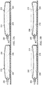
- the compressible bladder system 138 includes a pair of compressible bladders 210.
- Each compressible bladder 210 includes a chamber wall 214 that substantially encloses a chamber 218.
- the compressible bladder 210 is movable between an expanded position (see FIG. 3A ) and a compressed position (see FIG. 3B ).
- a biasing member 224 or resilient member, is disposed within the chamber 218 to bias the compressible bladder 210 toward the expanded position.
- the biasing member 224 is an open-cell foam such as, for example, a reticulated polyurethane foam similar to that used with the distribution manifold 122.
- the biasing member may be a spring, sponge, or any other type of resilient material or structure that is capable of returning the compressible bladder 210 to the expanded position following compression of the compressible bladder 210.
- the biasing member 224 may be positioned external of the chamber 218 and still have a biasing effect that urges the compressible bladder 210 toward the expanded position.
- the biasing member 224 may include a resilient material that is bonded, welded, or other attached to or integrated into the chamber wall 214 that causes the chamber wall 214 to resiliently return to the expanded position.
- the biasing member 224 may include the chamber wall 214 without additional structures, components, or materials. More specifically, if the chamber wall 214 is made from a sufficiently resilient material, the chamber wall 214 may attempt to return the compressible bladder 210 to the expanded position after the compressive force has been removed.
- each compressible bladder 210 includes an inlet 230 and an outlet 234.
- An inlet valve 240 is in fluid communication with the inlet 230 to prevent fluid exiting the chamber 218 from passing through the inlet 230.
- An outlet valve 244 is in fluid communication with the outlet 234 to prevent fluid from entering the chamber 218 through the outlet 234.
- the inlet valve 240 and outlet valve 244 may be positioned in conduits fluidly connected to the inlet 230 and outlet 234, respectively, as shown in FIG. 2 .
- the inlet valve 240 and outlet valve 244 may be more directly associated with or positioned within inlet and outlet ports on the compressible bladder 210.
- the inlet valve 240 and outlet valve 244 may be any particular type of valve for selectively inhibiting or preventing fluid flow, but in one embodiment, the valves 240, 244 are one-way valves such as check valves to allow fluid flow in one direction and prevent fluid flow in another direction.
- a check valve that may be used with the compressible bladders 210 is a flapper-type valve that includes a flapper positioned over an aperture in the chamber wall 214. As fluid pressure on one side of the aperture builds, the flapper moves to an open position to allow fluid communication through the aperture. As fluid pressure on the other side of the aperture increases, the flapper is moved against the aperture to block fluid communication.
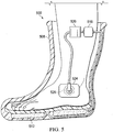
- the compressible bladders 210 are positioned beneath a foot 310 of a user.
- One of the compressible bladders 210 is preferably positioned under a heel region 314 of the foot 310, and another of the compressible bladders 210 is preferably positioned under a forefoot region 318 of the foot 310.
- gas e.g. air
- the gas that is ejected from the chamber 218 is prevented from exiting the inlet 230 due to the presence of the inlet valve 240.
- the compressible bladder 210 begins to move toward the expanded position. The movement of the compressible bladder 210 toward the expanded position is aided by the biasing member 224.
- a volume of the chamber 218 increases, which creates a reduced pressure within the chamber 218 relative to ambient pressure surrounding the compressible bladder 210.
- This reduced pressure within the chamber 218 pulls fluid into the chamber 218 through the inlet valve 240 and the inlet 230. Fluid is prevented from entering the chamber 218 through the outlet 234 due to the presence of the outlet valve 244.
- the reduced pressure generated by the compressible bladder 210 during expansion may be transmitted to the distribution manifold 122 by fluidly connecting the manifold 122 to the inlet 230 of the compressible bladder 210.
- the positioning of the compressible bladders 210 under the heel region 314 and forefoot region 318 of the foot 310 allows a more consistent application of reduced pressure as the user cyclically applies weight to the heel region 314 and then to the forefoot region 318.
- Such a regimen of weight distribution is consistent with normal walking or running activities, and the compressible bladder system 138 is particularly suited for generating reduced pressure while a user is walking or running.
- the compressible bladder 210 under the heel region 314 compresses to the compressed position.
- the compressible bladder 210 under the forefoot region 318 compresses to the compressed position.
- the shifting of weight to the forefoot region 318 relieves the compressive force on the compressible bladder 210 near the heel region 314, thereby allowing the compressible bladder 210 under the heel region to expand and generate reduced pressure.
- the compressible bladder 210 under the forefoot region 318 expands, thereby generating reduced pressure. This cycle continues as the user continues walking, which permits a generation of reduced pressure.
- a compressible bladder system 408 similar to compressible bladder system 138 is illustrated.
- the compressible bladder system 138 includes a pair of compressible bladders 410.
- Each compressible bladder 410 includes a chamber wall 414 that substantially encloses a chamber 418.
- the compressible bladder 410 is movable between an expanded position and a compressed position similar to those previously described with reference to FIGS. 3A and 3B .
- a biasing member, or resilient member, (not shown) is disposed within the chamber 418 to bias the compressible bladder 410 toward the expanded position.
- the biasing member is similar in structure and function to the biasing member 224 previously described.
- the chamber 418 of each compressible bladder 410 includes an inlet 430 and an outlet 434.
- An inlet valve 440 is in fluid communication with the inlet 430 to prevent fluid exiting the chamber 418 from passing through the inlet 430.
- An outlet valve 444 is in fluid communication with the outlet 434 to prevent fluid from entering the chamber 418 through the outlet 434.
- the inlet valve 440 and outlet valve 444 may be positioned in conduits fluidly connected to the inlet 430 and outlet 434, respectively, as shown in FIG. 4 .
- the inlet valve 440 and outlet valve 444 may be more directly associated with or positioned within inlet and outlet ports on the compressible bladder 410.
- the inlet valve 440 and outlet valve 444 are similar in structure and function to the valves previously described herein.
- the compressible bladder system 408 includes a pressure regulator 460 having a first variable-volume cavity 464 and a second variable-volume cavity 468.
- the cavities 460, 468 share a common piston wall 472 that is movable between a retracted position (not shown) and an extended position (see FIG. 4 ) to vary the volume associated with the cavities 460, 468.
- the cavities 460, 468 are fluidly separated from each other by a divider 476.
- the divider 476 may be a bellows that is formed from a sufficiently resilient material.
- Each of the cavities 460, 468 includes an outlet (not shown) and a one-way valve (not shown) so that air or other gases within the cavities 460, 468 may be expelled from the cavities 460, 468 when the piston wall 472 is moved to a retracted position.
- a user may place the piston wall 472 in the retracted position by exerting a compressive force on the piston wall.
- each compressible bladder 410 is fluidly connected to the first variable-volume cavity 468.
- the positively pressured gas from the outlet 434 may bias the piston wall 472 toward the extended position (see FIG.4 ).
- the volume of the second variable-volume cavity 468 increases, which generates a reduced pressure within the second variable-volume cavity 468.
- the reduced pressure generated by the compressible bladders 410 and pressure regulator 460 during expansion of the second variable-volume cavity 468 may be transmitted to the distribution manifold 122 by fluidly connecting the manifold 122 to the second variable-volume cavity 468 of the pressure regulator 460.
- a reduced pressure treatment system 500 includes an article of footwear 508 having a compressible bladder system 512 which may be similar to any of the compressible bladder systems described herein.
- the compressible bladder system 512 is fluidly connected to a pressure regulator 516 and a canister 520.
- the canister 520 may be fluidly connected to a reduced pressure dressing 524 positioned at a tissue site 528.
- the reduced pressure generated by the compressible bladder system 512 and/or the pressure regulator 516 is delivered to the tissue site 528 through the reduced pressure dressing 524, which preferably includes a distribution manifold (not shown).
- tissue site 528 has been illustrated on a side of a foot stabilized within the article of footwear 508, the tissue site 528 may instead be located in the plantar region of the foot or on any other region of the foot or lower extremities. Alternatively, the tissue site 528 may be located on other parts of the body.
- the article of footwear 508 may be an offloading boat, cast walker, neuropathic walker, or any other type of orthotic or therapeutic footwear.
- the article of footwear 508 is particularly well suited, when equipped with the compressible bladder system 512 to treat diabetic foot ulcers and other foot-related injuries and wounds.
- the article of footwear 508 may be designed to relieve pressure in injured areas of the foot of a patient, thereby allowing the patient to remain ambulatory.
- the compressible bladder system 512 is activated as previously described to generate reduced pressure. This reduced pressure may be directed to the injuries or wounds of the patient to improve healing through reduced pressure treatment.
- a method for providing a reduced pressure to a reduced pressure tissue treatment system used by a user includes compressing a compressible bladder with a foot of the user, and generating the reduced pressure within a chamber of the compressible bladder as the compressible bladder expands.
- the compressible bladder may be similar to any of the compressible bladders or compressible bladder systems described herein.
- the method may further include compressing a second compressible bladder with the foot of the user and generating a second reduced pressure within a second chamber of the second compressible bladder as the second compressible bladder expands.
- the second reduced pressure may be substantially the same as the first reduced pressure, or alternatively may be a higher or lower pressure.
- the first compressible bladder is positioned under a forefoot region of the foot and is compressed when the user places weight on the forefoot region.
- the second compressible bladder is positioned under a heel region of the foot and is compressed when the user places weight on the heel region. In this manner, both of the compressible bladders are compressed and expanded during a single stride of the user while walking.
- each of the compressible bladders is fluidly independent, and each compressible bladder includes one-way valves or devices associated with the inlet and outlet of the compressible bladder.
- the pressure regulators described herein may serve to regulate or control the pressure supplied by the compressible bladder system.
- the pressure regulator may further be used to provide a reduced pressure to a tissue site when a positive pressure is supplied to the pressure regulator. While the use of pressure regulators may be preferred in some embodiments, in other embodiments, a pressure regulator may be omitted.
- the compressible bladder may be configured to be self-regulating based on the sizing, shape, and material used for the compressible bladder and the biasing member.
- the compressible bladder continues to supply additional reduced pressure as long as the resiliency of the biasing member or the chamber wall of the compressible bladder is able to overcome the tendency of the compressible bladder to remain collapsed.
- the biasing member or chamber wall is no longer able to expand following compression due to the amount of reduced pressure in the conduit leading to the tissue site, the compressible bladder will no longer generate additional reduced pressure.
Landscapes
- Health & Medical Sciences (AREA)
- Heart & Thoracic Surgery (AREA)
- Animal Behavior & Ethology (AREA)
- General Health & Medical Sciences (AREA)
- Anesthesiology (AREA)
- Biomedical Technology (AREA)
- Hematology (AREA)
- Life Sciences & Earth Sciences (AREA)
- Veterinary Medicine (AREA)
- Engineering & Computer Science (AREA)
- Public Health (AREA)
- Vascular Medicine (AREA)
- Otolaryngology (AREA)
- Media Introduction/Drainage Providing Device (AREA)
- Surgical Instruments (AREA)
- External Artificial Organs (AREA)
Priority Applications (2)
| Application Number | Priority Date | Filing Date | Title |
|---|---|---|---|
| EP12160167.8A EP2468322B1 (en) | 2008-03-13 | 2009-03-13 | System for reduced pressure treatment |
| EP12160169.4A EP2468323B1 (en) | 2008-03-13 | 2009-03-13 | System for reduced pressure treatment |
Applications Claiming Priority (2)
| Application Number | Priority Date | Filing Date | Title |
|---|---|---|---|
| US3639108P | 2008-03-13 | 2008-03-13 | |
| PCT/US2009/037111 WO2009114775A1 (en) | 2008-03-13 | 2009-03-13 | System and method for reduced pressure charging |
Related Child Applications (4)
| Application Number | Title | Priority Date | Filing Date |
|---|---|---|---|
| EP12160167.8A Division EP2468322B1 (en) | 2008-03-13 | 2009-03-13 | System for reduced pressure treatment |
| EP12160167.8A Division-Into EP2468322B1 (en) | 2008-03-13 | 2009-03-13 | System for reduced pressure treatment |
| EP12160169.4A Division EP2468323B1 (en) | 2008-03-13 | 2009-03-13 | System for reduced pressure treatment |
| EP12160169.4A Division-Into EP2468323B1 (en) | 2008-03-13 | 2009-03-13 | System for reduced pressure treatment |
Publications (2)
| Publication Number | Publication Date |
|---|---|
| EP2262548A1 EP2262548A1 (en) | 2010-12-22 |
| EP2262548B1 true EP2262548B1 (en) | 2018-09-26 |
Family
ID=40785382
Family Applications (3)
| Application Number | Title | Priority Date | Filing Date |
|---|---|---|---|
| EP09719686.9A Not-in-force EP2262548B1 (en) | 2008-03-13 | 2009-03-13 | System for reduced pressure charging |
| EP12160169.4A Not-in-force EP2468323B1 (en) | 2008-03-13 | 2009-03-13 | System for reduced pressure treatment |
| EP12160167.8A Ceased EP2468322B1 (en) | 2008-03-13 | 2009-03-13 | System for reduced pressure treatment |
Family Applications After (2)
| Application Number | Title | Priority Date | Filing Date |
|---|---|---|---|
| EP12160169.4A Not-in-force EP2468323B1 (en) | 2008-03-13 | 2009-03-13 | System for reduced pressure treatment |
| EP12160167.8A Ceased EP2468322B1 (en) | 2008-03-13 | 2009-03-13 | System for reduced pressure treatment |
Country Status (13)
| Country | Link |
|---|---|
| US (3) | US8366644B2 (enExample) |
| EP (3) | EP2262548B1 (enExample) |
| JP (2) | JP5122658B2 (enExample) |
| KR (1) | KR20100129764A (enExample) |
| CN (1) | CN101959545B (enExample) |
| AU (1) | AU2009223234B2 (enExample) |
| BR (1) | BRPI0906141A2 (enExample) |
| CA (1) | CA2716486C (enExample) |
| IL (1) | IL207780A0 (enExample) |
| RU (1) | RU2010138980A (enExample) |
| TW (1) | TW200946152A (enExample) |
| WO (1) | WO2009114775A1 (enExample) |
| ZA (1) | ZA201007284B (enExample) |
Families Citing this family (71)
| Publication number | Priority date | Publication date | Assignee | Title |
|---|---|---|---|---|
| GB0325126D0 (en) | 2003-10-28 | 2003-12-03 | Smith & Nephew | Apparatus with heat |
| US7909805B2 (en) | 2004-04-05 | 2011-03-22 | Bluesky Medical Group Incorporated | Flexible reduced pressure treatment appliance |
| US10058642B2 (en) | 2004-04-05 | 2018-08-28 | Bluesky Medical Group Incorporated | Reduced pressure treatment system |
| GB0409444D0 (en) * | 2004-04-28 | 2004-06-02 | Smith & Nephew | Apparatus |
| US8529548B2 (en) | 2004-04-27 | 2013-09-10 | Smith & Nephew Plc | Wound treatment apparatus and method |
| CN101600464A (zh) | 2006-10-17 | 2009-12-09 | 蓝天医疗集团有限公司 | 辅助动力负压伤口治疗装置和方法 |
| JP5613566B2 (ja) | 2007-11-21 | 2014-10-22 | スミス アンド ネフュー ピーエルシーSmith & Nephew Public Limited Company | 創傷被覆材 |
| ES2715605T3 (es) | 2007-11-21 | 2019-06-05 | Smith & Nephew | Apósito para heridas |
| RU2010135033A (ru) | 2008-03-05 | 2012-04-10 | КейСиАй Лайсензинг Инк. (US) | Повязка и способ приложения пониженного давления к участку ткани и сбора и хранения текучей среды от участка ткани |
| EP2262548B1 (en) * | 2008-03-13 | 2018-09-26 | KCI Licensing, Inc. | System for reduced pressure charging |
| EP2326293B1 (en) | 2008-05-15 | 2015-12-16 | Ossur HF | Circumferential walker |
| GB2470938B (en) * | 2009-06-09 | 2013-07-03 | Polarseal Tapes & Conversions | Actuating apparatus |
| US8814842B2 (en) | 2010-03-16 | 2014-08-26 | Kci Licensing, Inc. | Delivery-and-fluid-storage bridges for use with reduced-pressure systems |
| US20120203144A1 (en) * | 2011-02-07 | 2012-08-09 | Kci Licensing, Inc. | Methods and systems for treating a hoof on an ungulate mammal |
| US9198803B1 (en) | 2011-09-26 | 2015-12-01 | David S. London | Dressing device for offloading and treating an ulcer |
| US9861532B2 (en) | 2011-12-16 | 2018-01-09 | Kci Licensing, Inc. | Releasable medical drapes |
| US10940047B2 (en) | 2011-12-16 | 2021-03-09 | Kci Licensing, Inc. | Sealing systems and methods employing a hybrid switchable drape |
| CA3260090A1 (en) | 2012-03-12 | 2025-05-16 | Smith & Nephew Plc | Reduced pressure apparatus and methods |
| US9144530B2 (en) | 2012-05-17 | 2015-09-29 | Nike, Inc. | Compressive therapeutic device |
| GB201216928D0 (en) | 2012-09-21 | 2012-11-07 | I2R Medical Ltd | Portable medical device system |
| WO2014078518A1 (en) | 2012-11-16 | 2014-05-22 | Kci Licensing, Inc. | Medical drape with pattern adhesive layers and method of manufacturing same |
| WO2015042214A1 (en) | 2013-09-18 | 2015-03-26 | Ossur Hf | Insole for an orthopedic device |
| US9668907B2 (en) | 2013-09-25 | 2017-06-06 | Ossur Iceland Ehf | Orthopedic device |
| US9839548B2 (en) | 2013-09-25 | 2017-12-12 | Ossur Iceland Ehf | Orthopedic device |
| US9839550B2 (en) | 2013-09-25 | 2017-12-12 | Ossur Hf | Orthopedic device |
| EP3062753B1 (en) | 2013-10-28 | 2018-11-21 | KCI Licensing, Inc. | Hybrid sealing tape |
| WO2015065615A1 (en) | 2013-10-30 | 2015-05-07 | Kci Licensing, Inc. | Absorbent conduit and system |
| EP3384883B1 (en) | 2013-10-30 | 2021-02-24 | 3M Innovative Properties Company | Dressing with diffrentially sized perforations |
| WO2015065616A1 (en) | 2013-10-30 | 2015-05-07 | Kci Licensing, Inc. | Dressing with sealing and retention intereface |
| EP3513773A1 (en) | 2013-10-30 | 2019-07-24 | KCI Licensing, Inc. | Condensate absorbing and dissipating system |
| EP3079638B1 (en) | 2013-12-12 | 2018-03-07 | Ossur Iceland EHF | Outsole for orthopedic device |
| US11026844B2 (en) | 2014-03-03 | 2021-06-08 | Kci Licensing, Inc. | Low profile flexible pressure transmission conduit |
| USD742017S1 (en) | 2014-03-27 | 2015-10-27 | Ossur Hf | Shell for an orthopedic device |
| JP6640748B2 (ja) | 2014-06-05 | 2020-02-05 | ケーシーアイ ライセンシング インコーポレイテッド | 流体獲得および分配特徴を備えるドレッシング |
| EP3233001B1 (en) | 2014-12-17 | 2020-06-17 | KCI Licensing, Inc. | Dressing with offloading capability |
| WO2016123049A1 (en) * | 2015-01-26 | 2016-08-04 | Ossur Iceland Ehf | Negative pressure wound therapy orthopedic device |
| CN113367890B (zh) | 2015-04-27 | 2023-02-21 | 史密夫及内修公开有限公司 | 减压装置 |
| WO2016182977A1 (en) * | 2015-05-08 | 2016-11-17 | Kci Licensing, Inc. | Low acuity dressing with integral pump |
| WO2017040045A1 (en) | 2015-09-01 | 2017-03-09 | Kci Licensing, Inc. | Dressing with increased apposition force |
| EP3892310B1 (en) | 2015-09-17 | 2025-10-29 | Solventum Intellectual Properties Company | Hybrid silicone and acrylic adhesive cover for use with wound treatment |
| US11324639B2 (en) * | 2015-09-21 | 2022-05-10 | Brigham And Women's Hospital, Inc. | Negative pressure wound treatment system and method |
| CA3016484A1 (en) | 2016-03-07 | 2017-09-14 | Smith & Nephew Plc | Wound treatment apparatuses and methods with negative pressure source integrated into wound dressing |
| CN114469523A (zh) | 2016-04-26 | 2022-05-13 | 史密夫及内修公开有限公司 | 与具有流体侵入抑制部件的一体化负压源一起使用的伤口敷料和方法 |
| CN109069711A (zh) | 2016-05-03 | 2018-12-21 | 史密夫及内修公开有限公司 | 用于在负压力治疗系统中驱动负压源的系统和方法 |
| CA3038206A1 (en) | 2016-05-03 | 2017-11-09 | Smith & Nephew Plc | Optimizing power transfer to negative pressure sources in negative pressure therapy systems |
| US11096831B2 (en) | 2016-05-03 | 2021-08-24 | Smith & Nephew Plc | Negative pressure wound therapy device activation and control |
| CN109561994B (zh) | 2016-08-25 | 2022-03-15 | 史密夫及内修公开有限公司 | 吸收性负压伤口疗法敷料 |
| CN106174873A (zh) * | 2016-08-29 | 2016-12-07 | 琪尔特有限公司 | 一种智能矫正鞋垫 |
| JP2019528957A (ja) | 2016-09-30 | 2019-10-17 | スミス アンド ネフュー ピーエルシーSmith & Nephew Public Limited Company | 一体化された電子機器を備えた陰圧創傷治療装置及び方法 |
| WO2019053101A1 (en) | 2017-09-13 | 2019-03-21 | Smith & Nephew Plc | APPARATUS AND METHODS FOR NEGATIVE PRESSURE WOUND TREATMENT WITH INTEGRATED ELECTRONICS |
| WO2018060417A1 (en) | 2016-09-30 | 2018-04-05 | Smith & Nephew Plc | Negative pressure wound treatment apparatuses and methods with integrated electronics |
| CA3046416A1 (en) | 2016-12-12 | 2018-06-21 | Smith & Nephew Plc | Pressure wound therapy status indication via external device |
| EP3592312B1 (en) | 2017-03-08 | 2024-01-10 | Smith & Nephew plc | Negative pressure wound therapy device control in presence of fault condition |
| WO2018206420A1 (en) | 2017-05-09 | 2018-11-15 | Smith & Nephew Plc | Redundant controls for negative pressure wound therapy systems |
| GB201718070D0 (en) | 2017-11-01 | 2017-12-13 | Smith & Nephew | Negative pressure wound treatment apparatuses and methods with integrated electronics |
| GB201718072D0 (en) | 2017-11-01 | 2017-12-13 | Smith & Nephew | Negative pressure wound treatment apparatuses and methods with integrated electronics |
| US11497653B2 (en) | 2017-11-01 | 2022-11-15 | Smith & Nephew Plc | Negative pressure wound treatment apparatuses and methods with integrated electronics |
| GB201718054D0 (en) | 2017-11-01 | 2017-12-13 | Smith & Nephew | Sterilization of integrated negative pressure wound treatment apparatuses and sterilization methods |
| WO2019152906A1 (en) | 2018-02-02 | 2019-08-08 | Ossur Iceland Ehf | Orthopedic walker |
| WO2019157466A1 (en) | 2018-02-12 | 2019-08-15 | Healyx Labs, Inc. | Negative pressure wound therapy systems, devices, and methods |
| CN112165961A (zh) | 2018-04-02 | 2021-01-01 | Ic外科公司 | 负压泵及相关方法 |
| US12178777B2 (en) | 2018-08-01 | 2024-12-31 | Solventum Intellectual Properties Company | Soft-tissue treatment with negative pressure |
| USD898925S1 (en) | 2018-09-13 | 2020-10-13 | Smith & Nephew Plc | Medical dressing |
| GB201903774D0 (en) | 2019-03-20 | 2019-05-01 | Smith & Nephew | Negative pressure wound treatment apparatuses and methods with integrated electronics |
| EP3946500B1 (en) | 2019-03-29 | 2025-10-08 | Solventum Intellectual Properties Company | Negative-pressure treatment with area stabilization |
| US12268805B2 (en) | 2019-03-29 | 2025-04-08 | Kci Licensing, Inc. | Dressing with integrated pump and releasably coupled pump actuator |
| CN113660918A (zh) * | 2019-03-29 | 2021-11-16 | 凯希特许有限公司 | 具有区域稳定性的负压治疗 |
| GB201907716D0 (en) | 2019-05-31 | 2019-07-17 | Smith & Nephew | Systems and methods for extending operational time of negative pressure wound treatment apparatuses |
| US12035779B2 (en) | 2020-05-28 | 2024-07-16 | Nike, Inc. | Foot support systems including fluid movement controllers and adjustable foot support pressure |
| US12208197B2 (en) * | 2020-12-11 | 2025-01-28 | Hisham Alshaer | Manually operated negative pressure wound treatment apparatus coupled with smart feedback system |
| KR102594468B1 (ko) * | 2022-09-16 | 2023-10-25 | 가톨릭관동대학교산학협력단 | 음압 드레싱 시스템 |
Citations (1)
| Publication number | Priority date | Publication date | Assignee | Title |
|---|---|---|---|---|
| US20070066946A1 (en) * | 2005-09-07 | 2007-03-22 | Kurt Haggstrom | Wound dressing with vacuum reservoir |
Family Cites Families (146)
| Publication number | Priority date | Publication date | Assignee | Title |
|---|---|---|---|---|
| US1355846A (en) | 1920-02-06 | 1920-10-19 | David A Rannells | Medical appliance |
| US2547758A (en) | 1949-01-05 | 1951-04-03 | Wilmer B Keeling | Instrument for treating the male urethra |
| US2632443A (en) | 1949-04-18 | 1953-03-24 | Eleanor P Lesher | Surgical dressing |
| GB692578A (en) | 1949-09-13 | 1953-06-10 | Minnesota Mining & Mfg | Improvements in or relating to drape sheets for surgical use |
| US2682873A (en) | 1952-07-30 | 1954-07-06 | Johnson & Johnson | General purpose protective dressing |
| NL189176B (nl) | 1956-07-13 | 1900-01-01 | Hisamitsu Pharmaceutical Co | Pleister op basis van een synthetische rubber. |
| US2969057A (en) | 1957-11-04 | 1961-01-24 | Brady Co W H | Nematodic swab |
| US3066672A (en) | 1960-09-27 | 1962-12-04 | Jr William H Crosby | Method and apparatus for serial sampling of intestinal juice |
| DE1848689U (de) * | 1961-12-22 | 1962-03-22 | Medizintechnik Leipzig Veb | Saugpumpe zum absaugen von sekreten aus den atmungskanaelen. |
| US3367332A (en) | 1965-08-27 | 1968-02-06 | Gen Electric | Product and process for establishing a sterile area of skin |
| US3520300A (en) | 1967-03-15 | 1970-07-14 | Amp Inc | Surgical sponge and suction device |
| US3568692A (en) * | 1967-11-27 | 1971-03-09 | Bowles Eng Corp | Optical machining process |
| US3568675A (en) | 1968-08-30 | 1971-03-09 | Clyde B Harvey | Fistula and penetrating wound dressing |
| US3682180A (en) | 1970-06-08 | 1972-08-08 | Coilform Co Inc | Drain clip for surgical drain |
| BE789293Q (fr) | 1970-12-07 | 1973-01-15 | Parke Davis & Co | Pansement medico-chirugical pour brulures et lesions analogues |
| US3826254A (en) | 1973-02-26 | 1974-07-30 | Verco Ind | Needle or catheter retaining appliance |
| US3809087A (en) * | 1973-05-17 | 1974-05-07 | R Lewis | Closed wound suction apparatus having biased plate members |
| DE2527706A1 (de) | 1975-06-21 | 1976-12-30 | Hanfried Dr Med Weigand | Einrichtung zum einleiten von kontrastmittel in einen kuenstlichen darmausgang |
| DE2640413C3 (de) | 1976-09-08 | 1980-03-27 | Richard Wolf Gmbh, 7134 Knittlingen | Katheter-Überwachungsgerät |
| NL7710909A (nl) | 1976-10-08 | 1978-04-11 | Smith & Nephew | Samengestelde hechtstrook. |
| GB1562244A (en) | 1976-11-11 | 1980-03-05 | Lock P M | Wound dressing materials |
| US4080970A (en) | 1976-11-17 | 1978-03-28 | Miller Thomas J | Post-operative combination dressing and internal drain tube with external shield and tube connector |
| US4139004A (en) | 1977-02-17 | 1979-02-13 | Gonzalez Jr Harry | Bandage apparatus for treating burns |
| US4184510A (en) | 1977-03-15 | 1980-01-22 | Fibra-Sonics, Inc. | Valued device for controlling vacuum in surgery |
| US4165748A (en) | 1977-11-07 | 1979-08-28 | Johnson Melissa C | Catheter tube holder |
| US4245637A (en) | 1978-07-10 | 1981-01-20 | Nichols Robert L | Shutoff valve sleeve |
| SE414994B (sv) | 1978-11-28 | 1980-09-01 | Landstingens Inkopscentral | Venkateterforband |
| WO1980001139A1 (en) | 1978-12-06 | 1980-06-12 | Svedman Paul | Device for treating tissues,for example skin |
| US4266545A (en) | 1979-04-06 | 1981-05-12 | Moss James P | Portable suction device for collecting fluids from a closed wound |
| US4284079A (en) | 1979-06-28 | 1981-08-18 | Adair Edwin Lloyd | Method for applying a male incontinence device |
| US4261363A (en) | 1979-11-09 | 1981-04-14 | C. R. Bard, Inc. | Retention clips for body fluid drains |
| US4569348A (en) | 1980-02-22 | 1986-02-11 | Velcro Usa Inc. | Catheter tube holder strap |
| US4480638A (en) | 1980-03-11 | 1984-11-06 | Eduard Schmid | Cushion for holding an element of grafted skin |
| US4297995A (en) | 1980-06-03 | 1981-11-03 | Key Pharmaceuticals, Inc. | Bandage containing attachment post |
| US4333468A (en) | 1980-08-18 | 1982-06-08 | Geist Robert W | Mesentery tube holder apparatus |
| US4465485A (en) | 1981-03-06 | 1984-08-14 | Becton, Dickinson And Company | Suction canister with unitary shut-off valve and filter features |
| US4392853A (en) | 1981-03-16 | 1983-07-12 | Rudolph Muto | Sterile assembly for protecting and fastening an indwelling device |
| US4373519A (en) | 1981-06-26 | 1983-02-15 | Minnesota Mining And Manufacturing Company | Composite wound dressing |
| US4392858A (en) | 1981-07-16 | 1983-07-12 | Sherwood Medical Company | Wound drainage device |
| US4419097A (en) | 1981-07-31 | 1983-12-06 | Rexar Industries, Inc. | Attachment for catheter tube |
| AU550575B2 (en) | 1981-08-07 | 1986-03-27 | Richard Christian Wright | Wound drainage device |
| SE429197B (sv) | 1981-10-14 | 1983-08-22 | Frese Nielsen | Anordning for behandling av sar |
| DE3146266A1 (de) | 1981-11-21 | 1983-06-01 | B. Braun Melsungen Ag, 3508 Melsungen | Kombinierte vorrichtung fuer eine medizinische saugdrainage |
| US4551139A (en) | 1982-02-08 | 1985-11-05 | Marion Laboratories, Inc. | Method and apparatus for burn wound treatment |
| US4475909A (en) | 1982-05-06 | 1984-10-09 | Eisenberg Melvin I | Male urinary device and method for applying the device |
| EP0100148B1 (en) | 1982-07-06 | 1986-01-08 | Dow Corning Limited | Medical-surgical dressing and a process for the production thereof |
| NZ206837A (en) | 1983-01-27 | 1986-08-08 | Johnson & Johnson Prod Inc | Thin film adhesive dressing:backing material in three sections |
| US4548202A (en) | 1983-06-20 | 1985-10-22 | Ethicon, Inc. | Mesh tissue fasteners |
| US4540412A (en) | 1983-07-14 | 1985-09-10 | The Kendall Company | Device for moist heat therapy |
| US4543100A (en) | 1983-11-01 | 1985-09-24 | Brodsky Stuart A | Catheter and drain tube retainer |
| US4525374A (en) | 1984-02-27 | 1985-06-25 | Manresa, Inc. | Treating hydrophobic filters to render them hydrophilic |
| CA1286177C (en) | 1984-05-03 | 1991-07-16 | Smith And Nephew Associated Companies Plc | Adhesive wound dressing |
| US4897081A (en) | 1984-05-25 | 1990-01-30 | Thermedics Inc. | Percutaneous access device |
| US5215522A (en) | 1984-07-23 | 1993-06-01 | Ballard Medical Products | Single use medical aspirating device and method |
| GB8419745D0 (en) | 1984-08-02 | 1984-09-05 | Smith & Nephew Ass | Wound dressing |
| US4872450A (en) | 1984-08-17 | 1989-10-10 | Austad Eric D | Wound dressing and method of forming same |
| US4655754A (en) | 1984-11-09 | 1987-04-07 | Stryker Corporation | Vacuum wound drainage system and lipids baffle therefor |
| US4826494A (en) | 1984-11-09 | 1989-05-02 | Stryker Corporation | Vacuum wound drainage system |
| US4605399A (en) | 1984-12-04 | 1986-08-12 | Complex, Inc. | Transdermal infusion device |
| US5037397A (en) | 1985-05-03 | 1991-08-06 | Medical Distributors, Inc. | Universal clamp |
| US4640688A (en) | 1985-08-23 | 1987-02-03 | Mentor Corporation | Urine collection catheter |
| US4710165A (en) | 1985-09-16 | 1987-12-01 | Mcneil Charles B | Wearable, variable rate suction/collection device |
| US4758220A (en) | 1985-09-26 | 1988-07-19 | Alcon Laboratories, Inc. | Surgical cassette proximity sensing and latching apparatus |
| US4733659A (en) | 1986-01-17 | 1988-03-29 | Seton Company | Foam bandage |
| EP0256060A1 (en) | 1986-01-31 | 1988-02-24 | OSMOND, Roger L. W. | Suction system for wound and gastro-intestinal drainage |
| US4838883A (en) | 1986-03-07 | 1989-06-13 | Nissho Corporation | Urine-collecting device |
| JPS62281965A (ja) | 1986-05-29 | 1987-12-07 | テルモ株式会社 | カテ−テルおよびカテ−テル用固定部材 |
| GB8621884D0 (en) | 1986-09-11 | 1986-10-15 | Bard Ltd | Catheter applicator |
| GB2195255B (en) | 1986-09-30 | 1991-05-01 | Vacutec Uk Limited | Apparatus for vacuum treatment of an epidermal surface |
| US4743232A (en) | 1986-10-06 | 1988-05-10 | The Clinipad Corporation | Package assembly for plastic film bandage |
| DE3634569A1 (de) | 1986-10-10 | 1988-04-21 | Sachse Hans E | Kondomkatheter, ein harnroehrenkatheter zur verhinderung von aufsteigenden infektionen |
| JPS63135179A (ja) | 1986-11-26 | 1988-06-07 | 立花 俊郎 | 薬物の経皮投与具 |
| GB8628564D0 (en) | 1986-11-28 | 1987-01-07 | Smiths Industries Plc | Anti-foaming agent suction apparatus |
| GB8706116D0 (en) | 1987-03-14 | 1987-04-15 | Smith & Nephew Ass | Adhesive dressings |
| US4787888A (en) | 1987-06-01 | 1988-11-29 | University Of Connecticut | Disposable piezoelectric polymer bandage for percutaneous delivery of drugs and method for such percutaneous delivery (a) |
| US4863449A (en) | 1987-07-06 | 1989-09-05 | Hollister Incorporated | Adhesive-lined elastic condom cathether |
| US5176663A (en) | 1987-12-02 | 1993-01-05 | Pal Svedman | Dressing having pad with compressibility limiting elements |
| US4906240A (en) | 1988-02-01 | 1990-03-06 | Matrix Medica, Inc. | Adhesive-faced porous absorbent sheet and method of making same |
| US4985019A (en) | 1988-03-11 | 1991-01-15 | Michelson Gary K | X-ray marker |
| GB8812803D0 (en) | 1988-05-28 | 1988-06-29 | Smiths Industries Plc | Medico-surgical containers |
| US4919654A (en) | 1988-08-03 | 1990-04-24 | Kalt Medical Corporation | IV clamp with membrane |
| US5000741A (en) | 1988-08-22 | 1991-03-19 | Kalt Medical Corporation | Transparent tracheostomy tube dressing |
| EP0379416B1 (fr) | 1989-01-16 | 1995-03-08 | Roussel-Uclaf | Dérivés d'azabicycloheptène et leurs sels, leur procédé de préparation, leur application comme médicaments et les compositions les renfermant |
| GB8906100D0 (en) | 1989-03-16 | 1989-04-26 | Smith & Nephew | Laminates |
| US5100396A (en) | 1989-04-03 | 1992-03-31 | Zamierowski David S | Fluidic connection system and method |
| US4969880A (en) | 1989-04-03 | 1990-11-13 | Zamierowski David S | Wound dressing and treatment method |
| US5527293A (en) | 1989-04-03 | 1996-06-18 | Kinetic Concepts, Inc. | Fastening system and method |
| US5261893A (en) | 1989-04-03 | 1993-11-16 | Zamierowski David S | Fastening system and method |
| US5358494A (en) | 1989-07-11 | 1994-10-25 | Svedman Paul | Irrigation dressing |
| JP2719671B2 (ja) | 1989-07-11 | 1998-02-25 | 日本ゼオン株式会社 | 創傷被覆材 |
| US5232453A (en) | 1989-07-14 | 1993-08-03 | E. R. Squibb & Sons, Inc. | Catheter holder |
| GB2235877A (en) | 1989-09-18 | 1991-03-20 | Antonio Talluri | Closed wound suction apparatus |
| US5134994A (en) | 1990-02-12 | 1992-08-04 | Say Sam L | Field aspirator in a soft pack with externally mounted container |
| US5092858A (en) | 1990-03-20 | 1992-03-03 | Becton, Dickinson And Company | Liquid gelling agent distributor device |
| JP2941918B2 (ja) | 1990-09-19 | 1999-08-30 | テルモ株式会社 | 秤量装置 |
| US5149331A (en) | 1991-05-03 | 1992-09-22 | Ariel Ferdman | Method and device for wound closure |
| US5278100A (en) | 1991-11-08 | 1994-01-11 | Micron Technology, Inc. | Chemical vapor deposition technique for depositing titanium silicide on semiconductor wafers |
| US5636643A (en) | 1991-11-14 | 1997-06-10 | Wake Forest University | Wound treatment employing reduced pressure |
| US5645081A (en) | 1991-11-14 | 1997-07-08 | Wake Forest University | Method of treating tissue damage and apparatus for same |
| US7198046B1 (en) | 1991-11-14 | 2007-04-03 | Wake Forest University Health Sciences | Wound treatment employing reduced pressure |
| US5279550A (en) | 1991-12-19 | 1994-01-18 | Gish Biomedical, Inc. | Orthopedic autotransfusion system |
| US5167613A (en) | 1992-03-23 | 1992-12-01 | The Kendall Company | Composite vented wound dressing |
| CN2120585U (zh) * | 1992-04-29 | 1992-11-04 | 彭新鸾 | 脚踏式胃肠减压器 |
| FR2690617B1 (fr) | 1992-04-29 | 1994-06-24 | Cbh Textile | Pansement adhesif transparent. |
| US5617650A (en) * | 1992-10-23 | 1997-04-08 | Grim; Tracy E. | Vacuum formed conformable shoe |
| DE4306478A1 (de) | 1993-03-02 | 1994-09-08 | Wolfgang Dr Wagner | Drainagevorrichtung, insbesondere Pleuradrainagevorrichtung, und Drainageverfahren |
| US5342376A (en) | 1993-05-03 | 1994-08-30 | Dermagraphics, Inc. | Inserting device for a barbed tissue connector |
| US6241747B1 (en) | 1993-05-03 | 2001-06-05 | Quill Medical, Inc. | Barbed Bodily tissue connector |
| US5344415A (en) | 1993-06-15 | 1994-09-06 | Deroyal Industries, Inc. | Sterile system for dressing vascular access site |
| US5348530A (en) * | 1993-07-29 | 1994-09-20 | Royce Medical Company | Pneumatic ankle brace with bladder and pump arrangement |
| US5437651A (en) | 1993-09-01 | 1995-08-01 | Research Medical, Inc. | Medical suction apparatus |
| US5549584A (en) | 1994-02-14 | 1996-08-27 | The Kendall Company | Apparatus for removing fluid from a wound |
| US5607388A (en) | 1994-06-16 | 1997-03-04 | Hercules Incorporated | Multi-purpose wound dressing |
| US5556375A (en) | 1994-06-16 | 1996-09-17 | Hercules Incorporated | Wound dressing having a fenestrated base layer |
| US5664270A (en) | 1994-07-19 | 1997-09-09 | Kinetic Concepts, Inc. | Patient interface system |
| ATE270561T1 (de) | 1994-08-22 | 2004-07-15 | Kinetic Concepts Inc | Kanister |
| DE29504378U1 (de) | 1995-03-15 | 1995-09-14 | MTG Medizinisch, technische Gerätebau GmbH, 66299 Friedrichsthal | Elektronisch geregelte Niedervakuumpumpe für die Thorax- und Wunddrainage |
| DE19517699C2 (de) | 1995-05-13 | 1999-11-04 | Wilhelm Fleischmann | Vorrichtung zur Vakuumversiegelung einer Wunde |
| GB9523253D0 (en) | 1995-11-14 | 1996-01-17 | Mediscus Prod Ltd | Portable wound treatment apparatus |
| DE19616954C2 (de) | 1996-04-27 | 2000-02-10 | Heraeus Med Gmbh | Absaugpumpe |
| US6135116A (en) | 1997-07-28 | 2000-10-24 | Kci Licensing, Inc. | Therapeutic method for treating ulcers |
| JPH1142101A (ja) * | 1997-07-28 | 1999-02-16 | Fujio Fujimoto | 換気機能付き靴 |
| AU755496B2 (en) | 1997-09-12 | 2002-12-12 | Kci Licensing, Inc. | Surgical drape and suction head for wound treatment |
| GB9719520D0 (en) | 1997-09-12 | 1997-11-19 | Kci Medical Ltd | Surgical drape and suction heads for wound treatment |
| US6071267A (en) | 1998-02-06 | 2000-06-06 | Kinetic Concepts, Inc. | Medical patient fluid management interface system and method |
| US6488643B1 (en) | 1998-10-08 | 2002-12-03 | Kci Licensing, Inc. | Wound healing foot wrap |
| GB9822341D0 (en) | 1998-10-13 | 1998-12-09 | Kci Medical Ltd | Negative pressure therapy using wall suction |
| US6287316B1 (en) | 1999-03-26 | 2001-09-11 | Ethicon, Inc. | Knitted surgical mesh |
| US6856821B2 (en) | 2000-05-26 | 2005-02-15 | Kci Licensing, Inc. | System for combined transcutaneous blood gas monitoring and vacuum assisted wound closure |
| US7799004B2 (en) | 2001-03-05 | 2010-09-21 | Kci Licensing, Inc. | Negative pressure wound treatment apparatus and infection identification system and method |
| US6006447A (en) | 1999-04-22 | 1999-12-28 | Neal; James R. | Shoe insole with air circulation system |
| US6991643B2 (en) | 2000-12-20 | 2006-01-31 | Usgi Medical Inc. | Multi-barbed device for retaining tissue in apposition and methods of use |
| JP4129536B2 (ja) | 2000-02-24 | 2008-08-06 | ヴェネテック インターナショナル,インコーポレイテッド | 高適合性カテーテルアンカリングシステム |
| US6540705B2 (en) | 2001-02-22 | 2003-04-01 | Core Products International, Inc. | Ankle brace providing upper and lower ankle adjustment |
| US6497669B1 (en) | 2001-06-04 | 2002-12-24 | Rheologics, Inc. | Non-biohazard blood letting system |
| US7004915B2 (en) * | 2001-08-24 | 2006-02-28 | Kci Licensing, Inc. | Negative pressure assisted tissue treatment system |
| US20040010939A1 (en) * | 2001-09-24 | 2004-01-22 | Liu Chang Yuen | Shoes having ventilation devices |
| US6755798B2 (en) * | 2002-02-13 | 2004-06-29 | Aircast, Inc. | Pneumatic achilles sleeve |
| US20040163278A1 (en) * | 2002-11-01 | 2004-08-26 | Caspers Carl A. | Vacuum-suspended shoe |
| US7051456B2 (en) | 2003-07-29 | 2006-05-30 | Nike, Inc. | Article of footwear incorporating an inflatable chamber |
| US8100887B2 (en) * | 2004-03-09 | 2012-01-24 | Bluesky Medical Group Incorporated | Enclosure-based reduced pressure treatment system |
| JP2006116162A (ja) * | 2004-10-25 | 2006-05-11 | Hirosaki Univ | 陰圧閉鎖装置 |
| US7896823B2 (en) * | 2006-01-17 | 2011-03-01 | Theranova, Llc | Method and apparatus for treating wound using negative pressure therapy |
| US8267908B2 (en) * | 2007-02-09 | 2012-09-18 | Kci Licensing, Inc. | Delivery tube, system, and method for storing liquid from a tissue site |
| US7790946B2 (en) * | 2007-07-06 | 2010-09-07 | Tyco Healthcare Group Lp | Subatmospheric pressure wound therapy dressing |
| EP2262548B1 (en) | 2008-03-13 | 2018-09-26 | KCI Licensing, Inc. | System for reduced pressure charging |
-
2009
- 2009-03-13 EP EP09719686.9A patent/EP2262548B1/en not_active Not-in-force
- 2009-03-13 US US12/403,911 patent/US8366644B2/en not_active Expired - Fee Related
- 2009-03-13 TW TW098108348A patent/TW200946152A/zh unknown
- 2009-03-13 EP EP12160169.4A patent/EP2468323B1/en not_active Not-in-force
- 2009-03-13 JP JP2010550891A patent/JP5122658B2/ja not_active Expired - Fee Related
- 2009-03-13 CN CN2009801074207A patent/CN101959545B/zh not_active Expired - Fee Related
- 2009-03-13 KR KR1020107022792A patent/KR20100129764A/ko not_active Abandoned
- 2009-03-13 BR BRPI0906141A patent/BRPI0906141A2/pt not_active IP Right Cessation
- 2009-03-13 CA CA2716486A patent/CA2716486C/en not_active Expired - Fee Related
- 2009-03-13 RU RU2010138980/14A patent/RU2010138980A/ru not_active Application Discontinuation
- 2009-03-13 AU AU2009223234A patent/AU2009223234B2/en not_active Ceased
- 2009-03-13 EP EP12160167.8A patent/EP2468322B1/en not_active Ceased
- 2009-03-13 WO PCT/US2009/037111 patent/WO2009114775A1/en not_active Ceased
-
2010
- 2010-08-24 IL IL207780A patent/IL207780A0/en unknown
- 2010-10-12 ZA ZA2010/07284A patent/ZA201007284B/en unknown
-
2012
- 2012-10-24 JP JP2012234434A patent/JP5878855B2/ja not_active Expired - Fee Related
- 2012-12-27 US US13/728,712 patent/US9827403B2/en active Active
-
2017
- 2017-10-24 US US15/792,265 patent/US10842977B2/en not_active Expired - Fee Related
Patent Citations (1)
| Publication number | Priority date | Publication date | Assignee | Title |
|---|---|---|---|---|
| US20070066946A1 (en) * | 2005-09-07 | 2007-03-22 | Kurt Haggstrom | Wound dressing with vacuum reservoir |
Also Published As
| Publication number | Publication date |
|---|---|
| TW200946152A (en) | 2009-11-16 |
| IL207780A0 (en) | 2010-12-30 |
| JP2013039412A (ja) | 2013-02-28 |
| US10842977B2 (en) | 2020-11-24 |
| US8366644B2 (en) | 2013-02-05 |
| JP5878855B2 (ja) | 2016-03-08 |
| US20090234260A1 (en) | 2009-09-17 |
| JP2011514832A (ja) | 2011-05-12 |
| EP2468322B1 (en) | 2015-10-07 |
| CN101959545A (zh) | 2011-01-26 |
| AU2009223234B2 (en) | 2014-04-24 |
| US9827403B2 (en) | 2017-11-28 |
| EP2468322A1 (en) | 2012-06-27 |
| WO2009114775A1 (en) | 2009-09-17 |
| ZA201007284B (en) | 2011-06-29 |
| CA2716486A1 (en) | 2009-09-17 |
| EP2468323B1 (en) | 2014-10-15 |
| KR20100129764A (ko) | 2010-12-09 |
| CA2716486C (en) | 2017-06-27 |
| EP2468323A1 (en) | 2012-06-27 |
| CN101959545B (zh) | 2013-06-19 |
| US20130116661A1 (en) | 2013-05-09 |
| AU2009223234A1 (en) | 2009-09-17 |
| JP5122658B2 (ja) | 2013-01-16 |
| EP2262548A1 (en) | 2010-12-22 |
| US20180043142A1 (en) | 2018-02-15 |
| RU2010138980A (ru) | 2012-04-20 |
| BRPI0906141A2 (pt) | 2016-06-21 |
Similar Documents
| Publication | Publication Date | Title |
|---|---|---|
| EP2262548B1 (en) | System for reduced pressure charging | |
| US10946122B2 (en) | Manually-actuated reduced pressure treatment system having regulated pressure capabilities | |
| US10786607B2 (en) | Manually-actuated reduced pressure treatment system with audible leak indicator | |
| AU2016231470B2 (en) | Manually-actuated reduced pressure treatment system having regulated pressure capabilities | |
| HK1148490A (en) | System and method for reduced pressure charging | |
| AU2013201594B2 (en) | Manually-actuated reduced pressure pump having regulated pressure capabilities |
Legal Events
| Date | Code | Title | Description |
|---|---|---|---|
| PUAI | Public reference made under article 153(3) epc to a published international application that has entered the european phase |
Free format text: ORIGINAL CODE: 0009012 |
|
| 17P | Request for examination filed |
Effective date: 20100818 |
|
| AK | Designated contracting states |
Kind code of ref document: A1 Designated state(s): AT BE BG CH CY CZ DE DK EE ES FI FR GB GR HR HU IE IS IT LI LT LU LV MC MK MT NL NO PL PT RO SE SI SK TR |
|
| AX | Request for extension of the european patent |
Extension state: AL BA RS |
|
| DAX | Request for extension of the european patent (deleted) | ||
| 17Q | First examination report despatched |
Effective date: 20141014 |
|
| RAP1 | Party data changed (applicant data changed or rights of an application transferred) |
Owner name: KCI LICENSING, INC. |
|
| RAP1 | Party data changed (applicant data changed or rights of an application transferred) |
Owner name: KCI LICENSING, INC. |
|
| STAA | Information on the status of an ep patent application or granted ep patent |
Free format text: STATUS: EXAMINATION IS IN PROGRESS |
|
| RAP1 | Party data changed (applicant data changed or rights of an application transferred) |
Owner name: KCI LICENSING, INC. |
|
| REG | Reference to a national code |
Ref country code: DE Ref legal event code: R079 Ref document number: 602009054734 Country of ref document: DE Free format text: PREVIOUS MAIN CLASS: A61M0001000000 Ipc: A61M0027000000 |
|
| GRAP | Despatch of communication of intention to grant a patent |
Free format text: ORIGINAL CODE: EPIDOSNIGR1 |
|
| STAA | Information on the status of an ep patent application or granted ep patent |
Free format text: STATUS: GRANT OF PATENT IS INTENDED |
|
| RIC1 | Information provided on ipc code assigned before grant |
Ipc: A61M 1/00 20060101ALI20180404BHEP Ipc: A61M 27/00 20060101AFI20180404BHEP |
|
| INTG | Intention to grant announced |
Effective date: 20180508 |
|
| GRAS | Grant fee paid |
Free format text: ORIGINAL CODE: EPIDOSNIGR3 |
|
| GRAA | (expected) grant |
Free format text: ORIGINAL CODE: 0009210 |
|
| STAA | Information on the status of an ep patent application or granted ep patent |
Free format text: STATUS: THE PATENT HAS BEEN GRANTED |
|
| AK | Designated contracting states |
Kind code of ref document: B1 Designated state(s): AT BE BG CH CY CZ DE DK EE ES FI FR GB GR HR HU IE IS IT LI LT LU LV MC MK MT NL NO PL PT RO SE SI SK TR |
|
| REG | Reference to a national code |
Ref country code: GB Ref legal event code: FG4D |
|
| REG | Reference to a national code |
Ref country code: CH Ref legal event code: EP |
|
| REG | Reference to a national code |
Ref country code: AT Ref legal event code: REF Ref document number: 1045286 Country of ref document: AT Kind code of ref document: T Effective date: 20181015 |
|
| REG | Reference to a national code |
Ref country code: IE Ref legal event code: FG4D |
|
| REG | Reference to a national code |
Ref country code: DE Ref legal event code: R096 Ref document number: 602009054734 Country of ref document: DE |
|
| REG | Reference to a national code |
Ref country code: NL Ref legal event code: MP Effective date: 20180926 |
|
| PG25 | Lapsed in a contracting state [announced via postgrant information from national office to epo] |
Ref country code: FI Free format text: LAPSE BECAUSE OF FAILURE TO SUBMIT A TRANSLATION OF THE DESCRIPTION OR TO PAY THE FEE WITHIN THE PRESCRIBED TIME-LIMIT Effective date: 20180926 Ref country code: NO Free format text: LAPSE BECAUSE OF FAILURE TO SUBMIT A TRANSLATION OF THE DESCRIPTION OR TO PAY THE FEE WITHIN THE PRESCRIBED TIME-LIMIT Effective date: 20181226 Ref country code: GR Free format text: LAPSE BECAUSE OF FAILURE TO SUBMIT A TRANSLATION OF THE DESCRIPTION OR TO PAY THE FEE WITHIN THE PRESCRIBED TIME-LIMIT Effective date: 20181227 Ref country code: SE Free format text: LAPSE BECAUSE OF FAILURE TO SUBMIT A TRANSLATION OF THE DESCRIPTION OR TO PAY THE FEE WITHIN THE PRESCRIBED TIME-LIMIT Effective date: 20180926 Ref country code: BG Free format text: LAPSE BECAUSE OF FAILURE TO SUBMIT A TRANSLATION OF THE DESCRIPTION OR TO PAY THE FEE WITHIN THE PRESCRIBED TIME-LIMIT Effective date: 20181226 Ref country code: LT Free format text: LAPSE BECAUSE OF FAILURE TO SUBMIT A TRANSLATION OF THE DESCRIPTION OR TO PAY THE FEE WITHIN THE PRESCRIBED TIME-LIMIT Effective date: 20180926 |
|
| REG | Reference to a national code |
Ref country code: LT Ref legal event code: MG4D |
|
| PG25 | Lapsed in a contracting state [announced via postgrant information from national office to epo] |
Ref country code: HR Free format text: LAPSE BECAUSE OF FAILURE TO SUBMIT A TRANSLATION OF THE DESCRIPTION OR TO PAY THE FEE WITHIN THE PRESCRIBED TIME-LIMIT Effective date: 20180926 Ref country code: LV Free format text: LAPSE BECAUSE OF FAILURE TO SUBMIT A TRANSLATION OF THE DESCRIPTION OR TO PAY THE FEE WITHIN THE PRESCRIBED TIME-LIMIT Effective date: 20180926 |
|
| REG | Reference to a national code |
Ref country code: AT Ref legal event code: MK05 Ref document number: 1045286 Country of ref document: AT Kind code of ref document: T Effective date: 20180926 |
|
| PG25 | Lapsed in a contracting state [announced via postgrant information from national office to epo] |
Ref country code: CZ Free format text: LAPSE BECAUSE OF FAILURE TO SUBMIT A TRANSLATION OF THE DESCRIPTION OR TO PAY THE FEE WITHIN THE PRESCRIBED TIME-LIMIT Effective date: 20180926 Ref country code: ES Free format text: LAPSE BECAUSE OF FAILURE TO SUBMIT A TRANSLATION OF THE DESCRIPTION OR TO PAY THE FEE WITHIN THE PRESCRIBED TIME-LIMIT Effective date: 20180926 Ref country code: IS Free format text: LAPSE BECAUSE OF FAILURE TO SUBMIT A TRANSLATION OF THE DESCRIPTION OR TO PAY THE FEE WITHIN THE PRESCRIBED TIME-LIMIT Effective date: 20190126 Ref country code: PL Free format text: LAPSE BECAUSE OF FAILURE TO SUBMIT A TRANSLATION OF THE DESCRIPTION OR TO PAY THE FEE WITHIN THE PRESCRIBED TIME-LIMIT Effective date: 20180926 Ref country code: NL Free format text: LAPSE BECAUSE OF FAILURE TO SUBMIT A TRANSLATION OF THE DESCRIPTION OR TO PAY THE FEE WITHIN THE PRESCRIBED TIME-LIMIT Effective date: 20180926 Ref country code: IT Free format text: LAPSE BECAUSE OF FAILURE TO SUBMIT A TRANSLATION OF THE DESCRIPTION OR TO PAY THE FEE WITHIN THE PRESCRIBED TIME-LIMIT Effective date: 20180926 Ref country code: RO Free format text: LAPSE BECAUSE OF FAILURE TO SUBMIT A TRANSLATION OF THE DESCRIPTION OR TO PAY THE FEE WITHIN THE PRESCRIBED TIME-LIMIT Effective date: 20180926 Ref country code: AT Free format text: LAPSE BECAUSE OF FAILURE TO SUBMIT A TRANSLATION OF THE DESCRIPTION OR TO PAY THE FEE WITHIN THE PRESCRIBED TIME-LIMIT Effective date: 20180926 Ref country code: EE Free format text: LAPSE BECAUSE OF FAILURE TO SUBMIT A TRANSLATION OF THE DESCRIPTION OR TO PAY THE FEE WITHIN THE PRESCRIBED TIME-LIMIT Effective date: 20180926 |
|
| PGFP | Annual fee paid to national office [announced via postgrant information from national office to epo] |
Ref country code: GB Payment date: 20190222 Year of fee payment: 11 Ref country code: DE Payment date: 20190219 Year of fee payment: 11 |
|
| PG25 | Lapsed in a contracting state [announced via postgrant information from national office to epo] |
Ref country code: SK Free format text: LAPSE BECAUSE OF FAILURE TO SUBMIT A TRANSLATION OF THE DESCRIPTION OR TO PAY THE FEE WITHIN THE PRESCRIBED TIME-LIMIT Effective date: 20180926 Ref country code: PT Free format text: LAPSE BECAUSE OF FAILURE TO SUBMIT A TRANSLATION OF THE DESCRIPTION OR TO PAY THE FEE WITHIN THE PRESCRIBED TIME-LIMIT Effective date: 20190126 |
|
| PGFP | Annual fee paid to national office [announced via postgrant information from national office to epo] |
Ref country code: FR Payment date: 20190220 Year of fee payment: 11 |
|
| REG | Reference to a national code |
Ref country code: DE Ref legal event code: R097 Ref document number: 602009054734 Country of ref document: DE |
|
| PG25 | Lapsed in a contracting state [announced via postgrant information from national office to epo] |
Ref country code: DK Free format text: LAPSE BECAUSE OF FAILURE TO SUBMIT A TRANSLATION OF THE DESCRIPTION OR TO PAY THE FEE WITHIN THE PRESCRIBED TIME-LIMIT Effective date: 20180926 |
|
| PLBE | No opposition filed within time limit |
Free format text: ORIGINAL CODE: 0009261 |
|
| STAA | Information on the status of an ep patent application or granted ep patent |
Free format text: STATUS: NO OPPOSITION FILED WITHIN TIME LIMIT |
|
| 26N | No opposition filed |
Effective date: 20190627 |
|
| PG25 | Lapsed in a contracting state [announced via postgrant information from national office to epo] |
Ref country code: SI Free format text: LAPSE BECAUSE OF FAILURE TO SUBMIT A TRANSLATION OF THE DESCRIPTION OR TO PAY THE FEE WITHIN THE PRESCRIBED TIME-LIMIT Effective date: 20180926 Ref country code: MC Free format text: LAPSE BECAUSE OF FAILURE TO SUBMIT A TRANSLATION OF THE DESCRIPTION OR TO PAY THE FEE WITHIN THE PRESCRIBED TIME-LIMIT Effective date: 20180926 |
|
| REG | Reference to a national code |
Ref country code: CH Ref legal event code: PL |
|
| PG25 | Lapsed in a contracting state [announced via postgrant information from national office to epo] |
Ref country code: LU Free format text: LAPSE BECAUSE OF NON-PAYMENT OF DUE FEES Effective date: 20190313 |
|
| REG | Reference to a national code |
Ref country code: BE Ref legal event code: MM Effective date: 20190331 |
|
| PG25 | Lapsed in a contracting state [announced via postgrant information from national office to epo] |
Ref country code: LI Free format text: LAPSE BECAUSE OF NON-PAYMENT OF DUE FEES Effective date: 20190331 Ref country code: CH Free format text: LAPSE BECAUSE OF NON-PAYMENT OF DUE FEES Effective date: 20190331 Ref country code: IE Free format text: LAPSE BECAUSE OF NON-PAYMENT OF DUE FEES Effective date: 20190313 |
|
| PG25 | Lapsed in a contracting state [announced via postgrant information from national office to epo] |
Ref country code: BE Free format text: LAPSE BECAUSE OF NON-PAYMENT OF DUE FEES Effective date: 20190331 |
|
| PG25 | Lapsed in a contracting state [announced via postgrant information from national office to epo] |
Ref country code: TR Free format text: LAPSE BECAUSE OF FAILURE TO SUBMIT A TRANSLATION OF THE DESCRIPTION OR TO PAY THE FEE WITHIN THE PRESCRIBED TIME-LIMIT Effective date: 20180926 |
|
| PG25 | Lapsed in a contracting state [announced via postgrant information from national office to epo] |
Ref country code: MT Free format text: LAPSE BECAUSE OF NON-PAYMENT OF DUE FEES Effective date: 20190313 |
|
| REG | Reference to a national code |
Ref country code: DE Ref legal event code: R119 Ref document number: 602009054734 Country of ref document: DE |
|
| PG25 | Lapsed in a contracting state [announced via postgrant information from national office to epo] |
Ref country code: DE Free format text: LAPSE BECAUSE OF NON-PAYMENT OF DUE FEES Effective date: 20201001 Ref country code: FR Free format text: LAPSE BECAUSE OF NON-PAYMENT OF DUE FEES Effective date: 20200331 |
|
| GBPC | Gb: european patent ceased through non-payment of renewal fee |
Effective date: 20200313 |
|
| PG25 | Lapsed in a contracting state [announced via postgrant information from national office to epo] |
Ref country code: GB Free format text: LAPSE BECAUSE OF NON-PAYMENT OF DUE FEES Effective date: 20200313 |
|
| PG25 | Lapsed in a contracting state [announced via postgrant information from national office to epo] |
Ref country code: CY Free format text: LAPSE BECAUSE OF FAILURE TO SUBMIT A TRANSLATION OF THE DESCRIPTION OR TO PAY THE FEE WITHIN THE PRESCRIBED TIME-LIMIT Effective date: 20180926 |
|
| PG25 | Lapsed in a contracting state [announced via postgrant information from national office to epo] |
Ref country code: HU Free format text: LAPSE BECAUSE OF FAILURE TO SUBMIT A TRANSLATION OF THE DESCRIPTION OR TO PAY THE FEE WITHIN THE PRESCRIBED TIME-LIMIT; INVALID AB INITIO Effective date: 20090313 |
|
| PG25 | Lapsed in a contracting state [announced via postgrant information from national office to epo] |
Ref country code: MK Free format text: LAPSE BECAUSE OF FAILURE TO SUBMIT A TRANSLATION OF THE DESCRIPTION OR TO PAY THE FEE WITHIN THE PRESCRIBED TIME-LIMIT Effective date: 20180926 |