EP2261752A2 - Transfer device and image forming apparatus provided with the transfer device - Google Patents
Transfer device and image forming apparatus provided with the transfer device Download PDFInfo
- Publication number
- EP2261752A2 EP2261752A2 EP10164459A EP10164459A EP2261752A2 EP 2261752 A2 EP2261752 A2 EP 2261752A2 EP 10164459 A EP10164459 A EP 10164459A EP 10164459 A EP10164459 A EP 10164459A EP 2261752 A2 EP2261752 A2 EP 2261752A2
- Authority
- EP
- European Patent Office
- Prior art keywords
- image
- image carrier
- roller
- transfer
- contact
- Prior art date
- Legal status (The legal status is an assumption and is not a legal conclusion. Google has not performed a legal analysis and makes no representation as to the accuracy of the status listed.)
- Withdrawn
Links
- 238000003825 pressing Methods 0.000 claims abstract description 10
- 238000000926 separation method Methods 0.000 claims description 11
- 239000003086 colorant Substances 0.000 description 12
- 239000007788 liquid Substances 0.000 description 12
- 229920005989 resin Polymers 0.000 description 7
- 239000011347 resin Substances 0.000 description 7
- 230000007246 mechanism Effects 0.000 description 6
- 230000009471 action Effects 0.000 description 5
- 239000000463 material Substances 0.000 description 5
- YCKRFDGAMUMZLT-UHFFFAOYSA-N Fluorine atom Chemical compound [F] YCKRFDGAMUMZLT-UHFFFAOYSA-N 0.000 description 4
- 238000007664 blowing Methods 0.000 description 4
- 229920001971 elastomer Polymers 0.000 description 4
- 239000011737 fluorine Substances 0.000 description 4
- 229910052731 fluorine Inorganic materials 0.000 description 4
- 230000000452 restraining effect Effects 0.000 description 4
- 229920006311 Urethane elastomer Polymers 0.000 description 3
- 238000000034 method Methods 0.000 description 3
- 230000002093 peripheral effect Effects 0.000 description 3
- 230000008569 process Effects 0.000 description 3
- 238000004140 cleaning Methods 0.000 description 2
- 229920001343 polytetrafluoroethylene Polymers 0.000 description 2
- 239000004810 polytetrafluoroethylene Substances 0.000 description 2
- 239000007787 solid Substances 0.000 description 2
- XUIMIQQOPSSXEZ-UHFFFAOYSA-N Silicon Chemical compound [Si] XUIMIQQOPSSXEZ-UHFFFAOYSA-N 0.000 description 1
- 230000008901 benefit Effects 0.000 description 1
- 230000015572 biosynthetic process Effects 0.000 description 1
- 210000000078 claw Anatomy 0.000 description 1
- 239000002270 dispersing agent Substances 0.000 description 1
- 239000008157 edible vegetable oil Substances 0.000 description 1
- 239000013013 elastic material Substances 0.000 description 1
- 239000002480 mineral oil Substances 0.000 description 1
- 235000010446 mineral oil Nutrition 0.000 description 1
- 239000000203 mixture Substances 0.000 description 1
- 238000012986 modification Methods 0.000 description 1
- 230000004048 modification Effects 0.000 description 1
- 239000003921 oil Substances 0.000 description 1
- 239000003960 organic solvent Substances 0.000 description 1
- 239000002245 particle Substances 0.000 description 1
- 239000000049 pigment Substances 0.000 description 1
- -1 polytetrafluoroethylene Polymers 0.000 description 1
- 239000004065 semiconductor Substances 0.000 description 1
- 239000010703 silicon Substances 0.000 description 1
- 229910052710 silicon Inorganic materials 0.000 description 1
- 239000011343 solid material Substances 0.000 description 1
- 239000002904 solvent Substances 0.000 description 1
Images



Classifications
-
- G—PHYSICS
- G03—PHOTOGRAPHY; CINEMATOGRAPHY; ANALOGOUS TECHNIQUES USING WAVES OTHER THAN OPTICAL WAVES; ELECTROGRAPHY; HOLOGRAPHY
- G03G—ELECTROGRAPHY; ELECTROPHOTOGRAPHY; MAGNETOGRAPHY
- G03G15/00—Apparatus for electrographic processes using a charge pattern
- G03G15/14—Apparatus for electrographic processes using a charge pattern for transferring a pattern to a second base
- G03G15/16—Apparatus for electrographic processes using a charge pattern for transferring a pattern to a second base of a toner pattern, e.g. a powder pattern, e.g. magnetic transfer
- G03G15/1605—Apparatus for electrographic processes using a charge pattern for transferring a pattern to a second base of a toner pattern, e.g. a powder pattern, e.g. magnetic transfer using at least one intermediate support
-
- G—PHYSICS
- G03—PHOTOGRAPHY; CINEMATOGRAPHY; ANALOGOUS TECHNIQUES USING WAVES OTHER THAN OPTICAL WAVES; ELECTROGRAPHY; HOLOGRAPHY
- G03G—ELECTROGRAPHY; ELECTROPHOTOGRAPHY; MAGNETOGRAPHY
- G03G15/00—Apparatus for electrographic processes using a charge pattern
- G03G15/14—Apparatus for electrographic processes using a charge pattern for transferring a pattern to a second base
- G03G15/16—Apparatus for electrographic processes using a charge pattern for transferring a pattern to a second base of a toner pattern, e.g. a powder pattern, e.g. magnetic transfer
- G03G15/1665—Apparatus for electrographic processes using a charge pattern for transferring a pattern to a second base of a toner pattern, e.g. a powder pattern, e.g. magnetic transfer by introducing the second base in the nip formed by the recording member and at least one transfer member, e.g. in combination with bias or heat
- G03G15/167—Apparatus for electrographic processes using a charge pattern for transferring a pattern to a second base of a toner pattern, e.g. a powder pattern, e.g. magnetic transfer by introducing the second base in the nip formed by the recording member and at least one transfer member, e.g. in combination with bias or heat at least one of the recording member or the transfer member being rotatable during the transfer
- G03G15/1685—Structure, details of the transfer member, e.g. chemical composition
-
- G—PHYSICS
- G03—PHOTOGRAPHY; CINEMATOGRAPHY; ANALOGOUS TECHNIQUES USING WAVES OTHER THAN OPTICAL WAVES; ELECTROGRAPHY; HOLOGRAPHY
- G03G—ELECTROGRAPHY; ELECTROPHOTOGRAPHY; MAGNETOGRAPHY
- G03G2215/00—Apparatus for electrophotographic processes
- G03G2215/16—Transferring device, details
- G03G2215/1604—Main transfer electrode
- G03G2215/1614—Transfer roll
Definitions
- the present invention relates to a transfer device configured to transfer an image formed on an image carrier to a recording medium and an image forming apparatus provided with the device.
- Image forming apparatuses which develop and form electrostatic latent images using a high-viscosity liquid developer including toner formed of solid component dispersed in carrier liquid, are currently known in the art.
- One example of one of these image forming apparatuses is in Figure 1 of Japanese Patent Document No. JP-A-2009-14808 .
- the '808 image forming apparatus four image forming stations configured to form images of different colors are provided and are used to form toner images which are superimposed on an intermediate transfer belt, thereby forming a multi-color image on the intermediate transfer belt.
- the intermediate transfer belt is extended between a pair of drive roller and a driven roller which are disposed apart from each other.
- the intermediate transfer belt is rotated in a predetermined direction while carrying the color image by driving the drive roller using a belt drive motor.
- a transfer device often used in a so-called dry image forming apparatus is provided so as to oppose the drive roller, and the color image is secondarily transferred to the recording medium, which may comprise a variety of different types of media, including as sheets of paper, films, cloths, and so on.
- a secondary transfer roller covered with a elastic member such as rubber over an outer circumference thereof is disposed at a secondary transfer position so as to oppose the drive roller with the intermediate transfer belt being disposed between the secondary transfer roller and the drive roller, thereby forming a nipping area with respect to the intermediate transfer belt.
- the intermediate transfer belt is rotated by the intermediate transfer belt and the secondary transfer roller is driven and rotated, causing the recording medium to be pinched and transported at the nipping area.
- the color image formed on the intermediate transfer belt is secondarily transferred to the recording medium.
- JP-A-2009-14808 employs a wet system using the liquid developer, difficulties may arise when the recording medium which has passed through the nipping point and is being transported toward the image forming station because the recording medium may become stuck to the surface of the intermediate transfer belt, resulting in a paper jam.
- usage of a transfer device such as those currently employed in a stencil printing apparatus has been proposed.
- an impression cylinder having a sheet clamper for holding a leading end of the sheet is provided as the transfer device.
- the impression cylinder (corresponding to "transfer roller” of the invention) is registered at a fixed position with respect to a cylinder on which a pressed master is wound. Then, the impression cylinder is rotated by a drive force provided from a driving portion such as a motor while pinching the leading end of the sheet by the sheet clamper, so that ink printing may be performed.
- the printed sheet is not stuck to the cylinder and is reliably separated from the cylinder on the downstream side of the pressed position even though high-viscosity ink is used. Because this system works reliably for an stencil printing apparatus, attempts have been made to configure the secondary transfer roller in the same manner as the impression cylinder, that is, to provide the secondary transfer roller with a gripping portion which may be used to grip the recording medium on the secondary transfer roller. In other words, by driving the secondary transfer roller while gripping the leading end (non-image portion) of the recording medium with the gripping portion, the recording medium having passed through the nipping point is separated desirably from the intermediate transfer belt, and paper jams can be effectively prevented.
- the first point to be considered is a contact system of the secondary transfer roller with respect to the intermediate transfer belt.
- the transfer process is performed by pressing the secondary transfer roller toward the intermediate transfer belt such that the secondary transfer roller is in contact with the intermediate transfer belt via the recording medium with a constant load being applied. It is important that the load applied remain constant in order to transfer the images desirably to the recording media having various thicknesses. Therefore, it is necessary that a constant load system is used when diverting the transfer device disclosed in JP-A-2000-238400 .
- the second point is that it is necessary to provide a concaved portion on the outer periphery of the secondary transfer roller and dispose the gripping portion in the concaved portion.
- the recording medium is needed to be gripped in a state in which the outer circumference of the secondary transfer roller is kept separate from the surface of the intermediate transfer belt.
- the concaved portion does not oppose the intermediate transfer belt, that is, when the outer circumference of the secondary transfer roller opposes the surface of the intermediate transfer belt and forms the nipping point, the toner image carried on the intermediate transfer belt is transferred to the recording medium.
- An advantage of some aspects of the invention is to provide a transfer device configured to transfer an image carried on an image carrier to a recording medium using a transfer roller having a concaved portion on the outer circumference thereof and an image forming apparatus provided with the device capable of restraining load variations generated at the time of transfer.
- a first aspect of the invention is a transfer device including a transfer roller including a roller base member opposing an image carrier for carrying an image which rotating about an axis of rotation, having a concaved portion on an outer circumference thereof, and being configured to transfer the image carried by the image carrier to a recording medium while the concaved portion does not oppose the image carrier, a pressing portion configured to press the transfer roller to the image carrier, a supporting portion disposed on a drive transmitting portion configured to transmit a drive to the image carrier when the concaved portion opposes the image carrier, and a contact portion provided at end of the roller base member in the direction of the axis of rotation at a position corresponding to the concaved portion, the contact portion including an outer circumference which comes into contact with the supporting portion, the outer circumference of the contact member also having a elastic member formed therein.
- an image forming apparatus including an image forming portion configured to form an image, an image carrier configured to carry the image formed by the image forming portion, a driving portion configured to drive the image carrier, a drive transmitting portion configured to transmit a drive from the driving portion, a supporting portion disposed on the drive transmitting portion, and a transfer portion configured to transfer the image carried by the image carrier to a recording medium
- the transfer portion includes: a transfer roller including a roller base member opposing the image carrier, rotating about an axis of rotation, and having a concaved portion on an outer circumference thereof, and being configured to perform the transfer while the concaved portion does not oppose the image carrier, a pressing portion configured to press the transfer roller to the image carrier, and a contact portion provided at a position corresponding to the concaved portion in the direction of the revolving shaft, the contact portion includes an outer circumference which comes into contact with a supporting portion while the concaved portion opposes the image carrier, and a elastic member is provided on
- the transfer roller rotates about the revolving shaft while being pressed by the pressing portion against the image carrier, and the period in which the concaved portion opposes the image carrier, referred to as the opposed period, and the period in which the same is not opposed, referred to as the non-opposed period are switched alternately.
- the non-opposed period in which the concaved portion does not oppose the image carrier the outer circumference of the transfer roller opposes the image carrier and a nipping point is formed between the transfer roller and the image carrier. Then, by causing the recording medium to pass through the nipping point, the image carried by the image carrier is transferred to the recording medium.
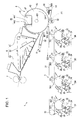
- Figure 1 is a drawing showing an image forming apparatus provided with an embodiment of a transfer device according to the invention
- Figure 2A is a drawing showing the embodiment of the transfer device according to the invention.
- Figure 2B is a drawing showing the embodiment of the transfer device according to the invention.
- Figure 3A to 3D are drawings showing a relationship among a secondary transfer roller, a intermediate transfer belt, and a drive roller;
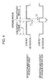
- Figure 4 is a timing chart showing separation and contact actions of a elastic sheet and separation and contact actions of angular contact units
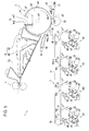
- Figure 5 is a drawing showing an image forming apparatus provided with another embodiment of a transfer device according to the invention.
- Figure 6 is a drawing showing another embodiment of the image forming apparatus provided with the transfer device according to the invention.
- FIG. 1 is a drawing showing an image forming apparatus provided with an embodiment of a transfer device according to the invention.
- An image forming apparatus 1 includes four image forming stations: a yellow image forming station 2Y, a magenta image forming station 2M, a cyan image forming station 2C, and a black image forming station 2K, each of which forms a plurality of images in their respective colors.
- the image forming apparatus 1 is capable of being selectively operated in a color mode in which four colors of toner of yellow (Y), magenta (M), cyan (C), and black (K), are overlapped to form a color image and in a monochrome mode in which only black (K) toner is used to form a monochrome image.
- this image forming apparatus when an image forming command is given to a controller (not shown) having a CPU or a memory from an external device such as a host computer, the controller controls respective portions of the device and performs a predetermined image forming action, whereby an image corresponding to the image forming command is formed on a sheet-shaped recording medium RM such as copy paper, transfer paper, sheet, and OHP transparent sheet.
- a controller not shown
- the controller controls respective portions of the device and performs a predetermined image forming action, whereby an image corresponding to the image forming command is formed on a sheet-shaped recording medium RM such as copy paper, transfer paper, sheet, and OHP transparent sheet.
- the respective image forming stations 2Y, 2M, 2C, and 2K are provided with photoconductor drums 21 on which toner images of the respective colors are formed on the surfaces thereof.
- the respective photoconductor drums 21 are arranged in such a manner that revolving shafts thereof are arranged in parallel to or substantially parallel to a primary scanning direction (the direction vertical to a paper plane of Figure 1 ), and are driven to rotate at a predetermined velocity in the direction indicted by an arrow D21 in Figure 1 .
- a charger 22 such as a corona charger, is configured to charge the surface of the photoconductor drum 21 to a predetermined potential.
- An exposure unit 23 is configured to expose the surface of the photoconductor drum 21 according to an image signal to form an electrostatic latent image.
- a developing unit 24 is also configured to visualize the electrostatic latent image as a toner image.
- a first squeezing portion 25, a second squeezing portion 26, a primary transfer unit configured to primarily transfer the toner image to an intermediate transfer belt 31 of a transfer unit 3, a cleaning unit configured to perform cleaning of the surface of the photoconductor drum 21 after the transfer, and a cleaner blade are also disposed around the photoconductor drum 21 in the recited order along a direction of rotation D21 of the photoconductor drum 21, clockwise in Figure 1 .
- the charger 22 does not come into contact with the surface of the photoconductor drum 21, and a corona charger conventionally used in the related art may be used as the charger 22.
- a corona charger conventionally used in the related art
- a corona charger conventionally used in the related art
- a scorotron charger is used as the corona charger
- a positive wire current is flowed in a charge wire of the scorotron charger, and a DC grid charge bias is applied on a grid.
- the potential of the surface of the photoconductor drum 21 is set to a substantially uniform potential.
- the exposure unit 23 exposes the surface of the photoconductor drum 21 using a light beam according to an image signal supplied from the external device, causing an exposed electrostatic latent image corresponding to the image signal to be formed.
- the exposure unit 23 may be configured to scan a light beam from a semiconductor laser by a polygon mirror or may be composed of line head or the like having light emitting elements arranged in the primary scanning direction.
- Toner is supplied from the developing unit 24 to the exposed electrostatic latent image, and the electrostatic latent image is developed by the toner.
- toner development is performed using liquid developer containing substantially 20% weight ratio of toner dispersed in carrier liquid.
- a high viscosity liquid developer (on the order of 30 to 10000 pa ⁇ s) obtained by adding solid material of about 1 ⁇ m in average particle diameter including a coloring agent such as pigment dispersed to a high concentration and high viscosity resin having non-volatility at room temperatures into a liquid solvent such as organic solvent, silicon oil, mineral oil, or edible oil together with a dispersing agent to have a toner solid content concentration of about 20% is used as the carrier liquid instead of low concentration (1 to 2 wt%) and low viscosity volatile liquid developer having volatility at room temperatures and containing lsoper (Trade Mark: Exxson).
- the first squeezing portion 25 is arranged on the downstream side of a developing position in the direction of rotation D21 of the photoconductor drum 21, and the second squeezing portion 26 is arranged on the downstream side of the first squeezing portion 25.
- Squeeze rollers are provided at these squeezing portions 25 and 26 respectively. The respective squeezing rollers come into contact with the surface of the photoconductor drum 21 to remove excessive carrier liquid or fogged toner of the toner image.
- the number and arrangement of the squeezing portions are not limited thereto and, for example, arrangement of only one squeezing portion may also be used.
- the toner image having passed through the squeezing portions 25 and 26 is primarily transferred to the intermediate transfer belt 31 by the primary transfer unit.
- the intermediate transfer belt 31 is extended between a pair of belt transfer rollers 32 and 33 disposed apart from each other, and is brought into an orbital rotation in a predetermined direction D31 by driving the roller by a belt drive motor. More specifically, the right side roller 32 of these belt transfer rollers 32 and 33 in Figure 1 is a drive roller, and the belt drive motor is mechanically connected to the drive roller 32.
- a driver (not shown) is provided for driving the belt drive motor, which outputs a drive signal according to a command pulse provided from a controller to the belt drive motor and controls the position.
- the drive roller (belt transfer roller) 32 rotates in a direction D32 indicated by the arrow in Figure 1 at a peripheral velocity corresponding to the command pulse, and the surface of the intermediate transfer belt 31 performs an orbital movement in the direction D31 at a constant velocity.
- the drive roller 32 transmits the drive from the belt drive motor to the intermediate transfer belt 31.
- the drive roller 32 comprises a drive transmitting portion as recited in the claims below.
- the primary transfer unit includes a backup roller 271, and the backup roller 271 is disposed so as to oppose the photoconductor drum 21 with the intermediary of the intermediate transfer belt 31 at a primary transfer position TR1, and transfers the toner image on the photoconductor drum 21 to the intermediate transfer belt 31. Then, by performing transfer of the toner images by the respective transfer units 27, the toner images of the respective colors on the photoconductor drums 21 are superimposed on the intermediate transfer belt 31 in sequence, so that a full color toner image is formed.
- the intermediate transfer belt 31 configured as described above comprises the image carrier of the claimed invention.
- the toner image transferred to the intermediate transfer belt 31 is transported to a secondary transfer position TR2 as shown in Figure 1 .
- the transfer device according to the invention is arranged at the secondary transfer position TR2.
- a secondary transfer roller 4 of the transfer device (comprising the transfer portion of the claimed invention) is disposed so as to oppose the drive roller 32 of the transfer unit 3 with the intermediary of the intermediate transfer belt 31 wound around the drive roller 32.
- the secondary transfer position TR2 a single color or a plurality of colors of toner images formed on the intermediate transfer belt 31 are transferred to the recording medium RM transported from a pair of gate rollers 51 and 51 along a transporting path PT.
- the secondary transfer roller 4 having a griping portion is used which will be described more fully below.
- the recording medium RM on which the toner image is secondarily transferred is fed from the secondary transfer roller 4 to a transporting mechanism 6 along the transporting path PT.
- a first sucking portion 61, a transfer material transporting portion 62, and a second sucking portion 63 are arranged in sequence along the transporting path PT, and these members work in association to transport the recording medium RM to a fixing unit 7.
- a blowing unit 8 is arranged so as to oppose the secondary transfer roller 4 between the secondary transfer position TR2 and the first sucking portion 61 in this embodiment.
- the blowing unit 8 blows out air from an opening 83 of a case portion 82 generating in association with the operation of an airflow generating portion 81 in the direction indicated by a hollow arrow, so that air is blown onto a leading end of the recording medium RM as it is released from being gripped by a gripping portion 44 of the secondary transfer roller 4, which is described more fully below. Hence the leading end is pressed away from the secondary transfer roller 4 by a projecting claw (not shown).
- the leading end of the recording medium RM is fed toward the first sucking portion 61. Also, by the air blown onto the recording medium RM, a trailing end of the recording medium RM is prevented from coming into contact with the intermediate transfer belt 31 and hence making the image dirty when the trailing end is discharged from the secondary transfer position TR2. In the case where the recording medium RM has a low elastic restoring force and low elasticity, the blowing of air by the blowing unit 8 may be omitted.
- the fixing unit 7 is disposed on the downstream side of the transporting path PT, that is, on the opposite side of the transporting mechanism 6 from the secondary transfer roller 4, which is shown as the left side in Figure 1 , and heat or pressure is applied on the toner image of monochrome or a plurality of colors transferred to the recording medium RM, whereby fixation of the toner image to the recording medium RM is performed.
- Figures 2A and 2B are drawings showing an embodiment of the transfer device according to the invention.
- Figure 2A is a perspective view showing an entire configuration of the transfer device.
- Figure 2B is a side view showing the shape of an angular contact unit which corresponds to a "contact portion" of the invention.
- Figure 3A is a side view showing a relationship among the secondary transfer roller, the intermediate transfer belt, and the drive roller, in a case where the concaved portion opposes the drive roller.
- Figure 3B is a cross-sectional view taken along the line IIIA-2-IIIA-2 in Figure 3A .
- Figure 3C is a side view of the same in a case where a nipping point is formed
- Figure 3D is a cross-sectional view taken along the line IIIB-2-IIIB-2 in Figure 3C.
- the secondary transfer roller 4 includes a roller base member 42.
- the roller base member 42 is rotatable about an axis of rotation A4 extending in the X direction.
- a concaved portion 41 is provided on the outer circumference of the base member 42.
- the roller base member 42 is arranged in such a manner that the axis of rotation A4 extends in parallel or in substantially parallel to an axis of rotation A32 of the drive roller (belt transfer roller) 32, and side panels 422 and 422 are attached on both ends of a revolving shaft 421.
- the side panels 422 and 422 each comprise a disk-shaped metallic plate having a notched portion 422a formed thereon, and the notched portion 422a has a substantially rectangular shape in side view, as shown in Figures 3A and 3C.
- the notched portions 422a are each attached to the revolving shaft 421 at either end of the base member 42, with a distance which is slightly longer than the width of the intermediate transfer belt 31 being between the them.
- a metallic plate 423 is arranged so as to bridge the span between the peripheral edges of the both side panels 422 over the entire length of the base member 42, and peripheral edge portions of the metallic plate 423 are joined to inner surfaces of the both side panels 422.
- the roller base member 42 having a drum shape as a whole, and including the concaved portion 41 on part of the outer circumference so as to extend in parallel or in substantially parallel to the revolving shaft 421 is formed.
- a elastic sheet 43 such as rubber or resin is formed on the outer circumference of the roller base member 42, that is, on the surface area of the metallic plate except at the area corresponding to the interior of the concaved portion 41.
- the elastic sheet 43 opposes the intermediate transfer belt 31 wound around the drive roller 32, which is described more fully below, and forms a nipping point NP.
- the gripping portion 44 for gripping the recording medium RM is disposed in the interior of the concaved portion 41.
- the gripping portion 44 includes a gripper supporting member 441 provided so as to extend upright from an inner bottom portion of the concaved portion 41 to the outer circumference of the roller base member 42, and a gripper member 442 supported so as to come into and out of contact with the distal end of the gripper supporting member 441.
- the gripper member 442 is connected to the gripper drive portion (not shown).
- the distal end of the gripper member 442 is separated from the distal end of the gripper supporting member 441 gripping the recording medium RM causing the supporting member 441 and the gripper member 442 to release the grip.
- the distal end of the gripper member 442 is moved to the distal end of the gripper supporting member 441, causing the gripper supporting member 441 and the gripper member 442 to grip the recording medium RM.
- the configuration of the gripping portion 44 is not limited to this embodiment and, for example, other gripping mechanisms known in the related art, such as the mechanism disclosed in JP-A-2000-238400 may be employed.
- Supporting members 46 are attached to the outside surfaces of the respective side panels 422 on both sides in a direction of axis of rotation X, that is, at both ends of the revolving shaft 421 so as to be rotatable integrally with the roller base member 42.
- the supporting members 46 each include a planer area 461 corresponding to the concaved portion 41.
- the transfer roller side angular contact units (or contact portions) 47 are attached respectively to the planar areas 461.
- Each angular contact unit 47 is configured in such a manner that a base portion 471 is attached to the supporting member 46, and the portion from the base portion 471 to an angular contact portion 472 extends in the normal direction of the planar area 461, and the distal end of the angular contact portion 472 extends to a position in the vicinity of the end of the concaved portion 41 on the opening side.
- Elastic members 473 are attached to the outer circumference of the distal end of the angular contact portions 472. As shown in Figure 2B , the elastic member 473 is formed so as to have a curvature Rct at the center portion of the outer circumference on the distal end side which is larger than the curvatures Rrs, Rls at the both ends.
- the outer diameter of the roller of the roller base member 42 including the elastic sheet 43 is set to approximately 191 mm, while the curvature Rct is set to 88.2 mm, and the curvatures Rrs and Rls at the both ends are set to 22.4 mm.
- a center of curvature CC at the center portion of the each elastic member 473 is arranged at the axis of rotation of the roller base member 42, that is, the center axis of the revolving shaft 421, and an angular range ⁇ at the center portion is set to be 63° which is slightly wider than the range of opening (60°) of the concaved portion 41.
- a length of the opening (opening width) W41 of the concaved portion 41 along a direction of rotation D4 of the roller base member 42 is: 191 ⁇ ⁇ ⁇ 60 / 360 ⁇ 100 mm .
- a length of the nipping point NP (nip width) Wnp along the direction of rotation D4 of the roller base member 42 is on the order of 11 mm, and has a relation: opening width W ⁇ 41 of concaved portion 41 > nip width Wnp at nip NP .
- the secondary transfer roller 4 configured in this manner is arranged such that the revolving shaft 421 extends in parallel or in substantially parallel to the axis of rotation A32 of the drive roller 32, and is urged toward the drive roller 32 side by a pressing portion, not shown. Therefore, in the angular range ⁇ , 300° in this embodiment, as shown in Figures 3C and 3D, the elastic sheet 43 is pressed against the intermediate transfer belt 31 wound around the drive roller 32 and the nipping point NP is formed.
- annular angular contact members 322 are attached to the both ends of a revolving shaft 321 of the drive roller 32, and the outer diameter is set to be larger than the value of [(thickness of intermediate transfer belt 31) ⁇ 2 + (outer diameter of drive roller 32)]. Therefore, in the angular range ⁇ , as shown in Figures 3A and 3B , the center portions of the elastic members 473 of the angular contact units 47 on the transfer roller side come into contact with the drive roller side angular contact members 322, which correspond to "supporting portion" of the invention, and come into contact with the drive roller 32 via the drive roller side angular contact members 322.
- a relationship of: ⁇ + ⁇ > 360 ⁇ ° is established as described above, and the transfer device is configured in such a manner that the angular ranges ⁇ , ⁇ overlap with each other as described below.
- Figure 4 is a timing chart showing separation and contact actions of a elastic sheet and separation and contact actions of an angular contact unit.
- the period in which the concaved portion 41 opposes the intermediate transfer belt 31, referred to as an opposed period, and the period in which it does not oppose the intermediate transfer belt 31, referred to as a non-opposed period, are switched alternately, and the elastic sheet 43 repeats separation and contact with the intermediate transfer belt 31.
- the elastic sheet 43 comes into contact with the intermediate transfer belt 31 to form the nipping point NP, so that the secondary transfer is enabled. Then, the elastic sheet 43 starts to separate from the intermediate transfer belt 31 by the rotation of the secondary transfer roller 4.
- the elastic members 473 of the transfer roller side angular contact units 47 start to come into contact with the drive roller side angular contact members 322 at time T1 before the start of the separation of the elastic sheet 43. Then, when time T1 is elapsed, the concaved portion 41 starts to oppose the intermediate transfer belt 31.
- the secondary transfer roller 4 rotates in a state in which the concaved portion 41 opposes the intermediate transfer belt 31, and the distal end of the gripper member 442 moves to the distal end of the gripper supporting member 441 and grips the recording medium RM at the same time or a bit later than the time when the secondary transfer roller 4 reaches a recording medium gripping position where the gripping portion 44 can grip the recording medium RM transported from the gate rollers 51 and 51. Then, the secondary transfer roller 4 rotates in the direction of rotation D4 while the gripping portion 44 grips the leading end of the recording medium RM.
- the concaved portion 41 starts to be separated from the intermediate transfer belt 31, and the elastic sheet 43 comes into contact with the intermediate transfer belt 31 to form the nipping point NP.
- the elastic members 473 of the transfer roller side angular contact units 47 start to be separated from the drive roller side angular contact members 322.
- the period in which the concaved portion 41 opposes the intermediate transfer belt 31 in the opposed period and the period in which the same does not oppose the intermediate transfer belt 31 in the non-opposed period are alternated, and the elastic sheet 43 comes into contact with the intermediate transfer belt 31 and the elastic members 473 of the angular contact units 47 come into contact with the drive roller 32 via the drive roller side angular contact member 322 at the time T1 when the non-opposed period is switched to the opposed period and for the time T2 when the opposed period is switched to the non-opposed period.
- the overlapping mode is not limited thereto as a matter of course, and overlapping may be set to only when the non-opposed period is switched to the opposed period or, in contrast, only when the opposed period is switched to the non-opposed period.
- the transfer roller side angular contact units 47 come into contact with the drive roller 32 via the drive roller side angular contact members 322
- a configuration where the transfer roller side angular contact units 47 come into direct contact with the drive roller 32 is also applicable.
- a transfer roller drive motor (not shown) is mechanically connected to the revolving shaft 421 of the secondary transfer roller 4.
- a driver (not shown) is provided so as to drive the transfer roller drive motor, and the motor is driven according to the command given from the controller to drive the secondary transfer roller 4 to rotate clockwise in the paper plane of Figure 1 , that is, in a widthwise direction D4 with respect to the drive roller 32.
- the transfer device includes the secondary transfer roller 4, the pressing portion, and the angular contact units 47, and the image carried by the intermediate transfer belt 31 is secondarily transferred to the recording medium RM by the transfer device.
- the elastic sheet 43 of the secondary transfer roller 4 is separated from the intermediate transfer belt 31 and hence the load applied to the intermediate transfer belt 31 is eliminated during the opposed period in which the concaved portion 41 opposes the intermediate transfer belt 31.
- the load is replaced by the elastic members 473 provided on the outer circumference of the angular contact units 47 coming into contact with the drive roller 32 for driving the intermediate transfer belt 31.
- the difference between the load applied on the intermediate transfer belt 31 during the opposed period and the load applied on the intermediate transfer belt 31 during the non-opposed period may be restrained.
- vibrations in association with the switching may also be restrained.
- the switching is achieved desirably while restraining the load variations, and by using the image forming apparatus provided with the transfer device, high-quality images can be formed.
- the width of the each angular contact unit 47 in the direction of axis of rotation X is significantly restrained in comparison with the width of the secondary transfer roller 4 in the same direction X, and hence downsizing of the device is achieved.
- the contact area of the each elastic member 473 with respect to the drive roller 32 is dramatically smaller than the contact area of the elastic sheet 43 with respect to the intermediate transfer belt 31.
- the load applied on the intermediate transfer belt 31 during the opposed period (the period when the transfer is not performed) is smaller than the load applied on the intermediate transfer belt 31 during the non-opposed period (the period when the transfer is performed). Therefore, in order to reduce the difference of the load, the following configuration is effective.
- the material of the elastic members 473 is selected so that the hardness of the elastic members 473 exceeds the hardness of the elastic sheet 43.
- the transfer device of this type a rubber sheet or a resin sheet having a hardness of 40° to 60° according to Japanese Industrial Standards "JIS K 6253" is used as the elastic sheet 43 in many cases and, in this embodiment, a rubber sheet having a hardness of 60° is employed. Therefore, in this embodiment, the elastic members 473 are formed of a elastic material having a harness of 80° according to "JIS K 6253".
- the elastic member 473 and the elastic sheet 43 can be configured so that the coefficient of friction of the elastic member 473 exceeds the coefficient of friction of the elastic sheet 43.
- the frictional force generated when the elastic member 473 comes into contact with the drive roller side angular contact member 322 exceeds the frictional force generated when the elastic sheet 43 comes into contact with the intermediate transfer belt 31. Consequently, the difference of the load is reduced, and the load variations can be restrained further effectively.
- the front layer of the elastic sheet 43 of a material containing fluorine contained resin such as PTFE (polytetrafluoroethylene) mixed in urethane rubber, and on the other hand, to increase the coefficient of friction by forming the elastic members 473 of urethane rubber which is not mixed with fluorine contained resin. It is also possible to form the elastic members 473 of urethane rubber containing fluorine contained resin mixed therein as a matter of course and, in this case, the ratio of mixture of the fluorine contained resin in the elastic sheet 43 is preferably higher than that of the elastic members 473.
- PTFE polytetrafluoroethylene
- the elastic members 473 are formed with a larger thickness than the elastic sheet 43, the difference of the load is reduced in the same manner as the above-described embodiment, and the load variations can be restrained further effectively.
- the annular angular contact member 322 is fixed to the revolving shaft 321 of the drive roller 32 so as to allow the elastic members 473 of the transfer roller side angular contact units 47 to come into contact with the angular contact members 322.
- the difference of the load becomes smaller in the same reason, so that the load variations can be restrained even more effectively.
- the object of application of the invention is not limited to the above-described embodiment and, for example, the invention is also applicable to a transfer device configured to form a wound nipping point, as shown in Figure 5 , in order to transfer the image carried by the intermediate transfer belt 31 to the recording medium RM.
- this may be embodied in an image forming apparatus having such transfer device.
- the intermediate transfer belt 31 is wound around the drive roller 32, a first tension roller 33, a second tension roller 35, and a third tension roller 36, and is driven by the drive roller 32 to rotate in a state of being in contact with the photoconductor drum 21 at the primary transfer positions TR1 of the respective colors.
- toner images formed at the respective image forming stations 2Y, 2M, 2C, and 2K are transferred onto the intermediate transfer belt 31 by superimposing in sequence, so that a full color toner image is formed.
- the secondary transfer roller 4 is arranged so as to oppose the drive roller 32 with the intermediary of the intermediate transfer belt 31, and the elastic sheet 43 opposes the intermediate transfer belt 31 to form the nipping point NP.
- the secondary transfer position TR2 where the nipping point NP is formed a single color or a plurality of colors of toner images carried by the intermediate transfer belt 31 are transferred to the recording medium RM transported from the pair of gate rollers 51 along the transporting path PT.
- the invention is applied to the transfer device configured to transfer the image carried by the intermediate transfer belt 31 to the recording medium RM.
- the invention may be applied to the transfer device configured to transfer the image carried by a transfer drum to the recording medium RM as shown in Figure 6 and the image forming apparatus having such transfer device.
- FIG. 6 is a drawing showing another embodiment of the image forming apparatus provided with the transfer device according to the invention.
- the transfer unit 3 includes three intermediate transfer drums 37A, 37B, and 37C.
- the image forming stations 2Y and 2M are arranged in this order along a direction of rotation Da of the intermediate transfer drum 37A, and toner images formed in the respective image forming stations 2Y and 2M are transferred so as to be overlapped in sequence on the intermediate transfer drum 37A, so that a toner image of two colors, such as yellow and magenta, is formed.
- the intermediate transfer drum 37B is arranged apart from the intermediate transfer drum 37A in the horizontal direction (the lateral direction in Figure 6 ).
- the image forming stations 2C and 2K are arranged in this order along a direction of rotation Db of the intermediate transfer drum 37B, and toner images formed in the respective image forming stations 2C and 2K are transferred so as to overlap in sequence on the intermediate drum 38B, so that a toner image of two colors, such as cyan and black, is formed. Furthermore, the remaining intermediate transfer drum 37C is arranged above the intermediate transfer drums 37A and 378 so as to be capable of coming into sliding contact with the respective outer circumferences, and two-color toner images carried by the respective intermediate transfer drums 37A and 37B are transferred onto the intermediate transfer drum 37C so as to be overlapped in sequence. Accordingly, a full color toner image is carried on the intermediate transfer drum 37C.
- a transfer device having the same configuration as in the embodiments described above is arranged so as to oppose the intermediate transfer drum 37C.
- the transfer device includes the secondary transfer roller 4, the pressing portion (not shown), and the angular contact units 47, and secondarily transfers the image carried by the intermediate transfer drum 37C to the recording medium RM.
- the elastic sheet 43 of the secondary transfer roller 4 is separated from the intermediate transfer drum 37C and the load to the intermediate transfer drum 37C is eliminated during the opposed period in which the concaved portion 41 opposes the intermediate transfer drum 37C.
- the load is replaced by the elastic members 473 (see Figures 2A and 2B ) provided on the outer circumferences of the angular contact units 47 coming into contact with the driving portion such as the revolving shaft of the intermediate transfer drum 37C or the like, which result in another load being applied on the intermediate transfer drum 37C. Therefore, the difference between the load applied on the intermediate transfer drum 37C during the opposed period and the load applied on the intermediate transfer drum 37C during the non-opposed period may be restrained. In addition, since an impact at the time of switching between the opposed period and the non-opposed period is absorbed by a elastic force of the elastic members 473, vibrations in association with the switching may also be restrained. In this manner, according to this embodiment, the switching is achieved desirably while restraining the load variations, and by using the image forming apparatus provided with the transfer device, high-quality images can be formed.
- the invention is applied to the transfer device configured to secondarily transfer the toner images carried by the intermediate transfer belt 31 or the intermediate transfer drum 37C to the recording medium RM as described above, the invention may be preferably applied to the transfer device configured to transfer the toner images formed on photoconductor members to a recording medium or an image forming apparatus provided with such transfer device.
Landscapes
- Physics & Mathematics (AREA)
- General Physics & Mathematics (AREA)
- Electrostatic Charge, Transfer And Separation In Electrography (AREA)
Abstract
Description
- The entire disclosures of Japanese Patent Application No.
2009-133265, filed June 2, 2009 - The present invention relates to a transfer device configured to transfer an image formed on an image carrier to a recording medium and an image forming apparatus provided with the device.
- Image forming apparatuses which develop and form electrostatic latent images using a high-viscosity liquid developer including toner formed of solid component dispersed in carrier liquid, are currently known in the art. One example of one of these image forming apparatuses is in
Figure 1 of Japanese Patent Document No.JP-A-2009-14808 - In the '808 image forming apparatus, four image forming stations configured to form images of different colors are provided and are used to form toner images which are superimposed on an intermediate transfer belt, thereby forming a multi-color image on the intermediate transfer belt. The intermediate transfer belt is extended between a pair of drive roller and a driven roller which are disposed apart from each other. The intermediate transfer belt is rotated in a predetermined direction while carrying the color image by driving the drive roller using a belt drive motor. A transfer device often used in a so-called dry image forming apparatus is provided so as to oppose the drive roller, and the color image is secondarily transferred to the recording medium, which may comprise a variety of different types of media, including as sheets of paper, films, cloths, and so on. In other words, a secondary transfer roller covered with a elastic member such as rubber over an outer circumference thereof is disposed at a secondary transfer position so as to oppose the drive roller with the intermediate transfer belt being disposed between the secondary transfer roller and the drive roller, thereby forming a nipping area with respect to the intermediate transfer belt.
- Then, by driving the drive roller using the belt drive motor, the intermediate transfer belt is rotated by the intermediate transfer belt and the secondary transfer roller is driven and rotated, causing the recording medium to be pinched and transported at the nipping area. During the transportation in the nipping point, the color image formed on the intermediate transfer belt is secondarily transferred to the recording medium.
- Additional examples of apparatuses known in the art are illustrated in
Figure 1 ofJP-A-2009-14808 Figure 1 ofJP-A-2000-238400 - Since the apparatus disclosed in
JP-A-2009-14808 - More particularly, in the stencil printing apparatus, such as the apparatus described in
JP-A-2000-238400 - Thus, using the sheet clamper, the printed sheet is not stuck to the cylinder and is reliably separated from the cylinder on the downstream side of the pressed position even though high-viscosity ink is used. Because this system works reliably for an stencil printing apparatus, attempts have been made to configure the secondary transfer roller in the same manner as the impression cylinder, that is, to provide the secondary transfer roller with a gripping portion which may be used to grip the recording medium on the secondary transfer roller. In other words, by driving the secondary transfer roller while gripping the leading end (non-image portion) of the recording medium with the gripping portion, the recording medium having passed through the nipping point is separated desirably from the intermediate transfer belt, and paper jams can be effectively prevented.
- However, when diverting the transfer device disclosed in
JP-A-2000-238400 JP-A-2000-238400 - The second point is that it is necessary to provide a concaved portion on the outer periphery of the secondary transfer roller and dispose the gripping portion in the concaved portion. In other words, while the concaved portion opposes the intermediate transfer belt, the recording medium is needed to be gripped in a state in which the outer circumference of the secondary transfer roller is kept separate from the surface of the intermediate transfer belt.
- Then, when the concaved portion does not oppose the intermediate transfer belt, that is, when the outer circumference of the secondary transfer roller opposes the surface of the intermediate transfer belt and forms the nipping point, the toner image carried on the intermediate transfer belt is transferred to the recording medium.
- In this manner, although a period in which the outer periphery of the secondary transfer roller opposes the intermediate transfer belt (contact period) and a period in which they are separated (separation period) are mixed while the secondary transfer roller makes one turn, the secondary transfer roller is pressed toward the intermediate transfer belt. Therefore, the load applied on the intermediate transfer belt may vary significantly when the contact period is switched to the separation period or vice versa. In particular, in the stencil printing apparatus disclosed in
JP-A-2000-238400 - As a consequence of the load variations which may occur during the image forming processes, problems such as fluctuations in the latent image at the latent image forming position (exposing portion) or fluctuations in the primarily transferred toner image. These fluctuations may lower the image quality.
- An advantage of some aspects of the invention is to provide a transfer device configured to transfer an image carried on an image carrier to a recording medium using a transfer roller having a concaved portion on the outer circumference thereof and an image forming apparatus provided with the device capable of restraining load variations generated at the time of transfer.
A first aspect of the invention is a transfer device including a transfer roller including a roller base member opposing an image carrier for carrying an image which rotating about an axis of rotation, having a concaved portion on an outer circumference thereof, and being configured to transfer the image carried by the image carrier to a recording medium while the concaved portion does not oppose the image carrier, a pressing portion configured to press the transfer roller to the image carrier, a supporting portion disposed on a drive transmitting portion configured to transmit a drive to the image carrier when the concaved portion opposes the image carrier, and a contact portion provided at end of the roller base member in the direction of the axis of rotation at a position corresponding to the concaved portion, the contact portion including an outer circumference which comes into contact with the supporting portion, the outer circumference of the contact member also having a elastic member formed therein. - Another aspect of the invention is an image forming apparatus including an image forming portion configured to form an image, an image carrier configured to carry the image formed by the image forming portion, a driving portion configured to drive the image carrier, a drive transmitting portion configured to transmit a drive from the driving portion, a supporting portion disposed on the drive transmitting portion, and a transfer portion configured to transfer the image carried by the image carrier to a recording medium, wherein the transfer portion includes: a transfer roller including a roller base member opposing the image carrier, rotating about an axis of rotation, and having a concaved portion on an outer circumference thereof, and being configured to perform the transfer while the concaved portion does not oppose the image carrier, a pressing portion configured to press the transfer roller to the image carrier, and a contact portion provided at a position corresponding to the concaved portion in the direction of the revolving shaft, the contact portion includes an outer circumference which comes into contact with a supporting portion while the concaved portion opposes the image carrier, and a elastic member is provided on the outer circumference of the contact portion.
- In the transfer device and the image forming apparatus described above, the transfer roller rotates about the revolving shaft while being pressed by the pressing portion against the image carrier, and the period in which the concaved portion opposes the image carrier, referred to as the opposed period, and the period in which the same is not opposed, referred to as the non-opposed period are switched alternately. In the non-opposed period in which the concaved portion does not oppose the image carrier, the outer circumference of the transfer roller opposes the image carrier and a nipping point is formed between the transfer roller and the image carrier. Then, by causing the recording medium to pass through the nipping point, the image carried by the image carrier is transferred to the recording medium. In this manner, a predetermined load is applied on the image carrier in this period. In contrast, in the opposed period in which the concaved portion opposes the image carrier, the outer circumference of the transfer roller is separated from the image carrier, and the load is eliminated, but a elastic member provided on the outer circumference of the contact portion comes into contact with the supporting portion disposed on the drive transmitting portion which transmits the drive to the image carrier, whereby another load is applied on the image carrier. Therefore, the difference between the load applied on the image carrier during the opposed period and the load applied on the image carrier during the non-opposed period may be restrained. In addition, an impact at the time of switching between the opposed period and the non-opposed period is absorbed by a elastic force of the elastic member. In this manner, the switching is desirably achieved while restraining the load variations.
- The invention will be described with reference to the accompanying drawings where like numbers reference like elements.
-
Figure 1 is a drawing showing an image forming apparatus provided with an embodiment of a transfer device according to the invention; -
Figure 2A is a drawing showing the embodiment of the transfer device according to the invention; -
Figure 2B is a drawing showing the embodiment of the transfer device according to the invention; -
Figure 3A to 3D are drawings showing a relationship among a secondary transfer roller, a intermediate transfer belt, and a drive roller; -
Figure 4 is a timing chart showing separation and contact actions of a elastic sheet and separation and contact actions of angular contact units; -
Figure 5 is a drawing showing an image forming apparatus provided with another embodiment of a transfer device according to the invention; and -
Figure 6 is a drawing showing another embodiment of the image forming apparatus provided with the transfer device according to the invention. -
Figure 1 is a drawing showing an image forming apparatus provided with an embodiment of a transfer device according to the invention. Animage forming apparatus 1 includes four image forming stations: a yellowimage forming station 2Y, a magentaimage forming station 2M, a cyanimage forming station 2C, and a blackimage forming station 2K, each of which forms a plurality of images in their respective colors. Theimage forming apparatus 1 is capable of being selectively operated in a color mode in which four colors of toner of yellow (Y), magenta (M), cyan (C), and black (K), are overlapped to form a color image and in a monochrome mode in which only black (K) toner is used to form a monochrome image. In this image forming apparatus, when an image forming command is given to a controller (not shown) having a CPU or a memory from an external device such as a host computer, the controller controls respective portions of the device and performs a predetermined image forming action, whereby an image corresponding to the image forming command is formed on a sheet-shaped recording medium RM such as copy paper, transfer paper, sheet, and OHP transparent sheet. - The respective
image forming stations photoconductor drums 21 on which toner images of the respective colors are formed on the surfaces thereof. The respective photoconductor drums 21 are arranged in such a manner that revolving shafts thereof are arranged in parallel to or substantially parallel to a primary scanning direction (the direction vertical to a paper plane ofFigure 1 ), and are driven to rotate at a predetermined velocity in the direction indicted by an arrow D21 inFigure 1 . - Around the each
photoconductor drum 21, acharger 22, such as a corona charger, is configured to charge the surface of thephotoconductor drum 21 to a predetermined potential. Anexposure unit 23 is configured to expose the surface of thephotoconductor drum 21 according to an image signal to form an electrostatic latent image. A developingunit 24 is also configured to visualize the electrostatic latent image as a toner image. In addition to these components, a first squeezingportion 25, a second squeezingportion 26, a primary transfer unit configured to primarily transfer the toner image to anintermediate transfer belt 31 of atransfer unit 3, a cleaning unit configured to perform cleaning of the surface of thephotoconductor drum 21 after the transfer, and a cleaner blade are also disposed around thephotoconductor drum 21 in the recited order along a direction of rotation D21 of thephotoconductor drum 21, clockwise inFigure 1 . - The
charger 22 does not come into contact with the surface of thephotoconductor drum 21, and a corona charger conventionally used in the related art may be used as thecharger 22. When a scorotron charger is used as the corona charger, a positive wire current is flowed in a charge wire of the scorotron charger, and a DC grid charge bias is applied on a grid. By thephotoconductor drum 21 charged with corona discharge by thecharger 22, the potential of the surface of thephotoconductor drum 21 is set to a substantially uniform potential. - The
exposure unit 23 exposes the surface of thephotoconductor drum 21 using a light beam according to an image signal supplied from the external device, causing an exposed electrostatic latent image corresponding to the image signal to be formed. Theexposure unit 23 may be configured to scan a light beam from a semiconductor laser by a polygon mirror or may be composed of line head or the like having light emitting elements arranged in the primary scanning direction. - Toner is supplied from the developing
unit 24 to the exposed electrostatic latent image, and the electrostatic latent image is developed by the toner. In the developingunit 24 of theimage forming apparatus 1, toner development is performed using liquid developer containing substantially 20% weight ratio of toner dispersed in carrier liquid. In this embodiment, a high viscosity liquid developer (on the order of 30 to 10000 pa·s) obtained by adding solid material of about 1 µm in average particle diameter including a coloring agent such as pigment dispersed to a high concentration and high viscosity resin having non-volatility at room temperatures into a liquid solvent such as organic solvent, silicon oil, mineral oil, or edible oil together with a dispersing agent to have a toner solid content concentration of about 20% is used as the carrier liquid instead of low concentration (1 to 2 wt%) and low viscosity volatile liquid developer having volatility at room temperatures and containing lsoper (Trade Mark: Exxson). - The first squeezing
portion 25 is arranged on the downstream side of a developing position in the direction of rotation D21 of thephotoconductor drum 21, and the second squeezingportion 26 is arranged on the downstream side of the first squeezingportion 25. Squeeze rollers are provided at these squeezingportions photoconductor drum 21 to remove excessive carrier liquid or fogged toner of the toner image. Although the excessive carrier liquid and fogged toner are removed by the two squeezingportions - The toner image having passed through the squeezing
portions intermediate transfer belt 31 by the primary transfer unit. Theintermediate transfer belt 31 is extended between a pair ofbelt transfer rollers right side roller 32 of thesebelt transfer rollers Figure 1 is a drive roller, and the belt drive motor is mechanically connected to thedrive roller 32. - In this embodiment, a driver (not shown) is provided for driving the belt drive motor, which outputs a drive signal according to a command pulse provided from a controller to the belt drive motor and controls the position. Accordingly, the drive roller (belt transfer roller) 32 rotates in a direction D32 indicated by the arrow in
Figure 1 at a peripheral velocity corresponding to the command pulse, and the surface of theintermediate transfer belt 31 performs an orbital movement in the direction D31 at a constant velocity. In this manner, in this embodiment, thedrive roller 32 transmits the drive from the belt drive motor to theintermediate transfer belt 31. As such, thedrive roller 32 comprises a drive transmitting portion as recited in the claims below. - The primary transfer unit includes a
backup roller 271, and thebackup roller 271 is disposed so as to oppose thephotoconductor drum 21 with the intermediary of theintermediate transfer belt 31 at a primary transfer position TR1, and transfers the toner image on thephotoconductor drum 21 to theintermediate transfer belt 31. Then, by performing transfer of the toner images by the respective transfer units 27, the toner images of the respective colors on the photoconductor drums 21 are superimposed on theintermediate transfer belt 31 in sequence, so that a full color toner image is formed. In this manner, in this embodiment, theintermediate transfer belt 31 configured as described above comprises the image carrier of the claimed invention. - The toner image transferred to the
intermediate transfer belt 31 is transported to a secondary transfer position TR2 as shown inFigure 1 . The transfer device according to the invention is arranged at the secondary transfer position TR2. In other words, asecondary transfer roller 4 of the transfer device (comprising the transfer portion of the claimed invention) is disposed so as to oppose thedrive roller 32 of thetransfer unit 3 with the intermediary of theintermediate transfer belt 31 wound around thedrive roller 32. - Then, at the secondary transfer position TR2, a single color or a plurality of colors of toner images formed on the
intermediate transfer belt 31 are transferred to the recording medium RM transported from a pair ofgate rollers secondary transfer roller 4 having a griping portion is used which will be described more fully below. - The recording medium RM on which the toner image is secondarily transferred is fed from the
secondary transfer roller 4 to a transportingmechanism 6 along the transporting path PT. In the transportingmechanism 6, a first suckingportion 61, a transfermaterial transporting portion 62, and a second suckingportion 63 are arranged in sequence along the transporting path PT, and these members work in association to transport the recording medium RM to afixing unit 7. - When the recording medium RM having the toner image secondarily transferred thereto is sent to the transporting
mechanism 6, in order to ensure feeding of the recording medium RM to the first suckingportion 61 and prevent the image from becoming dirty, ablowing unit 8 is arranged so as to oppose thesecondary transfer roller 4 between the secondary transfer position TR2 and the first suckingportion 61 in this embodiment. Theblowing unit 8 blows out air from anopening 83 of acase portion 82 generating in association with the operation of anairflow generating portion 81 in the direction indicated by a hollow arrow, so that air is blown onto a leading end of the recording medium RM as it is released from being gripped by a grippingportion 44 of thesecondary transfer roller 4, which is described more fully below. Hence the leading end is pressed away from thesecondary transfer roller 4 by a projecting claw (not shown). - In this manner, the leading end of the recording medium RM is fed toward the first sucking
portion 61. Also, by the air blown onto the recording medium RM, a trailing end of the recording medium RM is prevented from coming into contact with theintermediate transfer belt 31 and hence making the image dirty when the trailing end is discharged from the secondary transfer position TR2. In the case where the recording medium RM has a low elastic restoring force and low elasticity, the blowing of air by theblowing unit 8 may be omitted. - Furthermore, the fixing
unit 7 is disposed on the downstream side of the transporting path PT, that is, on the opposite side of the transportingmechanism 6 from thesecondary transfer roller 4, which is shown as the left side inFigure 1 , and heat or pressure is applied on the toner image of monochrome or a plurality of colors transferred to the recording medium RM, whereby fixation of the toner image to the recording medium RM is performed. -
Figures 2A and 2B are drawings showing an embodiment of the transfer device according to the invention.Figure 2A is a perspective view showing an entire configuration of the transfer device.Figure 2B is a side view showing the shape of an angular contact unit which corresponds to a "contact portion" of the invention.Figure 3A is a side view showing a relationship among the secondary transfer roller, the intermediate transfer belt, and the drive roller, in a case where the concaved portion opposes the drive roller.Figure 3B is a cross-sectional view taken along the line IIIA-2-IIIA-2 inFigure 3A . Figure 3C is a side view of the same in a case where a nipping point is formed, and Figure 3D is a cross-sectional view taken along the line IIIB-2-IIIB-2 in Figure 3C. - As shown in these drawings, the
secondary transfer roller 4 includes aroller base member 42. Theroller base member 42 is rotatable about an axis of rotation A4 extending in the X direction. Aconcaved portion 41 is provided on the outer circumference of thebase member 42.
As shown inFigures 3A-3D , theroller base member 42 is arranged in such a manner that the axis of rotation A4 extends in parallel or in substantially parallel to an axis of rotation A32 of the drive roller (belt transfer roller) 32, andside panels shaft 421. More specifically, theside panels portion 422a formed thereon, and the notchedportion 422a has a substantially rectangular shape in side view, as shown inFigures 3A and 3C. Then, as shown inFigures 2A and 2B , the notchedportions 422a are each attached to the revolvingshaft 421 at either end of thebase member 42, with a distance which is slightly longer than the width of theintermediate transfer belt 31 being between the them. Ametallic plate 423 is arranged so as to bridge the span between the peripheral edges of the bothside panels 422 over the entire length of thebase member 42, and peripheral edge portions of themetallic plate 423 are joined to inner surfaces of the bothside panels 422. In this manner, theroller base member 42 having a drum shape as a whole, and including the concavedportion 41 on part of the outer circumference so as to extend in parallel or in substantially parallel to the revolvingshaft 421 is formed. - In addition, a
elastic sheet 43 such as rubber or resin is formed on the outer circumference of theroller base member 42, that is, on the surface area of the metallic plate except at the area corresponding to the interior of theconcaved portion 41. Theelastic sheet 43 opposes theintermediate transfer belt 31 wound around thedrive roller 32, which is described more fully below, and forms a nipping point NP. - The gripping
portion 44 for gripping the recording medium RM is disposed in the interior of theconcaved portion 41. The grippingportion 44 includes agripper supporting member 441 provided so as to extend upright from an inner bottom portion of theconcaved portion 41 to the outer circumference of theroller base member 42, and agripper member 442 supported so as to come into and out of contact with the distal end of thegripper supporting member 441. Thegripper member 442 is connected to the gripper drive portion (not shown). Then, by the operation of the gripper drive portion upon receipt of an release command from the controller, the distal end of thegripper member 442 is separated from the distal end of thegripper supporting member 441 gripping the recording medium RM causing the supportingmember 441 and thegripper member 442 to release the grip. In contrast, by the operation of the gripper drive portion upon receipt of the grip command from the controller, the distal end of thegripper member 442 is moved to the distal end of thegripper supporting member 441, causing thegripper supporting member 441 and thegripper member 442 to grip the recording medium RM. The configuration of the grippingportion 44 is not limited to this embodiment and, for example, other gripping mechanisms known in the related art, such as the mechanism disclosed inJP-A-2000-238400 - Supporting
members 46 are attached to the outside surfaces of therespective side panels 422 on both sides in a direction of axis of rotation X, that is, at both ends of the revolvingshaft 421 so as to be rotatable integrally with theroller base member 42. The supportingmembers 46 each include a planer area 461 corresponding to theconcaved portion 41. Then, the transfer roller side angular contact units (or contact portions) 47 are attached respectively to the planar areas 461. Eachangular contact unit 47 is configured in such a manner that abase portion 471 is attached to the supportingmember 46, and the portion from thebase portion 471 to anangular contact portion 472 extends in the normal direction of the planar area 461, and the distal end of theangular contact portion 472 extends to a position in the vicinity of the end of theconcaved portion 41 on the opening side. - In other words, as shown in
Figure 2A , when viewing theroller base member 42 from the end of the revolvingshaft 421, theangular contact units 47 are arranged so as to close theconcaved portion 41. -
Elastic members 473 are attached to the outer circumference of the distal end of theangular contact portions 472. As shown inFigure 2B , theelastic member 473 is formed so as to have a curvature Rct at the center portion of the outer circumference on the distal end side which is larger than the curvatures Rrs, Rls at the both ends. For example, in this embodiment, the outer diameter of the roller of theroller base member 42 including theelastic sheet 43 is set to approximately 191 mm, while the curvature Rct is set to 88.2 mm, and the curvatures Rrs and Rls at the both ends are set to 22.4 mm. A center of curvature CC at the center portion of the eachelastic member 473 is arranged at the axis of rotation of theroller base member 42, that is, the center axis of the revolvingshaft 421, and an angular range α at the center portion is set to be 63° which is slightly wider than the range of opening (60°) of theconcaved portion 41. - Therefore, as described later, when the
secondary transfer roller 4 is rotated, theconcaved portion 41 opposes theintermediate transfer belt 31 wound around thedrive roller 32 across the angular range α. Also, a length of the opening (opening width) W41 of theconcaved portion 41 along a direction of rotation D4 of theroller base member 42 is:
In contrast, in an angular range β (= 360° - 60°), theelastic sheet 43 opposes theintermediate transfer belt 31 to form the nipping point NP as described below, and the length of theelastic sheet 43 along the direction of rotation D4 of theroller base member 42 is set to:
In this embodiment, a length of the nipping point NP (nip width) Wnp along the direction of rotation D4 of theroller base member 42 is on the order of 11 mm, and has a relation:
- The
secondary transfer roller 4 configured in this manner is arranged such that the revolvingshaft 421 extends in parallel or in substantially parallel to the axis of rotation A32 of thedrive roller 32, and is urged toward thedrive roller 32 side by a pressing portion, not shown. Therefore, in the angular range β, 300° in this embodiment, as shown in Figures 3C and 3D, theelastic sheet 43 is pressed against theintermediate transfer belt 31 wound around thedrive roller 32 and the nipping point NP is formed. In this embodiment, annularangular contact members 322 are attached to the both ends of a revolving shaft 321 of thedrive roller 32, and the outer diameter is set to be larger than the value of [(thickness of intermediate transfer belt 31) × 2 + (outer diameter of drive roller 32)]. Therefore, in the angular range α, as shown inFigures 3A and 3B , the center portions of theelastic members 473 of theangular contact units 47 on the transfer roller side come into contact with the drive roller sideangular contact members 322, which correspond to "supporting portion" of the invention, and come into contact with thedrive roller 32 via the drive roller sideangular contact members 322. However, in the embodiment, a relationship of:
is established as described above, and the transfer device is configured in such a manner that the angular ranges α, β overlap with each other as described below. -
Figure 4 is a timing chart showing separation and contact actions of a elastic sheet and separation and contact actions of an angular contact unit. In this embodiment, as shown inFigure 4 , the period in which theconcaved portion 41 opposes theintermediate transfer belt 31, referred to as an opposed period, and the period in which it does not oppose theintermediate transfer belt 31, referred to as a non-opposed period, are switched alternately, and theelastic sheet 43 repeats separation and contact with theintermediate transfer belt 31. - In other words, while the
concaved portion 41 is away from theintermediate transfer belt 31 in the non-opposed period, theelastic sheet 43 comes into contact with theintermediate transfer belt 31 to form the nipping point NP, so that the secondary transfer is enabled. Then, theelastic sheet 43 starts to separate from theintermediate transfer belt 31 by the rotation of thesecondary transfer roller 4. In this embodiment, theelastic members 473 of the transfer roller sideangular contact units 47 start to come into contact with the drive roller sideangular contact members 322 at time T1 before the start of the separation of theelastic sheet 43. Then, when time T1 is elapsed, theconcaved portion 41 starts to oppose theintermediate transfer belt 31. - The
secondary transfer roller 4 rotates in a state in which theconcaved portion 41 opposes theintermediate transfer belt 31, and the distal end of thegripper member 442 moves to the distal end of thegripper supporting member 441 and grips the recording medium RM at the same time or a bit later than the time when thesecondary transfer roller 4 reaches a recording medium gripping position where the grippingportion 44 can grip the recording medium RM transported from thegate rollers secondary transfer roller 4 rotates in the direction of rotation D4 while the grippingportion 44 grips the leading end of the recording medium RM. Then, when thesecondary transfer roller 4 rotates a predetermined angle from the recording medium gripping position, theconcaved portion 41 starts to be separated from theintermediate transfer belt 31, and theelastic sheet 43 comes into contact with theintermediate transfer belt 31 to form the nipping point NP. After time T2 has elapsed from the contact of theelastic sheet 43, theelastic members 473 of the transfer roller sideangular contact units 47 start to be separated from the drive roller sideangular contact members 322. - As described above, in this embodiment, the period in which the
concaved portion 41 opposes theintermediate transfer belt 31 in the opposed period and the period in which the same does not oppose theintermediate transfer belt 31 in the non-opposed period are alternated, and theelastic sheet 43 comes into contact with theintermediate transfer belt 31 and theelastic members 473 of theangular contact units 47 come into contact with thedrive roller 32 via the drive roller sideangular contact member 322 at the time T1 when the non-opposed period is switched to the opposed period and for the time T2 when the opposed period is switched to the non-opposed period. - The overlapping mode is not limited thereto as a matter of course, and overlapping may be set to only when the non-opposed period is switched to the opposed period or, in contrast, only when the opposed period is switched to the non-opposed period. Overlapping is not a mandatory configuration of the invention, and a configuration of

may be employed to perform the switching operation as follows. In other words, at the same time as theconcaved portion 41 starts to be separated from theintermediate transfer belt 31 and the contact of theelastic sheet 43 with respect to theintermediate transfer belt 31 is started, theelastic members 473 of theangular contact units 47 are separated from the drive roller side angular contact member 322 (time T1= 0). Also, at the same time as theconcaved portion 41 starts to oppose theintermediate transfer belt 31 and the separation of theelastic sheet 43 from theintermediate transfer belt 31 is started, theelastic members 473 of theangular contact units 47 are brought into contact with the drive roller 32 (time T2= 0) via the drive roller sideangular contact members 322. In this embodiment, although the transfer roller sideangular contact units 47 come into contact with thedrive roller 32 via the drive roller sideangular contact members 322, a configuration where the transfer roller sideangular contact units 47 come into direct contact with thedrive roller 32 is also applicable. - In the transfer device configured as described above, a transfer roller drive motor (not shown) is mechanically connected to the revolving
shaft 421 of thesecondary transfer roller 4. Also, a driver (not shown) is provided so as to drive the transfer roller drive motor, and the motor is driven according to the command given from the controller to drive thesecondary transfer roller 4 to rotate clockwise in the paper plane ofFigure 1 , that is, in a widthwise direction D4 with respect to thedrive roller 32. - As described above, in this embodiment, the transfer device includes the
secondary transfer roller 4, the pressing portion, and theangular contact units 47, and the image carried by theintermediate transfer belt 31 is secondarily transferred to the recording medium RM by the transfer device. In this transfer device, theelastic sheet 43 of thesecondary transfer roller 4 is separated from theintermediate transfer belt 31 and hence the load applied to theintermediate transfer belt 31 is eliminated during the opposed period in which theconcaved portion 41 opposes theintermediate transfer belt 31. However, the load is replaced by theelastic members 473 provided on the outer circumference of theangular contact units 47 coming into contact with thedrive roller 32 for driving theintermediate transfer belt 31. Therefore, the difference between the load applied on theintermediate transfer belt 31 during the opposed period and the load applied on theintermediate transfer belt 31 during the non-opposed period may be restrained. In addition, since an impact at the time of switching between the opposed period and the non-opposed period is absorbed by elastic forces of theelastic members 473, vibrations in association with the switching may also be restrained. In this manner, according to this embodiment, the switching is achieved desirably while restraining the load variations, and by using the image forming apparatus provided with the transfer device, high-quality images can be formed. - In this embodiment, as shown in
Figures 2A and 2B andFigures 3A to 3D , the width of the eachangular contact unit 47 in the direction of axis of rotation X is significantly restrained in comparison with the width of thesecondary transfer roller 4 in the same direction X, and hence downsizing of the device is achieved. However, in the device configured as described above, the contact area of the eachelastic member 473 with respect to thedrive roller 32 is dramatically smaller than the contact area of theelastic sheet 43 with respect to theintermediate transfer belt 31. Therefore, when theelastic members 473 and theelastic sheet 43 are formed of the same material, the load applied on theintermediate transfer belt 31 during the opposed period (the period when the transfer is not performed) is smaller than the load applied on theintermediate transfer belt 31 during the non-opposed period (the period when the transfer is performed). Therefore, in order to reduce the difference of the load, the following configuration is effective. - Here, in order to further reduce variations in the load applied to the intermediate transfer belt, for example, the material of the
elastic members 473 is selected so that the hardness of theelastic members 473 exceeds the hardness of theelastic sheet 43. The transfer device of this type, a rubber sheet or a resin sheet having a hardness of 40° to 60° according to Japanese Industrial Standards "JIS K 6253" is used as theelastic sheet 43 in many cases and, in this embodiment, a rubber sheet having a hardness of 60° is employed. Therefore, in this embodiment, theelastic members 473 are formed of a elastic material having a harness of 80° according to "JIS K 6253". Therefore, the pressure per unit area when the eachelastic member 473 comes into contact with the drive roller sideangular contact member 322 is larger than the pressure per unit area when theelastic sheet 43 comes into contact with theintermediate transfer belt 31. Consequently, the difference of the load is reduced, and the load variations can be restrained further effectively. - As detailed measures for reducing variations of the load, the
elastic member 473 and theelastic sheet 43 can be configured so that the coefficient of friction of theelastic member 473 exceeds the coefficient of friction of theelastic sheet 43. In this configuration, the frictional force generated when theelastic member 473 comes into contact with the drive roller sideangular contact member 322 exceeds the frictional force generated when theelastic sheet 43 comes into contact with theintermediate transfer belt 31. Consequently, the difference of the load is reduced, and the load variations can be restrained further effectively. For example, it is also possible to reduce the coefficient of friction by forming the front layer of theelastic sheet 43 of a material containing fluorine contained resin such as PTFE (polytetrafluoroethylene) mixed in urethane rubber, and on the other hand, to increase the coefficient of friction by forming theelastic members 473 of urethane rubber which is not mixed with fluorine contained resin. It is also possible to form theelastic members 473 of urethane rubber containing fluorine contained resin mixed therein as a matter of course and, in this case, the ratio of mixture of the fluorine contained resin in theelastic sheet 43 is preferably higher than that of theelastic members 473. - In addition, by forming the
elastic members 473 with a larger thickness than theelastic sheet 43, the difference of the load is reduced in the same manner as the above-described embodiment, and the load variations can be restrained further effectively. - The invention is not limited to the embodiment described above, and various modifications may be made without departing the scope of the invention in addition to the configuration described above. For example, in the embodiment described above, the annular
angular contact member 322 is fixed to the revolving shaft 321 of thedrive roller 32 so as to allow theelastic members 473 of the transfer roller sideangular contact units 47 to come into contact with theangular contact members 322. However, it is also possible to attach a bearing to the revolving shaft 321 instead of theangular contact members 322. In the embodiment configured in this manner, by selecting the material of theelastic members 473 so that the hardness of theelastic members 473 exceeds the hardness of theelastic sheet 43 or by configuring theelastic members 473 to have the thickness larger than that of theelastic sheet 43, the difference of the load becomes smaller in the same reason, so that the load variations can be restrained even more effectively. - The object of application of the invention is not limited to the above-described embodiment and, for example, the invention is also applicable to a transfer device configured to form a wound nipping point, as shown in
Figure 5 , in order to transfer the image carried by theintermediate transfer belt 31 to the recording medium RM. Furthermore, this may be embodied in an image forming apparatus having such transfer device. In other words, in the embodiment shown inFigure 5 , theintermediate transfer belt 31 is wound around thedrive roller 32, afirst tension roller 33, asecond tension roller 35, and athird tension roller 36, and is driven by thedrive roller 32 to rotate in a state of being in contact with thephotoconductor drum 21 at the primary transfer positions TR1 of the respective colors. Then, in the same manner as the embodiments describe above, toner images formed at the respectiveimage forming stations intermediate transfer belt 31 by superimposing in sequence, so that a full color toner image is formed. - In the transfer device according to this embodiment, in the same manner as the embodiments described above, the
secondary transfer roller 4 is arranged so as to oppose thedrive roller 32 with the intermediary of theintermediate transfer belt 31, and theelastic sheet 43 opposes theintermediate transfer belt 31 to form the nipping point NP. At the secondary transfer position TR2 where the nipping point NP is formed, a single color or a plurality of colors of toner images carried by theintermediate transfer belt 31 are transferred to the recording medium RM transported from the pair ofgate rollers 51 along the transporting path PT. - In the embodiments shown in
Figure 1 andFigure 5 , the invention is applied to the transfer device configured to transfer the image carried by theintermediate transfer belt 31 to the recording medium RM. However, the invention may be applied to the transfer device configured to transfer the image carried by a transfer drum to the recording medium RM as shown inFigure 6 and the image forming apparatus having such transfer device. -
Figure 6 is a drawing showing another embodiment of the image forming apparatus provided with the transfer device according to the invention. In a image forming apparatus according to this embodiment, thetransfer unit 3 includes threeintermediate transfer drums image forming stations intermediate transfer drum 37A, and toner images formed in the respectiveimage forming stations intermediate transfer drum 37A, so that a toner image of two colors, such as yellow and magenta, is formed. Theintermediate transfer drum 37B is arranged apart from theintermediate transfer drum 37A in the horizontal direction (the lateral direction inFigure 6 ).
Theimage forming stations intermediate transfer drum 37B, and toner images formed in the respectiveimage forming stations intermediate transfer drum 37C is arranged above theintermediate transfer drums 37A and 378
so as to be capable of coming into sliding contact with the respective outer circumferences, and two-color toner images carried by the respectiveintermediate transfer drums intermediate transfer drum 37C so as to be overlapped in sequence. Accordingly, a full color toner image is carried on theintermediate transfer drum 37C. - A transfer device having the same configuration as in the embodiments described above is arranged so as to oppose the
intermediate transfer drum 37C. In other words, in this embodiment as well, the transfer device includes thesecondary transfer roller 4, the pressing portion (not shown), and theangular contact units 47, and secondarily transfers the image carried by theintermediate transfer drum 37C to the recording medium RM. In this transfer device, theelastic sheet 43 of thesecondary transfer roller 4 is separated from theintermediate transfer drum 37C and the load to theintermediate transfer drum 37C is eliminated during the opposed period in which theconcaved portion 41 opposes theintermediate transfer drum 37C. The load is replaced by the elastic members 473 (seeFigures 2A and 2B ) provided on the outer circumferences of theangular contact units 47 coming into contact with the driving portion such as the revolving shaft of theintermediate transfer drum 37C or the like, which result in another load being applied on theintermediate transfer drum 37C. Therefore, the difference between the load applied on theintermediate transfer drum 37C during the opposed period and the load applied on theintermediate transfer drum 37C during the non-opposed period may be restrained. In addition, since an impact at the time of switching between the opposed period and the non-opposed period is absorbed by a elastic force of theelastic members 473, vibrations in association with the switching may also be restrained. In this manner, according to this embodiment, the switching is achieved desirably while restraining the load variations, and by using the image forming apparatus provided with the transfer device, high-quality images can be formed. - In addition, although the invention is applied to the transfer device configured to secondarily transfer the toner images carried by the
intermediate transfer belt 31 or theintermediate transfer drum 37C to the recording medium RM as described above, the invention may be preferably applied to the transfer device configured to transfer the toner images formed on photoconductor members to a recording medium or an image forming apparatus provided with such transfer device.
Claims (9)
- A transfer device comprising:an image carrier that carries an image;a transfer roller including a roller base member opposing the image carrier, the transfer roller rotating about an axis of rotation, having a concaved portion on an outer circumference of the roller base member, and being configured to transfer the image carried by the image carrier to a recording medium when the concaved portion does not oppose the image carrier;a pressing portion configured to press the transfer roller to the image carrier;a supporting portion disposed on a drive transmitting portion configured to transmit a drive to the image carrier when the concaved portion opposes the image carrier; anda contact portion provided at an end of the roller base member in a direction of the axis of rotation at a position corresponding to the concaved portion, the contact portion including an outer circumference that comes into contact with the supporting portion, the outer circumference of the contact portion having a elastic member formed therein.
- An image forming apparatus comprising:an image forming portion configured to form an image;an image carrier configured to carry the image formed by the image forming portion;a driving portion configured to drive the image carrier;a drive transmitting portion configured to transmit a drive from the driving portion to the image carrier;a supporting portion disposed on the drive transmitting portion; anda transfer portion configured to transfer the image carried by the image carrier to a recording medium, whereinthe transfer portion includes:a transfer roller including a roller base member opposing the image carrier that rotates about an axis of rotation and having a concaved portion formed on an outer circumference thereof, the transfer roller being configured to transfer the image carried by the image carrier when the concaved portion does not oppose the image carrier;a pressing portion configured to press the transfer roller to the image carrier; anda contact portion provided at an end of the roller base member in a direction of the axis of rotation at a position corresponding to the concaved portion, the contact portion including an outer circumference that contacts with the supporting portion, the outer circumference of the contact portion having a elastic member formed therein.
- The image forming apparatus according to claim 2, wherein the transfer roller includes a elastic sheet disposed on the outer circumference of the roller base member, and that transfers the image carried by the image carrier to the recording medium by bringing the elastic sheet into contact with the image carrier via the recording medium, and wherein a contact area of the elastic member with respect to the supporting portion is smaller than a contact area of the elastic sheet with respect to the image carrier via the recording medium.
- The image forming apparatus according to claim 3, wherein the hardness of the elastic member is higher than the hardness of the elastic sheet.
- The image forming apparatus according to claim 3, wherein a coefficient of friction of the elastic member is larger than a coefficient of friction of the elastic sheet.
- The image forming apparatus according to claim 3, wherein the thickness of the elastic member in the direction of a radius of the transfer roller is larger than the thickness of the elastic sheet in the direction of a radius of the transfer roller.
- The image forming apparatus according to ary one of the claims 2 to 6, wherein the contact of the contact portion with respect to the supporting portion is achieved before the concaved portion starts to oppose the image carrier.
- The image forming apparatus according to any one of the claims 2 to 6, wherein the separation of the contact portion from the supporting portion is started after the separation of the concaved portion from the image carrier has started.
- The image forming apparatus according to any one of the claims 2 to 8, wherein the image carrier is a transfer belt.
Applications Claiming Priority (1)
| Application Number | Priority Date | Filing Date | Title |
|---|---|---|---|
| JP2009133265A JP2010281895A (en) | 2009-06-02 | 2009-06-02 | Transfer device and image forming apparatus equipped with the device |
Publications (2)
| Publication Number | Publication Date |
|---|---|
| EP2261752A2 true EP2261752A2 (en) | 2010-12-15 |
| EP2261752A3 EP2261752A3 (en) | 2011-04-06 |
Family
ID=42663609
Family Applications (1)
| Application Number | Title | Priority Date | Filing Date |
|---|---|---|---|
| EP10164459A Withdrawn EP2261752A3 (en) | 2009-06-02 | 2010-05-31 | Transfer device and image forming apparatus provided with the transfer device |
Country Status (4)
| Country | Link |
|---|---|
| US (1) | US8254818B2 (en) |
| EP (1) | EP2261752A3 (en) |
| JP (1) | JP2010281895A (en) |
| CN (1) | CN101907852A (en) |
Families Citing this family (8)
| Publication number | Priority date | Publication date | Assignee | Title |
|---|---|---|---|---|
| US8014702B2 (en) * | 2007-10-17 | 2011-09-06 | Seiko Epson Corporation | Liquid developer collection apparatus and image forming apparatus |
| JP2011081196A (en) * | 2009-10-07 | 2011-04-21 | Seiko Epson Corp | Image forming apparatus and image forming method |
| JP2011090178A (en) * | 2009-10-23 | 2011-05-06 | Seiko Epson Corp | Image forming device and transfer device |
| JP2011107203A (en) * | 2009-11-12 | 2011-06-02 | Seiko Epson Corp | Image forming method and image forming apparatus |
| JP2011145592A (en) * | 2010-01-18 | 2011-07-28 | Seiko Epson Corp | Image forming apparatus and image forming method |
| JP5910919B2 (en) * | 2011-11-01 | 2016-04-27 | 株式会社リコー | Image forming apparatus |
| JP6528383B2 (en) * | 2014-10-23 | 2019-06-12 | セイコーエプソン株式会社 | Printing device |
| JP2025054004A (en) | 2023-09-26 | 2025-04-07 | 富士フイルムビジネスイノベーション株式会社 | Image forming device |
Citations (2)
| Publication number | Priority date | Publication date | Assignee | Title |
|---|---|---|---|---|
| JP2000238400A (en) | 1999-02-17 | 2000-09-05 | Tohoku Ricoh Co Ltd | Sheet holder in printer |
| JP2009014808A (en) | 2007-07-02 | 2009-01-22 | Seiko Epson Corp | Image forming apparatus, image forming apparatus control method, and image forming method |
Family Cites Families (13)
| Publication number | Priority date | Publication date | Assignee | Title |
|---|---|---|---|---|
| JPH0235482A (en) * | 1988-07-26 | 1990-02-06 | Fuji Xerox Co Ltd | Transfer device for image output device |
| JPH06274048A (en) | 1993-03-23 | 1994-09-30 | Fujitsu Ltd | Recorder |
| EP1178366B1 (en) * | 1994-10-11 | 2008-10-29 | Hewlett-Packard Indigo B.V. | Imaging apparatus and intermediate transfer blanket therefor |
| AU2578495A (en) | 1994-10-11 | 1996-05-02 | Indigo N.V. | Imaging apparatus and intermediate transfer blanket therefor |
| US6996360B2 (en) * | 2002-09-27 | 2006-02-07 | Seiko Epson Corporation | Apparatus and method of transferring image on intermediate medium onto recording medium |
| JP4185788B2 (en) * | 2003-03-07 | 2008-11-26 | 株式会社リコー | Image forming apparatus |
| JP2008096715A (en) * | 2006-10-12 | 2008-04-24 | Ricoh Co Ltd | Image forming apparatus |
| JP5278687B2 (en) * | 2009-03-04 | 2013-09-04 | セイコーエプソン株式会社 | Transfer device and image forming apparatus |
| JP2010224408A (en) * | 2009-03-25 | 2010-10-07 | Seiko Epson Corp | Image forming apparatus and image forming method |
| JP2010224411A (en) * | 2009-03-25 | 2010-10-07 | Seiko Epson Corp | Image forming apparatus and image forming method |
| JP2010224412A (en) * | 2009-03-25 | 2010-10-07 | Seiko Epson Corp | Image forming apparatus and image forming method |
| JP2010249997A (en) * | 2009-04-14 | 2010-11-04 | Seiko Epson Corp | Image forming apparatus and image forming method |
| JP2010249998A (en) * | 2009-04-14 | 2010-11-04 | Seiko Epson Corp | Image forming apparatus and image forming method |
-
2009
- 2009-06-02 JP JP2009133265A patent/JP2010281895A/en not_active Withdrawn
-
2010
- 2010-05-27 US US12/788,494 patent/US8254818B2/en not_active Expired - Fee Related
- 2010-05-31 CN CN2010101940849A patent/CN101907852A/en active Pending
- 2010-05-31 EP EP10164459A patent/EP2261752A3/en not_active Withdrawn
Patent Citations (2)
| Publication number | Priority date | Publication date | Assignee | Title |
|---|---|---|---|---|
| JP2000238400A (en) | 1999-02-17 | 2000-09-05 | Tohoku Ricoh Co Ltd | Sheet holder in printer |
| JP2009014808A (en) | 2007-07-02 | 2009-01-22 | Seiko Epson Corp | Image forming apparatus, image forming apparatus control method, and image forming method |
Also Published As
| Publication number | Publication date |
|---|---|
| JP2010281895A (en) | 2010-12-16 |
| EP2261752A3 (en) | 2011-04-06 |
| US8254818B2 (en) | 2012-08-28 |
| US20100303516A1 (en) | 2010-12-02 |
| CN101907852A (en) | 2010-12-08 |
Similar Documents
| Publication | Publication Date | Title |
|---|---|---|
| US8254818B2 (en) | Transfer device and image forming apparatus provided with the transfer device | |
| US8036550B2 (en) | Image forming apparatus | |
| US7813683B2 (en) | Belt detaching device and image forming apparatus including belt detaching device | |
| US8385759B2 (en) | Image forming apparatus and image forming method | |
| JP5125151B2 (en) | Fixing device and image forming apparatus using the same | |
| US8433226B2 (en) | Image forming apparatus and transfer device including image carrier belt and driver roller | |
| CN101354549B (en) | Belt conveyor and image forming apparatus | |
| US7751765B2 (en) | Image forming apparatus with transferring member to transfer toner image onto the recording medium | |
| JP2000194203A (en) | Image forming device | |
| KR100555922B1 (en) | Paper guide device and image forming device having the same | |
| JPH10260616A (en) | Image forming device | |
| JP2000075571A (en) | Image forming device | |
| US7720404B2 (en) | Methods of operating a multi-color image forming device in a mono-color mode | |
| JP2004257403A (en) | Rotation speed control device, endless belt device, and image forming device | |
| JP2000019863A (en) | Image forming device | |
| JP2000231280A (en) | Image forming device | |
| US10295938B2 (en) | Separator, fixing device, and image forming apparatus | |
| JP2026060693A (en) | Image forming apparatus | |
| JP5407729B2 (en) | Transfer device and image forming apparatus | |
| JP5407730B2 (en) | Transfer device and image forming apparatus | |
| JP2024079935A (en) | Image forming device | |
| JP2006058349A (en) | Image forming apparatus | |
| JP2008180978A (en) | Image forming apparatus | |
| JP2022152383A (en) | Manual paper-feeding device, and image forming apparatus | |
| JP2001151382A (en) | Image forming device |
Legal Events
| Date | Code | Title | Description |
|---|---|---|---|
| PUAI | Public reference made under article 153(3) epc to a published international application that has entered the european phase |
Free format text: ORIGINAL CODE: 0009012 |
|
| AK | Designated contracting states |
Kind code of ref document: A2 Designated state(s): AL AT BE BG CH CY CZ DE DK EE ES FI FR GB GR HR HU IE IS IT LI LT LU LV MC MK MT NL NO PL PT RO SE SI SK SM TR |
|
| AX | Request for extension of the european patent |
Extension state: BA ME RS |
|
| PUAL | Search report despatched |
Free format text: ORIGINAL CODE: 0009013 |
|
| AK | Designated contracting states |
Kind code of ref document: A3 Designated state(s): AL AT BE BG CH CY CZ DE DK EE ES FI FR GB GR HR HU IE IS IT LI LT LU LV MC MK MT NL NO PL PT RO SE SI SK SM TR |
|
| AX | Request for extension of the european patent |
Extension state: BA ME RS |
|
| 17P | Request for examination filed |
Effective date: 20110729 |
|
| STAA | Information on the status of an ep patent application or granted ep patent |
Free format text: STATUS: THE APPLICATION HAS BEEN WITHDRAWN |
|
| 18W | Application withdrawn |
Effective date: 20140411 |