EP2261725A2 - Optische Anordnung zur Abbildung von in unterschiedlichen Blickrichtungen befindlichen Objekten - Google Patents
Optische Anordnung zur Abbildung von in unterschiedlichen Blickrichtungen befindlichen Objekten Download PDFInfo
- Publication number
- EP2261725A2 EP2261725A2 EP10005794A EP10005794A EP2261725A2 EP 2261725 A2 EP2261725 A2 EP 2261725A2 EP 10005794 A EP10005794 A EP 10005794A EP 10005794 A EP10005794 A EP 10005794A EP 2261725 A2 EP2261725 A2 EP 2261725A2
- Authority
- EP
- European Patent Office
- Prior art keywords
- pupils
- optical arrangement
- imaging optics
- pupil
- imaging
- Prior art date
- Legal status (The legal status is an assumption and is not a legal conclusion. Google has not performed a legal analysis and makes no representation as to the accuracy of the status listed.)
- Granted
Links
Images

Classifications
-
- G—PHYSICS
- G02—OPTICS
- G02B—OPTICAL ELEMENTS, SYSTEMS OR APPARATUS
- G02B13/00—Optical objectives specially designed for the purposes specified below
- G02B13/06—Panoramic objectives; So-called "sky lenses" including panoramic objectives having reflecting surfaces
-
- G—PHYSICS
- G02—OPTICS
- G02B—OPTICAL ELEMENTS, SYSTEMS OR APPARATUS
- G02B23/00—Telescopes, e.g. binoculars; Periscopes; Instruments for viewing the inside of hollow bodies; Viewfinders; Optical aiming or sighting devices
- G02B23/02—Telescopes, e.g. binoculars; Periscopes; Instruments for viewing the inside of hollow bodies; Viewfinders; Optical aiming or sighting devices involving prisms or mirrors
Definitions
- the present invention relates to an optical arrangement for imaging objects in different viewing directions.
- Object of the present invention is therefore to provide a generic optical arrangement, which is less complex and therefore less expensive, and more robust with respect to alignment or misalignment.
- this optical arrangement is provided with imaging optics which have imaging elements arranged along an optical axis, with an entrance pupil and an exit pupil, a multiple pupil diaphragm arranged in the region of the entrance aperture and / or the exit aperture and at least one beam deflection device arranged in front of the entry aperture, which is associated with one of the pupils formed by the multiple pupil stop.
- each of the pupils formed by the multiple pupil stop is assigned a beam deflection device. This allows all pupils to "see” in different directions. However, it is also possible not to provide one of the pupils with a beam deflection device, so that this pupil can be seen "straight ahead" parallel to the optical axis.
- the respective beam deflection device has at least one mirror.
- At least one further imaging optics which is assigned to one of the pupils formed by the multiple pupil diaphragm, is provided behind the exit aperture of the imaging optics.
- This additional imaging optics makes it possible to perform an independent mapping of the object assigned to this pupil in an independent image plane for the corresponding pupil.
- each of the other imaging optics is associated with one of the pupils.
- a separate mapping of the corresponding object can thus take place independently of each other for each of the pupils.
- the imaging optics are configured in such a way that the images generated by the multiple pupil diaphragm can be focused, preferably separately from one another.
- Fig. 1 shows the basic principle of an optical arrangement in which the viewing direction B is not in the direction of the optical axis A.
- This optical arrangement has an imaging optical system 1 and a beam deflection device 2.
- the imaging optics 1 has imaging elements 10, 12 arranged along the optical axis A, which are represented here by two lens symbols.
- the invention is not limited to an imaging optics with lenses, but refers to any optics. It can therefore consist of any number of different imaging elements.
- the imaging elements may be, for example refractive lenses or mirror lenses.
- the imaging optics shown represent an afocal telescope with an intermediate image plane 14.
- the viewing direction B of the imaging optics 1 is opposite to the direction of the incoming light.
- Fig. 1 conventional optical arrangement has only a single aperture and thus a single entrance pupil EP and a single exit pupil AP.
- the view of the entrance pupil EP from the direction of the light entering the objective is in Fig. 2 shown.
- the only entrance pupil EP is round.
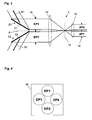
- Fig. 3 the beam path of a first embodiment of the optical arrangement according to the present invention is shown.
- This optical arrangement is provided in the region of the entrance aperture with a diaphragm 16, which, as in Fig. 4 has four entrance pupils EP1, EP2, EP3 and EP4.
- the pupil diaphragm can also be provided in the region of the exit aperture, as in FIG Fig. 3 is represented by the aperture 18, wherein the in Fig. 3 visible exit pupils AP1 and AP2 correspond to the entrance pupil EP1 and EP2 of the pupil diaphragm 16 provided in the region of the entrance aperture.
- Each of the pupils EP1 to EP4 of the optical arrangement is associated with a beam deflection device of which, in the beam path representation of FIG Fig. 3 only the upper beam deflector 20 and the lower beam deflector 22 are shown.
- Each of the beam deflection devices 20, 22 has a mirror 21, 23, by means of which the beam path assigned to the corresponding pupil EP1, EP2 is deflected such that the corresponding viewing direction B1, B2 is at an angle to the optical axis A.
- the angles of the individual mirrors 21, 23 and thus of the individual viewing directions B1, B2 to the optical axis A can be different.
- Strahlenumlenkvorraumen for the pupil EP3 and EP4 are formed analogously
- the invention is not limited to those in Fig. 4 shown pupil diaphragm 16 with four round pupils EP1 to EP4 limited.
- the multiple entrance pupil formed thereby can be designed as desired in number, shape and arrangement of the pupils.
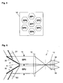
- Another example of such a multiple entrance pupil is in Fig. 5 shown, in which the pupil diaphragm 16 'is shown with seven each hexagonal in cross-section pupils, wherein six of the pupils EP1 to EP6 are arranged uniformly around the centrally arranged pupil EP7 around.
- the further processing of the radiation at the exit of the optical arrangement, ie behind the exit aperture, is independent of the invention. So, for example, as in Fig. 3 is shown, a single image can be generated for all pupils. Alternatively, however, as in Fig. 6 is shown, the imaging optics 1 in the region of the exit aperture downstream of the number of pupils corresponding number of further imaging optics 30, 32 may be provided. Each of the further imaging optics 30, 32 is assigned to one of the pupils, EP1, EP2. These further imaging optics 30, 32 cause each individual pupil to be tapped separately and imaged, for example, on an associated detector. The can individual further imaging optics can be focused separately from each other. In the Fig. 6 not shown further imaging optics, which are associated with the pupil EP3 and EP4, are formed analogously. The further imaging optics do not necessarily have to be arranged downstream of the imaging optics 1, but may alternatively also be integrated into the imaging optics 1.
Landscapes
- Physics & Mathematics (AREA)
- General Physics & Mathematics (AREA)
- Optics & Photonics (AREA)
- Astronomy & Astrophysics (AREA)
- Studio Devices (AREA)
- Stereoscopic And Panoramic Photography (AREA)
- Photometry And Measurement Of Optical Pulse Characteristics (AREA)
- Lenses (AREA)
Abstract
Description
- Die vorliegende Erfindung betrifft eine optische Anordnung zur Abbildung von in unterschiedlichen Blickrichtungen befindlichen Objekten.
- In vielen Anwendungsbereichen ist es erwünscht, unterschiedliche Objekte, die in unterschiedlichen Raumrichtungen oder Blickrichtungen liegen können, gleichzeitig beobachten oder detektieren zu können. Eine solche gleichzeitige Beobachtung oder Detektierung von räumlich getrennten Objekten, bei der man auch von "Parallelisierung" spricht, gestattet es, in einer Bildebene nur die auf die Objekte gerichteten Blickwinkelbereiche darzustellen und zwischen den Objekten gelegene "uninteressante" Raumbereiche auszublenden.
- Bekannt ist es, für eine derartige parallele Beobachtung in unterschiedliche Raumrichtungen oder Blickrichtungen eine Mehrzahl von Optiken zu verwenden, die jeweils einer bestimmten Blickrichtung zugeordnet sind. Ein Beispiel dafür sind die MOMS-Kameras, die im Raumlabor Spacelab und in der Raumstation Mir als Stereokameras eingesetzt wurden. Nachteilig bei derartigen Lösungen ist es, dass durch das Vorsehen von zwei oder mehr Optiken der Zusammenbau und die Ausrichtung und Kalibrierung der gesamten optischen Anordnung zeitlich aufwendig und technisch schwierig sind. Zudem ist eine derartige optische Anordnung aufgrund der Mehrzahl der vorgesehenen Optiken nicht sehr kompakt.
- Aufgabe der vorliegenden Erfindung ist es daher, eine gattungsgemäße optische Anordnung zu schaffen, die weniger komplex und damit kostengünstiger, sowie robuster bezüglich Alignment bzw. Dejustage ist.
- Diese Aufgabe wird durch die im Patentanspruch 1 angegebene optische Anordnung gelöst.
- Erfindungsgemäß ist diese optische Anordnung versehen mit einer Abbildungsoptik, die entlang einer optischen Achse angeordnete abbildende Elemente aufweist, mit einer Eintrittspupille und einer Austrittspupille, einer im Bereich der Eintrittsapertur und/oder der Austrittsapertur angeordneten Mehrfach-Pupillenblende und zumindest einer vor der Eintrittsapertur angeordneten Strahlenumlenkvorrichtung, die einer der von der Mehrfach-Pupillenblende gebildeten Pupillen zugeordnet ist.
- Durch diese erfindungsgemäße Ausgestaltung der optischen Anordnung ist es möglich, unterschiedliche Blickrichtungen zu parallelisieren und mit nur einer einzigen Abbildungsoptik auf eine Bildebene oder einen für die gewünschte Beobachtung oder Detektierung geeigneten Sensor zu projizieren. Die Vorteile einer solchen erfindungsgemäßen Parallelisierung im Vergleich zu der herkömmlichen Parallelisierung durch separate Optiken liegt in ersten Linie darin, dass bei der optischen Anordnung gemäß der Erfindung nur eine einzige Abbildungsoptik verwendet wird, sodass der Zusammenbau und die Ausrichtung sowie die Kalibrierung eines mit der erfindungsgemäßen optischen Anordnung versehenen Instruments weniger zeitaufwendig und technisch einfacher sind, und das resultierende Instrument intrinsisch stabil gegen Dejustage ist. Dadurch reduzieren sich die Kosten und das Risiko von Fehlfunktionen wird ebenfalls herabgesetzt. Außerdem lässt sich eine derartige optische Anordnung wesentlich kompakter aufbauen, sodass sowohl das Volumen als auch die Masse eines mit dieser erfindungsgemäßen optischen Anordnung versehenen Instruments gegenüber dem Stand der Technik reduziert sind.
- Vorzugsweise ist jeder der von der Mehrfach-Pupillenblende gebildeten Pupillen eine Strahlenumlenkvorrichtung zugeordnet. Dadurch können alle Pupillen in unterschiedlichen Richtungen "sehen". Es ist aber auch möglich, eine der Pupillen nicht mit einer Strahlenumlenkvorrichtung zu versehen, sodass durch diese Pupille parallel zur optischen Achse "geradeaus gesehen" werden kann.
- Vorteilhaft ist es, wenn die jeweilige Strahlenumlenkvorrichtung zumindest einen Spiegel aufweist.
- In einer weiteren vorteilhaften Ausgestaltung der Erfindung ist hinter der Austrittsapertur der Abbildungsoptik zumindest eine weitere Abbildungsoptik vorgesehen, die einer der von der Mehrfach-Pupillenblende gebildeten Pupillen zugeordnet ist. Diese zusätzliche weitere Abbildungsoptik gestattet es, für die entsprechende Pupille eine unabhängige Abbildung des dieser Pupille zugeordneten Objekts in einer eigenständigen Bildebene vorzunehmen.
- Dabei ist es besonders von Vorteil, wenn eine der Anzahl der Pupillen entsprechende Anzahl von weiteren Abbildungsoptiken vorgesehen ist, wobei jede der weiteren Abbildungsoptiken einer der Pupillen zugeordnet ist. Bei dieser Ausführungsform kann somit für jede der Pupillen unabhängig voneinander eine separate Abbildung des entsprechenden Objekts erfolgen.
- Es kann auch von Vorteil sein, wenn die Abbildungsoptik derart ausgestaltet ist, dass die von der Mehrfach-Pupillenblende erzeugten Bilder, vorzugsweise separat voneinander, fokussierbar sind. Dadurch können beispielsweise die einzelnen Pupillen zugeordneten Objekte an unterschiedlichen Orten hinter der Abbildungs-Abbildung der einzelnen Objekte auf unterschiedlichen Sensoren vorgenommen werden soll.
- Bevorzugte Ausführungsbeispiele der Erfindung mit zusätzlichen Ausgestaltungsdetails und weiteren Vorteilen sind nachfolgend unter Bezugnahme auf die beigefügten Zeichnungen näher beschrieben und erläutert.
- Es zeigt:
- Fig. 1
- ein grundlegendes Beispiel des Strahlengangs einer optischen Anordnung zur Abbildung von einem Objekt, das nicht in Richtung der optischen Achse der Abbildungsoptik gelegen ist;
- Fig. 2
- die zu der optischen Anordnung aus
Fig. 1 gehörende Eintrittspupille; - Fig. 3
- Eine erste erfindungsgemäße optische Anordnung in schematischer Darstellung des Strahlengangs;
- Fig. 4
- Die Anordnung der Eintrittspupillen in der optischen Anordnung aus
Fig. 3 ; - Fig. 5
- Die Darstellung der Eintrittspupillen in einer anderen Ausgestaltung der erfinderischen optischen Anordnung und
- Fig. 6
- Eine schematische Darstellung des Strahlengangs in einer dritten Ausführungsform der erfindungsgemäßen optischen Anordnung.
- Fig. 7
- Eine schematische Darstellung des Strahlengangs in einer vierten Ausführungsform der erfindungsgemäßen optischen Anordnung.
-
Fig. 1 zeigt das Grundprinzip einer optischen Anordnung, bei der die Blickrichtung B nicht in Richtung der optischen Achse A liegt. Diese optische Anordnung weist eine Abbildungsoptik 1 sowie eine Strahlenumlenkvorrichtung 2 auf. Die Abbildungsoptik 1 weist entlang der optischen Achse A angeordnete abbildende Elemente 10, 12 auf, die hier durch zwei Linsensymbole dargestellt sind. Die Erfindung ist aber nicht auf einer Abbildungsoptik mit Linsen beschränkt, sondern bezieht sich auf eine beliebige Optik. Sie kann somit aus beliebig vielen unterschiedlichen abbildenden Elementen bestehen. Die abbildenden Elemente können beispielsweise refraktive Linsen oder auch Spiegellinsen sein. In gezeigtem Beispiel stellt die dargestellte Abbildungsoptik ein afokales Teleskop mit einer Zwischenbildebene 14 dar. Die Blickrichtung B der Abbildungsoptik 1 ist der Richtung des eintretenden Lichts entgegengesetzt. - Die in
Fig. 1 dargestellte konventionelle optische Anordnung besitzt nur eine einzige Apertur und damit eine einzelne Eintrittspupille EP sowie eine einzige Austrittspupille AP. Der Blick auf die Eintrittspupille EP aus der Richtung des in das Objektiv eintretenden Lichts (also entgegen dem Pfeil B) ist inFig. 2 dargestellt. In diesem gezeigten Beispiel ist die einzige Eintrittspupille EP rund ausgebildet. - In
Fig. 3 ist der Strahlengang einer ersten Ausführungsform der optischen Anordnung gemäß der vorliegenden Erfindung dargestellt. Diese optische Anordnung ist im Bereich der Eintrittsapertur mit einer Blende 16 versehen, die, wie inFig. 4 dargestellt ist, vier Eintrittspupillen EP1, EP2, EP3 und EP4 aufweist. Statt im Bereich der Eintrittsapertur kann die Pupillenblende auch im Bereich der Austrittsapertur vorgesehen sein, wie inFig. 3 durch die Blende 18 dargestellt ist, wobei die inFig. 3 sichtbaren Austrittspupillen AP1und AP2 den Eintrittspupillen EP1 und EP2 der im Bereich der Eintrittsapertur vorgesehenen Pupillenblende 16 entsprechen. - Jeder der Pupillen EP1 bis EP4 der optischen Anordnung ist eine Strahlenumlenkvorrichtung zugeordnet, von der in der Strahlengangdarstellung der
Fig. 3 nur die obere Strahlenumlenkvorrichtung 20 und die untere Strahlenumlenkvorrichtung 22 dargestellt sind. Jede der Strahlenumlenkvorrichtungen 20, 22 weist einen Spiegel 21, 23 auf, mittels welchem der der entsprechenden Pupille EP1, EP2 zugeordnete Strahlengang so umgelenkt wird, dass die entsprechende Blickrichtung B1, B2 in einem Winkel zur optischen Achse A steht. Die Winkel der einzelnen Spiegel 21, 23 und somit der einzelnen Blickrichtungen B1, B2 zur optischen Achse A können unterschiedlich sein. Die inFig. 3 nicht dargestellten Strahlenumlenkvorrichtungen für die Pupillen EP3 und EP4 sind analog ausgebildet - Die Erfindung ist nicht auf die in
Fig. 4 dargestellte Pupillenblende 16 mit vier runden Pupillen EP1 bis EP4 beschränkt. Die dadurch gebildete Mehrfach-Eintrittspupille kann in Anzahl, Form und Anordnung der Pupillen beliebig gestaltet sein. Ein weiteres Beispiel für eine derartige Mehrfach-Eintrittspupille ist inFig. 5 dargestellt, bei der die Pupillenblende 16' mit sieben jeweils im Querschnitt sechseckigen Pupillen dargestellt ist, wobei sechs der Pupillen EP1 bis EP6 gleichmäßig um die zentral angeordnete Pupille EP7 herum angeordnet sind. - Die Weiterverarbeitung der Strahlung am Ausgang der optischen Anordnung, also hinter der Austrittsapertur, ist unabhängig von der Erfindung. So kann zum Beispiel, wie in
Fig. 3 dargestellt ist, ein einziges Bild für alle Pupillen erzeugt werden. Alternativ kann aber auch, wie inFig. 6 dargestellt ist, der Abbildungsoptik 1 im Bereich der Austrittsapertur nachgeordnet eine der Anzahl der Pupillen entsprechende Anzahl von weiteren Abbildungsoptiken 30, 32 vorgesehen sein. Dabei ist jede der weiteren Abbildungsoptiken 30, 32 einer der Pupillen, EP1, EP2 zugeordnet. Diese weiteren Abbildungsoptiken 30, 32 bewirken, dass jede einzelne Pupille separat abgegriffen und beispielsweise auf einem zugeordneten Detektor abgebildet werden kann. Dabei können die einzelnen weiteren Abbildungsoptiken separat voneinander fokussierbar sein. Die inFig. 6 nicht gezeigten weiteren Abbildungsoptiken, die den Pupillen EP3 und EP4 zugeordnet sind, sind analog ausgebildet. Die weiteren Abbildungsoptiken müssen nicht notwendigerweise der Abbildungsoptik 1 nachgeordnet sein, sondern können alternativ auch in die Abbildungsoptik 1 integriert sein. - Bei der erfindungsgemäßen optischen Anordnung werden somit mehrere Eintrittspupillen, die unterschiedliche Blickrichtungen aufweisen, von der einzigen Abbildungsoptik 1 erfasst. Hierdurch ist ein sehr kompakter Aufbau einer optischen Anordnung zur Abbildung von in unterschiedlichen Blickrichtungen befindlichen Objekten möglich. Ein weiterer Vorteil besteht darin, dass in der erfindungsgemäßen Anordnung nicht-abbildende optische Elemente nur einmal, nämlich in der einzigen Abbildungsoptik 1, vorgesehen zu werden brauchen. Ein Beispiel dafür ist in
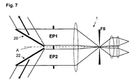
Fig. 7 dargestellt, in der die optische Anordnung der ausFig. 6 entspricht, und wobei in der Zwischenbildebene eine Feldblende FS angeordnet ist. Mittels dieser Feldblende kann auf einfache zentrale Weise Streulicht und Hintergrundlicht (z.B. thermische Hintergrundstrahlung bei Infrarotinstrumenten) ausgeblendet werden. Wenn außerdem, wie dies in den beschriebenen Beispielen der Fall ist, die Sichtfelder der einzelnen Eintrittspupillen beziehungsweise Blickrichtungen gleich groß oder ähnlich groß sind, dann kann mit der einzigen Feldblende FS effizient das Feld aller Eintrittspupillen beziehungsweise Blickrichtungen ausgeblendet werden. - Bezugszeichen in den Ansprüchen, der Beschreibung und den Zeichnungen dienen lediglich dem besseren Verständnis der Erfindung und sollen den Schutzumfang nicht einschränken.
- Es bezeichnen:
- 1
- Abbildungsoptik
- 2
- Strahlenumlenkvorrichtung
- 10
- abbildendes Element
- 12
- abbildendes Element
- 14
- Zwischenbildebene
- 16
- Blende in der Entrittspupille
- 16'
- Blende in der Entrittspupille
- 18
- Blende in der Austrittspupille
- 20
- obere Strahlenumlenkvorrichtung
- 21
- Spiegel
- 22
- untere Strahlenumlenkvorrichtung
- 23
- Spiegel
- 30
- Abbildungsoptik
- 32
- Abbildungsoptik
- A
- Achse
- B
- Blickrichtung
- AP
- Austrittspupille
- EP
- Eintrittspupille
- FS
- Feldblende
Claims (7)
- Optische Anordnung zur Abbildung von in unterschiedlichen Blickrichtungen (B; B1, B2) befindlichen Objekten, mit- einer Abbildungsoptik (1), die entlang einer optischen Achse (A) angeordnete abbildende Elemente (10, 12) aufweist, mit einer Eintrittsapertur und einer Austrittsapertur;- einer im Bereich der Eintrittsapertur und/oder der Austrittsapertur angeordneten Mehrfach-Pupillenblende (16; 18; 16') und- zumindest einer vor der Eintrittsapertur angeordneten Strahlenumlenkvorrichtung (20, 22), die jeweils einer der von der Mehrfach-Pupillenblende (16; 18; 16') gebildeten Pupillen (EP1, EP2, EP3, EP4) zugeordnet ist,- wobei die abbildenden Elemente der einen Abbildungsoptik (1) die Strahlengänge aller Pupillen (EP1, EP2, EP3, EP4) erfassen.
- Optische Anordnung nach Anspruch 1
dadurch gekennzeichnet,
dass jeder der von der Mehrfach-Pupillenblende (16; 18; 16') gebildeten Pupillen (EP1, EP2) eine Strahlenumlenkvorrichtung (20, 22) zugeordnet ist. - Optische Anordnung nach Anspruch 1 oder 2,
dadurch gekennzeichnet,
dass die jeweilige Strahlenumlenkvorrichtung (20, 22) zumindest einen Spiegel (21, 23) aufweist. - Optische Anordnung nach Anspruch 1, 2 oder 3,
dadurch gekennzeichnet,
dass hinter der Austrittsapertur zumindest eine weitere Abbildungsoptik (30, 32) vorgesehen ist, die einer der von der Mehrfach-Pupillenblende (16; 18; 16') gebildeten Pupillen (EP1, EP2) zugeordnet ist. - Optische Anordnung nach Anspruch 4,
dadurch gekennzeichnet,
dass eine der Anzahl der Pupillen entsprechende Anzahl von weiteren Abbildungsoptiken (30, 32) vorgesehen ist, wobei jede weitere Abbildungsoptik (30, 32) einer der Pupillen (EP1, EP2) zugeordnet ist. - Optische Anordnung nach einem der Ansprüche 4 oder 5,
dadurch gekennzeichnet,
dass die weiteren Abbildungsoptiken (30, 32) derart ausgestaltet sind, dass die von der Mehrfach-Pupillenblende (16; 18; 16') erzeugten Bilder, vorzugsweise separat voneinander, fokussierbar sind. - Optische Anordnung nach einem der vorhergehenden Ansprüche,
dadurch gekennzeichnet,
dass in der Zwischenbildebene (14) der Abbildungsoptik (1) eine Feldblende (FS) vorgesehen ist.
Applications Claiming Priority (1)
| Application Number | Priority Date | Filing Date | Title |
|---|---|---|---|
| DE102009024884.6A DE102009024884B4 (de) | 2009-06-09 | 2009-06-09 | Optische Anordnung zur Abbildung von in unterschiedlichen Blickrichtungen befindlichen Objekten |
Publications (3)
| Publication Number | Publication Date |
|---|---|
| EP2261725A2 true EP2261725A2 (de) | 2010-12-15 |
| EP2261725A3 EP2261725A3 (de) | 2011-09-21 |
| EP2261725B1 EP2261725B1 (de) | 2013-09-18 |
Family
ID=42830346
Family Applications (1)
| Application Number | Title | Priority Date | Filing Date |
|---|---|---|---|
| EP10005794.2A Active EP2261725B1 (de) | 2009-06-09 | 2010-06-04 | Optische Anordnung zur Abbildung von in unterschiedlichen Blickrichtungen befindlichen Objekten |
Country Status (2)
| Country | Link |
|---|---|
| EP (1) | EP2261725B1 (de) |
| DE (1) | DE102009024884B4 (de) |
Cited By (1)
| Publication number | Priority date | Publication date | Assignee | Title |
|---|---|---|---|---|
| FR2995448A1 (fr) * | 2012-09-13 | 2014-03-14 | Centre Nat Etd Spatiales | Dispositif optique d'emission et de detection de rayons lumineux |
Family Cites Families (4)
| Publication number | Priority date | Publication date | Assignee | Title |
|---|---|---|---|---|
| US3055265A (en) | 1959-09-18 | 1962-09-25 | Rowe E Carney Jr | Motion picture camera for making panoramic pictures |
| DE3006657A1 (de) | 1980-02-22 | 1981-09-03 | Ernst Leitz Wetzlar Gmbh, 6330 Wetzlar | Vergleichsmakroskop bzw. -mikroskop |
| US7522337B2 (en) | 2004-06-10 | 2009-04-21 | Raytheon Company | Compact multi-entrance-pupil imaging optical system |
| US7626150B2 (en) * | 2007-03-05 | 2009-12-01 | Raytheon Company | System and method for capturing image data over a wide field of view with high resolution |
-
2009
- 2009-06-09 DE DE102009024884.6A patent/DE102009024884B4/de active Active
-
2010
- 2010-06-04 EP EP10005794.2A patent/EP2261725B1/de active Active
Non-Patent Citations (1)
| Title |
|---|
| None |
Cited By (1)
| Publication number | Priority date | Publication date | Assignee | Title |
|---|---|---|---|---|
| FR2995448A1 (fr) * | 2012-09-13 | 2014-03-14 | Centre Nat Etd Spatiales | Dispositif optique d'emission et de detection de rayons lumineux |
Also Published As
| Publication number | Publication date |
|---|---|
| DE102009024884A1 (de) | 2010-12-30 |
| DE102009024884B4 (de) | 2019-08-22 |
| EP2261725B1 (de) | 2013-09-18 |
| EP2261725A3 (de) | 2011-09-21 |
Similar Documents
| Publication | Publication Date | Title |
|---|---|---|
| EP2388633B1 (de) | Kamera mit mehreren Festbrennweiten | |
| DE102009000550B4 (de) | Weitwinkelbildgebungssystem für die Bereitstellung eines Bildes der Umgebung eines Fahrzeugs, insbesondere eines Kraftfahrzeugs | |
| EP2507662B1 (de) | Vorrichtung zur optischen abbildung | |
| DE102012108424A1 (de) | Optisches System mit einer GRIN-Optik und Vorrichtung mit zumindest zwei optischen Systemen | |
| EP3596506B1 (de) | Optische abstrahlvorrichtung für laserpulse mit selektiver optik | |
| WO2012034852A1 (de) | Optisches abbildungssystem zur multispektralen bildgebung | |
| DE102015226460A1 (de) | LIDAR-Abtasteinrichtung und LIDAR-Abtasteinrichtungssystem | |
| EP2469320B1 (de) | Verfahren zum Betreiben eines konfokales Laser-Scanning-Mikroskops mit einstellbarem Pinhole in Form einer matrixartigen Verteilung einzeln auslesbarer Empfängerelemente | |
| EP1983334B1 (de) | Verfahren und Vorrichtung zur optischen Erfassung von Verschmutzungen | |
| DE19904687A1 (de) | Richtbare Teleskopanordnung | |
| DE10029680B4 (de) | Mikroskop-Aufbau | |
| DE102014215100B4 (de) | Zoommikroskop | |
| EP2261725B1 (de) | Optische Anordnung zur Abbildung von in unterschiedlichen Blickrichtungen befindlichen Objekten | |
| EP3610307B1 (de) | Monozentrische empfangsanordnung | |
| EP4127810B1 (de) | Optische anordnung für ein schiefeebenenmikroskop zur verbesserung der auflösung | |
| EP2818094A1 (de) | Beobachtungsinstrument mit einem symmetrischen Bildfeld unter Verwendung asymmetrischer Bildsensoren | |
| DE102016008884A1 (de) | Spektroskopievorrichtung und -verfahren | |
| DE102015100695B4 (de) | Optische Anordnung für ein Laser-Scanner-System | |
| DE102006045839A1 (de) | Laserscanningmikroskop mit Element zur Pupillenmanipulation | |
| DE102005023137B4 (de) | Anordnung zur hochauflösenden digitalen Inline-Holographie | |
| DE102021202164B3 (de) | Tandemblendenarchitektur zur Füllfaktorerhöhung von kompakten Multikanalabbildungssystemen | |
| DE19720903B4 (de) | Einrichtung zur Achsparallelisierung eines Wärmebildgerätes | |
| DE102007039988B4 (de) | Mikroskop | |
| DE102018113136A1 (de) | Kameramodul und Kamerasystem mit einem Kameramodul | |
| DE102013221878A1 (de) | Fahrerassistenzsystem mit einer Kamera mit ungleichförmiger Winkelauflösung |
Legal Events
| Date | Code | Title | Description |
|---|---|---|---|
| PUAI | Public reference made under article 153(3) epc to a published international application that has entered the european phase |
Free format text: ORIGINAL CODE: 0009012 |
|
| AK | Designated contracting states |
Kind code of ref document: A2 Designated state(s): AL AT BE BG CH CY CZ DE DK EE ES FI FR GB GR HR HU IE IS IT LI LT LU LV MC MK MT NL NO PL PT RO SE SI SK SM TR |
|
| AX | Request for extension of the european patent |
Extension state: BA ME RS |
|
| RIN1 | Information on inventor provided before grant (corrected) |
Inventor name: HOLOTA, WOLFGANG, DR. Inventor name: GULDE, STEPHAN, DR. |
|
| RIN1 | Information on inventor provided before grant (corrected) |
Inventor name: GULDE, STEPHAN, DR. Inventor name: HOLOTA, WOLFGANG, DR. |
|
| PUAL | Search report despatched |
Free format text: ORIGINAL CODE: 0009013 |
|
| AK | Designated contracting states |
Kind code of ref document: A3 Designated state(s): AL AT BE BG CH CY CZ DE DK EE ES FI FR GB GR HR HU IE IS IT LI LT LU LV MC MK MT NL NO PL PT RO SE SI SK SM TR |
|
| AX | Request for extension of the european patent |
Extension state: BA ME RS |
|
| RIC1 | Information provided on ipc code assigned before grant |
Ipc: G02B 27/22 20060101AFI20110815BHEP Ipc: G02B 23/02 20060101ALI20110815BHEP Ipc: G02B 13/06 20060101ALI20110815BHEP |
|
| 17P | Request for examination filed |
Effective date: 20120308 |
|
| GRAP | Despatch of communication of intention to grant a patent |
Free format text: ORIGINAL CODE: EPIDOSNIGR1 |
|
| INTG | Intention to grant announced |
Effective date: 20130415 |
|
| GRAS | Grant fee paid |
Free format text: ORIGINAL CODE: EPIDOSNIGR3 |
|
| GRAA | (expected) grant |
Free format text: ORIGINAL CODE: 0009210 |
|
| AK | Designated contracting states |
Kind code of ref document: B1 Designated state(s): AL AT BE BG CH CY CZ DE DK EE ES FI FR GB GR HR HU IE IS IT LI LT LU LV MC MK MT NL NO PL PT RO SE SI SK SM TR |
|
| REG | Reference to a national code |
Ref country code: GB Ref legal event code: FG4D Free format text: NOT ENGLISH |
|
| REG | Reference to a national code |
Ref country code: CH Ref legal event code: EP |
|
| REG | Reference to a national code |
Ref country code: IE Ref legal event code: FG4D Free format text: LANGUAGE OF EP DOCUMENT: GERMAN |
|
| REG | Reference to a national code |
Ref country code: AT Ref legal event code: REF Ref document number: 633074 Country of ref document: AT Kind code of ref document: T Effective date: 20131015 |
|
| REG | Reference to a national code |
Ref country code: DE Ref legal event code: R096 Ref document number: 502010004750 Country of ref document: DE Effective date: 20131114 |
|
| REG | Reference to a national code |
Ref country code: NL Ref legal event code: T3 |
|
| PG25 | Lapsed in a contracting state [announced via postgrant information from national office to epo] |
Ref country code: SE Free format text: LAPSE BECAUSE OF FAILURE TO SUBMIT A TRANSLATION OF THE DESCRIPTION OR TO PAY THE FEE WITHIN THE PRESCRIBED TIME-LIMIT Effective date: 20130918 Ref country code: LT Free format text: LAPSE BECAUSE OF FAILURE TO SUBMIT A TRANSLATION OF THE DESCRIPTION OR TO PAY THE FEE WITHIN THE PRESCRIBED TIME-LIMIT Effective date: 20130918 Ref country code: NO Free format text: LAPSE BECAUSE OF FAILURE TO SUBMIT A TRANSLATION OF THE DESCRIPTION OR TO PAY THE FEE WITHIN THE PRESCRIBED TIME-LIMIT Effective date: 20131218 Ref country code: HR Free format text: LAPSE BECAUSE OF FAILURE TO SUBMIT A TRANSLATION OF THE DESCRIPTION OR TO PAY THE FEE WITHIN THE PRESCRIBED TIME-LIMIT Effective date: 20130918 Ref country code: CY Free format text: LAPSE BECAUSE OF FAILURE TO SUBMIT A TRANSLATION OF THE DESCRIPTION OR TO PAY THE FEE WITHIN THE PRESCRIBED TIME-LIMIT Effective date: 20130911 |
|
| REG | Reference to a national code |
Ref country code: LT Ref legal event code: MG4D |
|
| PG25 | Lapsed in a contracting state [announced via postgrant information from national office to epo] |
Ref country code: SI Free format text: LAPSE BECAUSE OF FAILURE TO SUBMIT A TRANSLATION OF THE DESCRIPTION OR TO PAY THE FEE WITHIN THE PRESCRIBED TIME-LIMIT Effective date: 20130918 Ref country code: FI Free format text: LAPSE BECAUSE OF FAILURE TO SUBMIT A TRANSLATION OF THE DESCRIPTION OR TO PAY THE FEE WITHIN THE PRESCRIBED TIME-LIMIT Effective date: 20130918 Ref country code: LV Free format text: LAPSE BECAUSE OF FAILURE TO SUBMIT A TRANSLATION OF THE DESCRIPTION OR TO PAY THE FEE WITHIN THE PRESCRIBED TIME-LIMIT Effective date: 20130918 Ref country code: GR Free format text: LAPSE BECAUSE OF FAILURE TO SUBMIT A TRANSLATION OF THE DESCRIPTION OR TO PAY THE FEE WITHIN THE PRESCRIBED TIME-LIMIT Effective date: 20131219 |
|
| PG25 | Lapsed in a contracting state [announced via postgrant information from national office to epo] |
Ref country code: CY Free format text: LAPSE BECAUSE OF FAILURE TO SUBMIT A TRANSLATION OF THE DESCRIPTION OR TO PAY THE FEE WITHIN THE PRESCRIBED TIME-LIMIT Effective date: 20130918 |
|
| PG25 | Lapsed in a contracting state [announced via postgrant information from national office to epo] |
Ref country code: EE Free format text: LAPSE BECAUSE OF FAILURE TO SUBMIT A TRANSLATION OF THE DESCRIPTION OR TO PAY THE FEE WITHIN THE PRESCRIBED TIME-LIMIT Effective date: 20130918 Ref country code: IS Free format text: LAPSE BECAUSE OF FAILURE TO SUBMIT A TRANSLATION OF THE DESCRIPTION OR TO PAY THE FEE WITHIN THE PRESCRIBED TIME-LIMIT Effective date: 20140118 Ref country code: CZ Free format text: LAPSE BECAUSE OF FAILURE TO SUBMIT A TRANSLATION OF THE DESCRIPTION OR TO PAY THE FEE WITHIN THE PRESCRIBED TIME-LIMIT Effective date: 20130918 Ref country code: SK Free format text: LAPSE BECAUSE OF FAILURE TO SUBMIT A TRANSLATION OF THE DESCRIPTION OR TO PAY THE FEE WITHIN THE PRESCRIBED TIME-LIMIT Effective date: 20130918 |
|
| PG25 | Lapsed in a contracting state [announced via postgrant information from national office to epo] |
Ref country code: PL Free format text: LAPSE BECAUSE OF FAILURE TO SUBMIT A TRANSLATION OF THE DESCRIPTION OR TO PAY THE FEE WITHIN THE PRESCRIBED TIME-LIMIT Effective date: 20130918 Ref country code: ES Free format text: LAPSE BECAUSE OF FAILURE TO SUBMIT A TRANSLATION OF THE DESCRIPTION OR TO PAY THE FEE WITHIN THE PRESCRIBED TIME-LIMIT Effective date: 20130918 |
|
| REG | Reference to a national code |
Ref country code: DE Ref legal event code: R097 Ref document number: 502010004750 Country of ref document: DE |
|
| PG25 | Lapsed in a contracting state [announced via postgrant information from national office to epo] |
Ref country code: PT Free format text: LAPSE BECAUSE OF FAILURE TO SUBMIT A TRANSLATION OF THE DESCRIPTION OR TO PAY THE FEE WITHIN THE PRESCRIBED TIME-LIMIT Effective date: 20140120 |
|
| PLBE | No opposition filed within time limit |
Free format text: ORIGINAL CODE: 0009261 |
|
| STAA | Information on the status of an ep patent application or granted ep patent |
Free format text: STATUS: NO OPPOSITION FILED WITHIN TIME LIMIT |
|
| 26N | No opposition filed |
Effective date: 20140619 |
|
| PG25 | Lapsed in a contracting state [announced via postgrant information from national office to epo] |
Ref country code: DK Free format text: LAPSE BECAUSE OF FAILURE TO SUBMIT A TRANSLATION OF THE DESCRIPTION OR TO PAY THE FEE WITHIN THE PRESCRIBED TIME-LIMIT Effective date: 20130918 |
|
| REG | Reference to a national code |
Ref country code: DE Ref legal event code: R097 Ref document number: 502010004750 Country of ref document: DE Effective date: 20140619 |
|
| PG25 | Lapsed in a contracting state [announced via postgrant information from national office to epo] |
Ref country code: MC Free format text: LAPSE BECAUSE OF FAILURE TO SUBMIT A TRANSLATION OF THE DESCRIPTION OR TO PAY THE FEE WITHIN THE PRESCRIBED TIME-LIMIT Effective date: 20130918 Ref country code: LU Free format text: LAPSE BECAUSE OF FAILURE TO SUBMIT A TRANSLATION OF THE DESCRIPTION OR TO PAY THE FEE WITHIN THE PRESCRIBED TIME-LIMIT Effective date: 20140604 |
|
| REG | Reference to a national code |
Ref country code: CH Ref legal event code: PL |
|
| GBPC | Gb: european patent ceased through non-payment of renewal fee |
Effective date: 20140604 |
|
| REG | Reference to a national code |
Ref country code: IE Ref legal event code: MM4A |
|
| PG25 | Lapsed in a contracting state [announced via postgrant information from national office to epo] |
Ref country code: LI Free format text: LAPSE BECAUSE OF NON-PAYMENT OF DUE FEES Effective date: 20140630 Ref country code: CH Free format text: LAPSE BECAUSE OF NON-PAYMENT OF DUE FEES Effective date: 20140630 Ref country code: IE Free format text: LAPSE BECAUSE OF NON-PAYMENT OF DUE FEES Effective date: 20140604 |
|
| PG25 | Lapsed in a contracting state [announced via postgrant information from national office to epo] |
Ref country code: GB Free format text: LAPSE BECAUSE OF NON-PAYMENT OF DUE FEES Effective date: 20140604 |
|
| REG | Reference to a national code |
Ref country code: FR Ref legal event code: PLFP Year of fee payment: 6 |
|
| PG25 | Lapsed in a contracting state [announced via postgrant information from national office to epo] |
Ref country code: MT Free format text: LAPSE BECAUSE OF FAILURE TO SUBMIT A TRANSLATION OF THE DESCRIPTION OR TO PAY THE FEE WITHIN THE PRESCRIBED TIME-LIMIT Effective date: 20130918 |
|
| PG25 | Lapsed in a contracting state [announced via postgrant information from national office to epo] |
Ref country code: SM Free format text: LAPSE BECAUSE OF FAILURE TO SUBMIT A TRANSLATION OF THE DESCRIPTION OR TO PAY THE FEE WITHIN THE PRESCRIBED TIME-LIMIT Effective date: 20130918 |
|
| PG25 | Lapsed in a contracting state [announced via postgrant information from national office to epo] |
Ref country code: RO Free format text: LAPSE BECAUSE OF FAILURE TO SUBMIT A TRANSLATION OF THE DESCRIPTION OR TO PAY THE FEE WITHIN THE PRESCRIBED TIME-LIMIT Effective date: 20130918 |
|
| REG | Reference to a national code |
Ref country code: FR Ref legal event code: PLFP Year of fee payment: 7 |
|
| PG25 | Lapsed in a contracting state [announced via postgrant information from national office to epo] |
Ref country code: BG Free format text: LAPSE BECAUSE OF FAILURE TO SUBMIT A TRANSLATION OF THE DESCRIPTION OR TO PAY THE FEE WITHIN THE PRESCRIBED TIME-LIMIT Effective date: 20130918 |
|
| PG25 | Lapsed in a contracting state [announced via postgrant information from national office to epo] |
Ref country code: TR Free format text: LAPSE BECAUSE OF FAILURE TO SUBMIT A TRANSLATION OF THE DESCRIPTION OR TO PAY THE FEE WITHIN THE PRESCRIBED TIME-LIMIT Effective date: 20130918 Ref country code: HU Free format text: LAPSE BECAUSE OF FAILURE TO SUBMIT A TRANSLATION OF THE DESCRIPTION OR TO PAY THE FEE WITHIN THE PRESCRIBED TIME-LIMIT; INVALID AB INITIO Effective date: 20100604 Ref country code: BE Free format text: LAPSE BECAUSE OF FAILURE TO SUBMIT A TRANSLATION OF THE DESCRIPTION OR TO PAY THE FEE WITHIN THE PRESCRIBED TIME-LIMIT Effective date: 20140630 |
|
| REG | Reference to a national code |
Ref country code: AT Ref legal event code: MM01 Ref document number: 633074 Country of ref document: AT Kind code of ref document: T Effective date: 20150604 |
|
| PG25 | Lapsed in a contracting state [announced via postgrant information from national office to epo] |
Ref country code: AT Free format text: LAPSE BECAUSE OF NON-PAYMENT OF DUE FEES Effective date: 20150604 |
|
| REG | Reference to a national code |
Ref country code: FR Ref legal event code: PLFP Year of fee payment: 8 |
|
| REG | Reference to a national code |
Ref country code: DE Ref legal event code: R081 Ref document number: 502010004750 Country of ref document: DE Owner name: AIRBUS DEFENCE AND SPACE GMBH, DE Free format text: FORMER OWNER: ASTRIUM GMBH, 82024 TAUFKIRCHEN, DE |
|
| REG | Reference to a national code |
Ref country code: NL Ref legal event code: HC Owner name: AIRBUS DS GMBH; DE Free format text: DETAILS ASSIGNMENT: CHANGE OF OWNER(S), CHANGE OF OWNER(S) NAME; FORMER OWNER NAME: ASTRIUM GMBH Effective date: 20180220 Ref country code: NL Ref legal event code: PD Owner name: AIRBUS DEFENCE AND SPACE GMBH; DE Free format text: DETAILS ASSIGNMENT: CHANGE OF OWNER(S), MERGE; FORMER OWNER NAME: AIRBUS DS GMBH Effective date: 20180220 |
|
| REG | Reference to a national code |
Ref country code: FR Ref legal event code: PLFP Year of fee payment: 9 |
|
| PG25 | Lapsed in a contracting state [announced via postgrant information from national office to epo] |
Ref country code: MK Free format text: LAPSE BECAUSE OF FAILURE TO SUBMIT A TRANSLATION OF THE DESCRIPTION OR TO PAY THE FEE WITHIN THE PRESCRIBED TIME-LIMIT Effective date: 20130918 |
|
| REG | Reference to a national code |
Ref country code: FR Ref legal event code: CD Owner name: AIRBUS DS GMBH, DE Effective date: 20180718 |
|
| PG25 | Lapsed in a contracting state [announced via postgrant information from national office to epo] |
Ref country code: AL Free format text: LAPSE BECAUSE OF FAILURE TO SUBMIT A TRANSLATION OF THE DESCRIPTION OR TO PAY THE FEE WITHIN THE PRESCRIBED TIME-LIMIT Effective date: 20130918 |
|
| REG | Reference to a national code |
Ref country code: DE Ref legal event code: R079 Ref document number: 502010004750 Country of ref document: DE Free format text: PREVIOUS MAIN CLASS: G02B0027220000 Ipc: G02B0030000000 |
|
| PGFP | Annual fee paid to national office [announced via postgrant information from national office to epo] |
Ref country code: NL Payment date: 20220620 Year of fee payment: 13 Ref country code: IT Payment date: 20220627 Year of fee payment: 13 |
|
| PGFP | Annual fee paid to national office [announced via postgrant information from national office to epo] |
Ref country code: FR Payment date: 20220628 Year of fee payment: 13 |
|
| REG | Reference to a national code |
Ref country code: NL Ref legal event code: MM Effective date: 20230701 |
|
| PG25 | Lapsed in a contracting state [announced via postgrant information from national office to epo] |
Ref country code: NL Free format text: LAPSE BECAUSE OF NON-PAYMENT OF DUE FEES Effective date: 20230701 |
|
| PG25 | Lapsed in a contracting state [announced via postgrant information from national office to epo] |
Ref country code: FR Free format text: LAPSE BECAUSE OF NON-PAYMENT OF DUE FEES Effective date: 20230630 |
|
| PG25 | Lapsed in a contracting state [announced via postgrant information from national office to epo] |
Ref country code: IT Free format text: LAPSE BECAUSE OF NON-PAYMENT OF DUE FEES Effective date: 20230604 |
|
| PGFP | Annual fee paid to national office [announced via postgrant information from national office to epo] |
Ref country code: DE Payment date: 20250618 Year of fee payment: 16 |