EP2261589A1 - Lasergerät zur elektrooptischen Distanzmessung - Google Patents
Lasergerät zur elektrooptischen Distanzmessung Download PDFInfo
- Publication number
- EP2261589A1 EP2261589A1 EP10163640A EP10163640A EP2261589A1 EP 2261589 A1 EP2261589 A1 EP 2261589A1 EP 10163640 A EP10163640 A EP 10163640A EP 10163640 A EP10163640 A EP 10163640A EP 2261589 A1 EP2261589 A1 EP 2261589A1
- Authority
- EP
- European Patent Office
- Prior art keywords
- laser
- laser beam
- optical
- target object
- laser device
- Prior art date
- Legal status (The legal status is an assumption and is not a legal conclusion. Google has not performed a legal analysis and makes no representation as to the accuracy of the status listed.)
- Granted
Links
Images



Classifications
-
- G—PHYSICS
- G01—MEASURING; TESTING
- G01S—RADIO DIRECTION-FINDING; RADIO NAVIGATION; DETERMINING DISTANCE OR VELOCITY BY USE OF RADIO WAVES; LOCATING OR PRESENCE-DETECTING BY USE OF THE REFLECTION OR RERADIATION OF RADIO WAVES; ANALOGOUS ARRANGEMENTS USING OTHER WAVES
- G01S7/00—Details of systems according to groups G01S13/00, G01S15/00, G01S17/00
- G01S7/48—Details of systems according to groups G01S13/00, G01S15/00, G01S17/00 of systems according to group G01S17/00
- G01S7/481—Constructional features, e.g. arrangements of optical elements
- G01S7/4811—Constructional features, e.g. arrangements of optical elements common to transmitter and receiver
- G01S7/4812—Constructional features, e.g. arrangements of optical elements common to transmitter and receiver transmitted and received beams following a coaxial path
Definitions
- the present invention relates to a laser device for electro-optical measurement of the distance of a target object to a reference mark consisting of a housing, wherein the housing has an outlet opening for coupling a laser beam from the laser device, a measuring device which emits the laser beam and from the received beam from the target object determines a distance value, a display device for displaying the distance value, an operating device for operating the laser device and for starting the distance measurement, and an optical aiming device for aligning the laser beam with the target object.
- Laser devices for electro-optical distance measurement are known from the prior art and are sold commercially. These laser distance meters emit a modulated laser beam which is aligned with the surface of a target object whose distance to the laser device is to be determined. The light of the laser beam reflected or scattered by the surface of the target object, hereinafter referred to as receive beam, is detected by the laser distance meter and used to determine the distance.
- receive beam The light of the laser beam reflected or scattered by the surface of the target object, hereinafter referred to as receive beam, is detected by the laser distance meter and used to determine the distance.
- the scope of such laser distance measuring devices usually covers distances of a few centimeters to a few hundred meters.
- the laser distance measuring devices known from the prior art can be divided into two categories according to the arrangement of the transmitting and receiving devices, in biaxial arrangements in which the optical axes of the transmitting and receiving devices are parallel offset from each other, and coaxial arrangements in which the optical Axes of the transmitting and receiving devices are superimposed.
- Biaxial arrangements have the advantage that no beam splitting is required for separating the emitted laser beam and the receiving beam from the target object, and that the transmitting and receiving branches can be easily separated from one another, whereby optical crosstalk can be largely avoided.
- laser distance measuring devices are used, among other things, for distance measurement in interiors, in which the laser beam can be perceived with the naked eye over large distances (> 50 m).
- the laser beam is difficult or impossible to see on the target.
- the maximum power of a laser distance meter is determined by the laser class. For Class 2 lasers, which includes the known laser distance meters, a maximum power of 1 mW shall not be exceeded.
- laser distance measuring devices are equipped with an optical aiming device.
- Fig. 1a shows a known laser device 1 for electro-optical distance measurement, hereinafter referred to as laser distance meter 1, with a measuring device 2, which aligns a laser beam 3 on a target object 4 and from the light of the target 4 reflected or scattered laser beam, which is referred to as receive beam 5 , determines a distance value, with a display device 6 for displaying the distance value and an operating device 7 for operating the laser distance measuring device 1 and for starting the distance measurement.
- the laser distance meter 1 also has an optical sighting device 8 , which is intended to facilitate the distance measurement, especially in external measurements or in poor visibility conditions, when the laser beam 3 with the naked eye on the target object 4 is bad or no longer visible.
- the laser distance meter 1 is surrounded by a housing 9 .
- the display and control devices 6, 7 are embedded in a top 10 of the housing 9.
- the top 10 and the top 10 opposite bottom 11 of the housing 9 the two largest housing surfaces of the laser distance meter 1.
- the adjacent to the top 10 front and Rear sides 12, 13 and the side surfaces 14, 15 of the housing 9 are formed as small as possible in order to build a handy laser distance meter 1.
- the receiving beam 5 coming from the target object 4 enters the laser distance measuring device 1 via an inlet 17 .
- the distance measurement to the target object 4 takes place in relation to a reference mark located on the laser distance measuring device.
- a reference mark located on the laser distance measuring device.
- the front side 12, the rear side 13, a stopper tip 18 or measuring extensions (not shown) are used as reference marks.
- the switching between the reference marks via a switching device 19 or automatically, for example.
- the stopper tip 18 is extended by 180 °.
- Fig. 1b shows the known laser distance meter 1 of Fig. 1a in a view from the inside with the measuring device 2 and the optical target device 8.
- the measuring device 2 comprises a transmitting device 20 with a beam source 21 and a first beam shaping optics 22, a receiving device 23 with a detector 24 and a second beam shaping optics 25 and an evaluation device 26. Die Transmitting and receiving devices 20, 23 are arranged biaxially, ie their optical axes are parallel to each other, but do not coincide.
- the evaluation device 26 is connected via communication links 27a, 27b, 28 to the detector 24, the beam source 21 and the display device 6. It determines the distance value to the target object 4 from the time difference between the laser beam 3 emitted by the beam source 21 and the received beam 5 detected by the detector 24.
- the optical aiming device 8 has a first optical element 29 and a second optical element 30 .
- the user sees a sighting viewer 31, which is arranged in the side surface 14 of the housing 9, 8 in the optical sighting device
- the user looks at the second optical element 30, coming from the target object 4 ambient light 32 interacts with the image of the target object 4 via an inlet opening 33 in the front side 12 into the optical aiming device 8 and strikes the first optical element 29. From there it is deflected in the direction of the second optical element 30.
- the fact that the image of the target object 4 is reflected twice at the first and second optical elements 29, 30 results in an upright, side-right image of the target object 4, which is perceived by the user in the sight 31.
- a beam splitter 35 is arranged, which is preferably inclined at 45 ° to the optical axis of the laser beam 34.
- the beam splitter 35 is designed so that the major part of the laser beam (eg reflectance R ⁇ 95%) as a transmitted laser beam 36 through the beam splitter 35 passes while the remaining part (eg 5%) is deflected as a reflected laser beam 37.
- the reflected laser beam 37 penetrates the second optical element 30 of the optical target device 8 and can be perceived by the user as a bright, almost punctiform light spot.
- the second optical element 30 is designed such that it is predominantly reflective for the laser wavelength ⁇ and predominantly reflective for the wavelength range of the ambient light emanating from the target object 4 up to a narrow range around the laser wavelength ⁇ .
- the user sees the image of the target object 4 and the light spot of the reflected laser beam 37, which is located at the same position in the image of the target object 4, as the laser beam 3 on the surface of the target object 4 via the positioning of the from the reflected laser beam 37 resulting light spot in the image of the target object 4, the accurate positioning of the laser beam 3 on the surface of the target object 4th
- Fig. 2 1 shows a further known laser distance measuring device 40 with a measuring device 41 in a coaxial construction and an optical aiming device 42.
- the measuring device 41 comprises a transmitting device 43 with the beam source 21 and a beam shaping optics 44, a receiving device 45 with the detector 24 and the beam shaping optics 44, the evaluation device 26 and a beam splitter 46.
- the transmitting and receiving devices 43, 45 are arranged coaxially, ie their optical axes coincide.
- the beam-shaping optical system 44 is a common optical element of the transmitting and receiving devices 43, 45. It is designed such that the laser beam coupled out from the beam source 21 collimates or focuses on the target object 4 and the receiving beam coming from the target object 4 via the beam splitter 46 the detector 24 is focused.
- the laser beam coupled out of the beam source 21 is separated from the receiving beam, which is reflected or scattered by the target object 4 and is to be detected by the detector 24.
- the beam splitter 46 is formed so as to be transmissive to light having the wavelength ⁇ and polarization direction of the laser beam and reflective to light having a polarization direction perpendicular to the polarization direction of the laser beam.
- the optical aiming device 42 comprises three optical elements, a first optical element 47, a second optical element 48 and a third optical element 49.
- the first and third optical elements 47, 49 are predominantly transmissive for a narrow wavelength range around the laser wavelength ⁇ and for others Wavelengths of the visible spectral range formed predominantly reflective.
- the second optical element 48 is designed to be predominantly reflective for all wavelengths of the visible spectral range. The user sees over the sight 31 in the side surface 14 of the housing 9 in the optical target device 42. He looks at the second optical element 48th
- the laser beam 50 coupled out of the measuring device 41 via the beam-shaping optical system predominantly (eg 95%) passes through the first optical element 47 and strikes the third optical element 49, at which the predominant part (eg 95%) passes as a transmitted laser beam 51 occurs and leaves the laser distance meter 40 via an outlet opening 52 in the front side 12, while a small part (eg 5%) is reflected as a reflected laser beam 53 in the direction of the first optical element 47.
- the reflected laser beam 53 is reflected on the first optical element 47 to a small extent (for example 5%) in the direction of the second optical element 48 and deflected from there as a reflected laser beam 54 in the direction of the sight 31.
- the user looking into the sight 31 perceives the laser beam 34 as a sharp point of light.
- ambient light 55 in the laser distance meter 40 occurs as the target object image through the outlet opening 52 and is incident on the third optical element 49 through which the target object image 55 occurs primarily through.
- the transmitted target image 56 strikes the first optical element 47, is deflected as a reflected target image 57 in the direction of the second optical element 48 and reflected from there as a target image 58 further direction of sight 31.
- the user sees the light spot of the reflected laser beam together with the target image and can thus position the laser beam on the target object.
- the exit opening for the laser beam is located in the front of the housing and the sight of the optical target device is disposed in a side surface of the housing, so that the adjustment of the laser beam by means of the optical target device perpendicular to the optical axis of the decoupled from the housing Laser beam "quasi over corner" takes place.
- the adjustment on the corner prepares problems especially for the inexperienced user.
- the stabilization system of the human eye-brain complex works particularly well when the adjustment is parallel to the propagation direction of the decoupled laser beam.
- the sight should be arranged in the known Laserdistanzmesstechnikn in the rear of the housing. Since there are other components in the interior of the laser distance measuring device in addition to the measuring device, it is difficult for reasons of space to build a beam path between the sight of an optical sighting device in the back and the outlet opening for the laser beam in the front.
- the object of the present invention is in contrast to provide a laser device for electro-optical distance measurement, which allows even inexperienced users easy alignment of the laser beam to the target object by means of an optical target device.
- This object is achieved in the aforementioned laser device for electro-optical distance measurement according to the invention in that the direction in which a user looks in the optical target device, parallel, preferably coaxial, is aligned with the optical axis of the laser beam coupled via the outlet opening of the laser device. In such a laser distance meter, the user sees in the propagation direction of the laser beam.
- the stabilization system of the human eye-brain complex allows easy and accurate alignment and positioning of the laser beam on the target.
- the optical sighting device on a Visiereinblick, wherein the sighting and the outlet opening are arranged in opposite surfaces of the housing.
- the sight is particularly preferably arranged in the upper side, in the upper side opposite the underside or in one of the side surfaces of the housing.
- a deflection optics which deflects the laser beam coupled out of the measuring device in the direction of the outlet opening.
- the deflection optics simultaneously form a first optical element of the optical target device.
- the second optical element is connected via a communication link to an evaluation device of the measuring device and provides the user with additional information, for example in the form of a light spot or the distance value, in the target object image.
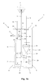
- Fig. 3 shows a first embodiment of a laser distance meter 60 according to the invention for electro-optical measurement of the distance of the target object 4 to a reference mark.
- the laser distance meter 60 has, in addition to the measuring device 41 in coaxial construction and the display and control devices 6, 7 on an optical target device 61 .
- the laser distance meter 60 differs in structure of the optical aiming device 61 from the in Fig. 1a illustrated laser distance meter 1, otherwise constructed analog.
- the measuring device 41 comprises in addition to the transmitting device 43 with the beam source 21 and the beam shaping optics 44, the receiving device 45 with the detector 24 and the beam shaping optics 44, the evaluation device 26 and the beam splitter 46.
- the laser beam strikes after the exit from the beam source 21 to the beam splitter
- the beam source 21 is, for example, a semiconductor laser which generates a laser beam in the visible spectrum, for example a red laser beam with a wavelength of 635 nm, or another laser with a suitable wavelength and power.
- the laser beam leaves the beam source 21 at an opening at which the laser beam is diffracted. Due to the diffraction and divergence, the laser beam expands.
- the laser beam is collimated using the beam-shaping optical system 44 or focused on the target object 4.
- the detector 24 is, for example, a photodiode or another receiver adapted to the wavelength and the power of the beam source 21.
- the received beam 5 reflected or scattered by the target object 4 is focused onto the detector 24 with the aid of the beam shaping optics 44.
- the evaluation device 26 is connected to the detector 24 and the beam source 21 via the communication links 27a, 27b and determines the distance value to the target object 4 from the time difference between the laser beam emitted by the beam source and the received beam detected by the detector 24 Evaluation device 26 with the display device 6, which indicates the measured distance value connected.
- the optical sighting device 61 comprises a first optical element 62 and a second optical element 63rd
- the user sees through the sight 31 in the side surface 14 in the optical target device 61. He looks at the first optical element 62.
- the first optical element 62 is formed as a beam splitter and in the beam path of the decoupled from the measuring device 41 laser beam at 45 ° inclination arranged to the optical axis.
- the laser beam 64 coupled out of the measuring device 41 via the beam-shaping optical system 44 strikes the first optical element 62 of the optical target device 61, which is designed to be predominantly reflective for the laser wavelength (eg reflectance R ⁇ 95%), so that the predominant part of the laser beam 64 as reflected laser beam 65 leaves the laser distance meter 60 via an outlet opening 66 in the side surface 15 and a small part as a transmitted laser beam 67 passes through the first optical element 62 therethrough.
- the second optical element 63 is arranged, which is formed predominantly reflective for the laser wavelength ⁇ .
- the transmitted laser beam 67 is reflected on the second optical element 63 in itself and strikes the first optical element 62.
- the major part of the laser beam 67 is deflected as a reflected laser beam 68 in the direction of the sight 31.
- the reflected laser beam 68 appears to the user as a sharp point of light and shows him the exact position of the laser beam 65 on the target object 4.
- the laser beam 65 which has leaked out of the laser distance meter 60 via the outlet opening 66, strikes the target object 4. A part of the laser beam 65 is reflected at the target object 4 and a part is diffusely scattered. The reflected laser beam and a part of the scattered laser beam enter the laser distance meter 60 as the receiving beam 69 via the exit opening 66.
- the reception beam 69 strikes the first optical element 62, which is predominantly reflective for a narrow wavelength range ⁇ ⁇ around the laser wavelength ⁇ and predominantly transmissive for other wavelengths.
- the majority of the receive beam 69 is deflected as a reflected receive beam 70 in the direction of the beam shaping optics 44, strikes the beam shaping optics 44 and is focused in the direction of the beam splitter 46 and via the beam splitter 46 imaged on the detector 24.
- the ambient light with the target image passes through the first optical element 62 up to a narrow wavelength range around the laser wavelength ⁇ and reaches the eye of the user via the sight 31.
- the user sees the target image together with the light spot of the reflected laser beam 68 located in the target image at the same position as the laser beam on the target 4.
- the transmission and reflection levels of the first optical element 62 and the second optical element 63 of the optical target device 61 are adjusted so that the power reaching the eye of the user is very strongly attenuated, to prevent damage to the eye and an over-radiation of the target image.
- a filter can be used which attenuates the power of the laser beam 68.
- the sight 31 and the outlet opening 66 for the laser beam 65 are arranged on the opposite side surfaces 14, 15 of the housing 9.
- the direction in which the user looks in the sight 31 is indicated by a direction vector (arrow 71 ).
- the direction 71 in which the user looks into the sighting device 31 of the optical sighting device is aligned coaxially with the optical axis of the laser beam coupled out of the laser distance measuring device 60 via the outlet opening 66. Due to the coaxial arrangement, the user sees in the propagation direction of the laser beam.
- the stabilization system of the human eye-brain complex allows easy and accurate alignment and positioning of the laser beam on the target.
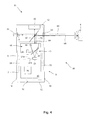
- Fig. 4 shows a second embodiment of a laser distance meter 80 according to the invention for electro-optical measurement of the distance of the target object 4 to a reference mark, which differs from the first embodiment 60 of a laser distance meter according to the invention by the construction of the optical target device 81 , otherwise constructed analogously.
- the laser distance measuring device 80 comprises, in addition to the optical aiming device 81, the measuring, display and operating devices 41, 6, 7 which are also contained in the laser distance measuring device 60.
- the optical aiming device 81 consists of two optical elements, the first optical element 62 and a second optical element 82.
- the first optical element 62 is a high reflectivity beam splitter (e.g., R ⁇ 95%) for the laser wavelength ⁇ and a high transmittance formed for all other wavelengths of the visible spectrum.
- the predominant part of the laser beam 64 coupled out of the measuring device 41 via the beam-shaping optical system 44 is deflected on the first optical element 62 as a reflected laser beam 65 in the direction of the target object 4.
- the reception beam 69 strikes the first optical element 62, at which the predominant part of the reception beam 69 is deflected as a reflected reception beam 70 in the direction of the measuring device 41.
- the image of the target 4, as described for the laser distance meter 60, reaches the user's eye via the first optical element 62.
- a field distribution is generated by the second optical element 82, which is reflected via the first optical element 62 in the direction of the sight 31.
- the user perceives this field distribution as a sharp point of light, which is located at the same position in the image of the target object 4 as the laser beam on the target object 4, so that an accurate positioning of the laser beam on the target object 4 is possible.
- the user sees additional information through this field distribution, such as the distance measured value in the target object image.
- the second optical element 82 is connected via a communication link 83 to the evaluation device 26 of the measuring device 41.
- the second optical element 82 of the optical target device 81 consists of a microdisplay whose display is transformed into infinity via a lens. This transformed image is perceived by the user as a display content.
Landscapes
- Engineering & Computer Science (AREA)
- Computer Networks & Wireless Communication (AREA)
- Physics & Mathematics (AREA)
- General Physics & Mathematics (AREA)
- Radar, Positioning & Navigation (AREA)
- Remote Sensing (AREA)
- Optical Radar Systems And Details Thereof (AREA)
- Measurement Of Optical Distance (AREA)
- Length Measuring Devices By Optical Means (AREA)
Abstract
Description
- Die vorliegende Erfindung betrifft ein Lasergerät zur elektrooptischen Messung der Distanz eines Zielobjekts zu einer Referenzmarke bestehend aus einem Gehäuse, wobei das Gehäuse eine Austrittsöffnung zum Auskoppeln eines Laserstrahls aus dem Lasergerät aufweist, einer Messeinrichtung, die den Laserstrahl aussendet und aus dem von dem Zielobjekt kommenden Empfangsstrahl einen Distanzwert ermittelt, einer Anzeigeeinrichtung zur Anzeige des Distanzwertes, einer Bedieneinrichtung zur Bedienung des Lasergerätes und zum Start der Distanzmessung und einer optischen Zieleinrichtung zur Ausrichtung des Laserstrahls auf das Zielobjekt.
- Lasergeräte zur elektrooptischen Distanzmessung sind aus dem Stand der Technik bekannt und werden kommerziell vertrieben. Diese Laserdistanzmessgeräte senden einen modulierten Laserstrahl aus, der auf die Oberfläche eines Zielobjektes, dessen Distanz zum Lasergerät zu ermitteln ist, ausgerichtet ist. Das Licht des von der Oberfläche des Zielobjektes reflektierten oder gestreuten Laserstrahls, im Folgenden Empfangsstrahl genannt, wird vom Laserdistanzmessgerät detektiert und zur Ermittlung der Distanz verwendet. Der Anwendungsbereich derartiger Laserdistanzmessgeräte umfasst in der Regel Entfernungen von einigen Zentimetern bis zu einigen hundert Metern.
- Die aus dem Stand der Technik bekannten Laserdistanzmessgeräte lassen sich entsprechend der Anordnung der Sende- und Empfangseinrichtungen in zwei Kategorien unterteilen, in biaxiale Anordnungen, bei denen die optischen Achsen der Sende- und Empfangseinrichtungen parallel versetzt zueinander verlaufen, und koaxiale Anordnungen, bei denen die optischen Achsen der Sende- und Empfangseinrichtungen übereinander liegen. Biaxiale Anordnungen haben den Vorteil, dass keine Strahlteilung zur Trennung des ausgesandten Laserstrahls und des vom Zielobjekt kommenden Empfangsstrahls erforderlich ist und dass Sende- und Empfangszweig gut voneinander separierbar sind, wodurch optisches Übersprechen weitgehend vermeidbar ist. Allerdings besteht unter anderem der Nachteil, dass es im Bereich kurzer Entfernungen aufgrund einer Parallaxe zu Detektionsproblemen kommen kann: Die Abbildung des Zielobjektes auf die Detektoroberfläche verschiebt sich mit abnehmender Entfernung von der optischen Achse der Empfangseinrichtung weg und erfährt außerdem eine Variation des Strahlquerschnittes in der Detektorebene. Koaxiale Anordnungen besitzen den Vorteil der Parallaxefreiheit und des kostengünstigeren Aufbaus. Der Nachteil ist aber das nicht vermeidbare optische Übersprechen von der Sendeeinheit zur Empfangseinheit, da für beide Einheiten derselbe optische Kanal verwendet wird. Das optische Übersprechen führt zu einem zyklischen Distanzmessfehler.
- Im Baugewerbe werden Laserdistanzmessgeräte unter anderem zur Distanzmessung in Innenräumen eingesetzt, in denen der Laserstrahl auch über große Distanzen (> 50 m) mit dem bloßen Auge wahrgenommen werden kann. Wenn man jedoch beim Außeneinsatz auf Zielobjekte mit hoher Umfeldleuchtdichte zielt, wie bspw. eine sonnenbeschienene Wand, ist der Laserstrahl auf dem Zielobjekt nur schwer oder überhaupt nicht mehr zu sehen. Zur Verbesserung der Sichtbarkeit wäre eine Erhöhung der Laserleistung denkbar. Höhere Laserleistungen sind jedoch aus Sicherheitsgründen nicht zulässig. Die maximale Leistung eines Laserdistanzmessgerätes ist durch die Laserklasse festgelegt. Bei Lasern der Klasse 2, die die bekannten Laserdistanzmessgeräte umfasst, darf eine maximale Leistung von 1 mW nicht überschritten werden. Um die Position des Laserstrahls auf dem Zielobjekt für den Anwender sichtbar zu machen, werden Laserdistanzmessgeräte mit einer optischen Zieleinrichtung ausgestattet.
-
Fig. 1a zeigt ein bekanntes Lasergerät 1 zur elektrooptischen Distanzmessung, im Folgenden als Laserdistanzmessgerät 1 bezeichnet, mit einer Messeinrichtung 2, die einen Laserstrahl 3 auf ein Zielobjekt 4 ausrichtet und aus dem Licht des vom Zielobjekt 4 reflektierten oder gestreuten Laserstrahls, das als Empfangsstrahl 5 bezeichnet wird, einen Distanzwert ermittelt, mit einer Anzeigeeinrichtung 6 zur Anzeige des Distanzwertes sowie einer Bedieneinrichtung 7 zur Bedienung des Laserdistanzmessgerätes 1 und zum Starten der Distanzmessung. Das Laserdistanzmessgerät 1 weist außerdem eine optische Zieleinrichtung 8 auf, die die Distanzmessung besonders bei Außenmessungen oder bei schlechten Sichtverhältnissen erleichtern soll, wenn der Laserstrahl 3 mit bloßem Auge auf dem Zielobjekt 4 schlecht oder nicht mehr sichtbar ist. - Das Laserdistanzmessgerät 1 ist von einem Gehäuse 9 umgeben. Die Anzeige- und Bedieneinrichtungen 6, 7 sind in eine Oberseite 10 des Gehäuses 9 eingebettet. Um einen hohen Bedienkomfort bei der Bedienung des Laserdistanzmessgerätes 1 und der Anzeige des Distanzwertes zu gewährleisten, sind die Oberseite 10 und die der Oberseite 10 gegenüberliegende Unterseite 11 des Gehäuses 9 die beiden größten Gehäuseflächen des Laserdistanzmessgerätes 1. Die an die Oberseite 10 angrenzenden Vorder- und Hinterseiten 12, 13 sowie die Seitenflächen 14, 15 des Gehäuses 9 sind möglichst klein ausgebildet, um ein handliches Laserdistanzmessgerät 1 aufzubauen.
- Der Austritt des Laserstrahls 3 aus dem Gehäuse 9 erfolgt über eine Austrittsöffnung 16, die an der Vorderseite 12 des Gehäuses 9 angeordnet ist, wobei die optische Achse des Laserstrahls 3 senkrecht zur Vorderseite 12 ausgerichtet ist. Der vom Zielobjekt 4 kommende Empfangsstrahl 5 tritt über eine Eintrittsöffnung 17 in das Laserdistanzmessgerät 1 ein.
- Die Distanzmessung zu dem Zielobjekt 4 erfolgt in Bezug auf eine am Laserdistanzmessgerät befindliche Referenzmarke. Bei dem bekannten Laserdistanzmessgerät 1 werden die Vorderseite 12, die Hinterseite 13, eine Anschlagspitze 18 oder Messverlängerungen (nicht gezeigt) als Referenzmarken verwendet. Die Umschaltung zwischen den Referenzmarken erfolgt über eine Umschalteinrichtung 19 oder automatisch, bspw. wenn die Anschlagspitze 18 um 180° ausgeklappt ist.
-
Fig. 1b zeigt das bekannte Laserdistanzmessgerät 1 derFig. 1a in einer Ansicht von innen mit der Messeinrichtung 2 und der optischen Zieleinrichtung 8. Die Messeinrichtung 2 umfasst eine Sendeeinrichtung 20 mit einer Strahlquelle 21 und einer ersten Strahlformungsoptik 22, eine Empfangseinrichtung 23 mit einem Detektor 24 und einer zweiten Strahlformungsoptik 25 sowie eine Auswerteeinrichtung 26. Die Sende- und Empfangseinrichtungen 20, 23 sind biaxial angeordnet, d.h. ihre optischen Achsen verlaufen parallel zueinander, fallen aber nicht zusammen. Die Auswerteeinrichtung 26 ist über Kommunikationsverbindungen 27a, 27b, 28 mit dem Detektor 24, der Strahlquelle 21 und der Anzeigeeinrichtung 6 verbunden. Sie bestimmt aus der Zeitdifferenz zwischen dem von der Strahlquelle 21 ausgesandten Laserstrahl 3 und dem vom Detektor 24 erfassten Empfangsstrahl 5 den Distanzwert zum Zielobjekt 4. - Die optische Zieleinrichtung 8 weist ein erstes optisches Element 29 und ein zweites optisches Element 30 auf. Der Anwender sieht über einen Visiereinblick 31, der in der Seitenfläche 14 des Gehäuses 9 angeordnet ist, in die optische Zieleinrichtung 8. Dabei sieht der Anwender auf das zweite optische Element 30. Das vom Zielobjekt 4 kommende Umgebungslicht 32 tritt mit dem Bild des Zielobjektes 4 über eine Eintrittsöffnung 33 in der Vorderseite 12 in die optische Zieleinrichtung 8 ein und trifft auf das erste optische Element 29. Von dort wird es in Richtung des zweiten optischen Elements 30 abgelenkt. Dadurch, dass das Bild des Zielobjektes 4 zweifach an dem ersten und zweiten optischen Element 29, 30 reflektiert wird, entsteht ein aufrecht stehendes, seitenrichtiges Bild des Zielobjektes 4, welches vom Anwender im Visiereinblick 31 wahrgenommen wird.
- Im Strahlengang des aus der Messeinrichtung 2 ausgekoppelten Laserstrahls 34 ist ein Strahlteiler 35 angeordnet, der vorzugsweise unter 45° zur optischen Achse des Laserstrahls 34 geneigt ist. Der Strahlteiler 35 ist so ausgebildet, dass der überwiegende Teil des Laserstrahls (z.B. Reflexionsgrad R ≥ 95 %) als transmittierter Laserstrahl 36 durch den Strahlteiler 35 hindurch tritt, während der übrige Teil (z.B. 5 %) als reflektierter Laserstrahl 37 abgelenkt wird. Der reflektierte Laserstrahl 37 durchdringt das zweite optische Element 30 der optischen Zieleinrichtung 8 und kann vom Anwender als heller, nahezu punktförmiger Lichtfleck wahrgenommen werden. Das zweite optische Element 30 ist so ausgebildet, dass es für die Laserwellenlänge λ transmittierend und für den Wellenlängenbereich des vom Zielobjekt 4 ausgehenden Umgebungslichts bis auf einen schmalen Bereich um die Laserwellenlänge λ überwiegend reflektierend ist. Der Anwender sieht beim Blick in die optische Zieleinrichtung 8 das Bild des Zielobjektes 4 und den Lichtfleck des reflektierten Laserstrahls 37, der sich an derselben Position im Bild des Zielobjektes 4 befindet, wie der Laserstrahl 3 auf der Oberfläche des Zielobjektes 4. Über die Positionierung des aus dem reflektierten Laserstrahl 37 resultierenden Lichtpunktes im Bild des Zielobjektes 4 erfolgt die genaue Positionierung des Laserstrahls 3 auf der Oberfläche des Zielobjektes 4.
-
Fig. 2 zeigt ein weiteres bekanntes Laserdistanzmessgerät 40 mit einer Messeinrichtung 41 in koaxialem Aufbau und einer optischen Zieleinrichtung 42. Die Messeinrichtung 41 umfasst eine Sendeeinrichtung 43 mit der Strahlquelle 21 und einer Strahlformungsoptik 44, eine Empfangseinrichtung 45 mit dem Detektor 24 und der Strahlformungsoptik 44, die Auswerteeinrichtung 26 sowie einen Strahlteiler 46. Die Sende- und Empfangseinrichtungen 43, 45 sind koaxial angeordnet, d.h. ihre optischen Achsen fallen zusammen. Die Strahlformungsoptik 44 ist ein gemeinsames optisches Element der Sende- und Empfangseinrichtungen 43, 45. Sie ist derart ausgebildet, dass der aus der Strahlquelle 21 ausgekoppelte Laserstrahl kollimiert bzw. auf das Zielobjekt 4 fokussiert und der vom Zielobjekt 4 kommende Empfangsstrahl über den Strahlteiler 46 auf den Detektor 24 fokussiert wird. Mit Hilfe des Strahlteilers 46 wird der aus der Strahlquelle 21 ausgekoppelte Laserstrahl von dem Empfangsstrahl, der vom Zielobjekt 4 reflektiert oder gestreut wird und von dem Detektor 24 erfasst werden soll, getrennt. Der Strahlteiler 46 ist so ausgebildet, dass er für Licht mit der Wellenlänge λ und Polarisationsrichtung des Laserstrahls transmittierend und für Licht mit einer zur Polarisationsrichtung des Laserstrahls senkrechten Polarisationsrichtung reflektierend ausgebildet ist. - Die optische Zieleinrichtung 42 umfasst drei optische Elemente, ein erstes optisches Element 47, ein zweites optisches Element 48 und ein drittes optisches Element 49. Das erste und dritte optische Element 47, 49 sind für einen schmalen Wellenlängenbereich um die Laserwellenlänge λ überwiegend transmittierend und für andere Wellenlängen des sichtbaren Spektralbereiches überwiegend reflektierend ausgebildet. Das zweite optische Element 48 ist für alle Wellenlängen des sichtbaren Spektralbereichs überwiegend reflektierend ausgebildet. Der Anwender sieht über den Visiereinblick 31 in der Seitenfläche 14 des Gehäuses 9 in die optische Zieleinrichtung 42. Dabei sieht er auf das zweite optische Element 48.
- Der über die Strahlformungsoptik 44 aus der Messeinrichtung 41 ausgekoppelte Laserstrahl 50 tritt überwiegend (z.B. 95 %) durch das erste optische Element 47 hindurch und trifft auf das dritte optische Element 49, an dem der überwiegende Teil (z.B. 95 %) als transmittierter Laserstrahl 51 hindurch tritt und das Laserdistanzmessgerät 40 über eine Austrittsöffnung 52 in der Vorderseite 12 verlässt, während ein kleiner Teil (z.B. 5 %) als reflektierter Laserstrahl 53 in Richtung des ersten optischen Elementes 47 reflektiert wird. Der reflektierte Laserstrahl 53 wird am ersten optischen Element 47 zu einem kleinen Teil (z.B. 5 %) in Richtung des zweiten optischen Elementes 48 reflektiert und von dort als reflektierter Laserstrahl 54 in Richtung des Visiereinblicks 31 abgelenkt. Der in den Visiereinblick 31 schauende Anwender nimmt den Laserstrahl 34 als scharfen Lichtpunkt wahr.
- Das vom Zielobjekt 4 kommende Umgebungslicht 55 tritt als Zielobjektbild durch die Austrittsöffnung 52 in das Laserdistanzmessgerät 40 ein und trifft auf das dritte optische Element 49, durch das das Zielobjektbild 55 überwiegend hindurch tritt. Das transmittierte Zielobjektbild 56 trifft auf das erste optische Element 47, wird als reflektiertes Zielobjektbild 57 in Richtung des zweiten optischen Elementes 48 abgelenkt und von dort als Zielobjektbild 58 weiter Richtung Visiereinblick 31 reflektiert. Der Anwender sieht den Lichtpunkt des eingespiegelten Laserstrahls zusammen mit dem Zielobjektbild und kann auf diese Weise den Laserstrahl auf dem Zielobjekt positionieren.
- Bei allen bekannten Laserdistanzmessgeräten befindet sich die Austrittsöffnung für den Laserstrahl in der Vorderseite des Gehäuses und der Visiereinblick der optischen Zieleinrichtung ist in einer Seitenfläche des Gehäuses angeordnet, so dass die Justierung des Laserstrahls mit Hilfe der optischen Zieleinrichtung senkrecht zur optischen Achse des aus dem Gehäuse ausgekoppelten Laserstrahls "quasi über Eck" erfolgt. Die Justierung über Eck bereitet vor allem dem ungeübten Anwender Probleme. Das Stabilisierungssystem des menschlichen Auge-Gehirn-Komplexes arbeitet besonders gut, wenn die Justierung parallel zur Ausbreitungsrichtung des ausgekoppelten Laserstrahls erfolgt. Dazu müsste der Visiereinblick bei den bekannten Laserdistanzmessgeräten in der Hinterseite des Gehäuses angeordnet sein. Da sich im Inneren des Laserdistanzmessgerätes neben der Messeinrichtung weitere Komponenten befinden, ist es aus Platzgründen schwierig, zwischen dem Visiereinblick einer optischen Zieleinrichtung in der Hinterseite und der Austrittsöffnung für den Laserstrahl in der Vorderseite einen Strahlengang aufzubauen.
- Die Aufgabe der vorliegenden Erfindung besteht demgegenüber darin, ein Lasergerät zur elektrooptischen Distanzmessung bereitzustellen, das auch für ungeübte Anwender eine einfache Ausrichtung des Laserstrahls auf das Zielobjekt mit Hilfe einer optischen Zieleinrichtung erlaubt.
- Diese Aufgabe wird bei dem eingangs genannten Lasergerät zur elektrooptischen Distanzmessung erfindungsgemäß dadurch gelöst, dass die Richtung, in die ein Anwender in die optischen Zieleinrichtung schaut, parallel, bevorzugt koaxial, zur optischen Achse des über die Austrittsöffnung aus dem Lasergerät ausgekoppelten Laserstrahls ausgerichtet ist. Bei einem derartigen Laserdistanzmessgerät sieht der Anwender in die Ausbreitungsrichtung des Laserstrahls. Das Stabilisierungssystem des menschlichen Auge-Gehirn-Komplexes ermöglicht eine einfache und genaue Ausrichtung und Positionierung des Laserstrahls auf dem Zielobjekt.
- In einer bevorzugten Ausführung weist die optische Zieleinrichtung einen Visiereinblick auf, wobei der Visiereinblick und die Austrittsöffnung in gegenüberliegenden Flächen des Gehäuses angeordnet sind. Dabei ist der Visiereinblick besonders bevorzugt in der Oberseite, in der der Oberseite gegenüberliegenden Unterseite oder in einer der Seitenflächen des Gehäuses angeordnet.
- In einer bevorzugten Ausführung ist eine Umlenkoptik vorgesehen, die den aus der Messeinrichtung ausgekoppelten Laserstrahl in Richtung der Austrittsöffnung umlenkt. Dabei ist die Umlenkoptik für einen schmalen Bereich um die Wellenlänge des Laserstrahls λ ± Δλ, mit Δλ = 10 µm besonders bevorzugt überwiegend reflektierend und für andere Wellenlängenbereiche, insbesondere für das vom Zielobjekt kommende Umgebungslichts, transmittierend ausgebildet.
- In einer bevorzugten Ausführung bildet die Umlenkoptik gleichzeitig ein erstes optisches Element der optischen Zieleinrichtung.
- In einer bevorzugten Ausführung weist die optische Zieleinrichtung ein zweites optisches Element, das für einen schmalen Bereich um die Wellenlänge des Laserstrahls λ ± Δλ, mit Δλ = 10 µm überwiegend reflektierend ausgebildet ist, auf.
- Besonders bevorzugt ist das zweite optische Element über eine Kommunikationsverbindung mit einer Auswerteeinrichtung der Messeinrichtung verbunden und stellt dem Anwender Zusatzinformationen, bspw. in Form eines Lichtpunktes oder des Distanzwertes, im Zielobjektbild zur Verfügung.
- Weitere Vorteile und vorteilhafte Ausgestaltungen des Gegenstands der Erfindung sind der Beschreibung, der Zeichnung und den Ansprüchen entnehmbar. Ebenso können die vorstehend genannten und die noch weiter aufgeführten Merkmale erfindungsgemäß jeweils einzeln für sich oder zu mehreren in beliebigen Kombinationen Verwendung finden. Die gezeigten und beschriebenen Ausführungsformen sind nicht als abschließende Aufzählung zu verstehen, sondern haben vielmehr beispielhaften Charakter für die Schilderung der Erfindung.
- Es zeigen:
- Fign. 1a,b
- ein bekanntes Laserdistanzmessgerät in einer Ansicht von außen (
Fig. 1a ) und einer Ansicht von innen (Fig. 1 b) ; - Fig. 2
- eine weiteres bekanntes Laserdistanzmessgerät;
- Fig. 3
- eine erste Ausführungsform eines erfindungsgemäßen Laserdistanzmessge- räts mit einer optischen Zieleinrichtung; und
- Fig. 4
- eine zweite Ausführungsform eines erfindungsgemäßen Laserdistanzmessge- räts mit einer optischen Zieleinrichtung.
- Gleiche oder funktionsgleiche Elemente werden durch gleiche Bezugszeichen in den Figuren indiziert, soweit nicht anders angegeben.
-
Fig. 3 zeigt eine erste Ausführungsform eines erfindungsgemäßen Laserdistanzmessgeräts 60 zur elektrooptischen Messung der Distanz des Zielobjektes 4 zu einer Referenzmarke. Das Laserdistanzmessgerät 60 weist neben der Messeinrichtung 41 in koaxialem Aufbau und den Anzeige- und Bedieneinrichtungen 6, 7 eine optische Zieleinrichtung 61 auf. Das Laserdistanzmessgerät 60 unterscheidet sich im Aufbau der optischen Zieleinrichtung 61 von dem inFig. 1a dargestellten Laserdistanzmessgerät 1, ist ansonsten analog aufgebaut. - Die Messeinrichtung 41 umfasst neben der Sendeeinrichtung 43 mit der Strahlquelle 21 und der Strahlformungsoptik 44, der Empfangseinrichtung 45 mit dem Detektor 24 und der Strahlformungsoptik 44, die Auswerteeinrichtung 26 und den Strahlteiler 46. Der Laserstrahl trifft nach dem Austritt aus der Strahlquelle 21 auf den Strahlteiler 46 und anschließend auf die Strahlformungsoptik 44. Die Strahlquelle 21 ist bspw. ein Halbleiterlaser, der einen Laserstrahl im sichtbaren Spektrum, bspw. einen roten Laserstrahl mit einer Wellenlänge von 635 nm, erzeugt oder ein anderer Laser mit einer geeigneten Wellenlänge und Leistung. Der Laserstrahl verlässt die Strahlquelle 21 an einer Öffnung, an der der Laserstrahl gebeugt wird. Aufgrund der Beugung und Divergenz kommt es zu einer Aufweitung des Laserstrahls. Um den Strahldurchmesser des Laserstrahls 3 auf dem Zielobjekt 4 zu begrenzen, wird der Laserstrahl mit Hilfe der Strahlformungsoptik 44 kollimiert oder auf das Zielobjekt 4 fokussiert. Der Detektor 24 ist bspw. eine Fotodiode oder ein anderer an die Wellenlänge und die Leistung der Strahlquelle 21 angepasster Empfänger. Der vom Zielobjekt 4 reflektierte oder gestreute Empfangsstrahl 5 wird mit Hilfe der Strahlformungsoptik 44 auf den Detektor 24 fokussiert. Die Auswerteeinrichtung 26 ist über die Kommunikationsverbindungen 27a, 27b mit dem Detektor 24 und der Strahlquelle 21 verbunden und bestimmt aus der Zeitdifferenz zwischen dem von der Strahlquelle ausgesandten Laserstrahl und dem vom Detektor 24 erfassten Empfangsstrahl den Distanzwert zum Zielobjekt 4. Über die Kommunikationsverbindung 28 ist die Auswerteeinrichtung 26 mit der Anzeigeeinrichtung 6, die den gemessenen Distanzwert anzeigt, verbunden.
- Die optische Zieleinrichtung 61 weist ein erstes optisches Element 62 und ein zweites optisches Element 63 auf. Der Anwender sieht über den Visiereinblick 31 in der Seitenfläche 14 in die optische Zieleinrichtung 61. Dabei sieht er auf das erste optische Element 62. Das erste optische Element 62 ist als Strahlteiler ausgebildet und im Strahlengang des aus der Messeinrichtung 41 ausgekoppelten Laserstrahls unter 45° Neigung zur optischen Achse angeordnet.
- Der aus der Messeinrichtung 41 über die Strahlformungsoptik 44 ausgekoppelte Laserstrahl 64 trifft auf das erste optische Element 62 der optischen Zieleinrichtung 61, das für die Laserwellenlänge überwiegend reflektierend ausgebildet ist (z.B. Reflexionsgrad R ≥ 95 %), so dass der überwiegende Teil des Laserstrahls 64 als reflektierter Laserstrahl 65 das Laserdistanzmessgerät 60 über eine Austrittsöffnung 66 in der Seitenfläche 15 verlässt und ein geringer Teil als transmittierter Laserstrahl 67 durch das erste optische Element 62 hindurch tritt. Im Strahlengang des transmittierten Laserstrahls 67 ist das zweite optische Element 63 angeordnet, das für die Laserwellenlänge λ überwiegend reflektierend ausgebildet ist. Der transmittierte Laserstrahl 67 wird am zweiten optischen Element 63 in sich selbst reflektiert und trifft auf das erste optische Element 62. Dort wird der überwiegende Teil des Laserstrahls 67 als reflektierter Laserstrahl 68 in Richtung des Visiereinblicks 31 abgelenkt. Der reflektierte Laserstrahl 68 erscheint dem Anwender als scharfer Lichtpunkt und zeigt ihm die genaue Position des Laserstrahls 65 auf dem Zielobjekt 4 an.
- Der über die Austrittsöffnung 66 aus dem Laserdistanzmessgerät 60 ausgetretene Laserstrahl 65 trifft auf das Zielobjekt 4. Am Zielobjekt 4 wird ein Teil des Laserstrahls 65 reflektiert und ein Teil diffus gestreut. Der reflektierte Laserstrahl und ein Teil des gestreuten Laserstrahls treten als Empfangsstrahl 69 über die Austrittsöffnung 66 in das Laserdistanzmessgerät 60 ein. Der Empfangsstrahl 69 trifft auf das erste optische Element 62, das für einen schmalen Wellenlängenbereich ±Δλ um die Laserwellenlänge λ herum überwiegend reflektierend und für andere Wellenlängen überwiegend transmittierend ausgebildet ist. Am ersten optischen Element 62 wird der überwiegende Teil des Empfangsstrahls 69 als reflektierter Empfangsstrahl 70 in Richtung der Strahlformungsoptik 44 abgelenkt, trifft auf die Strahlformungsoptik 44 und wird in Richtung des Strahlteilers 46 fokussiert und über den Strahlteiler 46 auf den Detektor 24 abgebildet. Das Umgebungslicht mit dem Zielobjektbild tritt bis auf einen schmalen Wellenlängenbereich um die Laserwellenlänge λ herum durch das erste optische Element 62 hindurch und erreicht über den Visiereinblick 31 das Auge des Anwenders. Der Anwender sieht das Zielobjektbild zusammen mit dem Lichtpunkt des reflektierten Laserstrahls 68, der sich im Zielobjektbild an derselben Position befindet wie der Laserstrahl auf dem Zielobjekt 4.
- Da der Anwender direkt in den Laserstrahl 68 schaut, sind die Transmissions- und Reflexionsgrade des ersten optischen Elementes 62 und des zweiten optischen Elementes 63 der optischen Zieleinrichtung 61 so angepasst, dass die Leistung, die das Auge des Anwenders erreicht, sehr stark gedämpft wird, um eine Schädigung des Auges sowie eine Überstrahlung des Zielobjektbildes zu verhindern. Alternativ kann ein Filter eingesetzt werden, der die Leistung des Laserstrahls 68 abschwächt.
- Der Visiereinblick 31 und die Austrittsöffnung 66 für den Laserstrahl 65 sind auf den gegenüberliegenden Seitenflächen 14, 15 des Gehäuses 9 angeordnet. Die Richtung, in der der Anwender in den Visiereinblick 31 schaut, wird durch einen Richtungsvektor (Pfeil 71) angezeigt. Die Richtung 71, in die der Anwender in den Visiereinblick 31 der optischen Zieleinrichtung schaut, ist koaxial zur optischen Achse des über die Austrittsöffnung 66 aus dem Laserdistanzmessgerät 60 ausgekoppelten Laserstrahls ausgerichtet. Durch die koaxiale Anordnung sieht der Anwender in die Ausbreitungsrichtung des Laserstrahls. Das Stabilisierungssystem des menschlichen Auge-Gehirn-Komplexes ermöglicht eine einfache und genaue Ausrichtung und Positionierung des Laserstrahls auf dem Zielobjekt.
-
Fig. 4 zeigt eine zweite Ausführungsform eines erfindungsgemäßen Laserdistanzmessgeräts 80 zur elektrooptischen Messung der Distanz des Zielobjektes 4 zu einer Referenzmarke, das sich durch den Aufbau der optischen Zieleinrichtung 81 von der ersten Ausführungsform 60 eines erfindungsgemäßen Laserdistanzmessgeräts unterscheidet, ansonsten analog aufgebaut ist. - Das Laserdistanzmessgerät 80 umfasst neben der optischen Zieleinrichtung 81 die Mess-, Anzeige- und Bedieneinrichtungen 41, 6, 7, die auch im Laserdistanzmessgerät 60 enthalten sind. Die optische Zieleinrichtung 81 besteht aus zwei optischen Elementen, dem ersten optischen Element 62 und einem zweiten optischen Element 82. Das erste optische Element 62 ist als Strahlteiler mit einem hohen Reflexionsgrad (bspw. R ≥ 95 %) für die Laserwellenlänge λ und einem hohen Transmissionsgrad für alle anderen Wellenlängen des sichtbaren Spektrums ausgebildet.
- Der überwiegende Teil des aus der Messeinrichtung 41 über die Strahlformungsoptik 44 ausgekoppelten Laserstrahls 64 wird am ersten optischen Element 62 als reflektierter Laserstrahl 65 in Richtung Zielobjekt 4 abgelenkt. Der Empfangsstrahl 69 trifft auf das erste optische Element 62, an dem der überwiegende Teil des Empfangsstrahls 69 als reflektierter Empfangsstrahl 70 in Richtung der Messeinrichtung 41 abgelenkt wird. Das Bild des Zielobjektes 4 erreicht, wie für das Laserdistanzmessgerät 60 beschrieben, über das erste optische Element 62 das Auge des Anwenders. Des Weiteren wird vom zweiten optischen Element 82 eine Feldverteilung erzeugt, die über das erste optische Element 62 in Richtung des Visiereinblicks 31 reflektiert wird. Der Anwender nimmt diese Feldverteilung einerseits als scharfen Lichtpunkt wahr, der sich an derselben Position im Bild des Zielobjektes 4 befindet wie der Laserstrahl auf dem Zielobjekt 4, so dass eine genaue Positionierung des Laserstrahls auf dem Zielobjekt 4 möglich ist. Andererseits sieht der Anwender durch diese Feldverteilung Zusatzinformationen, wie z.B. den Distanzmesswert im Zielobjektbild. Das zweite optische Element 82 ist über eine Kommunikationsverbindung 83 mit der Auswerteeinrichtung 26 der Messeinrichtung 41 verbunden.
- Das zweite optische Element 82 der optischen Zieleinrichtung 81 besteht aus einem Mikrodisplay, dessen Anzeige über eine Linse in Unendliche transformiert wird. Dieses transformierte Bild wird vom Anwender als Anzeigeinhalt wahrgenommen.
Claims (11)
- Lasergerät (60; 80) zur elektrooptischen Messung der Distanz eines Zielobjektes (4) zu einer Referenzmarke (10-15, 18) bestehend aus einem Gehäuse (9), wobei das Gehäuse (9) eine Austrittsöffnung (66) zum Auskoppeln eines Laserstrahls (65) aus dem Lasergerät (60; 80) aufweist, einer Messeinrichtung (41), die einen Laserstrahl (64) aussendet und aus dem von dem Zielobjekt (4) kommenden Empfangsstrahl (69) einen Distanzwert ermittelt, einer Anzeigeeinrichtung (6) zur Anzeige des Distanzwertes, einer Bedieneinrichtung (7) zur Bedienung des Lasergerätes und zum Start der Distanzmessung und einer optischen Zieleinrichtung (61; 81) zur Ausrichtung des Laserstrahls (65) auf das Zielobjekt (4),
dadurch gekennzeichnet, dass
die Richtung (71), in die ein Anwender in die optische Zieleinrichtung (61; 81) schaut, parallel zur optischen Achse des über die Austrittsöffnung (66) aus dem Lasergerät (60; 80) ausgekoppelten Laserstrahls (65) ausgerichtet ist. - Lasergerät nach Anspruch 1, dadurch gekennzeichnet, dass die Richtung (71), in die der Anwender in die optische Zieleinrichtung (61; 81) schaut, koaxial zur optischen Achse des ausgekoppelten Laserstrahls (65) ausgerichtet ist.
- Lasergerät nach Anspruch 1, dadurch gekennzeichnet, dass die optische Zieleinrichtung (61; 81) einen Visiereinblick (31) aufweist, wobei der Visiereinblick (31) und die Austrittsöffnung (66) in gegenüberliegenden Flächen des Gehäuses (9) angeordnet sind.
- Lasergerät nach Anspruch 3, dadurch gekennzeichnet, dass der Visiereinblick (31) in der Oberseite (10), in der der Oberseite (10) gegenüber liegenden Unterseite (11) oder in einer Seitenfläche (14, 15) des Gehäuses (9) angeordnet ist.
- Lasergerät nach einem der vorhergehenden Ansprüche, dadurch gekennzeichnet, dass eine Umlenkoptik (62) vorgesehen ist, die den aus der Messeinrichtung (41) ausgekoppelten Laserstrahl (64) in Richtung der Austrittsöffnung (66) umlenkt.
- Lasergerät nach Anspruch 5, dadurch gekennzeichnet, dass die Umlenkoptik (62) für einen schmalen Bereich um die Wellenlänge des Laserstrahls (64, 65) λ ± Δλ, mit Δλ = 10 µm überwiegend reflektierend und für andere Wellenlängenbereiche, insbesondere für das vom Zielobjekt (4) kommende Umgebungslichts, transmittierend ausgebildet ist.
- Lasergerät nach einem der Ansprüche 5 bis 6, dadurch gekennzeichnet, dass die Umlenkoptik (62) ein erstes optisches Element (62) der optischen Zieleinrichtung (61; 81) bildet.
- Lasergerät nach Anspruch 7, dadurch gekennzeichnet, dass die optische Zieleinrichtung (61; 81) ein zweites optisches Element (63; 82), das für einen schmalen Bereich um die Wellenlänge des Laserstrahls (64, 65) λ ± Δλ, mit Δλ = 10 µm überwiegend reflektierend ausgebildet ist, aufweist.
- Lasergerät nach Anspruch 8, dadurch gekennzeichnet, dass das zweite optische Element (82) über eine Kommunikationsverbindung (83) mit einer Auswerteeinrichtung (26) der Messeinrichtung (41) verbunden ist und dem Anwender Zusatzinformationen im Zielobjektbild zur Verfügung stellt.
- Lasergerät nach Anspruch 9, dadurch gekennzeichnet, dass die Zusatzinformationen einen Lichtpunkt darstellen.
- Lasergerät nach Anspruch 9, dadurch gekennzeichnet, dass die Zusatzinformationen einen Distanzwert darstellen.
Applications Claiming Priority (1)
| Application Number | Priority Date | Filing Date | Title |
|---|---|---|---|
| DE102009026618A DE102009026618A1 (de) | 2009-05-29 | 2009-05-29 | Lasergerät zur elektrooptischen Distanzmessung |
Publications (2)
| Publication Number | Publication Date |
|---|---|
| EP2261589A1 true EP2261589A1 (de) | 2010-12-15 |
| EP2261589B1 EP2261589B1 (de) | 2014-03-19 |
Family
ID=42651341
Family Applications (1)
| Application Number | Title | Priority Date | Filing Date |
|---|---|---|---|
| EP10163640.5A Active EP2261589B1 (de) | 2009-05-29 | 2010-05-21 | Lasergerät zur elektrooptischen Distanzmessung |
Country Status (4)
| Country | Link |
|---|---|
| US (1) | US20100309453A1 (de) |
| EP (1) | EP2261589B1 (de) |
| CN (1) | CN101923160A (de) |
| DE (1) | DE102009026618A1 (de) |
Families Citing this family (5)
| Publication number | Priority date | Publication date | Assignee | Title |
|---|---|---|---|---|
| DE102011076491A1 (de) * | 2011-05-26 | 2012-11-29 | Esw Gmbh | Messeinrichtung zur Distanzmessung |
| DE102011076493A1 (de) * | 2011-05-26 | 2012-11-29 | Hilti Aktiengesellschaft | Messeinrichtung zur Distanzmessung |
| CN103698768B (zh) * | 2014-01-21 | 2016-05-25 | 杭州先临三维科技股份有限公司 | 点源全息图测距装置及测距方法 |
| CN107655446B (zh) * | 2017-10-30 | 2023-09-22 | 成都捷测科技有限公司 | 激光测量装置 |
| CN110967702A (zh) * | 2018-09-30 | 2020-04-07 | 上海铁路通信有限公司 | 一种大功率脉冲激光环境下的动态测距系统及方法 |
Citations (4)
| Publication number | Priority date | Publication date | Assignee | Title |
|---|---|---|---|---|
| US5291263A (en) * | 1992-03-18 | 1994-03-01 | Korea Advanced Institute Of Science And Technology | Laser range finder using a nonlinear crystal |
| US5517297A (en) * | 1994-10-13 | 1996-05-14 | Hughes Aircraft Company | Rangefinder with transmitter, receiver, and viewfinder on a single common optical axis |
| WO1997011399A1 (en) * | 1995-09-18 | 1997-03-27 | Litton Systems, Inc. | Day and night sighting system |
| US6229598B1 (en) * | 1997-02-14 | 2001-05-08 | Nikon Corporation | Electro-optic distance measuring apparatus |
Family Cites Families (21)
| Publication number | Priority date | Publication date | Assignee | Title |
|---|---|---|---|---|
| US4111384A (en) * | 1976-04-16 | 1978-09-05 | Texas Instruments Incorporated | Scanner system for laser beam rider guidance systems |
| US4111383A (en) * | 1976-04-16 | 1978-09-05 | Texas Instruments Incorporated | Laser beam transmitter system for laser beam rider guidance systems |
| US5144498A (en) * | 1990-02-14 | 1992-09-01 | Hewlett-Packard Company | Variable wavelength light filter and sensor system |
| GB9020285D0 (en) * | 1990-09-17 | 1990-10-31 | Imatronic Ltd | Optical apparatus |
| US5351126A (en) * | 1991-10-31 | 1994-09-27 | Matsushita Electric Works, Ltd. | Optical measurement system for determination of an object's profile or thickness |
| DE4316348A1 (de) * | 1993-05-15 | 1994-11-17 | Wild Heerbrugg Ag | Vorrichtung zur Distanzmessung |
| DE4438955C2 (de) * | 1994-10-31 | 1996-09-26 | Swarovski Optik Kg | Zielfernrohr |
| US6373573B1 (en) * | 2000-03-13 | 2002-04-16 | Lj Laboratories L.L.C. | Apparatus for measuring optical characteristics of a substrate and pigments applied thereto |
| US5864481A (en) * | 1996-01-22 | 1999-01-26 | Raytheon Company | Integrated, reconfigurable man-portable modular system |
| AT407202B (de) * | 1999-06-10 | 2001-01-25 | Perger Andreas Dr | Kombinierte fernrohr- und entfernungsmessvorrichtung |
| JP2004535581A (ja) * | 2001-07-17 | 2004-11-25 | ライカ・ジオシステムズ・アーゲー | 照準装置を備えたレンジファインダー |
| DE10320790A1 (de) * | 2003-05-09 | 2004-12-02 | Hilti Ag | Elektrooptisches Distanzhandmessgerät |
| US7537381B2 (en) * | 2003-12-02 | 2009-05-26 | White Box, Inc. | Measurement system and method |
| DE502004003121D1 (de) * | 2003-12-12 | 2007-04-19 | Leica Camera Ag | Binokulares Fernglas mit integriertem Laser-Entfernungsmesser |
| US7463339B2 (en) * | 2003-12-19 | 2008-12-09 | Leica Geosystems Ag | Device for measuring the distance to far-off objects and close objects |
| US7230684B2 (en) * | 2004-03-10 | 2007-06-12 | Raytheon Company | Method and apparatus for range finding with a single aperture |
| DE102004060619A1 (de) * | 2004-12-16 | 2006-07-06 | Hilti Ag | Laserdistanzhandmessgerät mit einem Impulsrückmischverfahren |
| DE102005043418A1 (de) * | 2005-09-13 | 2007-03-22 | Robert Bosch Gmbh | Elektro-optisches Messgerät |
| US7738082B1 (en) * | 2006-10-20 | 2010-06-15 | Leupold & Stevens, Inc. | System and method for measuring a size of a distant object |
| US8027029B2 (en) * | 2007-11-07 | 2011-09-27 | Magna Electronics Inc. | Object detection and tracking system |
| JP5348449B2 (ja) * | 2007-12-25 | 2013-11-20 | カシオ計算機株式会社 | 距離測定装置及びプロジェクタ |
-
2009
- 2009-05-29 DE DE102009026618A patent/DE102009026618A1/de not_active Ceased
-
2010
- 2010-05-21 EP EP10163640.5A patent/EP2261589B1/de active Active
- 2010-05-25 CN CN2010101891522A patent/CN101923160A/zh active Pending
- 2010-05-28 US US12/790,693 patent/US20100309453A1/en not_active Abandoned
Patent Citations (4)
| Publication number | Priority date | Publication date | Assignee | Title |
|---|---|---|---|---|
| US5291263A (en) * | 1992-03-18 | 1994-03-01 | Korea Advanced Institute Of Science And Technology | Laser range finder using a nonlinear crystal |
| US5517297A (en) * | 1994-10-13 | 1996-05-14 | Hughes Aircraft Company | Rangefinder with transmitter, receiver, and viewfinder on a single common optical axis |
| WO1997011399A1 (en) * | 1995-09-18 | 1997-03-27 | Litton Systems, Inc. | Day and night sighting system |
| US6229598B1 (en) * | 1997-02-14 | 2001-05-08 | Nikon Corporation | Electro-optic distance measuring apparatus |
Also Published As
| Publication number | Publication date |
|---|---|
| US20100309453A1 (en) | 2010-12-09 |
| DE102009026618A1 (de) | 2010-12-02 |
| CN101923160A (zh) | 2010-12-22 |
| EP2261589B1 (de) | 2014-03-19 |
Similar Documents
| Publication | Publication Date | Title |
|---|---|---|
| EP2256516B1 (de) | Lasergerät zur elektrooptischen Distanzmessung | |
| DE102012223873B4 (de) | Chromatisches Punktsensorsystem | |
| EP0801760B1 (de) | Verfahren zur ermittlung der distanz zwischen einem objektdetail und einem operationsmikroskop und vorrichtung dazu | |
| DE10305645B4 (de) | Versetzungssensor | |
| DE102018209323A1 (de) | Konfokaler Verschiebungssensor | |
| EP0048015B1 (de) | Justier- und Prüfeinrichtung für ein Laserentfernungsmessystem | |
| DE60006598T2 (de) | Reflektierende Prismenvorrichtung | |
| DE102017218494B4 (de) | Bearbeitungsvorrichtung und Verfahren zur insbesondere schweißenden Bearbeitung eines Werkstücks | |
| AT407202B (de) | Kombinierte fernrohr- und entfernungsmessvorrichtung | |
| DE102017114033B4 (de) | Vorrichtung und Verfahren zur Abstandsmessung für ein Laserbearbeitungssystem, und Laserbearbeitungssystem | |
| EP2261589B1 (de) | Lasergerät zur elektrooptischen Distanzmessung | |
| EP3074719B1 (de) | Vorrichtung zur berührungslosen optischen abstandsmessung | |
| DE102008007101A1 (de) | Optisches System zur Projektion eines IR- oder UV-Testsignals mit optischer Ausrichtung der Projektionsachse im sichtbaren Spektralbereich | |
| EP1303738B1 (de) | Vorrichtung zur optischen Distanz- oder Geschwindigkeitsmessung | |
| DE2714412C3 (de) | Elektrooptisches Rückstrahl-Ortungsgerät, insbesondere Laserentfernungsmesser mit in einen Visierzweig eingekoppelter Zielmarke | |
| EP2944919A1 (de) | Geodätisches Gerät mit diffraktiven optischen Elementen | |
| DE102018101554B4 (de) | Vorrichtung und Verfahren zur Abstandsmessung für ein Laserbearbeitungssystem, und Laserbearbeitungssystem | |
| DE4434822C1 (de) | Vorrichtung zur berührungslosen Messung von Abständen zu reflektierenden Grenzflächen oder Abstandsdifferenzen dazwischen, insbesondere zur Bestimmung der Dicke von Meßobjekten aus transparentem Material | |
| EP2706340A2 (de) | Vorrichtung und verfahren zum prüfen der ausrichtung wenigstens einer optischen fläche eines optischen systems | |
| DE10031414B4 (de) | Vorrichtung zur Vereinigung optischer Strahlung | |
| DE102017204546A1 (de) | Lidarsystem | |
| DE102012014520A1 (de) | Vorrichtung zum Ermitteln der Lage von mechanischen Elementen | |
| DE112015007099T5 (de) | Verfahren zur messung eines lichtdämpfungsgrads und system zur lichtintensitätsmessung | |
| EP4042184B1 (de) | Vorrichtung zur optischen distanzmessung zu einem streuenden zielobjekt oder einem reflektierenden zielobjekt | |
| DE102021113766B4 (de) | Verfahren zur Messung der Geschwindigkeit eines Zielobjekts mittels LIDAR und LIDAR-System |
Legal Events
| Date | Code | Title | Description |
|---|---|---|---|
| PUAI | Public reference made under article 153(3) epc to a published international application that has entered the european phase |
Free format text: ORIGINAL CODE: 0009012 |
|
| AK | Designated contracting states |
Kind code of ref document: A1 Designated state(s): AL AT BE BG CH CY CZ DE DK EE ES FI FR GB GR HR HU IE IS IT LI LT LU LV MC MK MT NL NO PL PT RO SE SI SK SM TR |
|
| AX | Request for extension of the european patent |
Extension state: BA ME RS |
|
| RAP1 | Party data changed (applicant data changed or rights of an application transferred) |
Owner name: ESW GMBH Owner name: HILTI AKTIENGESELLSCHAFT |
|
| 17P | Request for examination filed |
Effective date: 20110615 |
|
| 17Q | First examination report despatched |
Effective date: 20110726 |
|
| GRAP | Despatch of communication of intention to grant a patent |
Free format text: ORIGINAL CODE: EPIDOSNIGR1 |
|
| INTG | Intention to grant announced |
Effective date: 20131010 |
|
| GRAS | Grant fee paid |
Free format text: ORIGINAL CODE: EPIDOSNIGR3 |
|
| GRAA | (expected) grant |
Free format text: ORIGINAL CODE: 0009210 |
|
| AK | Designated contracting states |
Kind code of ref document: B1 Designated state(s): AL AT BE BG CH CY CZ DE DK EE ES FI FR GB GR HR HU IE IS IT LI LT LU LV MC MK MT NL NO PL PT RO SE SI SK SM TR |
|
| REG | Reference to a national code |
Ref country code: GB Ref legal event code: FG4D Free format text: NOT ENGLISH |
|
| REG | Reference to a national code |
Ref country code: CH Ref legal event code: EP |
|
| REG | Reference to a national code |
Ref country code: IE Ref legal event code: FG4D Free format text: LANGUAGE OF EP DOCUMENT: GERMAN |
|
| REG | Reference to a national code |
Ref country code: AT Ref legal event code: REF Ref document number: 657944 Country of ref document: AT Kind code of ref document: T Effective date: 20140415 |
|
| REG | Reference to a national code |
Ref country code: DE Ref legal event code: R096 Ref document number: 502010006406 Country of ref document: DE Effective date: 20140430 |
|
| PG25 | Lapsed in a contracting state [announced via postgrant information from national office to epo] |
Ref country code: LT Free format text: LAPSE BECAUSE OF FAILURE TO SUBMIT A TRANSLATION OF THE DESCRIPTION OR TO PAY THE FEE WITHIN THE PRESCRIBED TIME-LIMIT Effective date: 20140319 Ref country code: NO Free format text: LAPSE BECAUSE OF FAILURE TO SUBMIT A TRANSLATION OF THE DESCRIPTION OR TO PAY THE FEE WITHIN THE PRESCRIBED TIME-LIMIT Effective date: 20140619 |
|
| REG | Reference to a national code |
Ref country code: NL Ref legal event code: VDEP Effective date: 20140319 |
|
| REG | Reference to a national code |
Ref country code: LT Ref legal event code: MG4D |
|
| PG25 | Lapsed in a contracting state [announced via postgrant information from national office to epo] |
Ref country code: FI Free format text: LAPSE BECAUSE OF FAILURE TO SUBMIT A TRANSLATION OF THE DESCRIPTION OR TO PAY THE FEE WITHIN THE PRESCRIBED TIME-LIMIT Effective date: 20140319 Ref country code: SE Free format text: LAPSE BECAUSE OF FAILURE TO SUBMIT A TRANSLATION OF THE DESCRIPTION OR TO PAY THE FEE WITHIN THE PRESCRIBED TIME-LIMIT Effective date: 20140319 Ref country code: CY Free format text: LAPSE BECAUSE OF FAILURE TO SUBMIT A TRANSLATION OF THE DESCRIPTION OR TO PAY THE FEE WITHIN THE PRESCRIBED TIME-LIMIT Effective date: 20140319 |
|
| PG25 | Lapsed in a contracting state [announced via postgrant information from national office to epo] |
Ref country code: LV Free format text: LAPSE BECAUSE OF FAILURE TO SUBMIT A TRANSLATION OF THE DESCRIPTION OR TO PAY THE FEE WITHIN THE PRESCRIBED TIME-LIMIT Effective date: 20140319 Ref country code: HR Free format text: LAPSE BECAUSE OF FAILURE TO SUBMIT A TRANSLATION OF THE DESCRIPTION OR TO PAY THE FEE WITHIN THE PRESCRIBED TIME-LIMIT Effective date: 20140319 |
|
| PG25 | Lapsed in a contracting state [announced via postgrant information from national office to epo] |
Ref country code: IS Free format text: LAPSE BECAUSE OF FAILURE TO SUBMIT A TRANSLATION OF THE DESCRIPTION OR TO PAY THE FEE WITHIN THE PRESCRIBED TIME-LIMIT Effective date: 20140719 Ref country code: EE Free format text: LAPSE BECAUSE OF FAILURE TO SUBMIT A TRANSLATION OF THE DESCRIPTION OR TO PAY THE FEE WITHIN THE PRESCRIBED TIME-LIMIT Effective date: 20140319 Ref country code: BG Free format text: LAPSE BECAUSE OF FAILURE TO SUBMIT A TRANSLATION OF THE DESCRIPTION OR TO PAY THE FEE WITHIN THE PRESCRIBED TIME-LIMIT Effective date: 20140619 Ref country code: CZ Free format text: LAPSE BECAUSE OF FAILURE TO SUBMIT A TRANSLATION OF THE DESCRIPTION OR TO PAY THE FEE WITHIN THE PRESCRIBED TIME-LIMIT Effective date: 20140319 Ref country code: NL Free format text: LAPSE BECAUSE OF FAILURE TO SUBMIT A TRANSLATION OF THE DESCRIPTION OR TO PAY THE FEE WITHIN THE PRESCRIBED TIME-LIMIT Effective date: 20140319 Ref country code: RO Free format text: LAPSE BECAUSE OF FAILURE TO SUBMIT A TRANSLATION OF THE DESCRIPTION OR TO PAY THE FEE WITHIN THE PRESCRIBED TIME-LIMIT Effective date: 20140319 |
|
| PG25 | Lapsed in a contracting state [announced via postgrant information from national office to epo] |
Ref country code: PL Free format text: LAPSE BECAUSE OF FAILURE TO SUBMIT A TRANSLATION OF THE DESCRIPTION OR TO PAY THE FEE WITHIN THE PRESCRIBED TIME-LIMIT Effective date: 20140319 Ref country code: SK Free format text: LAPSE BECAUSE OF FAILURE TO SUBMIT A TRANSLATION OF THE DESCRIPTION OR TO PAY THE FEE WITHIN THE PRESCRIBED TIME-LIMIT Effective date: 20140319 Ref country code: ES Free format text: LAPSE BECAUSE OF FAILURE TO SUBMIT A TRANSLATION OF THE DESCRIPTION OR TO PAY THE FEE WITHIN THE PRESCRIBED TIME-LIMIT Effective date: 20140319 |
|
| REG | Reference to a national code |
Ref country code: DE Ref legal event code: R097 Ref document number: 502010006406 Country of ref document: DE |
|
| PG25 | Lapsed in a contracting state [announced via postgrant information from national office to epo] |
Ref country code: PT Free format text: LAPSE BECAUSE OF FAILURE TO SUBMIT A TRANSLATION OF THE DESCRIPTION OR TO PAY THE FEE WITHIN THE PRESCRIBED TIME-LIMIT Effective date: 20140721 Ref country code: LU Free format text: LAPSE BECAUSE OF FAILURE TO SUBMIT A TRANSLATION OF THE DESCRIPTION OR TO PAY THE FEE WITHIN THE PRESCRIBED TIME-LIMIT Effective date: 20140521 |
|
| REG | Reference to a national code |
Ref country code: CH Ref legal event code: PL |
|
| PLBE | No opposition filed within time limit |
Free format text: ORIGINAL CODE: 0009261 |
|
| STAA | Information on the status of an ep patent application or granted ep patent |
Free format text: STATUS: NO OPPOSITION FILED WITHIN TIME LIMIT |
|
| PG25 | Lapsed in a contracting state [announced via postgrant information from national office to epo] |
Ref country code: DK Free format text: LAPSE BECAUSE OF FAILURE TO SUBMIT A TRANSLATION OF THE DESCRIPTION OR TO PAY THE FEE WITHIN THE PRESCRIBED TIME-LIMIT Effective date: 20140319 Ref country code: MC Free format text: LAPSE BECAUSE OF FAILURE TO SUBMIT A TRANSLATION OF THE DESCRIPTION OR TO PAY THE FEE WITHIN THE PRESCRIBED TIME-LIMIT Effective date: 20140319 Ref country code: CH Free format text: LAPSE BECAUSE OF NON-PAYMENT OF DUE FEES Effective date: 20140531 Ref country code: LI Free format text: LAPSE BECAUSE OF NON-PAYMENT OF DUE FEES Effective date: 20140531 |
|
| 26N | No opposition filed |
Effective date: 20141222 |
|
| GBPC | Gb: european patent ceased through non-payment of renewal fee |
Effective date: 20140619 |
|
| REG | Reference to a national code |
Ref country code: IE Ref legal event code: MM4A |
|
| REG | Reference to a national code |
Ref country code: DE Ref legal event code: R097 Ref document number: 502010006406 Country of ref document: DE Effective date: 20141222 |
|
| PG25 | Lapsed in a contracting state [announced via postgrant information from national office to epo] |
Ref country code: IE Free format text: LAPSE BECAUSE OF NON-PAYMENT OF DUE FEES Effective date: 20140521 |
|
| PG25 | Lapsed in a contracting state [announced via postgrant information from national office to epo] |
Ref country code: GB Free format text: LAPSE BECAUSE OF NON-PAYMENT OF DUE FEES Effective date: 20140619 |
|
| PG25 | Lapsed in a contracting state [announced via postgrant information from national office to epo] |
Ref country code: SI Free format text: LAPSE BECAUSE OF FAILURE TO SUBMIT A TRANSLATION OF THE DESCRIPTION OR TO PAY THE FEE WITHIN THE PRESCRIBED TIME-LIMIT Effective date: 20140319 |
|
| PG25 | Lapsed in a contracting state [announced via postgrant information from national office to epo] |
Ref country code: MT Free format text: LAPSE BECAUSE OF FAILURE TO SUBMIT A TRANSLATION OF THE DESCRIPTION OR TO PAY THE FEE WITHIN THE PRESCRIBED TIME-LIMIT Effective date: 20140319 |
|
| REG | Reference to a national code |
Ref country code: FR Ref legal event code: PLFP Year of fee payment: 7 |
|
| PG25 | Lapsed in a contracting state [announced via postgrant information from national office to epo] |
Ref country code: SM Free format text: LAPSE BECAUSE OF FAILURE TO SUBMIT A TRANSLATION OF THE DESCRIPTION OR TO PAY THE FEE WITHIN THE PRESCRIBED TIME-LIMIT Effective date: 20140319 |
|
| PG25 | Lapsed in a contracting state [announced via postgrant information from national office to epo] |
Ref country code: GR Free format text: LAPSE BECAUSE OF FAILURE TO SUBMIT A TRANSLATION OF THE DESCRIPTION OR TO PAY THE FEE WITHIN THE PRESCRIBED TIME-LIMIT Effective date: 20140620 |
|
| REG | Reference to a national code |
Ref country code: AT Ref legal event code: MM01 Ref document number: 657944 Country of ref document: AT Kind code of ref document: T Effective date: 20150521 |
|
| PG25 | Lapsed in a contracting state [announced via postgrant information from national office to epo] |
Ref country code: TR Free format text: LAPSE BECAUSE OF FAILURE TO SUBMIT A TRANSLATION OF THE DESCRIPTION OR TO PAY THE FEE WITHIN THE PRESCRIBED TIME-LIMIT Effective date: 20140319 Ref country code: HU Free format text: LAPSE BECAUSE OF FAILURE TO SUBMIT A TRANSLATION OF THE DESCRIPTION OR TO PAY THE FEE WITHIN THE PRESCRIBED TIME-LIMIT; INVALID AB INITIO Effective date: 20100521 Ref country code: BE Free format text: LAPSE BECAUSE OF FAILURE TO SUBMIT A TRANSLATION OF THE DESCRIPTION OR TO PAY THE FEE WITHIN THE PRESCRIBED TIME-LIMIT Effective date: 20140531 |
|
| PG25 | Lapsed in a contracting state [announced via postgrant information from national office to epo] |
Ref country code: AT Free format text: LAPSE BECAUSE OF NON-PAYMENT OF DUE FEES Effective date: 20150521 |
|
| REG | Reference to a national code |
Ref country code: DE Ref legal event code: R081 Ref document number: 502010006406 Country of ref document: DE Owner name: JENOPTIK OPTICAL SYSTEMS GMBH, DE Free format text: FORMER OWNERS: ESW GMBH, 22880 WEDEL, DE; HILTI AKTIENGESELLSCHAFT, SCHAAN, LI Ref country code: DE Ref legal event code: R082 Ref document number: 502010006406 Country of ref document: DE Representative=s name: TER MEER STEINMEISTER & PARTNER PATENTANWAELTE, DE Ref country code: DE Ref legal event code: R081 Ref document number: 502010006406 Country of ref document: DE Owner name: HILTI AKTIENGESELLSCHAFT, LI Free format text: FORMER OWNERS: ESW GMBH, 22880 WEDEL, DE; HILTI AKTIENGESELLSCHAFT, SCHAAN, LI Ref country code: DE Ref legal event code: R081 Ref document number: 502010006406 Country of ref document: DE Owner name: JENOPTIK ADVANCED SYSTEMS GMBH, DE Free format text: FORMER OWNERS: ESW GMBH, 22880 WEDEL, DE; HILTI AKTIENGESELLSCHAFT, SCHAAN, LI |
|
| REG | Reference to a national code |
Ref country code: FR Ref legal event code: PLFP Year of fee payment: 8 |
|
| REG | Reference to a national code |
Ref country code: FR Ref legal event code: CA Effective date: 20171128 Ref country code: FR Ref legal event code: CD Owner name: HILTI AKTIENGESELLSCHAFT, LI Effective date: 20171128 Ref country code: FR Ref legal event code: CD Owner name: JENOPTIK ADVANCED SYSTEMS GMBH, DE Effective date: 20171128 |
|
| REG | Reference to a national code |
Ref country code: FR Ref legal event code: PLFP Year of fee payment: 9 |
|
| PG25 | Lapsed in a contracting state [announced via postgrant information from national office to epo] |
Ref country code: MK Free format text: LAPSE BECAUSE OF FAILURE TO SUBMIT A TRANSLATION OF THE DESCRIPTION OR TO PAY THE FEE WITHIN THE PRESCRIBED TIME-LIMIT Effective date: 20140319 |
|
| PG25 | Lapsed in a contracting state [announced via postgrant information from national office to epo] |
Ref country code: AL Free format text: LAPSE BECAUSE OF FAILURE TO SUBMIT A TRANSLATION OF THE DESCRIPTION OR TO PAY THE FEE WITHIN THE PRESCRIBED TIME-LIMIT Effective date: 20140319 |
|
| REG | Reference to a national code |
Ref country code: DE Ref legal event code: R082 Ref document number: 502010006406 Country of ref document: DE Representative=s name: TER MEER STEINMEISTER & PARTNER PATENTANWAELTE, DE Ref country code: DE Ref legal event code: R081 Ref document number: 502010006406 Country of ref document: DE Owner name: HILTI AKTIENGESELLSCHAFT, LI Free format text: FORMER OWNERS: HILTI AKTIENGESELLSCHAFT, SCHAAN, LI; JENOPTIK ADVANCED SYSTEMS GMBH, 22880 WEDEL, DE Ref country code: DE Ref legal event code: R081 Ref document number: 502010006406 Country of ref document: DE Owner name: JENOPTIK OPTICAL SYSTEMS GMBH, DE Free format text: FORMER OWNERS: HILTI AKTIENGESELLSCHAFT, SCHAAN, LI; JENOPTIK ADVANCED SYSTEMS GMBH, 22880 WEDEL, DE |
|
| PGFP | Annual fee paid to national office [announced via postgrant information from national office to epo] |
Ref country code: DE Payment date: 20250521 Year of fee payment: 16 |
|
| PGFP | Annual fee paid to national office [announced via postgrant information from national office to epo] |
Ref country code: IT Payment date: 20250527 Year of fee payment: 16 |
|
| PGFP | Annual fee paid to national office [announced via postgrant information from national office to epo] |
Ref country code: FR Payment date: 20250528 Year of fee payment: 16 |