EP2261580A1 - Freezing apparatus - Google Patents
Freezing apparatus Download PDFInfo
- Publication number
- EP2261580A1 EP2261580A1 EP09724056A EP09724056A EP2261580A1 EP 2261580 A1 EP2261580 A1 EP 2261580A1 EP 09724056 A EP09724056 A EP 09724056A EP 09724056 A EP09724056 A EP 09724056A EP 2261580 A1 EP2261580 A1 EP 2261580A1
- Authority
- EP
- European Patent Office
- Prior art keywords
- compressor
- target
- control
- heat exchanger
- value
- Prior art date
- Legal status (The legal status is an assumption and is not a legal conclusion. Google has not performed a legal analysis and makes no representation as to the accuracy of the status listed.)
- Withdrawn
Links
- 230000008014 freezing Effects 0.000 title 1
- 238000007710 freezing Methods 0.000 title 1
- 238000005057 refrigeration Methods 0.000 claims abstract description 96
- 238000001816 cooling Methods 0.000 claims abstract description 47
- 238000010438 heat treatment Methods 0.000 claims abstract description 42
- 239000003507 refrigerant Substances 0.000 claims description 130
- 238000001704 evaporation Methods 0.000 claims description 13
- 238000005259 measurement Methods 0.000 description 50
- 239000007788 liquid Substances 0.000 description 17
- CURLTUGMZLYLDI-UHFFFAOYSA-N Carbon dioxide Chemical compound O=C=O CURLTUGMZLYLDI-UHFFFAOYSA-N 0.000 description 5
- 230000006835 compression Effects 0.000 description 4
- 238000007906 compression Methods 0.000 description 4
- 238000010586 diagram Methods 0.000 description 4
- 229910002092 carbon dioxide Inorganic materials 0.000 description 3
- 239000001569 carbon dioxide Substances 0.000 description 3
Images

Classifications
-
- F—MECHANICAL ENGINEERING; LIGHTING; HEATING; WEAPONS; BLASTING
- F25—REFRIGERATION OR COOLING; COMBINED HEATING AND REFRIGERATION SYSTEMS; HEAT PUMP SYSTEMS; MANUFACTURE OR STORAGE OF ICE; LIQUEFACTION SOLIDIFICATION OF GASES
- F25B—REFRIGERATION MACHINES, PLANTS OR SYSTEMS; COMBINED HEATING AND REFRIGERATION SYSTEMS; HEAT PUMP SYSTEMS
- F25B13/00—Compression machines, plants or systems, with reversible cycle
-
- F—MECHANICAL ENGINEERING; LIGHTING; HEATING; WEAPONS; BLASTING
- F25—REFRIGERATION OR COOLING; COMBINED HEATING AND REFRIGERATION SYSTEMS; HEAT PUMP SYSTEMS; MANUFACTURE OR STORAGE OF ICE; LIQUEFACTION SOLIDIFICATION OF GASES
- F25B—REFRIGERATION MACHINES, PLANTS OR SYSTEMS; COMBINED HEATING AND REFRIGERATION SYSTEMS; HEAT PUMP SYSTEMS
- F25B49/00—Arrangement or mounting of control or safety devices
- F25B49/02—Arrangement or mounting of control or safety devices for compression type machines, plants or systems
-
- F—MECHANICAL ENGINEERING; LIGHTING; HEATING; WEAPONS; BLASTING
- F25—REFRIGERATION OR COOLING; COMBINED HEATING AND REFRIGERATION SYSTEMS; HEAT PUMP SYSTEMS; MANUFACTURE OR STORAGE OF ICE; LIQUEFACTION SOLIDIFICATION OF GASES
- F25B—REFRIGERATION MACHINES, PLANTS OR SYSTEMS; COMBINED HEATING AND REFRIGERATION SYSTEMS; HEAT PUMP SYSTEMS
- F25B2313/00—Compression machines, plants or systems with reversible cycle not otherwise provided for
- F25B2313/005—Outdoor unit expansion valves
-
- F—MECHANICAL ENGINEERING; LIGHTING; HEATING; WEAPONS; BLASTING
- F25—REFRIGERATION OR COOLING; COMBINED HEATING AND REFRIGERATION SYSTEMS; HEAT PUMP SYSTEMS; MANUFACTURE OR STORAGE OF ICE; LIQUEFACTION SOLIDIFICATION OF GASES
- F25B—REFRIGERATION MACHINES, PLANTS OR SYSTEMS; COMBINED HEATING AND REFRIGERATION SYSTEMS; HEAT PUMP SYSTEMS
- F25B2313/00—Compression machines, plants or systems with reversible cycle not otherwise provided for
- F25B2313/006—Compression machines, plants or systems with reversible cycle not otherwise provided for two pipes connecting the outdoor side to the indoor side with multiple indoor units
-
- F—MECHANICAL ENGINEERING; LIGHTING; HEATING; WEAPONS; BLASTING
- F25—REFRIGERATION OR COOLING; COMBINED HEATING AND REFRIGERATION SYSTEMS; HEAT PUMP SYSTEMS; MANUFACTURE OR STORAGE OF ICE; LIQUEFACTION SOLIDIFICATION OF GASES
- F25B—REFRIGERATION MACHINES, PLANTS OR SYSTEMS; COMBINED HEATING AND REFRIGERATION SYSTEMS; HEAT PUMP SYSTEMS
- F25B2313/00—Compression machines, plants or systems with reversible cycle not otherwise provided for
- F25B2313/023—Compression machines, plants or systems with reversible cycle not otherwise provided for using multiple indoor units
- F25B2313/0233—Compression machines, plants or systems with reversible cycle not otherwise provided for using multiple indoor units in parallel arrangements
-
- F—MECHANICAL ENGINEERING; LIGHTING; HEATING; WEAPONS; BLASTING
- F25—REFRIGERATION OR COOLING; COMBINED HEATING AND REFRIGERATION SYSTEMS; HEAT PUMP SYSTEMS; MANUFACTURE OR STORAGE OF ICE; LIQUEFACTION SOLIDIFICATION OF GASES
- F25B—REFRIGERATION MACHINES, PLANTS OR SYSTEMS; COMBINED HEATING AND REFRIGERATION SYSTEMS; HEAT PUMP SYSTEMS
- F25B2313/00—Compression machines, plants or systems with reversible cycle not otherwise provided for
- F25B2313/027—Compression machines, plants or systems with reversible cycle not otherwise provided for characterised by the reversing means
- F25B2313/02741—Compression machines, plants or systems with reversible cycle not otherwise provided for characterised by the reversing means using one four-way valve
-
- F—MECHANICAL ENGINEERING; LIGHTING; HEATING; WEAPONS; BLASTING
- F25—REFRIGERATION OR COOLING; COMBINED HEATING AND REFRIGERATION SYSTEMS; HEAT PUMP SYSTEMS; MANUFACTURE OR STORAGE OF ICE; LIQUEFACTION SOLIDIFICATION OF GASES
- F25B—REFRIGERATION MACHINES, PLANTS OR SYSTEMS; COMBINED HEATING AND REFRIGERATION SYSTEMS; HEAT PUMP SYSTEMS
- F25B2500/00—Problems to be solved
- F25B2500/15—Hunting, i.e. oscillation of controlled refrigeration variables reaching undesirable values
-
- F—MECHANICAL ENGINEERING; LIGHTING; HEATING; WEAPONS; BLASTING
- F25—REFRIGERATION OR COOLING; COMBINED HEATING AND REFRIGERATION SYSTEMS; HEAT PUMP SYSTEMS; MANUFACTURE OR STORAGE OF ICE; LIQUEFACTION SOLIDIFICATION OF GASES
- F25B—REFRIGERATION MACHINES, PLANTS OR SYSTEMS; COMBINED HEATING AND REFRIGERATION SYSTEMS; HEAT PUMP SYSTEMS
- F25B2600/00—Control issues
- F25B2600/02—Compressor control
- F25B2600/025—Compressor control by controlling speed
-
- F—MECHANICAL ENGINEERING; LIGHTING; HEATING; WEAPONS; BLASTING
- F25—REFRIGERATION OR COOLING; COMBINED HEATING AND REFRIGERATION SYSTEMS; HEAT PUMP SYSTEMS; MANUFACTURE OR STORAGE OF ICE; LIQUEFACTION SOLIDIFICATION OF GASES
- F25B—REFRIGERATION MACHINES, PLANTS OR SYSTEMS; COMBINED HEATING AND REFRIGERATION SYSTEMS; HEAT PUMP SYSTEMS
- F25B2600/00—Control issues
- F25B2600/25—Control of valves
- F25B2600/2513—Expansion valves
-
- F—MECHANICAL ENGINEERING; LIGHTING; HEATING; WEAPONS; BLASTING
- F25—REFRIGERATION OR COOLING; COMBINED HEATING AND REFRIGERATION SYSTEMS; HEAT PUMP SYSTEMS; MANUFACTURE OR STORAGE OF ICE; LIQUEFACTION SOLIDIFICATION OF GASES
- F25B—REFRIGERATION MACHINES, PLANTS OR SYSTEMS; COMBINED HEATING AND REFRIGERATION SYSTEMS; HEAT PUMP SYSTEMS
- F25B2700/00—Sensing or detecting of parameters; Sensors therefor
- F25B2700/19—Pressures
- F25B2700/193—Pressures of the compressor
- F25B2700/1931—Discharge pressures
-
- F—MECHANICAL ENGINEERING; LIGHTING; HEATING; WEAPONS; BLASTING
- F25—REFRIGERATION OR COOLING; COMBINED HEATING AND REFRIGERATION SYSTEMS; HEAT PUMP SYSTEMS; MANUFACTURE OR STORAGE OF ICE; LIQUEFACTION SOLIDIFICATION OF GASES
- F25B—REFRIGERATION MACHINES, PLANTS OR SYSTEMS; COMBINED HEATING AND REFRIGERATION SYSTEMS; HEAT PUMP SYSTEMS
- F25B2700/00—Sensing or detecting of parameters; Sensors therefor
- F25B2700/19—Pressures
- F25B2700/193—Pressures of the compressor
- F25B2700/1933—Suction pressures
-
- F—MECHANICAL ENGINEERING; LIGHTING; HEATING; WEAPONS; BLASTING
- F25—REFRIGERATION OR COOLING; COMBINED HEATING AND REFRIGERATION SYSTEMS; HEAT PUMP SYSTEMS; MANUFACTURE OR STORAGE OF ICE; LIQUEFACTION SOLIDIFICATION OF GASES
- F25B—REFRIGERATION MACHINES, PLANTS OR SYSTEMS; COMBINED HEATING AND REFRIGERATION SYSTEMS; HEAT PUMP SYSTEMS
- F25B2700/00—Sensing or detecting of parameters; Sensors therefor
- F25B2700/21—Temperatures
- F25B2700/2117—Temperatures of an evaporator
- F25B2700/21174—Temperatures of an evaporator of the refrigerant at the inlet of the evaporator
-
- F—MECHANICAL ENGINEERING; LIGHTING; HEATING; WEAPONS; BLASTING
- F25—REFRIGERATION OR COOLING; COMBINED HEATING AND REFRIGERATION SYSTEMS; HEAT PUMP SYSTEMS; MANUFACTURE OR STORAGE OF ICE; LIQUEFACTION SOLIDIFICATION OF GASES
- F25B—REFRIGERATION MACHINES, PLANTS OR SYSTEMS; COMBINED HEATING AND REFRIGERATION SYSTEMS; HEAT PUMP SYSTEMS
- F25B2700/00—Sensing or detecting of parameters; Sensors therefor
- F25B2700/21—Temperatures
- F25B2700/2117—Temperatures of an evaporator
- F25B2700/21175—Temperatures of an evaporator of the refrigerant at the outlet of the evaporator
-
- F—MECHANICAL ENGINEERING; LIGHTING; HEATING; WEAPONS; BLASTING
- F25—REFRIGERATION OR COOLING; COMBINED HEATING AND REFRIGERATION SYSTEMS; HEAT PUMP SYSTEMS; MANUFACTURE OR STORAGE OF ICE; LIQUEFACTION SOLIDIFICATION OF GASES
- F25B—REFRIGERATION MACHINES, PLANTS OR SYSTEMS; COMBINED HEATING AND REFRIGERATION SYSTEMS; HEAT PUMP SYSTEMS
- F25B43/00—Arrangements for separating or purifying gases or liquids; Arrangements for vaporising the residuum of liquid refrigerant, e.g. by heat
- F25B43/006—Accumulators
Definitions
- the present invention relates to refrigeration apparatuses which perform a refrigeration cycle in which high pressure is set higher than critical pressure of a refrigerant.
- Refrigeration apparatuses which perform a refrigeration cycle by circulating a refrigerant in a refrigerant circuit have been known.
- high pressure of the refrigeration cycle performed by the refrigerant circuit is set higher than critical pressure of the refrigerant. That is, the refrigerant circuit of the refrigeration apparatus performs a so-called supercritical cycle.
- Patent Document 2 In an air conditioner disclosed by Patent Document 2, a general refrigeration cycle is performed in which the high pressure is set lower than the critical pressure of the refrigerant. According to Patent Document 2, a target value for controlling the operation of the air conditioner is adjusted to reduce a frequency of starts and stops of a compressor in the air conditioner.
- the compressor may be started/stopped to adjust capability of the refrigeration apparatus. For example, even when a variable capacity compressor is used, and the capacity of the compressor is set to the lowest, the capability of the refrigeration apparatus may be too high relative to a load. In such a state, the compressor is stopped.
- the high pressure is higher than that in the general refrigeration cycle. Therefore, as compared with the general refrigeration cycle in which the high pressure is lower than the critical pressure of the refrigerant, the supercritical cycle consumes higher energy until the high pressure and the low pressure of the refrigeration cycle reach appropriate values after the compressor is started. Nevertheless, effective measures have not been taken so far to reduce the frequency of starts and stops of the compressor in the refrigeration apparatus which performs the supercritical cycle.
- An object of the invention is to reduce the number of times the compressor is started and stopped in the refrigeration apparatus which performs the so-called supercritical cycle, thereby improving operation efficiency of the refrigeration apparatus.
- a first aspect of the invention is directed to a refrigeration apparatus including: a refrigerant circuit (20) which includes a compressor (31), an expansion mechanism (34, 42, 47), a heat source-side heat exchanger (33), and a utilization-side heat exchanger (41, 46) connected thereto, and performs a refrigeration cycle in which high pressure is set higher than critical pressure of a refrigerant; and a control means (80) which controls the compressor (31) and the expansion mechanism (34, 42, 47).
- a refrigerant circuit (20) which includes a compressor (31), an expansion mechanism (34, 42, 47), a heat source-side heat exchanger (33), and a utilization-side heat exchanger (41, 46) connected thereto, and performs a refrigeration cycle in which high pressure is set higher than critical pressure of a refrigerant
- a control means (80) which controls the compressor (31) and the expansion mechanism (34, 42, 47).
- the control means (80) is configured to perform capacity control operation of adjusting capacity of the compressor (31) in such a manner that a physical value representing an operating state of the refrigeration cycle performed by the refrigerant circuit (20) reaches a target control value, flow rate control operation of adjusting a flow rate of the refrigerant passing through the expansion mechanism (34, 42, 47) in such a manner that a degree of superheat of the refrigerant flowing from one of the heat source-side heat exchanger (33) and the utilization-side heat exchanger (41, 46) which functions as an evaporator to the compressor (31) reaches a target degree of superheat, and a target superheat degree changing operation of forcibly increasing the target degree of superheat when the compressor (13) is stopped by the capacity control operation.
- a second aspect of the invention is directed to a refrigeration apparatus including: a refrigerant circuit (20) which includes a compressor (31), an expansion mechanism (34, 42, 47), a heat source-side heat exchanger (33), and a utilization-side heat exchanger (41, 46) connected thereto, and performs a refrigeration cycle in which high pressure is set higher than critical pressure of a refrigerant; a control means (80) which controls the compressor (31), the refrigeration apparatus performing at least cooling operation in which the heat source-side heat exchanger (33) functions as a gas cooler, and the utilization-side heat exchanger (41, 46) functions as an evaporator.
- a refrigerant circuit (20) which includes a compressor (31), an expansion mechanism (34, 42, 47), a heat source-side heat exchanger (33), and a utilization-side heat exchanger (41, 46) connected thereto, and performs a refrigeration cycle in which high pressure is set higher than critical pressure of a refrigerant
- a control means (80) which controls the
- the control means (80) is configured to perform capacity control operation of adjusting capacity of the compressor (31) in such a manner that a control parameter, which is evaporating temperature of the refrigerant in the utilization-side heat exchanger (41, 46), or low pressure of the refrigeration cycle performed by the refrigerant circuit (20), reaches a target control value, and target control value changing operation of gradually reducing the target control value after the compressor (31) is started in such a manner that the target control value reaches a predetermined standard target value after a predetermined period of time from the start of the compressor (31).
- a third aspect of the invention is directed to a refrigeration apparatus including: a refrigerant circuit (20) which includes a compressor (31), an expansion mechanism (34, 42, 47), a heat source-side heat exchanger (33), and a utilization-side heat exchanger (41, 46) connected thereto, and performs a refrigeration cycle in which high pressure is set higher than critical pressure of a refrigerant; and a control means (80) which controls the compressor (31), the refrigeration apparatus performing at least heating operation in which the utilization-side heat exchanger (41, 46) functions as a gas cooler, and the heat source-side heat exchanger (33) functions as an evaporator.
- a refrigerant circuit (20) which includes a compressor (31), an expansion mechanism (34, 42, 47), a heat source-side heat exchanger (33), and a utilization-side heat exchanger (41, 46) connected thereto, and performs a refrigeration cycle in which high pressure is set higher than critical pressure of a refrigerant
- a control means (80) which controls
- the control means (80) is configured to perform capacity control operation of adjusting capacity of the compressor (31) in such a manner that a control parameter, which is high pressure of the refrigeration cycle performed by the refrigerant circuit (20), reaches a target control value, and target control value changing operation of gradually increasing the target control value after the compressor (31) is started in such a manner that the target control value reaches a predetermined standard target value after a predetermined period of time from the start of the compressor (31).
- a fourth aspect of the invention is directed to a refrigeration apparatus including: a refrigerant circuit (20) which includes a compressor (31), an expansion mechanism (34, 42, 47), a heat source-side heat exchanger (33), and a utilization-side heat exchanger (41, 46) connected thereto, and performs a refrigeration cycle in which high pressure is set higher than critical pressure of a refrigerant; and a control means (80) which controls the compressor (31).
- a refrigerant circuit (20) which includes a compressor (31), an expansion mechanism (34, 42, 47), a heat source-side heat exchanger (33), and a utilization-side heat exchanger (41, 46) connected thereto, and performs a refrigeration cycle in which high pressure is set higher than critical pressure of a refrigerant; and a control means (80) which controls the compressor (31).
- the control means (80) is configured to perform capacity control operation of adjusting capacity of the compressor (31) based on a command value calculated using a physical value representing an operating state of the refrigeration cycle performed by the refrigerant circuit (20), and a control gain in such a manner that the physical value reaches a target control value, and gain adjustment operation of reducing the control gain as a load of the refrigeration apparatus is reduced.
- the refrigeration cycle is performed by circulating the refrigerant in the refrigerant circuit (20).
- the pressure of the refrigerant discharged from the compressor (31) is higher than the critical pressure of the refrigerant.
- one of the heat source-side heat exchanger (33) and the utilization-side heat exchanger (41, 46) functions as a gas cooler, and the other functions as an evaporator.
- the control means (80) performs the capacity control operation.
- capacity of the compressor (31) is adjusted in such a manner that a predetermined physical value reaches a target control value.
- the control means (80) stops the compressor (31) when the capacity of the compressor (31) cannot be reduced anymore although the predetermined physical value is deviated from the target control value.
- the control means (80) performs the target superheat degree changing operation to forcibly increase the target degree of superheat.
- the control means (80) performs the flow rate control operation using the target degree of superheat increased by the target superheat degree changing operation.
- control means (80) adjusts the flow rate of the refrigerant passing through the expansion mechanism (34, 42, 47) in such a manner that the degree of superheat of the refrigerant flowing from the heat exchanger (33, 41, 46) which functions as an evaporator to the compressor (31) reaches the increased target degree of superheat.
- the expansion mechanism (34, 42, 47) is brought into the state where the flow rate of the refrigerant passing through the expansion mechanism is reduced as the target degree of superheat is increased.
- the capacity of the compressor (31) kept constant, the amount of the refrigerant circulating in the refrigerant circuit (20) is reduced as the target degree of superheat is increased, thereby reducing the capability of the refrigeration apparatus (10). That is, a lower limit value of the capability of the refrigeration apparatus (10) is reduced as the target degree of superheat is increased.
- the compressor (31) which would have to be stopped by the control means (80) before the target degree of superheat is increased, is more likely to be continuously operated after the target degree of superheat is increased.
- the control means (80) performs the capacity control operation, and the target control value changing operation in the cooling operation.
- the control means (80) adjusts the capacity of the compressor (31) in such a manner that a control parameter, which is evaporating temperature of the refrigerant in the utilization-side heat exchanger (41, 46), or the low pressure of the refrigeration cycle performed by the refrigerant circuit (20), reaches a target control value.
- the control means (80) stops the compressor (31) when the capacity of the compressor (31) cannot be reduced anymore although the control parameter is deviated from the target control value. Then, after the compressor (31) is restarted, the control means (80) performs the target control value changing operation.
- the control means (80) sets the target control value at a point of time when the compressor (31) is restarted higher than a standard target value, and then gradually reduces the target control value to be close to the standard target value in a predetermined period of time from the point of time. During this period, in the capacity control operation, the capacity of the compressor (31) is adjusted using the target control value adjusted by the target control value changing operation.
- the target control value is set higher than the standard target value for some time after the start of the compressor (31).
- the difference between the control parameter, which is the evaporating temperature of the refrigerant or the actual measurement of the low pressure of the refrigeration cycle, and the target control value is smaller than the difference in the case where the target control value is not changed from the standard target value.
- the compressor (31), which would have to be stopped by the control means (80) when the target control value is not changed from the standard target value, is more likely to be continuously operated.
- the control means (80) performs the capacity control operation, and the target control value changing operation in the heating operation.
- the control means (80) adjusts the capacity of the compressor (31) in such a manner that the control parameter, which is the high pressure of the refrigeration cycle performed by the refrigerant circuit (20), reaches the target control value.
- the control means (80) stops the compressor (31) when the capacity of the compressor (31) cannot be reduced anymore although the control parameter is deviated from the target control value. Then, after the compressor (31) is restarted, the control means (80) performs the target control value changing operation.
- the control means (80) sets the target control value at a point of time when the compressor (31) is restarted lower than the standard target value, and then gradually increases the target control value to be close to the standard target value in a predetermined period of time from the point of time. During this period, in the capacity control operation, the capacity of the compressor (31) is adjusted using the target control value adjusted by the target control value changing operation.
- the target control value is set lower than the standard target value for some time after the start of the compressor (31).
- the difference between the actual measurement of the high pressure of the refrigeration cycle as the control parameter, and the target control value is smaller than the difference in the case where the target control value is not changed from the standard target value.
- the compressor (31), which would have to be stopped by the control means (80) when the target control value is not changed from the standard target value, is more likely to be continuously operated.
- the control means (80) performs the capacity control operation, and the target control value changing operation.
- the capacity control operation the capacity of the compressor (31) is adjusted in such a manner that a predetermined physical value reaches a target control value.
- the control means (80) stops the compressor (31) when the capacity of the compressor (31) cannot be reduced anymore although the predetermined physical value is deviated from the target control value.
- the control means (80) performs the gain adjustment operation of reducing the control gain used in the capacity control operation as the load of the refrigeration apparatus (10) is reduced.
- control gain is reduced as the load of the refrigeration apparatus (10) is reduced.
- the command value calculated using the predetermined physical value and the control gain is reduced as compared with the case where the control gain is constant.
- the target degree of superheat is increased to reduce the lower limit value of the capability of the refrigeration apparatus (10), thereby reducing the possibility that the compressor (31) is stopped due to excessive capability of the refrigeration apparatus (10) relative to the load.
- the control parameter in the cooling operation is set higher immediately after the start of the compressor (31), thereby reducing the possibility that the compressor (31) is stopped due to excessive cooling capability of the refrigeration apparatus (10) relative to the load.
- the control parameter in the heating operation is set lower immediately after the start of the compressor (31), thereby reducing the possibility that the compressor (31) is stopped due to excessive heating capability of the refrigeration apparatus (10) relative to the load.
- the control gain is set lower when the load of the refrigeration apparatus (10) is small, thereby reducing the possibility that the compressor (31) is stopped due to excessive capability of the refrigeration apparatus (10) relative to the load.
- the possibility that the compressor (31) is stopped due to the excessive capability of the refrigeration apparatus (10) relative to the load can be reduced.
- the refrigeration apparatus (10) which performs the supercritical cycle in which "high energy is consumed until the high pressure and the low pressure of the refrigeration cycle reach the appropriate values after the compressor (31) is started” the number of times the compressor (31) is started and stopped for capability adjustment can be reduced.
- the number of times the compressor (31) is started and stopped for capability adjustment can be reduced, thereby reducing the power consumed while the refrigeration apparatus (10) is operated, and improving operation efficiency of the refrigeration apparatus (10).
- the air conditioner (10) of the present embodiment includes a single outdoor unit (11), and two indoor units (12, 13).
- the outdoor unit (11) is placed outside.
- the indoor units (12, 13) are placed inside.
- the number of the outdoor unit (11) and the number of the indoor units (12, 13) are merely described as examples.
- the air conditioner (10) includes a main controller (60), and sub-controllers (70a, 70b).
- the main controller (60) and the sub-controllers (70a, 70b) constitute a control means (80).
- an outdoor circuit (30) of the outdoor unit (11) and indoor circuits (40, 45) of the indoor units (12, 13) are connected through a liquid flow pipe (21) and a gas flow pipe (22) to form a refrigerant circuit (20).
- the refrigerant circuit (20) is filled with carbon dioxide (CO 2 ) as a refrigerant.
- the refrigerant circuit (20) performs a refrigeration cycle in which high pressure is set higher than critical pressure of carbon dioxide as the refrigerant.
- the outdoor unit (11) contains a single outdoor circuit (30).
- the outdoor circuit (30) includes the compressor (31), a four-way switching valve (32), an outdoor heat exchanger (33) as a heat source-side heat exchanger, an outdoor expansion valve (34) as an expansion mechanism, a receiver (35), a liquid stop valve (36), and a gas stop valve (37).
- the outdoor unit (11) is provided with an outdoor fan (16) for sending outdoor air to the outdoor heat exchanger (33).
- the compressor (31) is connected to a first port of the four-way switching valve (32) through a discharge side thereof, and is connected to a second port of the four-way switching valve (32) through a suction side thereof.
- the outdoor heat exchanger (33) is connected to a third port of the four-way switching valve through a gas end thereof, and is connected to an end of the outdoor expansion valve (34) through a liquid end thereof.
- the other end of the outdoor expansion valve (34) is connected to the liquid stop valve (36) through the receiver (35).
- a fourth port of the four-way switching valve (32) is connected to the gas stop valve (37).
- the indoor units (12, 13) contain indoor circuits (40, 45), respectively.
- Each of the indoor circuits (40, 45) includes an indoor heat exchanger (41, 46) as a utilization-side heat exchanger, and an indoor expansion valve (42, 47) as an expansion mechanism.
- the indoor heat exchanger (41, 46) and the indoor expansion valve (42, 47) in each of the indoor circuits (40, 45) are connected in series.
- Each of the indoor units (12, 13) contains an indoor fan (17, 18) for sending room air to the indoor heat exchanger (41, 46).
- an end of the liquid flow pipe (21) is connected to the liquid stop valve (36).
- the other end of the liquid flow pipe (21) is branched in two, and the branched ends are connected to the ends of the indoor units (40, 45) near the indoor expansion valves (42, 47), respectively.
- An end of the gas flow pipe (22) is connected to the gas stop valve (37).
- the other end of the gas flow pipe (22) is branched in two, and the branched ends are connected to the ends of the indoor units (40, 45) near the indoor heat exchangers (41, 46), respectively.
- the two indoor units (40, 45) are parallel-connected to the single outdoor circuit (30) in the refrigerant circuit (20).
- the compressor (31) is a hermetic compressor including a compression mechanism and a motor in a single casing.
- the outdoor heat exchanger (33), and the indoor heat exchangers (41, 46) are fin-and-tube air heat exchangers which are configured to exchange heat between the refrigerant and the air.
- the outdoor expansion valve (34), and the indoor expansion valves (42, 47) are motor-operated expansion valves capable of changing the degree of opening.
- the four-way switching valve (32) is configured to be able to switch between a first state where the first and third ports communicate with each other, and the second and fourth ports communicate with each other (a state indicated by a solid line in FIG. 1 ), and a second state where the first and fourth ports communicate with each other, and the second and third ports communicate with each other (a state indicated by a broken line in FIG. 1 ).
- the outdoor unit (11) includes a high pressure sensor (51), a low pressure sensor (52), a suction temperature sensor (53), an outdoor gas temperature sensor (54), and an outdoor air temperature sensor (58).
- the high pressure sensor (51) is connected to the refrigerant circuit (20) between the discharge side of the compressor (31) and the first port of the four-way switching valve (32) to measure the pressure of the refrigerant discharged from the compressor (31).
- the low pressure sensor (52) is connected to the refrigerant circuit (20) between the suction side of the compressor (31) and the second port of the four-way switching valve (32) to measure the pressure of the refrigerant sucked into the compressor (31).
- the suction temperature sensor (53) is attached to the refrigerant circuit (20) between the suction side of the compressor (31) and the second port of the four-way switching valve (32) to measure the temperature of the refrigerant sucked into the compressor (31).
- the outdoor gas temperature sensor (54) is arranged near the gas end of the outdoor heat exchanger (33) in the outdoor circuit (30) to measure the temperature of the refrigerant passing through the gas end.
- the outdoor air temperature sensor (58) measures the temperature of outdoor air before passing through the outdoor heat exchanger (33).
- the indoor units (12, 13) include room air temperature sensors (55a, 55b), indoor gas temperature sensors (56, 56b), and indoor liquid temperature sensors (57, 57b), respectively.
- the room air temperature sensor (55a, 55b) measures the temperature of the room air before passing through the indoor heat exchanger (41, 46).
- the indoor gas temperature sensor (56, 56b) is arranged near an end of indoor heat exchanger (41, 46) opposite the indoor expansion valve (42, 47) in the corresponding indoor circuit (40, 45) to measure the temperature of the refrigerant passing through the end.
- the indoor liquid temperature sensor (57, 57b) is arranged near an end of the indoor heat exchanger (41, 46) close to the indoor expansion valve (42, 47) in the corresponding indoor circuit (40, 45) to measure the temperature of the refrigerant passing through the end.
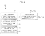
- the main controller (60) is arranged in the outdoor unit (11). As shown in FIG. 2 , the main controller (60) includes a target low pressure determining section (61), a target high pressure determining section (62), a compressor control section (63), an outdoor expansion valve control section (64), and a target superheat degree changing section (65).
- the main controller (60) receives measurements of the high pressure sensor (51), the low pressure sensor (52), the suction temperature sensor (53), the outdoor gas temperature sensor (54), the room air temperature sensors (55a, 55b), and the outdoor air temperature sensor (58).
- the sub-controllers (70a, 70b) are arranged in the indoor units (12, 13), respectively. As shown in FIG. 2 , the sub-controllers (70a, 70b) include indoor expansion valve control sections (71 a, 71b), respectively. Each of the sub-controllers (70a, 70b) receives a measurement of the low pressure sensor (52). Each of the sub-controllers (70a, 70b) receives measurements of the indoor gas temperature sensor (56, 56b) and the indoor liquid temperature sensor (57, 57b) arranged in the same indoor unit (12, 13).
- the main controller (60) and the sub-controllers (70a, 70b) control the operation of the air conditioner (10) using the measurements input from the sensors. Details of the control operation performed by the main controller (60) and the sub-controllers (70a, 70b) will be described in detail below.
- the air conditioner (10) of the present embodiment selectively performs air cooling operation as cooling operation, and air heating operation as heating operation. Switching between the air cooling operation and the air heating operation is performed by switching the four-way switching valve (32).
- the four-way switching valve (32) is set to the first state (the state indicated by a solid line in FIG. 1 ).
- the outdoor expansion valve (34) is fully opened, and the degrees of opening of the indoor expansion valves (42, 47) are suitably adjusted.
- the refrigerant circuit (20) performs a refrigeration cycle by circulating the refrigerant.
- the outdoor heat exchanger (33) functions as a gas cooler
- each of the indoor heat exchangers (41, 46) functions as an evaporator.
- the supercritical refrigerant discharged from the compressor (31) passes through the four-way switching valve (32) to enter the outdoor heat exchanger (33), and dissipates heat to the outdoor air.
- the refrigerant flowing out of the outdoor heat exchanger (33) passes through the outdoor expansion valve (34) and the receiver (35), flows into the liquid flow pipe (21), and is distributed to the indoor circuits (40, 45).
- Each of the refrigerant streams that entered the corresponding indoor circuit (40, 45) is reduced in pressure as it passes through the indoor expansion valve (42, 47) to reach a gas-liquid two phase state, and absorbs heat from the room air in the indoor heat exchanger (41, 46) to evaporate.
- Each of the indoor units (12, 13) feeds the room air cooled in the indoor heat exchanger (41, 46) to the inside of a room.
- the refrigerant streams that passed through the indoor heat exchangers (41, 46), respectively, flow into the gas flow pipe (22) to merge with each other, and the merged stream is sucked into the compressor (31) after passing through the four-way switching valve (32).
- the compressor (31) compresses the sucked refrigerant, and discharges the compressed refrigerant.
- the four-way switching valve (32) is set to the second state (the state indicated by a broken line in FIG. 1 ).
- the degrees of opening of the outdoor expansion valve (34) and the indoor expansion valves (42, 47) are suitably adjusted.
- the refrigerant circuit (20) performs a refrigeration cycle by circulating the refrigerant.
- each of the indoor heat exchangers (41, 46) functions as a gas cooler
- the outdoor heat exchanger (33) functions as an evaporator.
- the supercritical refrigerant discharged from the compressor (31) passes through the four-way switching valve (32) to enter the gas flow pipe (22), and is distributed to the indoor circuits (40, 45).
- Each of the refrigerant streams that entered the corresponding indoor circuit (40, 45) dissipates heat to the room air in the indoor heat exchanger (41, 46).
- Each of the indoor units (12, 13) feeds the room air heated in the indoor heat exchanger (41, 46) to the inside of the room.
- the refrigerant flowing out of the indoor heat exchanger (41, 46) flows into the liquid flow pipe (21) after passing through the indoor expansion valve (42, 47), and then flows into the outdoor circuit (3 0).
- the refrigerant that entered the outdoor circuit (30) is sent to the outdoor expansion valve (34) after passing through the receiver (35), and is reduced in pressure as it passes through the outdoor expansion valve (34) to reach a gas-liquid two phase state.
- the refrigerant that passed through the outdoor expansion valve (34) is sent to the outdoor heat exchanger (33), and absorbs heat from the outdoor air to evaporate.
- the refrigerant flowing out of the outdoor heat exchanger (33) passes through the four-way switching valve (32), and is sucked into the compressor (31).
- the compressor (31) compresses the sucked refrigerant, and discharges the compressed refrigerant.
- the main controller (60) and the sub-controllers (70a, 70b) control the operation of the air conditioner (10) based on the measurements input from the sensors.
- the main controller (60) and the sub-controllers (70a, 70b) in the air cooling operation will be described.
- the target low pressure determining section (61), the compressor control section (63), and the target superheat degree changing section (65) of the main controller (60) are operated.
- the outdoor expansion valve control section (64) performs only operation of keeping the outdoor expansion valve (34) fully opened, and the target high pressure determining section (62) is suspended.
- the indoor expansion valve control section (71 a, 71 b) is operated.
- the indoor expansion valve control section (71a, 71b) of each of the sub-controllers (70a, 70b) adjusts the degree of opening of the indoor expansion valve (42, 47) arranged in the corresponding indoor unit (12, 13). Specifically, in a first indoor unit (12), the indoor expansion valve control section (71 a) of the sub-controller (70a) adjusts the degree of opening of a first expansion valve (42) in such a manner that the degree of superheat of the refrigerant at the exit of a first indoor heat exchanger (41) reaches the predetermined target degree of superheat.
- the indoor expansion valve control section (71b) of the sub-controller (70b) adjusts the degree of opening of a second indoor expansion valve (47) in such a manner that the degree of superheat of the refrigerant at the exit of a second indoor heat exchanger (46) reaches the predetermined target degree of superheat.
- the indoor expansion valve control section (71a, 71 b) calculates the degree of superheat of the refrigerant at the exit of the indoor heat exchanger (41, 46) in the corresponding indoor unit (12, 13) by subtracting saturation temperature of the refrigerant associated with a detected value of the low pressure sensor (52) from a detected value of the indoor gas temperature sensor (56, 56b) in the corresponding indoor unit (12, 13). Then, the degree of opening of the indoor expansion valve (42, 47) in the corresponding indoor unit (12, 13) is adjusted in such a manner that the calculated degree of superheat reaches the target degree of superheat.
- the control of the degree of opening of the indoor expansion valve (42, 47) by the indoor expansion valve control section (71a, 71b) is performed by general feedback control, such as PID control etc.
- the indoor expansion valve control section (71a, 71b) reduces the degree of opening of the indoor expansion valve (42, 47) to reduce the flow rate of the refrigerant passing through the indoor heat exchanger (41, 46), thereby increasing the degree of superheat of the refrigerant at the exit of the indoor heat exchanger (41, 46).
- the indoor expansion valve control section (71 a, 71 b) increases the degree of opening of the indoor expansion valve (42, 47) to increase the flow rate of the refrigerant passing through the indoor heat exchanger (41, 46), thereby reducing the degree of superheat of the refrigerant at the exit of the indoor heat exchanger (41, 46).
- the target degree of superheat is set at a certain standard value (e.g., 5°C) except for the case where the target degree of superheat is changed by the target superheat degree changing section (65).
- the target low pressure determining section (61) is configured to perform target low pressure determining operation.
- the target low pressure which is a target value of the low pressure of the refrigeration cycle, is determined to correspond to a cooling load of the indoor unit (12, 13) in the air cooling operation.
- the target low pressure determining section (61) determines whether air cooling capability of the indoor unit (12, 13) is sufficient or not based on the measurements of the room air temperature sensors (55a, 55b), set room temperature for cooling the room, etc. Then, when the target low pressure determining section (61) has made a determination that the air cooling capability of the indoor unit (12, 13) is insufficient, the target low pressure is reduced to increase the air cooling capability. When the target low pressure determining section (61) has made a determination that the air cooling capability of the indoor unit (12, 13) is excessive, the target low pressure is increased to reduce the air cooling capability.
- the compressor control section (63) is configured to perform capacity control operation.
- operational capacity of the compressor (31) is adjusted in such a manner that the measurement of the low pressure sensor (52) (i.e., an actual measurement of the low pressure of the refrigeration cycle) reaches the target low pressure.
- the compressor control section (63) adjusts the operational capacity of the compressor (31) using the low pressure of the refrigeration cycle as a control parameter in such a manner that the control parameter reaches the target low pressure.
- the compressor control section (63) changes a frequency of alternating current fed to a motor of the compressor (31) to change rotation speed of the compression mechanism driven by the motor, thereby changing the operational capacity of the compressor (31).
- the compressor control section (63) increases the rotation speed of the motor of the compressor (31) to increase the operational capacity of the compressor (31), thereby reducing the low pressure of the refrigeration cycle.
- the compressor control section (63) reduces the rotation speed of the motor of the compressor (31) to reduce the operational capacity of the compressor (31), thereby increasing the low pressure of the refrigeration cycle.
- the compressor control section (63) calculates a command value for changing a frequency of the alternating current fed to the motor of the compressor (31) using the measurement of the low pressure sensor (52) and the predetermined control gain. Specifically, in the compressor control section (63), the command value for changing the frequency of the alternating current is increased as a difference between the measurement of the low pressure sensor (52) and the target low pressure is increased. Further, the command value for changing the frequency of the alternating current is reduced as the difference between the measurement of the low pressure sensor (52) and the target low pressure is reduced.
- the compressor control section (63) determines that the air cooling capability is excessive relative to the cooling load, and stops the compressor (31). Further, when a difference between the measurement of the room air temperature sensor (55a, 55b) and the set room temperature for cooling the room reaches or exceeds a certain level, the compressor control section (63) determines that the air inside the room has to be cooled, and starts the compressor (31).
- the target superheat degree changing section (65) is configured to perform target superheat degree changing operation.
- the target superheat degree changing section (65) counts the number of times the compressor (31) is stopped by the compressor control section (63).
- the predetermined number e.g., two
- a predetermined period of time e.g., in 15 minutes
- the target superheat degree changing section (65) forcibly increases the target degree of superheat from a standard value (e.g., 5°C).
- the indoor expansion valve control section (71a, 71b) adjusts the degree of opening of the indoor expansion valve (42, 47) using the target degree of superheat increased from the standard value.
- the target superheat degree changing section (65) sets an upper limit value on the increase in target degree of superheat by the target superheat degree changing operation to prevent the temperature of the refrigerant discharged from the compressor (31) from being too high.
- the target high pressure determining section (62), the compressor control section (63), the outdoor expansion valve control section (64), and the target superheat degree changing section (65) of the main controller (60) are operated, and the target low pressure determining section (61) is suspended.
- the indoor expansion valve control section (71a, 71 b) is operated.
- the indoor expansion valve control section (71a, 71b) of each of the sub-controllers (70a, 70b) adjusts the degree of opening of the indoor expansion valve (42, 47) in the corresponding indoor unit (12, 13). This operation is the same as that in the air cooling operation. However, in the air heating operation, the indoor expansion valve control section (71a, 71b) adjusts the degree of opening of the indoor expansion valve (42, 47) in such a manner that a detected value of the indoor liquid temperature sensor (57, 57b) in the corresponding indoor unit (12, 13) reaches the predetermined target value.
- the indoor expansion valve control section (71a, 71b) adjusts the degree of opening of the indoor expansion valve (42, 47) in such a manner that the temperature of the refrigerant at the exit of the indoor heat exchanger (41, 46) which functions as a gas cooler reaches the predetermined target value.
- the control of the degree of opening of the indoor expansion valve (42, 47) by the indoor expansion valve control section (71 a, 71b) is performed by general feedback control, such as PID control etc.
- the indoor expansion valve control section (71 a, 71b) reduces the degree of opening of the indoor expansion valve (42, 47) to reduce the flow rate of the refrigerant passing through the indoor heat exchanger (41, 46), thereby reducing the temperature of the refrigerant at the exit of the indoor heat exchanger (41, 46).
- the indoor expansion valve control section (71a, 71b) increases the degree of opening of the indoor expansion valve (42, 47) to increase the flow rate of the refrigerant passing through the indoor heat exchanger (41, 46), thereby increasing the temperature of the refrigerant at the exit of the indoor heat exchanger (41, 46).
- the target high pressure determining section (62) is configured to perform target high pressure determining operation.
- the target high pressure which is a target value of the high pressure of the refrigeration cycle, is determined to correspond to a heating load of the indoor unit (12, 13) in the air heating operation.
- the target high pressure determining section (62) determines whether the air heating capability of the indoor unit (12, 13) is sufficient or not based on the measurements of the room air temperature sensors (55a, 55b), the set room temperature for heating the room, etc.
- the target high pressure determining section (62) has made a determination that the air heating capability of the indoor unit (12, 13) is insufficient, the target high pressure is increased to increase the air heating capability.
- the target high pressure determining section (62) has made a determination that the air heating capability of the indoor unit (12, 13) is excessive, the target high pressure is reduced to reduce the air heating capability.
- the compressor control section (63) is configured to perform capacity control operation.
- operational capacity of the compressor (31) is adjusted in such a manner that the measurement of the high pressure sensor (51) (i.e., an actual measurement of the high pressure of the refrigeration cycle) reaches the target high pressure.
- the compressor control section (63) adjusts the operational capacity of the compressor (31) using the high pressure of the refrigeration cycle as a control parameter in such a manner that the control parameter reaches the target high pressure.
- the compressor control section (63) changes a frequency of alternating current fed to a motor of the compressor (31) to change rotation speed of the compression mechanism driven by the motor, thereby changing the operational capacity of the compressor (31).
- the compressor control section (63) increases the rotation speed of the motor of the compressor (31) to increase the operational capacity of the compressor (31), thereby increasing the high pressure of the refrigeration cycle.
- the compressor control section (63) reduces the rotation speed of the motor of the compressor (31) to reduce the operational capacity of the compressor (31), thereby reducing the high pressure of the refrigeration cycle.
- the compressor control section (63) calculates a command value for changing a frequency of the alternating current fed to the motor of the compressor (31) using the measurement of the high pressure sensor (51) and the predetermined control gain. Specifically, in the compressor control section (63), the command value for changing the frequency of the alternating current is increased as a difference between the measurement of the high pressure sensor (51) and the target high pressure is increased. Further, the command value for changing the frequency of the alternating current is reduced as the difference between the measurement of the high pressure sensor (51) and the target high pressure is reduced.
- the outdoor expansion valve control section (64) is configured to perform flow rate control operation.
- the degree of opening of the outdoor expansion valve (34) is adjusted in such a manner that the degree of superheat of the refrigerant at the exit of the outdoor heat exchanger (33) which functions as the evaporator in the air heating operation reaches the target degree of superheat.
- the outdoor expansion valve control section (64) adjusts the degree of opening of the outdoor expansion valve (34) to control the flow rate of the refrigerant passing through the outdoor expansion valve (34).
- the control of the degree of opening of the outdoor expansion valve (34) by the outdoor expansion valve control section (64) is performed by general feedback control, such as PID control etc.
- the outdoor expansion valve control section (64) calculates the degree of superheat of the refrigerant at the exit of the outdoor heat exchanger (33) by subtracting saturation temperature of the refrigerant associated with a detected value of the low pressure sensor (52) from a detected value of the outdoor gas temperature sensor (54). Then, the degree of opening of the outdoor expansion valve (34) is adjusted in such a manner that the calculated degree of superheat reaches the target degree of superheat.
- the outdoor expansion valve control section (64) reduces the degree of opening of the outdoor expansion valve (34) to reduce the flow rate of the refrigerant passing through the outdoor heat exchanger (33), thereby increasing the degree of superheat of the refrigerant at the exit of the outdoor heat exchanger (33).
- the outdoor expansion valve control section (64) increases the degree of opening of the outdoor expansion valve (34) to increase the flow rate of the refrigerant passing through the outdoor heat exchanger (33), thereby reducing the degree of superheat of the refrigerant at the exit of the outdoor heat exchanger (33).
- the target superheat degree changing section (65) is configured to perform target superheat degree changing operation. Specifically, like in the air cooling operation, the target superheat degree changing section (65) forcibly increases the target degree of superheat from a standard value (e.g., 5°C) when the number of times the compressor is stopped by the compressor control section (63) reaches the predetermined number within a predetermined period of time. After the target superheat degree changing section (65) forcibly increased the target degree of superheat, the outdoor expansion valve control section (64) adjusts the degree of opening of the outdoor expansion valve (34) using the target degree of superheat increased from the standard value.
- a standard value e.g., 5°C
- the target superheat degree changing section (65) sets an upper limit value on the increase in target degree of superheat by the target superheat degree changing operation to prevent the temperature of the refrigerant discharged from the compressor (31) from being too high.
- the target superheat degree changing section (65) of the main controller (60) forcibly increases the target degree of superheat from the standard value when the capability of the air conditioner (10) is excessive, and a frequency at which the compressor (31) is stopped by the compressor control section (63) is increased.
- the indoor expansion valve control section (71 a, 71b) of the sub-controller (70a, 70b) adjusts the degree of opening of the indoor expansion valve (42, 47) in such a manner that the degree of superheat of the refrigerant flowing from the indoor heat exchanger (41, 46) to the compressor (31) reaches the increased target degree of superheat.
- the outdoor expansion valve control section (64) of the main controller (60) adjusts the degree of opening of the outdoor expansion valve (34) in such a manner that the degree of superheat of the refrigerant flowing from the outdoor heat exchanger (33) to the compressor (31) reaches the increased target degree of superheat.
- the degree of superheat of the refrigerant at the exit of the evaporator is increased as the flow rate of the refrigerant passing through the evaporator is reduced.
- the degrees of opening of the indoor expansion valves (42, 47) and the outdoor expansion valve (34) are reduced as the target degree of superheat is increased.
- the indoor expansion valves (42, 47) and the outdoor expansion valve (34) are brought into the state where the flow rate of the refrigerant passing through them is reduced (i.e., the state where the degrees of opening are set low).
- the rotation speed of the compression mechanism of the compressor (31) kept constant, the amount of the refrigerant circulating in the refrigerant circuit (20) is reduced as the target degree of superheat is increased, thereby reducing the capability of the air conditioner (10).
- the lower limit value of the capability of the air conditioner (10) is reduced as the target degree of superheat is increased. Therefore, the compressor (31), which would have to be stopped by the compressor control section (63) before the target degree of superheat is increased, is more likely to be continuously operated after the target degree of superheat is increased.
- the possibility that the compressor (31) is stopped due to the excessive capability of the air conditioner (10) relative to the load can be reduced.
- the air conditioner (10) which performs the supercritical cycle in which "high energy is consumed until the high pressure and the low pressure of the refrigeration cycle reach the appropriate values after the compressor (31) is started” the number of times the compressor (31) is started and stopped for capability adjustment can be reduced. Therefore, according to the present embodiment, the number of times the compressor (31) is started and stopped for capability adjustment is reduced, thereby reducing the power consumed while the air conditioner (10) is operated, and improving operation efficiency of the air conditioner (10).
- a second embodiment of the invention will be described. This embodiment is the same as the first embodiment except that the structure of the main controller (60) of the air conditioner (10) is changed.
- the main controller (60) of the present embodiment includes a target control value changing section (66) in place of the target superheat degree changing section (65) described in the first embodiment.
- the target low pressure determining section (61), the target high pressure determining section (62), the compressor control section (63), and the outdoor expansion valve control section (64) are operated in the same manner as described in the first embodiment.
- the target control value changing section (66) is configured to perform target control value changing operation.
- the target control value changing section (66) counts the number of times the compressor (31) is stopped by the compressor control section (63).
- the predetermined number e.g., two
- a predetermined period of time e.g. 15 minutes
- the target control value changing section (66) performs operation of forcibly changing the target low pressure as the target control value changing operation. Specifically, when the number of times the compressor is stopped by the compressor control section (63) reaches the predetermined number within the predetermined period of time, the target control value changing section (66) increases the target low pressure used in the compressor control section (63) from a standard target value which is determined by the target low pressure determining section (61). Then, at a point of time when the compressor (31) is started, the compressor control section (63) adjusts operational capacity of the compressor (31) using the target low pressure increased by the target control value changing section (66).
- the compressor control section (63) gradually reduces the target low pressure in such a manner that the target low pressure reaches the standard target value at a point of time when the predetermined period of time (e.g., 4 minutes) has passed from the start of the compressor (31).
- the predetermined period of time e.g., 4 minutes
- the target low pressure is set higher than the standard target value for some time after the start of the compressor (31).
- a difference between the measurement of the low pressure sensor (52) and the target low pressure is smaller than a difference between the measurement and the target low pressure which is not changed from the standard target value.
- the compressor (31) which would have to be stopped by the compressor control section (63) when the target low pressure is not changed from the standard target value, is more likely to be continuously operated.
- the target control value changing section (66) performs operation of forcibly changing the target high pressure as the target control value changing operation. Specifically, when the number of times the compressor is stopped by the compressor control section (63) reaches the predetermined number in the predetermined period of time, the target control value changing section (66) reduces the target high pressure used in the compressor control section (63) from a standard target value determined by the target high pressure determining section (62). Then, at a point of time when the compressor (31) is started, the compressor control section (63) adjusts the operational capacity of the compressor (31) using the target high pressure reduced by the target control value changing section (66).
- the compressor control section (63) gradually increases the target high pressure in such a manner that the target high pressure reaches the standard target value at a point of time when a predetermined period of time (e.g., 4 minutes) has passed from the start of the compressor (31).
- a predetermined period of time e.g., 4 minutes
- the target high pressure is set lower than the standard target value for some period of time after the start of the compressor (31).
- a difference between the measurement of the high pressure sensor (51) and the target high pressure is smaller than a difference between the measurement and the target high pressure which is not changed from the standard target value.
- the compressor (31) which would have to be stopped by the compressor control section (63) when the target high pressure is not changed from the standard target value, is more likely to be continuously operated.
- the possibility that the compressor (31) is stopped due to the excessive capability of the air conditioner (10) relative to the load can be reduced.
- the number of times the compressor (31) is started and stopped for capability adjustment is reduced, thereby reducing power consumed while the air conditioner (10) is operated, and improving the operation efficiency of the air conditioner (10).
- the compressor control section (63) of the present embodiment may be configured to use, as a control parameter in the air cooling operation, evaporating temperature of the refrigerant in the indoor heat exchanger (41, 46) which functions as an evaporator.
- the target low pressure determining section (61) is replaced with a target evaporating temperature determining section.
- the target evaporating temperature determining section determines target evaporating temperature of the refrigerant in the indoor heat exchanger (41, 46) based on the cooling load of the air conditioner (10).
- the target control value changing section (66) of this alternative example increases the target evaporating temperature used in the compressor control section (63) from a standard target value determined by the target evaporating temperature determining section, and gradually reduces the target evaporating temperature in such a manner that the target evaporating temperature reaches the standard target value at a point of time when a predetermined period of time has passed after the start of the compressor (31).
- a third embodiment of the invention will be described.
- the present embodiment is the same as the first embodiment except that the structure of the main controller (60) of the air conditioner (10) is changed.
- the main controller (60) of the present embodiment includes a gain adjustment section (67) in place of the target superheat degree changing section (65) of the first embodiment.
- the target low pressure determining section (61), the target high pressure determining section (62), the compressor control section (63), and the outdoor expansion valve control section (64) are operated in the same manner as described in first embodiment.
- the gain adjustment section (67) is configured to perform gain adjustment operation. In the gain adjustment operation, the gain adjustment section (67) adjusts a control gain used in the compressor control section (63) in accordance with a difference between the measurement of the outdoor air temperature sensor (58) (i.e., an actual measurement of outside temperature) and the set room temperature.
- the gain adjustment section (67) compares the measurement of the outdoor air temperature sensor (58) and the set room temperature. In the air cooling operation, the cooling load for cooling the room is reduced as a value obtained by subtracting the set room temperature from the measurement of the outdoor air temperature sensor (58) is reduced. Therefore, the gain adjustment section (67) sets the control gain used in the compressor control section (63) smaller as the value obtained by subtracting the set room temperature from the measurement of the outdoor air temperature sensor (58) is smaller.
- the compressor control section (63) of the present embodiment adjusts the capacity of the compressor (31) using the small control gain set by the gain adjustment section (67). Specifically, the compressor control section (63) calculates a command value for changing a frequency of alternating current fed to the motor of the compressor (31) using a difference between the measurement of the low pressure sensor (52) and the target low pressure, and the control gain. With the difference between the measurement of the low pressure sensor (52) and the target low pressure kept constant, the command value for changing the frequency of the alternating current is reduced as the control gain is reduced in the compressor control section (63).
- the gain adjustment section (67) compares the measurement of the outdoor air temperature sensor (58) and the set room temperature. In the air heating operation, the heating load for heating the room is reduced as the value obtained by subtracting the measurement of the outdoor air temperature sensor (58) from the set room temperature is reduced. Thus, the gain adjustment section (67) sets the control gain used in the compressor control section (63) smaller as the value obtained by subtracting the measurement of the outdoor air temperature sensor (58) from the set room temperature is smaller.
- the compressor control section (63) of the present embodiment adjusts the capacity of the compressor (31) using the small control gain set by the gain adjustment section (67). Specifically, the compressor control section (63) calculates a command value for changing a frequency of alternating current fed to the motor of the compressor (31) using a difference between the measurement of the high pressure sensor (51) and the target high pressure, and the control gain. With the difference between the measurement of the high pressure sensor (51) and the target high pressure kept constant, the command value for changing the frequency of the alternating current is reduced as the control gain is reduced in the compressor control section (63).
- the gain adjustment section (67) of the present embodiment reduces the control gain as the load of the air conditioner (10) is reduced.
- the command value calculated based on the measurement of the low pressure sensor (52) or the high pressure sensor (51), and the control gain is reduced as compared with the case where the control gain is constant. Therefore, with the control gain reduced by the gain adjustment section (67) according to the present embodiment, the compressor (31), which would have to be stopped by the compressor control section (63) when the control gain is constant, is more likely to be continuously operated.
- the compressor (31) is less likely to be stopped due to the excessive capability of the air conditioner (10) relative to the load.
- the number of times the compressor (31) is started and stopped for capability adjustment is reduced, thereby reducing power consumed while the air conditioner (10) is operated, and improving the operation efficiency of the air conditioner (10).
- the present invention is useful for a refrigeration apparatus which performs a refrigeration cycle in which high pressure is set higher than critical pressure of the refrigerant.
Landscapes
- Engineering & Computer Science (AREA)
- Physics & Mathematics (AREA)
- Mechanical Engineering (AREA)
- Thermal Sciences (AREA)
- General Engineering & Computer Science (AREA)
- Air Conditioning Control Device (AREA)
Abstract
An air conditioner (10) comprised of a refrigeration apparatus includes a main controller (60), and a sub-controller (70a, 70b). A compressor control section of the main controller (60) adjusts operational capacity of the compressor (31), and stops the compressor (31) when capability of the air conditioner (10) is excessive relative to a load. When a frequency at which the compressor (31) is started and stopped by the compressor control section is increased, a target superheat degree changing section of the main controller (60) forcibly increases a target degree of superheat. Then, in air cooling operation, the sub-controller (70a, 70b) adjusts the degree of opening of an indoor expansion valve (42, 47) based on the increased target degree of superheat. In air heating operation, the main controller (60) adjusts the degree of opening of an outdoor expansion valve (34) based on the increased target degree of superheat.
Description
- The present invention relates to refrigeration apparatuses which perform a refrigeration cycle in which high pressure is set higher than critical pressure of a refrigerant.
- Refrigeration apparatuses which perform a refrigeration cycle by circulating a refrigerant in a refrigerant circuit have been known. In a refrigeration apparatus disclosed by Patent Document 1, high pressure of the refrigeration cycle performed by the refrigerant circuit is set higher than critical pressure of the refrigerant. That is, the refrigerant circuit of the refrigeration apparatus performs a so-called supercritical cycle.
- In an air conditioner disclosed by Patent Document 2, a general refrigeration cycle is performed in which the high pressure is set lower than the critical pressure of the refrigerant. According to Patent Document 2, a target value for controlling the operation of the air conditioner is adjusted to reduce a frequency of starts and stops of a compressor in the air conditioner.
-
- Patent Document 1: Japanese Patent Publication No.
2001-116376 - Patent Document 2: Japanese Patent Publication No.
2002-061925 - In a refrigeration apparatus which performs the so-called supercritical cycle, the compressor may be started/stopped to adjust capability of the refrigeration apparatus. For example, even when a variable capacity compressor is used, and the capacity of the compressor is set to the lowest, the capability of the refrigeration apparatus may be too high relative to a load. In such a state, the compressor is stopped.
- In the supercritical cycle, the high pressure is higher than that in the general refrigeration cycle. Therefore, as compared with the general refrigeration cycle in which the high pressure is lower than the critical pressure of the refrigerant, the supercritical cycle consumes higher energy until the high pressure and the low pressure of the refrigeration cycle reach appropriate values after the compressor is started. Nevertheless, effective measures have not been taken so far to reduce the frequency of starts and stops of the compressor in the refrigeration apparatus which performs the supercritical cycle.
- In view of the foregoing, the present invention has been achieved. An object of the invention is to reduce the number of times the compressor is started and stopped in the refrigeration apparatus which performs the so-called supercritical cycle, thereby improving operation efficiency of the refrigeration apparatus.
- A first aspect of the invention is directed to a refrigeration apparatus including: a refrigerant circuit (20) which includes a compressor (31), an expansion mechanism (34, 42, 47), a heat source-side heat exchanger (33), and a utilization-side heat exchanger (41, 46) connected thereto, and performs a refrigeration cycle in which high pressure is set higher than critical pressure of a refrigerant; and a control means (80) which controls the compressor (31) and the expansion mechanism (34, 42, 47). The control means (80) is configured to perform capacity control operation of adjusting capacity of the compressor (31) in such a manner that a physical value representing an operating state of the refrigeration cycle performed by the refrigerant circuit (20) reaches a target control value, flow rate control operation of adjusting a flow rate of the refrigerant passing through the expansion mechanism (34, 42, 47) in such a manner that a degree of superheat of the refrigerant flowing from one of the heat source-side heat exchanger (33) and the utilization-side heat exchanger (41, 46) which functions as an evaporator to the compressor (31) reaches a target degree of superheat, and a target superheat degree changing operation of forcibly increasing the target degree of superheat when the compressor (13) is stopped by the capacity control operation.
- A second aspect of the invention is directed to a refrigeration apparatus including: a refrigerant circuit (20) which includes a compressor (31), an expansion mechanism (34, 42, 47), a heat source-side heat exchanger (33), and a utilization-side heat exchanger (41, 46) connected thereto, and performs a refrigeration cycle in which high pressure is set higher than critical pressure of a refrigerant; a control means (80) which controls the compressor (31), the refrigeration apparatus performing at least cooling operation in which the heat source-side heat exchanger (33) functions as a gas cooler, and the utilization-side heat exchanger (41, 46) functions as an evaporator. The control means (80) is configured to perform capacity control operation of adjusting capacity of the compressor (31) in such a manner that a control parameter, which is evaporating temperature of the refrigerant in the utilization-side heat exchanger (41, 46), or low pressure of the refrigeration cycle performed by the refrigerant circuit (20), reaches a target control value, and target control value changing operation of gradually reducing the target control value after the compressor (31) is started in such a manner that the target control value reaches a predetermined standard target value after a predetermined period of time from the start of the compressor (31).
- A third aspect of the invention is directed to a refrigeration apparatus including: a refrigerant circuit (20) which includes a compressor (31), an expansion mechanism (34, 42, 47), a heat source-side heat exchanger (33), and a utilization-side heat exchanger (41, 46) connected thereto, and performs a refrigeration cycle in which high pressure is set higher than critical pressure of a refrigerant; and a control means (80) which controls the compressor (31), the refrigeration apparatus performing at least heating operation in which the utilization-side heat exchanger (41, 46) functions as a gas cooler, and the heat source-side heat exchanger (33) functions as an evaporator. The control means (80) is configured to perform capacity control operation of adjusting capacity of the compressor (31) in such a manner that a control parameter, which is high pressure of the refrigeration cycle performed by the refrigerant circuit (20), reaches a target control value, and target control value changing operation of gradually increasing the target control value after the compressor (31) is started in such a manner that the target control value reaches a predetermined standard target value after a predetermined period of time from the start of the compressor (31).
- A fourth aspect of the invention is directed to a refrigeration apparatus including: a refrigerant circuit (20) which includes a compressor (31), an expansion mechanism (34, 42, 47), a heat source-side heat exchanger (33), and a utilization-side heat exchanger (41, 46) connected thereto, and performs a refrigeration cycle in which high pressure is set higher than critical pressure of a refrigerant; and a control means (80) which controls the compressor (31). The control means (80) is configured to perform capacity control operation of adjusting capacity of the compressor (31) based on a command value calculated using a physical value representing an operating state of the refrigeration cycle performed by the refrigerant circuit (20), and a control gain in such a manner that the physical value reaches a target control value, and gain adjustment operation of reducing the control gain as a load of the refrigeration apparatus is reduced.
- According to the first to fourth aspects of the invention, the refrigeration cycle is performed by circulating the refrigerant in the refrigerant circuit (20). In this case, the pressure of the refrigerant discharged from the compressor (31) is higher than the critical pressure of the refrigerant. In the refrigerant circuit (20), one of the heat source-side heat exchanger (33) and the utilization-side heat exchanger (41, 46) functions as a gas cooler, and the other functions as an evaporator.
- According to the first aspect of the invention, the control means (80) performs the capacity control operation. In the capacity control operation, capacity of the compressor (31) is adjusted in such a manner that a predetermined physical value reaches a target control value. The control means (80) stops the compressor (31) when the capacity of the compressor (31) cannot be reduced anymore although the predetermined physical value is deviated from the target control value. When the compressor (31) is stopped by the capacity control operation, the control means (80) performs the target superheat degree changing operation to forcibly increase the target degree of superheat. Then, after the compressor (31) is restarted, the control means (80) performs the flow rate control operation using the target degree of superheat increased by the target superheat degree changing operation. Specifically, the control means (80) adjusts the flow rate of the refrigerant passing through the expansion mechanism (34, 42, 47) in such a manner that the degree of superheat of the refrigerant flowing from the heat exchanger (33, 41, 46) which functions as an evaporator to the compressor (31) reaches the increased target degree of superheat.
- According to the first aspect of the invention, the expansion mechanism (34, 42, 47) is brought into the state where the flow rate of the refrigerant passing through the expansion mechanism is reduced as the target degree of superheat is increased. With the capacity of the compressor (31) kept constant, the amount of the refrigerant circulating in the refrigerant circuit (20) is reduced as the target degree of superheat is increased, thereby reducing the capability of the refrigeration apparatus (10). That is, a lower limit value of the capability of the refrigeration apparatus (10) is reduced as the target degree of superheat is increased. Thus, the compressor (31), which would have to be stopped by the control means (80) before the target degree of superheat is increased, is more likely to be continuously operated after the target degree of superheat is increased.
- According to the second aspect of the invention, the control means (80) performs the capacity control operation, and the target control value changing operation in the cooling operation. In the capacity control operation, the control means (80) adjusts the capacity of the compressor (31) in such a manner that a control parameter, which is evaporating temperature of the refrigerant in the utilization-side heat exchanger (41, 46), or the low pressure of the refrigeration cycle performed by the refrigerant circuit (20), reaches a target control value. The control means (80) stops the compressor (31) when the capacity of the compressor (31) cannot be reduced anymore although the control parameter is deviated from the target control value. Then, after the compressor (31) is restarted, the control means (80) performs the target control value changing operation. In the target control value changing operation, the control means (80) sets the target control value at a point of time when the compressor (31) is restarted higher than a standard target value, and then gradually reduces the target control value to be close to the standard target value in a predetermined period of time from the point of time. During this period, in the capacity control operation, the capacity of the compressor (31) is adjusted using the target control value adjusted by the target control value changing operation.
- Immediately after the start of the compressor (31), there is a big difference between the control parameter, which is the evaporating temperature of the refrigerant, or an actual measurement of the low pressure of the refrigeration cycle, and the standard target value. Thus, when the target control value is not changed from the standard target value immediately after the start of the compressor (31), the capacity of the compressor (31) is abruptly increased to bring the control parameter close to the standard target value as soon as possible. When the cooling capability of the refrigeration apparatus (10) is abruptly increased due to the abrupt increase in capacity of the compressor (31), the cooling capability becomes excessive in a relatively short time after the start of the compressor (31), and the compressor (31) has to be stopped again.
- In contrast, according to the control means (80) of the second aspect of the invention, the target control value is set higher than the standard target value for some time after the start of the compressor (31). Thus, even immediately after the start of the compressor (31), the difference between the control parameter, which is the evaporating temperature of the refrigerant or the actual measurement of the low pressure of the refrigeration cycle, and the target control value is smaller than the difference in the case where the target control value is not changed from the standard target value. This alleviates the abrupt increase in capacity of the compressor (31) after the start of the compressor (31), thereby gently changing the cooling capability of the refrigeration apparatus (10). Thus, with the target control value set higher than the standard target value by the control means (80) of the present invention, the compressor (31), which would have to be stopped by the control means (80) when the target control value is not changed from the standard target value, is more likely to be continuously operated.
- According to the third aspect of the invention, the control means (80) performs the capacity control operation, and the target control value changing operation in the heating operation. In the capacity control operation, the control means (80) adjusts the capacity of the compressor (31) in such a manner that the control parameter, which is the high pressure of the refrigeration cycle performed by the refrigerant circuit (20), reaches the target control value. The control means (80) stops the compressor (31) when the capacity of the compressor (31) cannot be reduced anymore although the control parameter is deviated from the target control value. Then, after the compressor (31) is restarted, the control means (80) performs the target control value changing operation. In the target control value changing operation, the control means (80) sets the target control value at a point of time when the compressor (31) is restarted lower than the standard target value, and then gradually increases the target control value to be close to the standard target value in a predetermined period of time from the point of time. During this period, in the capacity control operation, the capacity of the compressor (31) is adjusted using the target control value adjusted by the target control value changing operation.
- Immediately after the start of the compressor (31), there is a big difference between the control parameter, which is the actual measurement of the high pressure of the refrigeration cycle, and the standard target value. Thus, when the target control value is not changed from the standard target value immediately after the start of the compressor (31), the capacity of the compressor (31) is abruptly increased to bring the control parameter close to the standard target value as soon as possible. When the heating capability of the refrigeration apparatus (10) is abruptly increased due to the abrupt increase in capacity of the compressor (31), the heating capability becomes excessive in a relatively short time after the start of the compressor (31), and the compressor (31) has to be stopped again.
- In contrast, according to the control means (80) of the third aspect of the invention, the target control value is set lower than the standard target value for some time after the start of the compressor (31). Thus, even immediately after the start of the compressor (31), the difference between the actual measurement of the high pressure of the refrigeration cycle as the control parameter, and the target control value is smaller than the difference in the case where the target control value is not changed from the standard target value. This alleviates the abrupt increase in capacity of the compressor (31) after the start of the compressor (31), thereby gently changing the heating capability of the refrigeration apparatus (10). Thus, with the target control value set lower than the standard target value by the control means (80) of the present invention, the compressor (31), which would have to be stopped by the control means (80) when the target control value is not changed from the standard target value, is more likely to be continuously operated.
- According to the fourth aspect of the invention, the control means (80) performs the capacity control operation, and the target control value changing operation. In the capacity control operation, the capacity of the compressor (31) is adjusted in such a manner that a predetermined physical value reaches a target control value. The control means (80) stops the compressor (31) when the capacity of the compressor (31) cannot be reduced anymore although the predetermined physical value is deviated from the target control value. Further, the control means (80) performs the gain adjustment operation of reducing the control gain used in the capacity control operation as the load of the refrigeration apparatus (10) is reduced.
- When the control gain is kept high although the load of the refrigeration apparatus (10) is reduced, the amount of change in capacity of the compressor (31) determined based on a deviation between the predetermined physical value and the target control value is increased. As a result, the capability of the refrigeration apparatus (10) becomes excessive relative to the load, and the compressor (31) is more likely to be stopped.
- In contrast, according to the control means (80) of the fourth aspect of the invention, the control gain is reduced as the load of the refrigeration apparatus (10) is reduced. Thus, the command value calculated using the predetermined physical value and the control gain is reduced as compared with the case where the control gain is constant. With the control gain reduced by the control means (80) according to the invention, the compressor (31), which would have to be stopped by the control means (80) when the control gain is constant, is more likely to be continuously operated.
- As described above, according to the first aspect of the invention, the target degree of superheat is increased to reduce the lower limit value of the capability of the refrigeration apparatus (10), thereby reducing the possibility that the compressor (31) is stopped due to excessive capability of the refrigeration apparatus (10) relative to the load. According to the second aspect of the invention, the control parameter in the cooling operation is set higher immediately after the start of the compressor (31), thereby reducing the possibility that the compressor (31) is stopped due to excessive cooling capability of the refrigeration apparatus (10) relative to the load. According to the third aspect of the invention, the control parameter in the heating operation is set lower immediately after the start of the compressor (31), thereby reducing the possibility that the compressor (31) is stopped due to excessive heating capability of the refrigeration apparatus (10) relative to the load. According to the fourth aspect of the invention, the control gain is set lower when the load of the refrigeration apparatus (10) is small, thereby reducing the possibility that the compressor (31) is stopped due to excessive capability of the refrigeration apparatus (10) relative to the load.
- Thus, according to the invention, in the refrigeration apparatus (10) which performs the so-called supercritical cycle, the possibility that the compressor (31) is stopped due to the excessive capability of the refrigeration apparatus (10) relative to the load can be reduced. Specifically, in the refrigeration apparatus (10) which performs the supercritical cycle in which "high energy is consumed until the high pressure and the low pressure of the refrigeration cycle reach the appropriate values after the compressor (31) is started," the number of times the compressor (31) is started and stopped for capability adjustment can be reduced. Thus, according to the invention, the number of times the compressor (31) is started and stopped for capability adjustment can be reduced, thereby reducing the power consumed while the refrigeration apparatus (10) is operated, and improving operation efficiency of the refrigeration apparatus (10).
-
- [
FIG. 1] FIG. 1 is a refrigerant circuit diagram illustrating the schematic structure of an air conditioner of a first embodiment. - [
FIG. 2] FIG. 2 is a block diagram illustrating the structure of a main controller and sub-controllers of the first embodiment. - [
FIG. 3] FIG. 3 is a block diagram illustrating the structure of a main controller of a second embodiment. - [
FIG. 4] FIG. 4 is a block diagram illustrating the structure of a main controller of a third embodiment. -
- 10
- Air conditioner (refrigeration apparatus)
- 20
- Refrigeration circuit
- 31
- Compressor
- 33
- Outdoor heat exchanger (heat source-side heat exchanger)
- 34
- Outdoor expansion valve (expansion mechanism)
- 41
- Indoor heat exchanger (utilization-side heat exchanger)
- 42
- Indoor expansion valve (expansion mechanism)
- 46
- Indoor heat exchanger (utilization-side heat exchanger)
- 47
- Indoor expansion valve (expansion mechanism)
- 60
- Main controller
- 70a
- Sub-controller
- 70b
- Sub-controller
- 80
- Control means
- Embodiments of the present invention will be described in detail with reference to the drawings. The embodiments described below are directed to an air conditioner (10) comprised of a refrigeration apparatus.
- As shown in
FIG. 1 , the air conditioner (10) of the present embodiment includes a single outdoor unit (11), and two indoor units (12, 13). The outdoor unit (11) is placed outside. The indoor units (12, 13) are placed inside. The number of the outdoor unit (11) and the number of the indoor units (12, 13) are merely described as examples. The air conditioner (10) includes a main controller (60), and sub-controllers (70a, 70b). The main controller (60) and the sub-controllers (70a, 70b) constitute a control means (80). - In the air conditioner (10) of this embodiment, an outdoor circuit (30) of the outdoor unit (11) and indoor circuits (40, 45) of the indoor units (12, 13) are connected through a liquid flow pipe (21) and a gas flow pipe (22) to form a refrigerant circuit (20). The refrigerant circuit (20) is filled with carbon dioxide (CO2) as a refrigerant. The refrigerant circuit (20) performs a refrigeration cycle in which high pressure is set higher than critical pressure of carbon dioxide as the refrigerant.
- The outdoor unit (11) contains a single outdoor circuit (30). The outdoor circuit (30) includes the compressor (31), a four-way switching valve (32), an outdoor heat exchanger (33) as a heat source-side heat exchanger, an outdoor expansion valve (34) as an expansion mechanism, a receiver (35), a liquid stop valve (36), and a gas stop valve (37). The outdoor unit (11) is provided with an outdoor fan (16) for sending outdoor air to the outdoor heat exchanger (33).
- In the outdoor circuit (30), the compressor (31) is connected to a first port of the four-way switching valve (32) through a discharge side thereof, and is connected to a second port of the four-way switching valve (32) through a suction side thereof. The outdoor heat exchanger (33) is connected to a third port of the four-way switching valve through a gas end thereof, and is connected to an end of the outdoor expansion valve (34) through a liquid end thereof. The other end of the outdoor expansion valve (34) is connected to the liquid stop valve (36) through the receiver (35). A fourth port of the four-way switching valve (32) is connected to the gas stop valve (37).
- The indoor units (12, 13) contain indoor circuits (40, 45), respectively. Each of the indoor circuits (40, 45) includes an indoor heat exchanger (41, 46) as a utilization-side heat exchanger, and an indoor expansion valve (42, 47) as an expansion mechanism. The indoor heat exchanger (41, 46) and the indoor expansion valve (42, 47) in each of the indoor circuits (40, 45) are connected in series. Each of the indoor units (12, 13) contains an indoor fan (17, 18) for sending room air to the indoor heat exchanger (41, 46).
- In the refrigerant circuit (20), an end of the liquid flow pipe (21) is connected to the liquid stop valve (36). The other end of the liquid flow pipe (21) is branched in two, and the branched ends are connected to the ends of the indoor units (40, 45) near the indoor expansion valves (42, 47), respectively. An end of the gas flow pipe (22) is connected to the gas stop valve (37). The other end of the gas flow pipe (22) is branched in two, and the branched ends are connected to the ends of the indoor units (40, 45) near the indoor heat exchangers (41, 46), respectively. Specifically, the two indoor units (40, 45) are parallel-connected to the single outdoor circuit (30) in the refrigerant circuit (20).
- The compressor (31) is a hermetic compressor including a compression mechanism and a motor in a single casing. The outdoor heat exchanger (33), and the indoor heat exchangers (41, 46) are fin-and-tube air heat exchangers which are configured to exchange heat between the refrigerant and the air. The outdoor expansion valve (34), and the indoor expansion valves (42, 47) are motor-operated expansion valves capable of changing the degree of opening. The four-way switching valve (32) is configured to be able to switch between a first state where the first and third ports communicate with each other, and the second and fourth ports communicate with each other (a state indicated by a solid line in
FIG. 1 ), and a second state where the first and fourth ports communicate with each other, and the second and third ports communicate with each other (a state indicated by a broken line inFIG. 1 ). - The outdoor unit (11) includes a high pressure sensor (51), a low pressure sensor (52), a suction temperature sensor (53), an outdoor gas temperature sensor (54), and an outdoor air temperature sensor (58). The high pressure sensor (51) is connected to the refrigerant circuit (20) between the discharge side of the compressor (31) and the first port of the four-way switching valve (32) to measure the pressure of the refrigerant discharged from the compressor (31). The low pressure sensor (52) is connected to the refrigerant circuit (20) between the suction side of the compressor (31) and the second port of the four-way switching valve (32) to measure the pressure of the refrigerant sucked into the compressor (31). The suction temperature sensor (53) is attached to the refrigerant circuit (20) between the suction side of the compressor (31) and the second port of the four-way switching valve (32) to measure the temperature of the refrigerant sucked into the compressor (31). The outdoor gas temperature sensor (54) is arranged near the gas end of the outdoor heat exchanger (33) in the outdoor circuit (30) to measure the temperature of the refrigerant passing through the gas end. The outdoor air temperature sensor (58) measures the temperature of outdoor air before passing through the outdoor heat exchanger (33).
- The indoor units (12, 13) include room air temperature sensors (55a, 55b), indoor gas temperature sensors (56, 56b), and indoor liquid temperature sensors (57, 57b), respectively. The room air temperature sensor (55a, 55b) measures the temperature of the room air before passing through the indoor heat exchanger (41, 46). The indoor gas temperature sensor (56, 56b) is arranged near an end of indoor heat exchanger (41, 46) opposite the indoor expansion valve (42, 47) in the corresponding indoor circuit (40, 45) to measure the temperature of the refrigerant passing through the end. The indoor liquid temperature sensor (57, 57b) is arranged near an end of the indoor heat exchanger (41, 46) close to the indoor expansion valve (42, 47) in the corresponding indoor circuit (40, 45) to measure the temperature of the refrigerant passing through the end.
- The main controller (60) is arranged in the outdoor unit (11). As shown in
FIG. 2 , the main controller (60) includes a target low pressure determining section (61), a target high pressure determining section (62), a compressor control section (63), an outdoor expansion valve control section (64), and a target superheat degree changing section (65). The main controller (60) receives measurements of the high pressure sensor (51), the low pressure sensor (52), the suction temperature sensor (53), the outdoor gas temperature sensor (54), the room air temperature sensors (55a, 55b), and the outdoor air temperature sensor (58). - The sub-controllers (70a, 70b) are arranged in the indoor units (12, 13), respectively. As shown in
FIG. 2 , the sub-controllers (70a, 70b) include indoor expansion valve control sections (71 a, 71b), respectively. Each of the sub-controllers (70a, 70b) receives a measurement of the low pressure sensor (52). Each of the sub-controllers (70a, 70b) receives measurements of the indoor gas temperature sensor (56, 56b) and the indoor liquid temperature sensor (57, 57b) arranged in the same indoor unit (12, 13). - The main controller (60) and the sub-controllers (70a, 70b) control the operation of the air conditioner (10) using the measurements input from the sensors. Details of the control operation performed by the main controller (60) and the sub-controllers (70a, 70b) will be described in detail below.
- The air conditioner (10) of the present embodiment selectively performs air cooling operation as cooling operation, and air heating operation as heating operation. Switching between the air cooling operation and the air heating operation is performed by switching the four-way switching valve (32).
- Operation of the air conditioner (10) in the air cooling operation will be described. In the air cooling operation, the four-way switching valve (32) is set to the first state (the state indicated by a solid line in
FIG. 1 ). In the air cooling operation, the outdoor expansion valve (34) is fully opened, and the degrees of opening of the indoor expansion valves (42, 47) are suitably adjusted. - The refrigerant circuit (20) performs a refrigeration cycle by circulating the refrigerant. In the refrigerant circuit (20) performing the air cooling operation, the outdoor heat exchanger (33) functions as a gas cooler, and each of the indoor heat exchangers (41, 46) functions as an evaporator.
- Specifically, the supercritical refrigerant discharged from the compressor (31) passes through the four-way switching valve (32) to enter the outdoor heat exchanger (33), and dissipates heat to the outdoor air. The refrigerant flowing out of the outdoor heat exchanger (33) passes through the outdoor expansion valve (34) and the receiver (35), flows into the liquid flow pipe (21), and is distributed to the indoor circuits (40, 45).
- Each of the refrigerant streams that entered the corresponding indoor circuit (40, 45) is reduced in pressure as it passes through the indoor expansion valve (42, 47) to reach a gas-liquid two phase state, and absorbs heat from the room air in the indoor heat exchanger (41, 46) to evaporate. Each of the indoor units (12, 13) feeds the room air cooled in the indoor heat exchanger (41, 46) to the inside of a room. The refrigerant streams that passed through the indoor heat exchangers (41, 46), respectively, flow into the gas flow pipe (22) to merge with each other, and the merged stream is sucked into the compressor (31) after passing through the four-way switching valve (32). The compressor (31) compresses the sucked refrigerant, and discharges the compressed refrigerant.
- Operation of the air conditioner (10) in the air heating operation will be described. In the air heating operation, the four-way switching valve (32) is set to the second state (the state indicated by a broken line in
FIG. 1 ). In the air heating operation, the degrees of opening of the outdoor expansion valve (34) and the indoor expansion valves (42, 47) are suitably adjusted. - The refrigerant circuit (20) performs a refrigeration cycle by circulating the refrigerant. In refrigerant circuit (20) performing the air heating operation, each of the indoor heat exchangers (41, 46) functions as a gas cooler, and the outdoor heat exchanger (33) functions as an evaporator.
- Specifically, the supercritical refrigerant discharged from the compressor (31) passes through the four-way switching valve (32) to enter the gas flow pipe (22), and is distributed to the indoor circuits (40, 45). Each of the refrigerant streams that entered the corresponding indoor circuit (40, 45) dissipates heat to the room air in the indoor heat exchanger (41, 46). Each of the indoor units (12, 13) feeds the room air heated in the indoor heat exchanger (41, 46) to the inside of the room. The refrigerant flowing out of the indoor heat exchanger (41, 46) flows into the liquid flow pipe (21) after passing through the indoor expansion valve (42, 47), and then flows into the outdoor circuit (3 0).
- The refrigerant that entered the outdoor circuit (30) is sent to the outdoor expansion valve (34) after passing through the receiver (35), and is reduced in pressure as it passes through the outdoor expansion valve (34) to reach a gas-liquid two phase state. The refrigerant that passed through the outdoor expansion valve (34) is sent to the outdoor heat exchanger (33), and absorbs heat from the outdoor air to evaporate. The refrigerant flowing out of the outdoor heat exchanger (33) passes through the four-way switching valve (32), and is sucked into the compressor (31). The compressor (31) compresses the sucked refrigerant, and discharges the compressed refrigerant.
- As described above, the main controller (60) and the sub-controllers (70a, 70b) control the operation of the air conditioner (10) based on the measurements input from the sensors.
- Operation of the main controller (60) and the sub-controllers (70a, 70b) in the air cooling operation will be described. In the air cooling operation, the target low pressure determining section (61), the compressor control section (63), and the target superheat degree changing section (65) of the main controller (60) are operated. In the main controller (60), the outdoor expansion valve control section (64) performs only operation of keeping the outdoor expansion valve (34) fully opened, and the target high pressure determining section (62) is suspended. In each of the sub-controllers (70a, 70b), the indoor expansion valve control section (71 a, 71 b) is operated.
- The indoor expansion valve control section (71a, 71b) of each of the sub-controllers (70a, 70b) adjusts the degree of opening of the indoor expansion valve (42, 47) arranged in the corresponding indoor unit (12, 13). Specifically, in a first indoor unit (12), the indoor expansion valve control section (71 a) of the sub-controller (70a) adjusts the degree of opening of a first expansion valve (42) in such a manner that the degree of superheat of the refrigerant at the exit of a first indoor heat exchanger (41) reaches the predetermined target degree of superheat. In a second indoor unit (13), the indoor expansion valve control section (71b) of the sub-controller (70b) adjusts the degree of opening of a second indoor expansion valve (47) in such a manner that the degree of superheat of the refrigerant at the exit of a second indoor heat exchanger (46) reaches the predetermined target degree of superheat.
- The control operation performed by each of the indoor expansion valve control sections (71 a, 71b) will be described in detail below. The indoor expansion valve control section (71a, 71 b) calculates the degree of superheat of the refrigerant at the exit of the indoor heat exchanger (41, 46) in the corresponding indoor unit (12, 13) by subtracting saturation temperature of the refrigerant associated with a detected value of the low pressure sensor (52) from a detected value of the indoor gas temperature sensor (56, 56b) in the corresponding indoor unit (12, 13). Then, the degree of opening of the indoor expansion valve (42, 47) in the corresponding indoor unit (12, 13) is adjusted in such a manner that the calculated degree of superheat reaches the target degree of superheat. The control of the degree of opening of the indoor expansion valve (42, 47) by the indoor expansion valve control section (71a, 71b) is performed by general feedback control, such as PID control etc.
- Specifically, when the calculated degree of superheat is lower than the target degree of superheat, the indoor expansion valve control section (71a, 71b) reduces the degree of opening of the indoor expansion valve (42, 47) to reduce the flow rate of the refrigerant passing through the indoor heat exchanger (41, 46), thereby increasing the degree of superheat of the refrigerant at the exit of the indoor heat exchanger (41, 46). When the calculated degree of superheat is higher than the target degree of superheat, the indoor expansion valve control section (71 a, 71 b) increases the degree of opening of the indoor expansion valve (42, 47) to increase the flow rate of the refrigerant passing through the indoor heat exchanger (41, 46), thereby reducing the degree of superheat of the refrigerant at the exit of the indoor heat exchanger (41, 46). In the indoor expansion valve control section (71a, 71b), the target degree of superheat is set at a certain standard value (e.g., 5°C) except for the case where the target degree of superheat is changed by the target superheat degree changing section (65).
- The target low pressure determining section (61) is configured to perform target low pressure determining operation. In the target low pressure determining operation, the target low pressure, which is a target value of the low pressure of the refrigeration cycle, is determined to correspond to a cooling load of the indoor unit (12, 13) in the air cooling operation.
- Specifically, the target low pressure determining section (61) determines whether air cooling capability of the indoor unit (12, 13) is sufficient or not based on the measurements of the room air temperature sensors (55a, 55b), set room temperature for cooling the room, etc. Then, when the target low pressure determining section (61) has made a determination that the air cooling capability of the indoor unit (12, 13) is insufficient, the target low pressure is reduced to increase the air cooling capability. When the target low pressure determining section (61) has made a determination that the air cooling capability of the indoor unit (12, 13) is excessive, the target low pressure is increased to reduce the air cooling capability.
- The compressor control section (63) is configured to perform capacity control operation. In the capacity control operation, operational capacity of the compressor (31) is adjusted in such a manner that the measurement of the low pressure sensor (52) (i.e., an actual measurement of the low pressure of the refrigeration cycle) reaches the target low pressure. Specifically, the compressor control section (63) adjusts the operational capacity of the compressor (31) using the low pressure of the refrigeration cycle as a control parameter in such a manner that the control parameter reaches the target low pressure.
- Specifically, the compressor control section (63) changes a frequency of alternating current fed to a motor of the compressor (31) to change rotation speed of the compression mechanism driven by the motor, thereby changing the operational capacity of the compressor (31). When the measurement of the low pressure sensor (52) is higher than the target low pressure, the compressor control section (63) increases the rotation speed of the motor of the compressor (31) to increase the operational capacity of the compressor (31), thereby reducing the low pressure of the refrigeration cycle. When the measurement of the low pressure sensor (52) is lower than the target low pressure, the compressor control section (63) reduces the rotation speed of the motor of the compressor (31) to reduce the operational capacity of the compressor (31), thereby increasing the low pressure of the refrigeration cycle.
- In this case, the compressor control section (63) calculates a command value for changing a frequency of the alternating current fed to the motor of the compressor (31) using the measurement of the low pressure sensor (52) and the predetermined control gain. Specifically, in the compressor control section (63), the command value for changing the frequency of the alternating current is increased as a difference between the measurement of the low pressure sensor (52) and the target low pressure is increased. Further, the command value for changing the frequency of the alternating current is reduced as the difference between the measurement of the low pressure sensor (52) and the target low pressure is reduced.
- When the measurement of the low pressure sensor (52) remains lower than the target low pressure for a predetermined period of time although the frequency of the alternating current fed to the motor of the compressor (31) has reached the lower limit value, the compressor control section (63) determines that the air cooling capability is excessive relative to the cooling load, and stops the compressor (31). Further, when a difference between the measurement of the room air temperature sensor (55a, 55b) and the set room temperature for cooling the room reaches or exceeds a certain level, the compressor control section (63) determines that the air inside the room has to be cooled, and starts the compressor (31).
- The target superheat degree changing section (65) is configured to perform target superheat degree changing operation. In the target superheat degree changing operation, the target superheat degree changing section (65) counts the number of times the compressor (31) is stopped by the compressor control section (63). When the number of times the compressor is stopped by the compressor control section (63) reaches the predetermined number (e.g., two) within a predetermined period of time (e.g., in 15 minutes), the target superheat degree changing section (65) forcibly increases the target degree of superheat from a standard value (e.g., 5°C). After the target superheat degree changing section (65) forcibly increased the target degree of superheat, the indoor expansion valve control section (71a, 71b) adjusts the degree of opening of the indoor expansion valve (42, 47) using the target degree of superheat increased from the standard value.
- However, when the degree of superheat of the refrigerant flowing out of the indoor heat exchanger (41, 46) in the air cooling operation is too high, the degree of superheat of the refrigerant sucked into the compressor (31) may be too high, and the temperature of the refrigerant discharged from the compressor (31) may be too high. Therefore, the target superheat degree changing section (65) sets an upper limit value on the increase in target degree of superheat by the target superheat degree changing operation to prevent the temperature of the refrigerant discharged from the compressor (31) from being too high.
- Operation of the main controller (60) and the sub-controllers (70a, 70b) in the air heating operation will be described below. In the air heating operation, the target high pressure determining section (62), the compressor control section (63), the outdoor expansion valve control section (64), and the target superheat degree changing section (65) of the main controller (60) are operated, and the target low pressure determining section (61) is suspended. In each of the sub-controllers (70a, 70b), the indoor expansion valve control section (71a, 71 b) is operated.
- The indoor expansion valve control section (71a, 71b) of each of the sub-controllers (70a, 70b) adjusts the degree of opening of the indoor expansion valve (42, 47) in the corresponding indoor unit (12, 13). This operation is the same as that in the air cooling operation. However, in the air heating operation, the indoor expansion valve control section (71a, 71b) adjusts the degree of opening of the indoor expansion valve (42, 47) in such a manner that a detected value of the indoor liquid temperature sensor (57, 57b) in the corresponding indoor unit (12, 13) reaches the predetermined target value. Specifically, in the air heating operation, the indoor expansion valve control section (71a, 71b) adjusts the degree of opening of the indoor expansion valve (42, 47) in such a manner that the temperature of the refrigerant at the exit of the indoor heat exchanger (41, 46) which functions as a gas cooler reaches the predetermined target value. The control of the degree of opening of the indoor expansion valve (42, 47) by the indoor expansion valve control section (71 a, 71b) is performed by general feedback control, such as PID control etc.
- Specifically, when the detected value of the indoor liquid temperature sensor (57, 57b) is higher than the target value, the indoor expansion valve control section (71 a, 71b) reduces the degree of opening of the indoor expansion valve (42, 47) to reduce the flow rate of the refrigerant passing through the indoor heat exchanger (41, 46), thereby reducing the temperature of the refrigerant at the exit of the indoor heat exchanger (41, 46). When the detected value of the indoor liquid temperature sensor (57, 57b) is lower than the target value, the indoor expansion valve control section (71a, 71b) increases the degree of opening of the indoor expansion valve (42, 47) to increase the flow rate of the refrigerant passing through the indoor heat exchanger (41, 46), thereby increasing the temperature of the refrigerant at the exit of the indoor heat exchanger (41, 46).
- The target high pressure determining section (62) is configured to perform target high pressure determining operation. In the target high pressure determining operation, the target high pressure, which is a target value of the high pressure of the refrigeration cycle, is determined to correspond to a heating load of the indoor unit (12, 13) in the air heating operation.
- Specifically, the target high pressure determining section (62) determines whether the air heating capability of the indoor unit (12, 13) is sufficient or not based on the measurements of the room air temperature sensors (55a, 55b), the set room temperature for heating the room, etc. When the target high pressure determining section (62) has made a determination that the air heating capability of the indoor unit (12, 13) is insufficient, the target high pressure is increased to increase the air heating capability. When the target high pressure determining section (62) has made a determination that the air heating capability of the indoor unit (12, 13) is excessive, the target high pressure is reduced to reduce the air heating capability.
- The compressor control section (63) is configured to perform capacity control operation. In the capacity control operation, operational capacity of the compressor (31) is adjusted in such a manner that the measurement of the high pressure sensor (51) (i.e., an actual measurement of the high pressure of the refrigeration cycle) reaches the target high pressure. Specifically, the compressor control section (63) adjusts the operational capacity of the compressor (31) using the high pressure of the refrigeration cycle as a control parameter in such a manner that the control parameter reaches the target high pressure.
- Specifically, the compressor control section (63) changes a frequency of alternating current fed to a motor of the compressor (31) to change rotation speed of the compression mechanism driven by the motor, thereby changing the operational capacity of the compressor (31). When the measurement of the high pressure sensor (51) is lower than the target high pressure, the compressor control section (63) increases the rotation speed of the motor of the compressor (31) to increase the operational capacity of the compressor (31), thereby increasing the high pressure of the refrigeration cycle. When the measurement of the high pressure sensor (51) is higher than the target high pressure, the compressor control section (63) reduces the rotation speed of the motor of the compressor (31) to reduce the operational capacity of the compressor (31), thereby reducing the high pressure of the refrigeration cycle.
- In this case, the compressor control section (63) calculates a command value for changing a frequency of the alternating current fed to the motor of the compressor (31) using the measurement of the high pressure sensor (51) and the predetermined control gain. Specifically, in the compressor control section (63), the command value for changing the frequency of the alternating current is increased as a difference between the measurement of the high pressure sensor (51) and the target high pressure is increased. Further, the command value for changing the frequency of the alternating current is reduced as the difference between the measurement of the high pressure sensor (51) and the target high pressure is reduced.
- The outdoor expansion valve control section (64) is configured to perform flow rate control operation. In the flow rate control operation, the degree of opening of the outdoor expansion valve (34) is adjusted in such a manner that the degree of superheat of the refrigerant at the exit of the outdoor heat exchanger (33) which functions as the evaporator in the air heating operation reaches the target degree of superheat. Specifically, the outdoor expansion valve control section (64) adjusts the degree of opening of the outdoor expansion valve (34) to control the flow rate of the refrigerant passing through the outdoor expansion valve (34). The control of the degree of opening of the outdoor expansion valve (34) by the outdoor expansion valve control section (64) is performed by general feedback control, such as PID control etc.
- The outdoor expansion valve control section (64) calculates the degree of superheat of the refrigerant at the exit of the outdoor heat exchanger (33) by subtracting saturation temperature of the refrigerant associated with a detected value of the low pressure sensor (52) from a detected value of the outdoor gas temperature sensor (54). Then, the degree of opening of the outdoor expansion valve (34) is adjusted in such a manner that the calculated degree of superheat reaches the target degree of superheat. Specifically, when the calculated degree of superheat is lower than the target degree of superheat, the outdoor expansion valve control section (64) reduces the degree of opening of the outdoor expansion valve (34) to reduce the flow rate of the refrigerant passing through the outdoor heat exchanger (33), thereby increasing the degree of superheat of the refrigerant at the exit of the outdoor heat exchanger (33). When the calculated degree of superheat is higher than the target degree of superheat, the outdoor expansion valve control section (64) increases the degree of opening of the outdoor expansion valve (34) to increase the flow rate of the refrigerant passing through the outdoor heat exchanger (33), thereby reducing the degree of superheat of the refrigerant at the exit of the outdoor heat exchanger (33).
- The target superheat degree changing section (65) is configured to perform target superheat degree changing operation. Specifically, like in the air cooling operation, the target superheat degree changing section (65) forcibly increases the target degree of superheat from a standard value (e.g., 5°C) when the number of times the compressor is stopped by the compressor control section (63) reaches the predetermined number within a predetermined period of time. After the target superheat degree changing section (65) forcibly increased the target degree of superheat, the outdoor expansion valve control section (64) adjusts the degree of opening of the outdoor expansion valve (34) using the target degree of superheat increased from the standard value.
- However, when the degree of superheat of the refrigerant flowing out of the outdoor heat exchanger (33) in the air heating operation is too high, the degree of superheat of the refrigerant sucked into the compressor (31) may be too high, and the temperature of the refrigerant discharged from the compressor (31) may be too high. Therefore, the target superheat degree changing section (65) sets an upper limit value on the increase in target degree of superheat by the target superheat degree changing operation to prevent the temperature of the refrigerant discharged from the compressor (31) from being too high.
- In this embodiment, the target superheat degree changing section (65) of the main controller (60) forcibly increases the target degree of superheat from the standard value when the capability of the air conditioner (10) is excessive, and a frequency at which the compressor (31) is stopped by the compressor control section (63) is increased. In the air cooling operation, the indoor expansion valve control section (71 a, 71b) of the sub-controller (70a, 70b) adjusts the degree of opening of the indoor expansion valve (42, 47) in such a manner that the degree of superheat of the refrigerant flowing from the indoor heat exchanger (41, 46) to the compressor (31) reaches the increased target degree of superheat. In the air heating operation, the outdoor expansion valve control section (64) of the main controller (60) adjusts the degree of opening of the outdoor expansion valve (34) in such a manner that the degree of superheat of the refrigerant flowing from the outdoor heat exchanger (33) to the compressor (31) reaches the increased target degree of superheat.
- Provided that the temperature and flow rate of the air sent to the evaporator are constant, the degree of superheat of the refrigerant at the exit of the evaporator is increased as the flow rate of the refrigerant passing through the evaporator is reduced. Thus, the degrees of opening of the indoor expansion valves (42, 47) and the outdoor expansion valve (34) are reduced as the target degree of superheat is increased. Specifically, the indoor expansion valves (42, 47) and the outdoor expansion valve (34) are brought into the state where the flow rate of the refrigerant passing through them is reduced (i.e., the state where the degrees of opening are set low). Thus, with the rotation speed of the compression mechanism of the compressor (31) kept constant, the amount of the refrigerant circulating in the refrigerant circuit (20) is reduced as the target degree of superheat is increased, thereby reducing the capability of the air conditioner (10).
- Specifically, the lower limit value of the capability of the air conditioner (10) is reduced as the target degree of superheat is increased. Therefore, the compressor (31), which would have to be stopped by the compressor control section (63) before the target degree of superheat is increased, is more likely to be continuously operated after the target degree of superheat is increased.
- Thus, according to the present embodiment, in the air conditioner (10) which performs the so-called supercritical cycle, the possibility that the compressor (31) is stopped due to the excessive capability of the air conditioner (10) relative to the load can be reduced. Specifically, in the air conditioner (10) which performs the supercritical cycle in which "high energy is consumed until the high pressure and the low pressure of the refrigeration cycle reach the appropriate values after the compressor (31) is started," the number of times the compressor (31) is started and stopped for capability adjustment can be reduced. Therefore, according to the present embodiment, the number of times the compressor (31) is started and stopped for capability adjustment is reduced, thereby reducing the power consumed while the air conditioner (10) is operated, and improving operation efficiency of the air conditioner (10).
- A second embodiment of the invention will be described. This embodiment is the same as the first embodiment except that the structure of the main controller (60) of the air conditioner (10) is changed.
- As shown in
FIG. 3 , the main controller (60) of the present embodiment includes a target control value changing section (66) in place of the target superheat degree changing section (65) described in the first embodiment. In the main controller (60) of the present embodiment, the target low pressure determining section (61), the target high pressure determining section (62), the compressor control section (63), and the outdoor expansion valve control section (64) are operated in the same manner as described in the first embodiment. - The target control value changing section (66) is configured to perform target control value changing operation. In the target control value changing operation, the target control value changing section (66) counts the number of times the compressor (31) is stopped by the compressor control section (63). When the number of times the compressor is stopped by the compressor control section (63) reaches the predetermined number (e.g., two) within a predetermined period of time (e.g., 15 minutes), the target control value changing section (66) forcibly changes a target control value used in the compressor control section (63).
- In the air cooling operation, the target control value changing section (66) performs operation of forcibly changing the target low pressure as the target control value changing operation. Specifically, when the number of times the compressor is stopped by the compressor control section (63) reaches the predetermined number within the predetermined period of time, the target control value changing section (66) increases the target low pressure used in the compressor control section (63) from a standard target value which is determined by the target low pressure determining section (61). Then, at a point of time when the compressor (31) is started, the compressor control section (63) adjusts operational capacity of the compressor (31) using the target low pressure increased by the target control value changing section (66). Then, the compressor control section (63) gradually reduces the target low pressure in such a manner that the target low pressure reaches the standard target value at a point of time when the predetermined period of time (e.g., 4 minutes) has passed from the start of the compressor (31).
- Immediately after the start of the compressor (31), there is a big difference between the measurement of the low pressure sensor (52) and the standard target value. Thus, when the target low pressure is not changed from the standard target value immediately after the start of the compressor (31), the capacity of the compressor (31) is abruptly increased to bring the measurement of the low pressure sensor (52) close to the standard target value as soon as possible. When the air cooling capability of the air conditioner (10) is abruptly increased due to the abrupt increase in capacity of the compressor (31), the room temperature becomes lower than the set temperature in a relatively short time after the start of the compressor (31), and the compressor (3 1) has to be stopped again.
- In contrast, according to the target control value changing section (66) of the present embodiment, the target low pressure is set higher than the standard target value for some time after the start of the compressor (31). Thus, even immediately after the start of the compressor (31), a difference between the measurement of the low pressure sensor (52) and the target low pressure is smaller than a difference between the measurement and the target low pressure which is not changed from the standard target value. This alleviates the abrupt increase in capacity of the compressor (31) after the start of the compressor (31), thereby gently changing the air cooling capability of the air conditioner (10). Thus, with the target low pressure set higher than the standard target value by the target control value changing section (66) according to the present embodiment, the compressor (31), which would have to be stopped by the compressor control section (63) when the target low pressure is not changed from the standard target value, is more likely to be continuously operated.
- In the air heating operation, the target control value changing section (66) performs operation of forcibly changing the target high pressure as the target control value changing operation. Specifically, when the number of times the compressor is stopped by the compressor control section (63) reaches the predetermined number in the predetermined period of time, the target control value changing section (66) reduces the target high pressure used in the compressor control section (63) from a standard target value determined by the target high pressure determining section (62). Then, at a point of time when the compressor (31) is started, the compressor control section (63) adjusts the operational capacity of the compressor (31) using the target high pressure reduced by the target control value changing section (66). Then, the compressor control section (63) gradually increases the target high pressure in such a manner that the target high pressure reaches the standard target value at a point of time when a predetermined period of time (e.g., 4 minutes) has passed from the start of the compressor (31).
- Immediately after the start of the compressor (31), there is a big difference between the measurement of the high pressure sensor (51) and the standard target value. Thus, when the target high pressure is not changed from the standard target value immediately after the start of the compressor (31), the capacity of the compressor (31) is abruptly increased to bring the measurement of the high pressure sensor (51) close to the standard target value as soon as possible. When the air heating capability of the air conditioner (10) is abruptly increased due to the abrupt increase in capacity of the compressor (31), the room temperature exceeds the set temperature in a relatively short time after the start of the compressor (31), and the compressor (31) has to be stopped again.
- In contrast, according to the target control value changing section (66) of the present embodiment, the target high pressure is set lower than the standard target value for some period of time after the start of the compressor (31). Thus, even immediately after the start of the compressor (31), a difference between the measurement of the high pressure sensor (51) and the target high pressure is smaller than a difference between the measurement and the target high pressure which is not changed from the standard target value. This alleviates the abrupt increase in capacity of the compressor (31) after the start of the compressor (31), thereby gently changing the air heating capability of the air conditioner (10). Thus, with the target high pressure set lower than the standard target value by the target control value changing section (66) according to the present embodiment, the compressor (31), which would have to be stopped by the compressor control section (63) when the target high pressure is not changed from the standard target value, is more likely to be continuously operated.
- According to the present embodiment, in the air conditioner (10) which performs the so-called supercritical cycle, the possibility that the compressor (31) is stopped due to the excessive capability of the air conditioner (10) relative to the load can be reduced. Thus, according to the present embodiment, like in the first embodiment described above, the number of times the compressor (31) is started and stopped for capability adjustment is reduced, thereby reducing power consumed while the air conditioner (10) is operated, and improving the operation efficiency of the air conditioner (10).
- The compressor control section (63) of the present embodiment may be configured to use, as a control parameter in the air cooling operation, evaporating temperature of the refrigerant in the indoor heat exchanger (41, 46) which functions as an evaporator. In the main controller (60) of this alternative example, the target low pressure determining section (61) is replaced with a target evaporating temperature determining section. The target evaporating temperature determining section determines target evaporating temperature of the refrigerant in the indoor heat exchanger (41, 46) based on the cooling load of the air conditioner (10). Further, as the target control value changing operation in the air cooling operation, the target control value changing section (66) of this alternative example increases the target evaporating temperature used in the compressor control section (63) from a standard target value determined by the target evaporating temperature determining section, and gradually reduces the target evaporating temperature in such a manner that the target evaporating temperature reaches the standard target value at a point of time when a predetermined period of time has passed after the start of the compressor (31).
- A third embodiment of the invention will be described. The present embodiment is the same as the first embodiment except that the structure of the main controller (60) of the air conditioner (10) is changed.
- As shown in
FIG. 4 , the main controller (60) of the present embodiment includes a gain adjustment section (67) in place of the target superheat degree changing section (65) of the first embodiment. In the main controller (60) of the present embodiment, the target low pressure determining section (61), the target high pressure determining section (62), the compressor control section (63), and the outdoor expansion valve control section (64) are operated in the same manner as described in first embodiment. - The gain adjustment section (67) is configured to perform gain adjustment operation. In the gain adjustment operation, the gain adjustment section (67) adjusts a control gain used in the compressor control section (63) in accordance with a difference between the measurement of the outdoor air temperature sensor (58) (i.e., an actual measurement of outside temperature) and the set room temperature.
- In the air cooling operation, the gain adjustment section (67) compares the measurement of the outdoor air temperature sensor (58) and the set room temperature. In the air cooling operation, the cooling load for cooling the room is reduced as a value obtained by subtracting the set room temperature from the measurement of the outdoor air temperature sensor (58) is reduced. Therefore, the gain adjustment section (67) sets the control gain used in the compressor control section (63) smaller as the value obtained by subtracting the set room temperature from the measurement of the outdoor air temperature sensor (58) is smaller.
- In the air cooling operation, the compressor control section (63) of the present embodiment adjusts the capacity of the compressor (31) using the small control gain set by the gain adjustment section (67). Specifically, the compressor control section (63) calculates a command value for changing a frequency of alternating current fed to the motor of the compressor (31) using a difference between the measurement of the low pressure sensor (52) and the target low pressure, and the control gain. With the difference between the measurement of the low pressure sensor (52) and the target low pressure kept constant, the command value for changing the frequency of the alternating current is reduced as the control gain is reduced in the compressor control section (63).
- Also in the air heating operation, the gain adjustment section (67) compares the measurement of the outdoor air temperature sensor (58) and the set room temperature. In the air heating operation, the heating load for heating the room is reduced as the value obtained by subtracting the measurement of the outdoor air temperature sensor (58) from the set room temperature is reduced. Thus, the gain adjustment section (67) sets the control gain used in the compressor control section (63) smaller as the value obtained by subtracting the measurement of the outdoor air temperature sensor (58) from the set room temperature is smaller.
- In the air heating operation, the compressor control section (63) of the present embodiment adjusts the capacity of the compressor (31) using the small control gain set by the gain adjustment section (67). Specifically, the compressor control section (63) calculates a command value for changing a frequency of alternating current fed to the motor of the compressor (31) using a difference between the measurement of the high pressure sensor (51) and the target high pressure, and the control gain. With the difference between the measurement of the high pressure sensor (51) and the target high pressure kept constant, the command value for changing the frequency of the alternating current is reduced as the control gain is reduced in the compressor control section (63).
- When the control gain used in the compressor control section (63) remains high although the load of the air conditioner (10) is reduced, the command value for changing the frequency of the alternating current obtained based on the difference between the measurement of the low pressure sensor (52) and the target low pressure, or the difference between the measurement of the high pressure sensor (51) and the target high pressure is increased. As a result, the capability of the air conditioner (10) becomes excessive relative to the load, and the compressor (31) is more likely to be stopped.
- In contrast, the gain adjustment section (67) of the present embodiment reduces the control gain as the load of the air conditioner (10) is reduced. Thus, the command value calculated based on the measurement of the low pressure sensor (52) or the high pressure sensor (51), and the control gain is reduced as compared with the case where the control gain is constant. Therefore, with the control gain reduced by the gain adjustment section (67) according to the present embodiment, the compressor (31), which would have to be stopped by the compressor control section (63) when the control gain is constant, is more likely to be continuously operated.
- According to the present embodiment, in the air conditioner (10) which performs the so-called supercritical cycle, the compressor (31) is less likely to be stopped due to the excessive capability of the air conditioner (10) relative to the load. Thus, according to the present embodiment, like the first embodiment, the number of times the compressor (31) is started and stopped for capability adjustment is reduced, thereby reducing power consumed while the air conditioner (10) is operated, and improving the operation efficiency of the air conditioner (10).
- As described above, the present invention is useful for a refrigeration apparatus which performs a refrigeration cycle in which high pressure is set higher than critical pressure of the refrigerant.
Claims (4)
- A refrigeration apparatus comprising:a refrigerant circuit (20) which includes a compressor (31), an expansion mechanism (34, 42, 47), a heat source-side heat exchanger (33), and a utilization-side heat exchanger (41, 46) connected thereto, and performs a refrigeration cycle in which high pressure is set higher than critical pressure of a refrigerant; anda control means (80) which controls the compressor (31) and the expansion mechanism (34, 42, 47), whereinthe control means (80) is configured to performs
capacity control operation of adjusting capacity of the compressor (31) in such a manner that a physical value representing an operating state of the refrigeration cycle performed by the refrigerant circuit (20) reaches a target control value,
flow rate control operation of adjusting a flow rate of the refrigerant passing through the expansion mechanism (34, 42, 47) in such a manner that a degree of superheat of the refrigerant flowing from one of the heat source-side heat exchanger (33) and the utilization-side heat exchanger (41, 46) which functions as an evaporator to the compressor (31) reaches a target degree of superheat, and
a target superheat degree changing operation of forcibly increasing the target degree of superheat when the compressor (13) is stopped by the capacity control operation. - The refrigeration apparatus comprising:a refrigerant circuit (20) which includes a compressor (31), an expansion mechanism (34, 42, 47), a heat source-side heat exchanger (33), and a utilization-side heat exchanger (41, 46) connected thereto, and performs a refrigeration cycle in which high pressure is set higher than critical pressure of a refrigerant; anda control means (80) which controls the compressor (31),the refrigeration apparatus performing at least cooling operation in which the heat source-side heat exchanger (33) functions as a gas cooler, and the utilization-side heat exchanger (41, 46) functions as an evaporator, whereinthe control means (80) is configured to perform
capacity control operation of adjusting capacity of the compressor (31) in such a manner that a control parameter, which is evaporating temperature of the refrigerant in the utilization-side heat exchanger (41, 46), or low pressure of the refrigeration cycle performed by the refrigerant circuit (20), reaches a target control value, and
target control value changing operation of gradually reducing the target control value after the compressor (31) is started in such a manner that the target control value reaches a predetermined standard target value after a predetermined period of time from the start of the compressor (31). - The refrigeration apparatus comprising:a refrigerant circuit (20) which includes a compressor (31), an expansion mechanism (34, 42, 47), a heat source-side heat exchanger (33), and a utilization-side heat exchanger (41, 46) connected thereto, and performs a refrigeration cycle in which high pressure is set higher than critical pressure of a refrigerant; anda control means (80) which controls the compressor (31),the refrigeration apparatus performing at least heating operation in which the utilization-side heat exchanger (41, 46) functions as a gas cooler, and the heat source-side heat exchanger (33) functions as an evaporator, whereinthe control means (80) is configured to perform
capacity control operation of adjusting capacity of the compressor (31) in such a manner that a control parameter, which is high pressure of the refrigeration cycle performed by the refrigerant circuit (20), reaches a target control value, and
target control value changing operation of gradually increasing the target control value after the compressor (31) is started in such a manner that the target control value reaches a predetermined standard target value after a predetermined period of time from the start of the compressor (31). - The refrigeration apparatus comprising:a refrigerant circuit (20) which includes a compressor (31), an expansion mechanism (34, 42, 47), a heat source-side heat exchanger (33), and a utilization-side heat exchanger (41, 46) connected thereto, and performs a refrigeration cycle in which high pressure is set higher than critical pressure of a refrigerant; anda control means (80) which controls the compressor (31), whereinthe control means (80) is configured to perform
capacity control operation of adjusting capacity of the compressor (31) based on a command value calculated using a physical value representing an operating state of the refrigeration cycle performed by the refrigerant circuit (20), and a control gain in such a manner that the physical value reaches a target control value, and
gain adjustment operation of reducing the control gain as a load of the refrigeration apparatus is reduced.
Applications Claiming Priority (2)
| Application Number | Priority Date | Filing Date | Title |
|---|---|---|---|
| JP2008076250A JP2009229012A (en) | 2008-03-24 | 2008-03-24 | Refrigerating device |
| PCT/JP2009/001097 WO2009119023A1 (en) | 2008-03-24 | 2009-03-11 | Freezing apparatus |
Publications (1)
| Publication Number | Publication Date |
|---|---|
| EP2261580A1 true EP2261580A1 (en) | 2010-12-15 |
Family
ID=41113237
Family Applications (1)
| Application Number | Title | Priority Date | Filing Date |
|---|---|---|---|
| EP09724056A Withdrawn EP2261580A1 (en) | 2008-03-24 | 2009-03-11 | Freezing apparatus |
Country Status (5)
| Country | Link |
|---|---|
| US (1) | US20110011125A1 (en) |
| EP (1) | EP2261580A1 (en) |
| JP (1) | JP2009229012A (en) |
| CN (1) | CN101978227A (en) |
| WO (1) | WO2009119023A1 (en) |
Cited By (6)
| Publication number | Priority date | Publication date | Assignee | Title |
|---|---|---|---|---|
| EP2532992A1 (en) * | 2011-06-09 | 2012-12-12 | Mitsubishi Heavy Industries | Multi-type air conditioner and control method therefor |
| EP3073213A1 (en) * | 2015-03-26 | 2016-09-28 | Mitsubishi Heavy Industries, Ltd. | Air-conditioning-system control apparatus, air-conditioning system, air-conditioning-system control program, and air-conditioning-system control method |
| EP3006847A4 (en) * | 2013-05-27 | 2017-01-18 | Mitsubishi Electric Corporation | Air-conditioning device |
| EP3040653A4 (en) * | 2013-08-30 | 2017-04-05 | Mitsubishi Electric Corporation | Refrigeration cycle apparatus |
| EP3196569A1 (en) * | 2016-01-21 | 2017-07-26 | Vaillant GmbH | Sensor arramgement in a heat pump system |
| EP2570746A4 (en) * | 2010-05-11 | 2018-03-28 | Daikin Industries, Ltd. | Control device for an air-conditioning device and air-conditioning device provided therewith |
Families Citing this family (26)
| Publication number | Priority date | Publication date | Assignee | Title |
|---|---|---|---|---|
| JP5498512B2 (en) * | 2009-12-28 | 2014-05-21 | ダイキン工業株式会社 | Heat pump system |
| KR20110092147A (en) * | 2010-02-08 | 2011-08-17 | 삼성전자주식회사 | Air Conditioner and Control Method |
| KR101727034B1 (en) * | 2010-03-11 | 2017-04-14 | 엘지전자 주식회사 | Air conditioner |
| WO2012035573A1 (en) * | 2010-09-14 | 2012-03-22 | 三菱電機株式会社 | Air-conditioning device |
| JP5821756B2 (en) * | 2011-04-21 | 2015-11-24 | 株式会社デンソー | Refrigeration cycle equipment |
| JP5594267B2 (en) * | 2011-09-12 | 2014-09-24 | ダイキン工業株式会社 | Refrigeration equipment |
| AU2012378582B2 (en) * | 2012-04-26 | 2015-07-30 | Mitsubishi Electric Corporation | Air-conditioning apparatus |
| EP2674697B1 (en) * | 2012-06-14 | 2018-09-12 | Alfa Laval Corporate AB | A plate heat exchanger |
| CN104662381B (en) * | 2012-08-23 | 2016-11-02 | 丹佛斯公司 | Method for controlling a vapor compression system during startup |
| US10174977B2 (en) * | 2012-11-21 | 2019-01-08 | Vertiv Corporation | Apparatus and method for subcooling control based on superheat setpoint control |
| JP2014190554A (en) * | 2013-03-26 | 2014-10-06 | Fujitsu General Ltd | Air conditioner |
| JP6205871B2 (en) * | 2013-06-05 | 2017-10-04 | ソニー株式会社 | Magnetic recording medium |
| GB2521469B (en) * | 2013-12-20 | 2019-10-16 | Hubbard Products Ltd | Evaporator Control |
| JP6412325B2 (en) * | 2014-03-27 | 2018-10-24 | 日立ジョンソンコントロールズ空調株式会社 | Cooling system |
| CN104976119B (en) * | 2014-04-04 | 2017-01-18 | 艾默生环境优化技术有限公司 | Temperature control system and method of compressor |
| EP3126759B1 (en) * | 2014-04-04 | 2018-12-12 | Emerson Climate Technologies, Inc. | Compressor temperature control systems and methods |
| JP6455752B2 (en) * | 2014-07-31 | 2019-01-23 | パナソニックIpマネジメント株式会社 | Refrigeration system |
| CN105526670B (en) * | 2014-10-15 | 2021-06-15 | 维谛公司 | Apparatus and method for supercooling control based on superheat set point control |
| JP6619572B2 (en) * | 2015-07-01 | 2019-12-11 | サンデン・オートモーティブクライメイトシステム株式会社 | Air conditioner for vehicles |
| CN106813322B (en) * | 2015-11-30 | 2019-08-20 | 青岛海尔空调电子有限公司 | An air-conditioning pressure protection system and an air-conditioning refrigeration and heating pressure protection method |
| US10473377B2 (en) * | 2016-09-26 | 2019-11-12 | Carrier Corporation | High outdoor ambient and high suction pressure oil pump out mitigation for air conditioners |
| US10921012B1 (en) * | 2017-03-06 | 2021-02-16 | EnTouch Controls Inc. | System and method for compressor optimization and system cycling using ambient air for cooling or heating |
| CN110360729A (en) * | 2018-04-09 | 2019-10-22 | 珠海格力电器股份有限公司 | Unit high-fall pressure control method and device and air conditioning equipment |
| JP6879322B2 (en) * | 2019-03-12 | 2021-06-02 | ダイキン工業株式会社 | Refrigerator |
| CN114739081B (en) * | 2022-03-29 | 2024-08-09 | 青岛海尔空调电子有限公司 | Air conditioning unit control method, control system and air conditioning unit |
| CN115247858B (en) * | 2022-05-16 | 2024-04-26 | 美的集团武汉暖通设备有限公司 | Air conditioner and control method thereof, and computer readable storage medium |
Family Cites Families (5)
| Publication number | Priority date | Publication date | Assignee | Title |
|---|---|---|---|---|
| JPS6314047A (en) * | 1986-06-28 | 1988-01-21 | 三菱重工業株式会社 | Refrigerant flow controller for air conditioner for automobile |
| JP2932922B2 (en) * | 1993-12-28 | 1999-08-09 | 三菱電機株式会社 | Refrigeration / air conditioning system |
| JP3614330B2 (en) | 1999-10-20 | 2005-01-26 | シャープ株式会社 | Supercritical vapor compression refrigeration cycle |
| JP2002061925A (en) | 2000-08-23 | 2002-02-28 | Daikin Ind Ltd | Air conditioner |
| EP1455143A4 (en) * | 2001-10-25 | 2011-11-16 | Zexel Valeo Climate Contr Corp | Control device of variable displacement compressor and variable displacement control device of refrigerating cycle |
-
2008
- 2008-03-24 JP JP2008076250A patent/JP2009229012A/en active Pending
-
2009
- 2009-03-11 WO PCT/JP2009/001097 patent/WO2009119023A1/en not_active Ceased
- 2009-03-11 US US12/922,810 patent/US20110011125A1/en not_active Abandoned
- 2009-03-11 EP EP09724056A patent/EP2261580A1/en not_active Withdrawn
- 2009-03-11 CN CN2009801105845A patent/CN101978227A/en active Pending
Non-Patent Citations (1)
| Title |
|---|
| See references of WO2009119023A1 * |
Cited By (8)
| Publication number | Priority date | Publication date | Assignee | Title |
|---|---|---|---|---|
| EP2570746A4 (en) * | 2010-05-11 | 2018-03-28 | Daikin Industries, Ltd. | Control device for an air-conditioning device and air-conditioning device provided therewith |
| US9995517B2 (en) | 2010-05-11 | 2018-06-12 | Daikin Industries, Ltd. | Operation control apparatus of air-conditioning apparatus and air-conditioning apparatus comprising same |
| EP3964768A1 (en) * | 2010-05-11 | 2022-03-09 | Daikin Industries, Ltd. | Air-conditioning apparatus |
| EP2532992A1 (en) * | 2011-06-09 | 2012-12-12 | Mitsubishi Heavy Industries | Multi-type air conditioner and control method therefor |
| EP3006847A4 (en) * | 2013-05-27 | 2017-01-18 | Mitsubishi Electric Corporation | Air-conditioning device |
| EP3040653A4 (en) * | 2013-08-30 | 2017-04-05 | Mitsubishi Electric Corporation | Refrigeration cycle apparatus |
| EP3073213A1 (en) * | 2015-03-26 | 2016-09-28 | Mitsubishi Heavy Industries, Ltd. | Air-conditioning-system control apparatus, air-conditioning system, air-conditioning-system control program, and air-conditioning-system control method |
| EP3196569A1 (en) * | 2016-01-21 | 2017-07-26 | Vaillant GmbH | Sensor arramgement in a heat pump system |
Also Published As
| Publication number | Publication date |
|---|---|
| CN101978227A (en) | 2011-02-16 |
| WO2009119023A1 (en) | 2009-10-01 |
| JP2009229012A (en) | 2009-10-08 |
| US20110011125A1 (en) | 2011-01-20 |
Similar Documents
| Publication | Publication Date | Title |
|---|---|---|
| US20110011125A1 (en) | Refrigeration apparatus | |
| US6779356B2 (en) | Apparatus and method for controlling operation of air conditioner | |
| JP5169295B2 (en) | Refrigeration equipment | |
| US9995517B2 (en) | Operation control apparatus of air-conditioning apparatus and air-conditioning apparatus comprising same | |
| KR101806839B1 (en) | Multi air conditioner and method for controlling the same | |
| JP5402027B2 (en) | Air conditioner | |
| EP3365618B1 (en) | A method for controlling a vapour compression system with a variable receiver pressure setpoint | |
| EP2378215A1 (en) | Air conditioner | |
| WO2020121411A1 (en) | Air conditioner | |
| EP2320151A1 (en) | Air-conditioning device | |
| US20100000245A1 (en) | Air conditioning apparatus | |
| KR20130041640A (en) | Air conditioner and control method of the same | |
| EP3252395B1 (en) | Air conditioning device | |
| JP2010175190A (en) | Air conditioner | |
| US20180003419A1 (en) | Air conditioning device | |
| CN102449408A (en) | Air-conditioning device | |
| JP3864980B2 (en) | Air conditioner | |
| KR100748519B1 (en) | Secondary refrigerant pump driven air conditioner | |
| JP4905447B2 (en) | Air conditioner | |
| JP2015148387A (en) | Air conditioner | |
| JP2022096824A (en) | Heat pump cycle device | |
| JP2006300371A (en) | Air conditioner | |
| JP2003240365A (en) | Refrigeration equipment | |
| KR100845847B1 (en) | Control method of air conditioner | |
| KR102494571B1 (en) | Heat pump |
Legal Events
| Date | Code | Title | Description |
|---|---|---|---|
| PUAI | Public reference made under article 153(3) epc to a published international application that has entered the european phase |
Free format text: ORIGINAL CODE: 0009012 |
|
| 17P | Request for examination filed |
Effective date: 20100922 |
|
| AK | Designated contracting states |
Kind code of ref document: A1 Designated state(s): AT BE BG CH CY CZ DE DK EE ES FI FR GB GR HR HU IE IS IT LI LT LU LV MC MK MT NL NO PL PT RO SE SI SK TR |
|
| AX | Request for extension of the european patent |
Extension state: AL BA RS |
|
| DAX | Request for extension of the european patent (deleted) | ||
| STAA | Information on the status of an ep patent application or granted ep patent |
Free format text: STATUS: THE APPLICATION HAS BEEN WITHDRAWN |
|
| 18W | Application withdrawn |
Effective date: 20120608 |