EP2261546A1 - Method and system for assessing corrosion and/or degradation of a pipeline - Google Patents
Method and system for assessing corrosion and/or degradation of a pipeline Download PDFInfo
- Publication number
- EP2261546A1 EP2261546A1 EP09162281A EP09162281A EP2261546A1 EP 2261546 A1 EP2261546 A1 EP 2261546A1 EP 09162281 A EP09162281 A EP 09162281A EP 09162281 A EP09162281 A EP 09162281A EP 2261546 A1 EP2261546 A1 EP 2261546A1
- Authority
- EP
- European Patent Office
- Prior art keywords
- pipeline
- local
- temperature
- sensor module
- degradation
- Prior art date
- Legal status (The legal status is an assumption and is not a legal conclusion. Google has not performed a legal analysis and makes no representation as to the accuracy of the status listed.)
- Withdrawn
Links
- 230000007797 corrosion Effects 0.000 title claims abstract description 36
- 238000005260 corrosion Methods 0.000 title claims abstract description 36
- 230000015556 catabolic process Effects 0.000 title claims abstract description 24
- 238000006731 degradation reaction Methods 0.000 title claims abstract description 24
- 238000000034 method Methods 0.000 title claims abstract description 15
- 238000012545 processing Methods 0.000 claims abstract description 22
- 238000003306 harvesting Methods 0.000 claims abstract description 7
- 230000005540 biological transmission Effects 0.000 claims abstract description 4
- 239000012774 insulation material Substances 0.000 claims description 7
- QGZKDVFQNNGYKY-UHFFFAOYSA-N Ammonia Chemical compound N QGZKDVFQNNGYKY-UHFFFAOYSA-N 0.000 claims description 4
- VEXZGXHMUGYJMC-UHFFFAOYSA-M Chloride anion Chemical compound [Cl-] VEXZGXHMUGYJMC-UHFFFAOYSA-M 0.000 claims description 4
- 229910021529 ammonia Inorganic materials 0.000 claims description 2
- 150000004767 nitrides Chemical class 0.000 claims description 2
- 238000009413 insulation Methods 0.000 description 13
- 239000011248 coating agent Substances 0.000 description 6
- 238000000576 coating method Methods 0.000 description 6
- 239000002184 metal Substances 0.000 description 6
- 238000013034 coating degradation Methods 0.000 description 4
- JEIPFZHSYJVQDO-UHFFFAOYSA-N iron(III) oxide Inorganic materials O=[Fe]O[Fe]=O JEIPFZHSYJVQDO-UHFFFAOYSA-N 0.000 description 3
- 239000000523 sample Substances 0.000 description 3
- XLYOFNOQVPJJNP-UHFFFAOYSA-N water Substances O XLYOFNOQVPJJNP-UHFFFAOYSA-N 0.000 description 3
- 230000001174 ascending effect Effects 0.000 description 2
- 238000010586 diagram Methods 0.000 description 2
- 230000007613 environmental effect Effects 0.000 description 2
- 239000012530 fluid Substances 0.000 description 2
- 230000004907 flux Effects 0.000 description 2
- 238000012544 monitoring process Methods 0.000 description 2
- 230000002265 prevention Effects 0.000 description 2
- 241000699662 Cricetomys gambianus Species 0.000 description 1
- 230000007547 defect Effects 0.000 description 1
- 230000005611 electricity Effects 0.000 description 1
- 238000007689 inspection Methods 0.000 description 1
- 238000009434 installation Methods 0.000 description 1
- 238000012423 maintenance Methods 0.000 description 1
- 238000013507 mapping Methods 0.000 description 1
- 239000000463 material Substances 0.000 description 1
Images


Classifications
-
- F—MECHANICAL ENGINEERING; LIGHTING; HEATING; WEAPONS; BLASTING
- F16—ENGINEERING ELEMENTS AND UNITS; GENERAL MEASURES FOR PRODUCING AND MAINTAINING EFFECTIVE FUNCTIONING OF MACHINES OR INSTALLATIONS; THERMAL INSULATION IN GENERAL
- F16L—PIPES; JOINTS OR FITTINGS FOR PIPES; SUPPORTS FOR PIPES, CABLES OR PROTECTIVE TUBING; MEANS FOR THERMAL INSULATION IN GENERAL
- F16L55/00—Devices or appurtenances for use in, or in connection with, pipes or pipe systems
-
- G—PHYSICS
- G01—MEASURING; TESTING
- G01N—INVESTIGATING OR ANALYSING MATERIALS BY DETERMINING THEIR CHEMICAL OR PHYSICAL PROPERTIES
- G01N17/00—Investigating resistance of materials to the weather, to corrosion, or to light
Definitions
- the present invention concerns a method and system for assessing or predicting corrosion and/or degradation of a pipeline for the transportation of any medium.
- Corrosion of pipelines is a serious problem in industry which leads to large inspection and maintenance costs.
- One special difficulty is that many pipelines are surrounded by insulation material, in order to maintain the medium inside the pipe at its right temperature or reduce energy costs.
- Corrosion of the pipeline under the insulation layer is badly trendable, i.e. the corrosion is unpredictable in time, location and severeness. The reason of this is mainly that the environmental conditions to which the different parts of the pipeline are exposed, are unknown.
- insulation sheet of the pipeline is removed over a certain distance and the pipeline is inspected for corrosion.
- 5 - 10% of the total pipe length appears to be affected, i.e.
- the metal may be corroded and/or the pipe coating, applied to the pipe for rust prevention, may be degraded.
- the pipe coating, applied to the pipe for rust prevention may be degraded.
- repair of the pipe by removing the rust and applying a new rust prevention coating is not highly effective as the corrosion tends to continue and the repair coating does not adhere very well to the affected pipe surface.
- One aim of the present invention is to provide a method and a system which will reduce the expensive and time consuming operations for inspecting (parts of) the pipeline.
- Another aim is to provide remote monitoring of the (estimated) corrosion of the pipe wall and/or degradation of its coating in an early stage or even still before it really started to occur.
- Yet another aim is an improved, more intensive coverage of the pipeline monitoring.
- Still another aim is to provide a mapping of the whole pipeline system and of its locations which need extra attention in view of metal corrosion or coating degradation.
- the invention is based on the understanding that it is not necessary to inspect the surface of the pipes for corrosion/degradation when some essential measuring values at or in the neighbourhood of the pipe surface could be measured, in particular the local temperature and the humidity, which values are used for assessment or estimation of the local pipe wall corrosion and/or pipe coating degradation, based on previously known corrosion/degradation (prediction/assessment) models.
- the method for assessing corrosion and/or degradation of a pipeline preferably comprises the following steps:
- the local temperature and humidity values may, in general, be measured at or in the vicinity of the pipe wall (and pipe wall coating), in many cases the pipe will be surrounded by a layer of insulation material. In those cases the local sensor modules may be arranged to measure the local temperature and humidity values within the insulation material surrounding the pipeline.
- temperature values may be input into the assessment means, related to the medium flowing through the pipeline, as the (course of the) medium temperature (and thus of the pipeline wall) may improve the corrosion/degradation prediction model.
- temperature and humidity values related to the temperature and humidity outside the pipeline e.g. due to the weather, may be input into the assessment means.
- the local sensor modules additionally are arranged to measure the chloride, ammonia, nitride contents and/or the contents of other potentially corrosive components, as in such areas such contents will be important factors for corrosion/degradation forming.
- a system for performing the method according to the invention preferably comprises an array of local sensor modules over the length of the pipeline and arranged for measuring local temperature and humidity values at the pipeline and means for transmitting those values, along with sensor module identifiers, to processing means, as well as and means for receiving the sensor module identifiers and local temperature and humidity values measured at the pipeline and inputting them into assessment means arranged for assessing local indicators related to the local corrosion and/or degradation of the pipeline.
- the system comprises wireless transmission means for transmitting the temperature and humidity values, along with the sensor module identifiers, to the processing means.
- the local sensor modules may comprise or may be connected to means for harvesting energy from sunlight and/or any other light source and/or means for harvesting energy from temperature differences between the pipeline and its environment.
- the configuration shown in figure 1 is aimed at the assessment (or prediction) of corrosion and/or degradation of a pipeline 1 for the transportation of any medium 2.
- An array of local sensor modules 3 is provided over the length of the pipeline 1, which are arranged for measuring local temperature and humidity values, by means of a measuring probe 4, at the pipeline and transmitting, via a wireless path, represented by antennas 5, those values, along with sensor module identifiers for each sensor module, to a processing system 6.
- the processing system 6 receives the sensor module identifiers and local temperature and humidity values measured at the pipeline and inputs them into a (software) assessment module which is arranged for assessing local indicators related to the local corrosion and/or degradation of the pipeline.
- the wall 7 of the pipeline 1 is surrounded by a layer 8 of insulation material which is covered by metal protection sheet material 9, which is not watertight (so rain and snow may penetrate into the insulation layer 8).
- the local sensor modules 3 are arranged to measure the local temperature and humidity values within the insulation material 8 surrounding the pipeline 1.
- the probes 4 are inserted through the protection layer 9, and are thus capable to measure the temperature and humidity inside the insulation layer 8 and to transmit the temperature and humidity values to the processing system 6 via the antennas 5.
- the local sensor modules comprise means for harvesting energy from temperature differences between the pipeline and its environment, e.g. by means of Peltier elements which extend inside the insulation layer 8 and outside the insulation layer 8; due to the temperature difference inside and outside the Peltier element generates electricity for loading a battery 11, which is connected to feed a small local processor which collects and pre-processes the temperature and humidity values detected by the probe 4 and transmits them, including a (unique) module identifier, to the processing system 6, via a transmitter 13 and the antennas 5.
- the local sensor modules may, besides, comprise, or be connected to, means for harvesting energy from sunlight and/or any other light source, i.e. small solar panels etc., which are not shown explicitly in figure 1 .
- the measured temperature and humidity data are converted into (local) corrosion and/or degradation data, based on several presumptions. Except the temperature and humidity data, also the physical course of the pipeline may be considered in the assessments, e.g. the occurrence of curves, branches etc. in the pipeline, which can be extracted from a pipeline management system 14 and/or sensor module positioning means which are discussed hereinafter.
- temperature values may be input into the assessment means, related to the fluid flowing through the pipeline, which temperature values may be derived from the pipeline management system 14 and/or which can be measured at the pipeline itself at some locations.
- temperature and humidity values related to the temperature and humidity outside the pipeline may be input into the assessment means, e.g. by means of one or more weather stations 15.
- the local sensor modules may additionally be arranged to measure the chloride content, when the pipelines are located in the neighbourhood of the sea.
- the sensor modules In order to be able to process the locally sensed temperature and humidity values correctly the sensor modules should be linked to their individual locations. Two ways may be followed:
- the local temperature, humidity and, optionally, chloride content, the medium temperature inside the pipeline and the outside (environmental) temperature and humidity are determinative for the creation of (metal) corrosion and (coating) degradation.
- the whole pipeline network can continuously be monitored and the assessed corrosion/degradation values (e.g. rates), together with their originating locations, can be displayed by a monitor 16, which is illustrated in figure 2 .
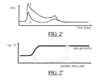
- FIG. 2a shows the diagram of the humidity (RH) course of two sensor modules at two different locations.
- the diagram shows that from the course of the humidity sensed by two sensor modules measured, after rainfall (sensed by the weather station 15) it can be concluded that, although the insulation layer at both pipeline locations have become wet, the insulation at location 1, sensed by sensor module 1, dries much slower than the insulation at location 2, represented by the humidity data sent by sensor 2.
- This information is interpreted by the processing system 6 as an area having a higher corrosion risk, which information can be displayed by the monitor.
- Figure 2b illustrates that, based on the local humidity at the various locations, water flux along the pipeline can be assessed.
- An important factor is the geometry of the pipeline: sensor modules located at the lower part of an ascending portion of the pipeline (shown left) may sense rather much humidity due to the fact that rain water penetrated into the insulation layer will flow towards the lower part in the ascending pipeline. However, if a rather high water flux is sensed in a horizontal portion of the pipeline (right in the figure) the processing system may conclude that such location contains a defect in the pipeline insulation, which is indicated as a location having higher corrosion risk.
- Figure 2c shows some temperature courses on the basis of which metal corrosion and/or coating degradation may be estimated by the processing system 6.
- the corrosion risk is higher at temperatures between about 50 - 90 °C, of course depending on the exposure times.
- the influences of the fluid temperature (course) inside the pipeline, the weather (rain, temperature, wind) are taken into account, on the basis of which the corrosion/degradation of the pipeline surface can be assessed by the processing means and displayed accordingly.
Landscapes
- Life Sciences & Earth Sciences (AREA)
- General Engineering & Computer Science (AREA)
- Engineering & Computer Science (AREA)
- Physics & Mathematics (AREA)
- Chemical & Material Sciences (AREA)
- Ecology (AREA)
- Environmental & Geological Engineering (AREA)
- Environmental Sciences (AREA)
- Mechanical Engineering (AREA)
- Health & Medical Sciences (AREA)
- Biodiversity & Conservation Biology (AREA)
- Analytical Chemistry (AREA)
- Biochemistry (AREA)
- General Health & Medical Sciences (AREA)
- General Physics & Mathematics (AREA)
- Immunology (AREA)
- Pathology (AREA)
- Testing Resistance To Weather, Investigating Materials By Mechanical Methods (AREA)
Abstract
Method and system for assessing corrosion and/or degradation of a pipeline for the transportation of any medium, comprising an array of local sensor modules over the length of the pipeline and arranged for measuring local temperature and humidity values at the pipeline and means for transmitting those values, along with sensor module identifiers, to processing means, as well as means for receiving the sensor module identifiers and local temperature and humidity values measured at the pipeline and inputting them into assessment means arranged for assessing local indicators related to the local corrosion and/or degradation of the pipeline. Wireless transmission means may be used for transmitting the values, along with the sensor module identifiers, to the processing means. The local sensor modules may comprise means for harvesting energy from sunlight and/or temperature differences between the pipeline and its environment.
Description
- The present invention concerns a method and system for assessing or predicting corrosion and/or degradation of a pipeline for the transportation of any medium.
- Corrosion of pipelines is a serious problem in industry which leads to large inspection and maintenance costs. One special difficulty is that many pipelines are surrounded by insulation material, in order to maintain the medium inside the pipe at its right temperature or reduce energy costs. Corrosion of the pipeline under the insulation layer is badly trendable, i.e. the corrosion is unpredictable in time, location and severeness. The reason of this is mainly that the environmental conditions to which the different parts of the pipeline are exposed, are unknown. In the present practice parts of the insulation at several locations insulation sheet of the pipeline is removed over a certain distance and the pipeline is inspected for corrosion. In practice 5 - 10% of the total pipe length appears to be affected, i.e. the metal may be corroded and/or the pipe coating, applied to the pipe for rust prevention, may be degraded. In general repair of the pipe by removing the rust and applying a new rust prevention coating is not highly effective as the corrosion tends to continue and the repair coating does not adhere very well to the affected pipe surface.
- One aim of the present invention is to provide a method and a system which will reduce the expensive and time consuming operations for inspecting (parts of) the pipeline.
- Another aim is to provide remote monitoring of the (estimated) corrosion of the pipe wall and/or degradation of its coating in an early stage or even still before it really started to occur.
- Yet another aim is an improved, more intensive coverage of the pipeline monitoring.
- Still another aim is to provide a mapping of the whole pipeline system and of its locations which need extra attention in view of metal corrosion or coating degradation.
- The invention is based on the understanding that it is not necessary to inspect the surface of the pipes for corrosion/degradation when some essential measuring values at or in the neighbourhood of the pipe surface could be measured, in particular the local temperature and the humidity, which values are used for assessment or estimation of the local pipe wall corrosion and/or pipe coating degradation, based on previously known corrosion/degradation (prediction/assessment) models.
- The method for assessing corrosion and/or degradation of a pipeline preferably comprises the following steps:
- providing an array of local sensor modules over the length of the pipeline, preferably at the pipeline's bottom area, the sensor modules being arranged for measuring local temperature and humidity values at the pipeline and transmitting those values, along with sensor module identifiers, to processing means;
- receiving said sensor module identifiers and local temperature and humidity values measured at the pipeline and inputting them into assessment means arranged for assessing local indicators related to the local corrosion and/or degradation of the pipeline.
- Although the local temperature and humidity values may, in general, be measured at or in the vicinity of the pipe wall (and pipe wall coating), in many cases the pipe will be surrounded by a layer of insulation material. In those cases the local sensor modules may be arranged to measure the local temperature and humidity values within the insulation material surrounding the pipeline.
- Besides, temperature values may be input into the assessment means, related to the medium flowing through the pipeline, as the (course of the) medium temperature (and thus of the pipeline wall) may improve the corrosion/degradation prediction model. Moreover, the temperature and humidity values related to the temperature and humidity outside the pipeline, e.g. due to the weather, may be input into the assessment means. Especially in areas at sea it may be preferred that the local sensor modules additionally are arranged to measure the chloride, ammonia, nitride contents and/or the contents of other potentially corrosive components, as in such areas such contents will be important factors for corrosion/degradation forming.
- A system for performing the method according to the invention preferably comprises an array of local sensor modules over the length of the pipeline and arranged for measuring local temperature and humidity values at the pipeline and means for transmitting those values, along with sensor module identifiers, to processing means, as well as and means for receiving the sensor module identifiers and local temperature and humidity values measured at the pipeline and inputting them into assessment means arranged for assessing local indicators related to the local corrosion and/or degradation of the pipeline.
- Preferably, the system comprises wireless transmission means for transmitting the temperature and humidity values, along with the sensor module identifiers, to the processing means.
- The local sensor modules may comprise or may be connected to means for harvesting energy from sunlight and/or any other light source and/or means for harvesting energy from temperature differences between the pipeline and its environment.
- Hereinafter the invention will be elucidated referencing to some figures.
- Figure 1
- shows part of an insulated pipe including a number of sensor modules and a processing module;
- Figures 2a-c
- illustrate known relationships between some input data and local pipeline corrosion/degradation rates.
- The configuration shown in
figure 1 is aimed at the assessment (or prediction) of corrosion and/or degradation of apipeline 1 for the transportation of anymedium 2. An array of local sensor modules 3 is provided over the length of thepipeline 1, which are arranged for measuring local temperature and humidity values, by means of a measuring probe 4, at the pipeline and transmitting, via a wireless path, represented byantennas 5, those values, along with sensor module identifiers for each sensor module, to aprocessing system 6. Theprocessing system 6 receives the sensor module identifiers and local temperature and humidity values measured at the pipeline and inputs them into a (software) assessment module which is arranged for assessing local indicators related to the local corrosion and/or degradation of the pipeline. - As can be seen in
figure 1 , thewall 7 of thepipeline 1 is surrounded by alayer 8 of insulation material which is covered by metalprotection sheet material 9, which is not watertight (so rain and snow may penetrate into the insulation layer 8). The local sensor modules 3 are arranged to measure the local temperature and humidity values within theinsulation material 8 surrounding thepipeline 1. As shown, the probes 4 are inserted through theprotection layer 9, and are thus capable to measure the temperature and humidity inside theinsulation layer 8 and to transmit the temperature and humidity values to theprocessing system 6 via theantennas 5. - The local sensor modules comprise means for harvesting energy from temperature differences between the pipeline and its environment, e.g. by means of Peltier elements which extend inside the
insulation layer 8 and outside theinsulation layer 8; due to the temperature difference inside and outside the Peltier element generates electricity for loading abattery 11, which is connected to feed a small local processor which collects and pre-processes the temperature and humidity values detected by the probe 4 and transmits them, including a (unique) module identifier, to theprocessing system 6, via a transmitter 13 and theantennas 5. - The local sensor modules may, besides, comprise, or be connected to, means for harvesting energy from sunlight and/or any other light source, i.e. small solar panels etc., which are not shown explicitly in
figure 1 . - In the
processing module 6 the measured temperature and humidity data are converted into (local) corrosion and/or degradation data, based on several presumptions. Except the temperature and humidity data, also the physical course of the pipeline may be considered in the assessments, e.g. the occurrence of curves, branches etc. in the pipeline, which can be extracted from apipeline management system 14 and/or sensor module positioning means which are discussed hereinafter. - Moreover, temperature values may be input into the assessment means, related to the fluid flowing through the pipeline, which temperature values may be derived from the
pipeline management system 14 and/or which can be measured at the pipeline itself at some locations. - Also temperature and humidity values related to the temperature and humidity outside the pipeline, e.g. due to the weather, may be input into the assessment means, e.g. by means of one or
more weather stations 15. - The local sensor modules may additionally be arranged to measure the chloride content, when the pipelines are located in the neighbourhood of the sea.
- In order to be able to process the locally sensed temperature and humidity values correctly the sensor modules should be linked to their individual locations. Two ways may be followed:
- One way is to link each sensor module identifier to its position, enabling that the processing means are capable to derive from the identifiers which received temperature/humidity data originate from which (sensor module) position. In this option the sensor module identifiers have to be linked initially, during installation of the sensor modules, to their global positions (e.g. determined by using a GPS receiver).
- Another way is to provide each sensor module with means for determining the sensor module's global position, e.g. a small GPS receiver, and transmitting that global position data to the processing means, together with or instead of the relevant sensor module's identifier and the temperature and humidity data. An alternative method is the use of radio direction finding (RDF)wherein, by combining the direction information from two or more suitably spaced receivers, the source of a transmission (in this case the sensor module transmitter) may be located in space via triangulation. In either case the temperature/humidity data are linked to their originating locations.
- All those data, the local temperature, humidity and, optionally, chloride content, the medium temperature inside the pipeline and the outside (environmental) temperature and humidity are determinative for the creation of (metal) corrosion and (coating) degradation. As most influences can be quantified by means of models which are implemented in the assessment software installed in the
processing module 6, the whole pipeline network can continuously be monitored and the assessed corrosion/degradation values (e.g. rates), together with their originating locations, can be displayed by amonitor 16, which is illustrated infigure 2 . - Finally some examples will be given, illustrated in
figures 2a - 2c of known relationships between several input data and metal corrosion and/or coating degradation rates. -
Figure 2a shows the diagram of the humidity (RH) course of two sensor modules at two different locations. The diagram shows that from the course of the humidity sensed by two sensor modules measured, after rainfall (sensed by the weather station 15) it can be concluded that, although the insulation layer at both pipeline locations have become wet, the insulation atlocation 1, sensed bysensor module 1, dries much slower than the insulation atlocation 2, represented by the humidity data sent bysensor 2. This information is interpreted by theprocessing system 6 as an area having a higher corrosion risk, which information can be displayed by the monitor. -
Figure 2b illustrates that, based on the local humidity at the various locations, water flux along the pipeline can be assessed. An important factor is the geometry of the pipeline: sensor modules located at the lower part of an ascending portion of the pipeline (shown left) may sense rather much humidity due to the fact that rain water penetrated into the insulation layer will flow towards the lower part in the ascending pipeline. However, if a rather high water flux is sensed in a horizontal portion of the pipeline (right in the figure) the processing system may conclude that such location contains a defect in the pipeline insulation, which is indicated as a location having higher corrosion risk. -
Figure 2c shows some temperature courses on the basis of which metal corrosion and/or coating degradation may be estimated by theprocessing system 6. In general the corrosion risk is higher at temperatures between about 50 - 90 °C, of course depending on the exposure times. In the assessment of corrosion/degradation based on the temperature and the humidity course in the pipeline insulation the influences of the fluid temperature (course) inside the pipeline, the weather (rain, temperature, wind) are taken into account, on the basis of which the corrosion/degradation of the pipeline surface can be assessed by the processing means and displayed accordingly.
Claims (11)
- Method for assessing corrosion and/or degradation of a pipeline for the transportation of any medium, the method comprising the following steps:- providing an array of local sensor modules over the length of the pipeline, arranged for measuring local temperature and humidity values at the pipeline and transmitting those values, along with sensor module identifiers, to processing means;- receiving said sensor module identifiers and local temperature and humidity values measured at the pipeline and inputting them into assessment means arranged for assessing local indicators related to the local corrosion and/or degradation of the pipeline.
- Method according to claim 1, the pipeline being surrounded by insulation material, wherein the local sensor modules are arranged to measure the local temperature and humidity values within the insulation material surrounding the pipeline.
- Method according to claim 1 or 2, wherein temperature values are input into the assessment means, related to the medium flowing through the pipeline.
- Method according to any preceding claim, wherein temperature and humidity values are input into the assessment means, related to the temperature and humidity outside the pipeline, e.g. due to the weather.
- Method according to any preceding claims, wherein the local sensor modules are arranged to measure the contents of potentially corrosive components like chloride, ammonia, nitride contents etc.
- System for assessing corrosion and/or degradation of a pipeline for the transportation of any medium, comprising an array of local sensor modules over the length of the pipeline and arranged for measuring local temperature and humidity values at the pipeline and means for transmitting those values, along with sensor module identifiers, to processing means;
and means for receiving said sensor module identifiers and local temperature and humidity values measured at the pipeline and inputting them into assessment means arranged for assessing local indicators related to the local corrosion and/or degradation of the pipeline. - System according to claim 6, comprising wireless transmission means for transmitting said values, along with said sensor module identifiers, to said processing means.
- System according to claim 6 or 7, the sensor module identifiers being linked to the relevant sensor module's position.
- System according to claim 6 or 7, the sensor module comprising means for determining the sensor module's geometrical position and inputting that position data to the processing means.
- System according to claim 6, said local sensor modules comprising or being connected to means for harvesting energy from sunlight or any other light source.
- System according to claim 6, said local sensor modules comprising or being connected to means for harvesting energy from temperature differences between the pipeline and its environment.
Priority Applications (3)
| Application Number | Priority Date | Filing Date | Title |
|---|---|---|---|
| EP09162281A EP2261546A1 (en) | 2009-06-09 | 2009-06-09 | Method and system for assessing corrosion and/or degradation of a pipeline |
| EP10728398.8A EP2440829B1 (en) | 2009-06-09 | 2010-06-08 | Method and system for assessing corrosion and/or degradation of a pipeline |
| PCT/NL2010/050348 WO2010143948A1 (en) | 2009-06-09 | 2010-06-08 | Method and system for assessing corrosion and/or degradation of a pipeline |
Applications Claiming Priority (1)
| Application Number | Priority Date | Filing Date | Title |
|---|---|---|---|
| EP09162281A EP2261546A1 (en) | 2009-06-09 | 2009-06-09 | Method and system for assessing corrosion and/or degradation of a pipeline |
Publications (1)
| Publication Number | Publication Date |
|---|---|
| EP2261546A1 true EP2261546A1 (en) | 2010-12-15 |
Family
ID=41202848
Family Applications (2)
| Application Number | Title | Priority Date | Filing Date |
|---|---|---|---|
| EP09162281A Withdrawn EP2261546A1 (en) | 2009-06-09 | 2009-06-09 | Method and system for assessing corrosion and/or degradation of a pipeline |
| EP10728398.8A Not-in-force EP2440829B1 (en) | 2009-06-09 | 2010-06-08 | Method and system for assessing corrosion and/or degradation of a pipeline |
Family Applications After (1)
| Application Number | Title | Priority Date | Filing Date |
|---|---|---|---|
| EP10728398.8A Not-in-force EP2440829B1 (en) | 2009-06-09 | 2010-06-08 | Method and system for assessing corrosion and/or degradation of a pipeline |
Country Status (2)
| Country | Link |
|---|---|
| EP (2) | EP2261546A1 (en) |
| WO (1) | WO2010143948A1 (en) |
Cited By (13)
| Publication number | Priority date | Publication date | Assignee | Title |
|---|---|---|---|---|
| CN103492780A (en) * | 2011-01-25 | 2014-01-01 | Rns技术有限公司 | Insulation composition and method to detect water in an insulation composition |
| WO2014081459A1 (en) * | 2012-11-22 | 2014-05-30 | Eaton Corporation | Energy harvesting circuit for life-sensing hose assembly |
| CN104359822A (en) * | 2014-10-23 | 2015-02-18 | 中国石油化工股份有限公司 | Corrosion simulation experiment device of coating below insulating layer |
| US9435709B2 (en) | 2011-04-29 | 2016-09-06 | Eaton Corporation | Degradation monitoring system for hose assembly |
| US9535024B2 (en) | 2012-09-14 | 2017-01-03 | Eaton Corporation | Sense and hold circuit for hose assembly |
| US9562822B2 (en) | 2013-02-22 | 2017-02-07 | Eaton Corporation | Flexible contact arrangement for hose assembly |
| US9643550B2 (en) | 2013-03-15 | 2017-05-09 | Eaton Corporation | Hose voltage carrier |
| US9677967B2 (en) | 2010-11-22 | 2017-06-13 | Eaton Corporation | Pressure-sensing hose |
| US9952170B2 (en) | 2012-04-23 | 2018-04-24 | Eaton Intelligent Power Limited | Methods and systems for measuring hose resistance |
| US10041844B1 (en) | 2017-04-07 | 2018-08-07 | International Business Machines Corporation | Fluid flow rate assessment by a non-intrusive sensor in a fluid transfer pump system |
| US10527205B2 (en) | 2012-09-14 | 2020-01-07 | Eaton Intelligent Power Limited | Wave contact arrangement for hose assembly |
| US10690548B2 (en) | 2017-04-07 | 2020-06-23 | International Business Machines Corporation | Environmental factor assessment by a non-intrusive sensor in a fluid transfer pumping system |
| US20220283079A1 (en) * | 2021-03-05 | 2022-09-08 | Dell Products, Lp | Assessment of humidity and non-humidity driven corrosion risk |
Families Citing this family (1)
| Publication number | Priority date | Publication date | Assignee | Title |
|---|---|---|---|---|
| CN116879149A (en) * | 2023-07-19 | 2023-10-13 | 中核核电运行管理有限公司 | Method and device for monitoring corrosion of insulating layer sewer chilled water pipeline based on optical fibers |
Citations (2)
| Publication number | Priority date | Publication date | Assignee | Title |
|---|---|---|---|---|
| WO2004109238A1 (en) * | 2003-06-06 | 2004-12-16 | M.B.T.L. Limited | Environmental sensor |
| WO2008102098A1 (en) * | 2007-02-23 | 2008-08-28 | Imperial Innovations Limited | Improved non-gps positioning systems |
Family Cites Families (1)
| Publication number | Priority date | Publication date | Assignee | Title |
|---|---|---|---|---|
| US7630864B2 (en) * | 2007-01-16 | 2009-12-08 | S&S X-Ray Products, Inc. | Temperature and humidity monitoring for pharmacy shipping crate |
-
2009
- 2009-06-09 EP EP09162281A patent/EP2261546A1/en not_active Withdrawn
-
2010
- 2010-06-08 WO PCT/NL2010/050348 patent/WO2010143948A1/en not_active Ceased
- 2010-06-08 EP EP10728398.8A patent/EP2440829B1/en not_active Not-in-force
Patent Citations (2)
| Publication number | Priority date | Publication date | Assignee | Title |
|---|---|---|---|---|
| WO2004109238A1 (en) * | 2003-06-06 | 2004-12-16 | M.B.T.L. Limited | Environmental sensor |
| WO2008102098A1 (en) * | 2007-02-23 | 2008-08-28 | Imperial Innovations Limited | Improved non-gps positioning systems |
Cited By (16)
| Publication number | Priority date | Publication date | Assignee | Title |
|---|---|---|---|---|
| US9677967B2 (en) | 2010-11-22 | 2017-06-13 | Eaton Corporation | Pressure-sensing hose |
| CN103492780B (en) * | 2011-01-25 | 2016-10-26 | Rns技术有限公司 | The method of the water in isolation compositions and detection isolation compositions |
| CN103492780A (en) * | 2011-01-25 | 2014-01-01 | Rns技术有限公司 | Insulation composition and method to detect water in an insulation composition |
| US9435709B2 (en) | 2011-04-29 | 2016-09-06 | Eaton Corporation | Degradation monitoring system for hose assembly |
| US9952170B2 (en) | 2012-04-23 | 2018-04-24 | Eaton Intelligent Power Limited | Methods and systems for measuring hose resistance |
| US9535024B2 (en) | 2012-09-14 | 2017-01-03 | Eaton Corporation | Sense and hold circuit for hose assembly |
| US10527205B2 (en) | 2012-09-14 | 2020-01-07 | Eaton Intelligent Power Limited | Wave contact arrangement for hose assembly |
| WO2014081459A1 (en) * | 2012-11-22 | 2014-05-30 | Eaton Corporation | Energy harvesting circuit for life-sensing hose assembly |
| US10024465B2 (en) | 2012-11-22 | 2018-07-17 | Eaton Intelligent Power Limited | Energy harvesting circuit for life-sensing hose assembly |
| US9562822B2 (en) | 2013-02-22 | 2017-02-07 | Eaton Corporation | Flexible contact arrangement for hose assembly |
| US9643550B2 (en) | 2013-03-15 | 2017-05-09 | Eaton Corporation | Hose voltage carrier |
| CN104359822A (en) * | 2014-10-23 | 2015-02-18 | 中国石油化工股份有限公司 | Corrosion simulation experiment device of coating below insulating layer |
| US10041844B1 (en) | 2017-04-07 | 2018-08-07 | International Business Machines Corporation | Fluid flow rate assessment by a non-intrusive sensor in a fluid transfer pump system |
| US10690548B2 (en) | 2017-04-07 | 2020-06-23 | International Business Machines Corporation | Environmental factor assessment by a non-intrusive sensor in a fluid transfer pumping system |
| US20220283079A1 (en) * | 2021-03-05 | 2022-09-08 | Dell Products, Lp | Assessment of humidity and non-humidity driven corrosion risk |
| US11579074B2 (en) * | 2021-03-05 | 2023-02-14 | Dell Products L.P. | Assessment of humidity and non-humidity driven corrosion risk |
Also Published As
| Publication number | Publication date |
|---|---|
| EP2440829A1 (en) | 2012-04-18 |
| WO2010143948A1 (en) | 2010-12-16 |
| EP2440829B1 (en) | 2016-03-23 |
Similar Documents
| Publication | Publication Date | Title |
|---|---|---|
| EP2440829B1 (en) | Method and system for assessing corrosion and/or degradation of a pipeline | |
| US10082478B2 (en) | Methods for evaluation and estimation of external corrosion damage on buried pipelines | |
| US8087311B2 (en) | Remote pipe inspection using a mounted camera and sensor | |
| US8893813B2 (en) | Fire protection sprinkler system with oxygen corrosion sensitive coupon assembly and method of monitoring corrosion in a fire protection sprinkler system | |
| US20160142160A1 (en) | Method of managing sensor network | |
| US20240377345A1 (en) | Method for early corrosion detection under insulation | |
| CN109448292A (en) | A kind of power grid mountain fire monitoring and pre-alarming method | |
| US20130037420A1 (en) | Method and apparatus for detecting moisture on metal and other surfaces, including surfaces under thermal insulation | |
| CN100399019C (en) | Underground Pipeline Corrosion and Leakage Intelligent Online Detection System | |
| EP3304065B1 (en) | Method for the prediction of leakage in a pipeline | |
| JP7287879B2 (en) | Corrosion detection system | |
| JP7595886B2 (en) | Frost damage risk assessment method | |
| CN113188053B (en) | Pipeline fault scheduling method, device and system based on pipeline geographical characteristics | |
| RU2262634C1 (en) | Method of detecting pipeline sections disposed to corrosion cracking under stressing | |
| JP2009097887A (en) | Leakage risk evaluation method for underground storage tank facility | |
| JP2008259313A (en) | Of cable abnormality detector, and method of detecting oil leakage from of cable | |
| CN109238951A (en) | A kind of corrosion testing device based on oil-gas pipeline | |
| US20240230389A9 (en) | Preventing frost damage of flow meters in a distribution network | |
| RU2599072C1 (en) | Device for in-tube flaw detection | |
| Corrao et al. | Condition assessment methods for 1920s lock-bar steel pipe | |
| Naganuma et al. | Investigation of Factors Affecting Corrosion Inner Steel Pipe for Transmission Tower | |
| EP4630788A1 (en) | Method and apparatus for monitoring corrosion under insulation | |
| Grytten et al. | RISK BASED SUBSEA INSPECTION PLANNING AND INTEGRITY MANAGEMENT BY USE OF FIGS® SENSOR | |
| Sens | Guided Wave CUI Inspection | |
| Chen et al. | Research advances in environmental corrosivity mapping techniques |
Legal Events
| Date | Code | Title | Description |
|---|---|---|---|
| PUAI | Public reference made under article 153(3) epc to a published international application that has entered the european phase |
Free format text: ORIGINAL CODE: 0009012 |
|
| AK | Designated contracting states |
Kind code of ref document: A1 Designated state(s): AT BE BG CH CY CZ DE DK EE ES FI FR GB GR HR HU IE IS IT LI LT LU LV MC MK MT NL NO PL PT RO SE SI SK TR |
|
| AX | Request for extension of the european patent |
Extension state: AL BA RS |
|
| STAA | Information on the status of an ep patent application or granted ep patent |
Free format text: STATUS: THE APPLICATION IS DEEMED TO BE WITHDRAWN |
|
| 18D | Application deemed to be withdrawn |
Effective date: 20110616 |