EP2261501A2 - Method and device for mounting a rotor blade for a wind energy plant - Google Patents
Method and device for mounting a rotor blade for a wind energy plant Download PDFInfo
- Publication number
- EP2261501A2 EP2261501A2 EP10005443A EP10005443A EP2261501A2 EP 2261501 A2 EP2261501 A2 EP 2261501A2 EP 10005443 A EP10005443 A EP 10005443A EP 10005443 A EP10005443 A EP 10005443A EP 2261501 A2 EP2261501 A2 EP 2261501A2
- Authority
- EP
- European Patent Office
- Prior art keywords
- shell
- web
- holding device
- movement
- webs
- Prior art date
- Legal status (The legal status is an assumption and is not a legal conclusion. Google has not performed a legal analysis and makes no representation as to the accuracy of the status listed.)
- Granted
Links
- 238000000034 method Methods 0.000 title claims abstract description 24
- 239000000853 adhesive Substances 0.000 claims abstract description 39
- 230000001070 adhesive effect Effects 0.000 claims abstract description 39
- 238000004519 manufacturing process Methods 0.000 description 4
- 239000011347 resin Substances 0.000 description 3
- 229920005989 resin Polymers 0.000 description 3
- 230000037303 wrinkles Effects 0.000 description 3
- 238000004026 adhesive bonding Methods 0.000 description 2
- 238000009434 installation Methods 0.000 description 2
- 230000003993 interaction Effects 0.000 description 2
- 230000014759 maintenance of location Effects 0.000 description 2
- 238000012805 post-processing Methods 0.000 description 2
- 239000000969 carrier Substances 0.000 description 1
- 230000006866 deterioration Effects 0.000 description 1
- 230000000694 effects Effects 0.000 description 1
- 239000004744 fabric Substances 0.000 description 1
- 239000011152 fibreglass Substances 0.000 description 1
- 239000011521 glass Substances 0.000 description 1
- 239000003365 glass fiber Substances 0.000 description 1
- 238000003384 imaging method Methods 0.000 description 1
- 238000001802 infusion Methods 0.000 description 1
- 238000002347 injection Methods 0.000 description 1
- 239000007924 injection Substances 0.000 description 1
- 239000007788 liquid Substances 0.000 description 1
- 239000000203 mixture Substances 0.000 description 1
- 230000000284 resting effect Effects 0.000 description 1
- 230000000452 restraining effect Effects 0.000 description 1
- 239000000126 substance Substances 0.000 description 1
- 238000009736 wetting Methods 0.000 description 1
Images


Classifications
-
- F—MECHANICAL ENGINEERING; LIGHTING; HEATING; WEAPONS; BLASTING
- F03—MACHINES OR ENGINES FOR LIQUIDS; WIND, SPRING, OR WEIGHT MOTORS; PRODUCING MECHANICAL POWER OR A REACTIVE PROPULSIVE THRUST, NOT OTHERWISE PROVIDED FOR
- F03D—WIND MOTORS
- F03D1/00—Wind motors with rotation axis substantially parallel to the air flow entering the rotor
- F03D1/06—Rotors
- F03D1/065—Rotors characterised by their construction elements
- F03D1/0675—Rotors characterised by their construction elements of the blades
-
- B—PERFORMING OPERATIONS; TRANSPORTING
- B29—WORKING OF PLASTICS; WORKING OF SUBSTANCES IN A PLASTIC STATE IN GENERAL
- B29D—PRODUCING PARTICULAR ARTICLES FROM PLASTICS OR FROM SUBSTANCES IN A PLASTIC STATE
- B29D99/00—Subject matter not provided for in other groups of this subclass
- B29D99/0025—Producing blades or the like, e.g. blades for turbines, propellers, or wings
- B29D99/0028—Producing blades or the like, e.g. blades for turbines, propellers, or wings hollow blades
-
- B—PERFORMING OPERATIONS; TRANSPORTING
- B29—WORKING OF PLASTICS; WORKING OF SUBSTANCES IN A PLASTIC STATE IN GENERAL
- B29C—SHAPING OR JOINING OF PLASTICS; SHAPING OF MATERIAL IN A PLASTIC STATE, NOT OTHERWISE PROVIDED FOR; AFTER-TREATMENT OF THE SHAPED PRODUCTS, e.g. REPAIRING
- B29C65/00—Joining or sealing of preformed parts, e.g. welding of plastics materials; Apparatus therefor
- B29C65/48—Joining or sealing of preformed parts, e.g. welding of plastics materials; Apparatus therefor using adhesives, i.e. using supplementary joining material; solvent bonding
- B29C65/4805—Joining or sealing of preformed parts, e.g. welding of plastics materials; Apparatus therefor using adhesives, i.e. using supplementary joining material; solvent bonding characterised by the type of adhesives
- B29C65/483—Reactive adhesives, e.g. chemically curing adhesives
-
- B—PERFORMING OPERATIONS; TRANSPORTING
- B29—WORKING OF PLASTICS; WORKING OF SUBSTANCES IN A PLASTIC STATE IN GENERAL
- B29C—SHAPING OR JOINING OF PLASTICS; SHAPING OF MATERIAL IN A PLASTIC STATE, NOT OTHERWISE PROVIDED FOR; AFTER-TREATMENT OF THE SHAPED PRODUCTS, e.g. REPAIRING
- B29C65/00—Joining or sealing of preformed parts, e.g. welding of plastics materials; Apparatus therefor
- B29C65/78—Means for handling the parts to be joined, e.g. for making containers or hollow articles, e.g. means for handling sheets, plates, web-like materials, tubular articles, hollow articles or elements to be joined therewith; Means for discharging the joined articles from the joining apparatus
- B29C65/7841—Holding or clamping means for handling purposes
-
- B—PERFORMING OPERATIONS; TRANSPORTING
- B29—WORKING OF PLASTICS; WORKING OF SUBSTANCES IN A PLASTIC STATE IN GENERAL
- B29C—SHAPING OR JOINING OF PLASTICS; SHAPING OF MATERIAL IN A PLASTIC STATE, NOT OTHERWISE PROVIDED FOR; AFTER-TREATMENT OF THE SHAPED PRODUCTS, e.g. REPAIRING
- B29C66/00—General aspects of processes or apparatus for joining preformed parts
- B29C66/01—General aspects dealing with the joint area or with the area to be joined
- B29C66/05—Particular design of joint configurations
- B29C66/301—Three-dimensional joints, i.e. the joined area being substantially non-flat
-
- B—PERFORMING OPERATIONS; TRANSPORTING
- B29—WORKING OF PLASTICS; WORKING OF SUBSTANCES IN A PLASTIC STATE IN GENERAL
- B29C—SHAPING OR JOINING OF PLASTICS; SHAPING OF MATERIAL IN A PLASTIC STATE, NOT OTHERWISE PROVIDED FOR; AFTER-TREATMENT OF THE SHAPED PRODUCTS, e.g. REPAIRING
- B29C66/00—General aspects of processes or apparatus for joining preformed parts
- B29C66/50—General aspects of joining tubular articles; General aspects of joining long products, i.e. bars or profiled elements; General aspects of joining single elements to tubular articles, hollow articles or bars; General aspects of joining several hollow-preforms to form hollow or tubular articles
- B29C66/51—Joining tubular articles, profiled elements or bars; Joining single elements to tubular articles, hollow articles or bars; Joining several hollow-preforms to form hollow or tubular articles
- B29C66/52—Joining tubular articles, bars or profiled elements
- B29C66/524—Joining profiled elements
-
- B—PERFORMING OPERATIONS; TRANSPORTING
- B29—WORKING OF PLASTICS; WORKING OF SUBSTANCES IN A PLASTIC STATE IN GENERAL
- B29C—SHAPING OR JOINING OF PLASTICS; SHAPING OF MATERIAL IN A PLASTIC STATE, NOT OTHERWISE PROVIDED FOR; AFTER-TREATMENT OF THE SHAPED PRODUCTS, e.g. REPAIRING
- B29C66/00—General aspects of processes or apparatus for joining preformed parts
- B29C66/50—General aspects of joining tubular articles; General aspects of joining long products, i.e. bars or profiled elements; General aspects of joining single elements to tubular articles, hollow articles or bars; General aspects of joining several hollow-preforms to form hollow or tubular articles
- B29C66/51—Joining tubular articles, profiled elements or bars; Joining single elements to tubular articles, hollow articles or bars; Joining several hollow-preforms to form hollow or tubular articles
- B29C66/53—Joining single elements to tubular articles, hollow articles or bars
- B29C66/532—Joining single elements to the wall of tubular articles, hollow articles or bars
-
- B—PERFORMING OPERATIONS; TRANSPORTING
- B29—WORKING OF PLASTICS; WORKING OF SUBSTANCES IN A PLASTIC STATE IN GENERAL
- B29C—SHAPING OR JOINING OF PLASTICS; SHAPING OF MATERIAL IN A PLASTIC STATE, NOT OTHERWISE PROVIDED FOR; AFTER-TREATMENT OF THE SHAPED PRODUCTS, e.g. REPAIRING
- B29C66/00—General aspects of processes or apparatus for joining preformed parts
- B29C66/50—General aspects of joining tubular articles; General aspects of joining long products, i.e. bars or profiled elements; General aspects of joining single elements to tubular articles, hollow articles or bars; General aspects of joining several hollow-preforms to form hollow or tubular articles
- B29C66/51—Joining tubular articles, profiled elements or bars; Joining single elements to tubular articles, hollow articles or bars; Joining several hollow-preforms to form hollow or tubular articles
- B29C66/54—Joining several hollow-preforms, e.g. half-shells, to form hollow articles, e.g. for making balls, containers; Joining several hollow-preforms, e.g. half-cylinders, to form tubular articles
-
- B—PERFORMING OPERATIONS; TRANSPORTING
- B29—WORKING OF PLASTICS; WORKING OF SUBSTANCES IN A PLASTIC STATE IN GENERAL
- B29C—SHAPING OR JOINING OF PLASTICS; SHAPING OF MATERIAL IN A PLASTIC STATE, NOT OTHERWISE PROVIDED FOR; AFTER-TREATMENT OF THE SHAPED PRODUCTS, e.g. REPAIRING
- B29C66/00—General aspects of processes or apparatus for joining preformed parts
- B29C66/50—General aspects of joining tubular articles; General aspects of joining long products, i.e. bars or profiled elements; General aspects of joining single elements to tubular articles, hollow articles or bars; General aspects of joining several hollow-preforms to form hollow or tubular articles
- B29C66/61—Joining from or joining on the inside
-
- B—PERFORMING OPERATIONS; TRANSPORTING
- B29—WORKING OF PLASTICS; WORKING OF SUBSTANCES IN A PLASTIC STATE IN GENERAL
- B29C—SHAPING OR JOINING OF PLASTICS; SHAPING OF MATERIAL IN A PLASTIC STATE, NOT OTHERWISE PROVIDED FOR; AFTER-TREATMENT OF THE SHAPED PRODUCTS, e.g. REPAIRING
- B29C66/00—General aspects of processes or apparatus for joining preformed parts
- B29C66/50—General aspects of joining tubular articles; General aspects of joining long products, i.e. bars or profiled elements; General aspects of joining single elements to tubular articles, hollow articles or bars; General aspects of joining several hollow-preforms to form hollow or tubular articles
- B29C66/63—Internally supporting the article during joining
- B29C66/636—Internally supporting the article during joining using a support which remains in the joined object
-
- B—PERFORMING OPERATIONS; TRANSPORTING
- B29—WORKING OF PLASTICS; WORKING OF SUBSTANCES IN A PLASTIC STATE IN GENERAL
- B29C—SHAPING OR JOINING OF PLASTICS; SHAPING OF MATERIAL IN A PLASTIC STATE, NOT OTHERWISE PROVIDED FOR; AFTER-TREATMENT OF THE SHAPED PRODUCTS, e.g. REPAIRING
- B29C66/00—General aspects of processes or apparatus for joining preformed parts
- B29C66/70—General aspects of processes or apparatus for joining preformed parts characterised by the composition, physical properties or the structure of the material of the parts to be joined; Joining with non-plastics material
- B29C66/72—General aspects of processes or apparatus for joining preformed parts characterised by the composition, physical properties or the structure of the material of the parts to be joined; Joining with non-plastics material characterised by the structure of the material of the parts to be joined
- B29C66/721—Fibre-reinforced materials
- B29C66/7212—Fibre-reinforced materials characterised by the composition of the fibres
-
- B—PERFORMING OPERATIONS; TRANSPORTING
- B29—WORKING OF PLASTICS; WORKING OF SUBSTANCES IN A PLASTIC STATE IN GENERAL
- B29C—SHAPING OR JOINING OF PLASTICS; SHAPING OF MATERIAL IN A PLASTIC STATE, NOT OTHERWISE PROVIDED FOR; AFTER-TREATMENT OF THE SHAPED PRODUCTS, e.g. REPAIRING
- B29C66/00—General aspects of processes or apparatus for joining preformed parts
- B29C66/80—General aspects of machine operations or constructions and parts thereof
- B29C66/83—General aspects of machine operations or constructions and parts thereof characterised by the movement of the joining or pressing tools
- B29C66/832—Reciprocating joining or pressing tools
- B29C66/8322—Joining or pressing tools reciprocating along one axis
-
- B—PERFORMING OPERATIONS; TRANSPORTING
- B29—WORKING OF PLASTICS; WORKING OF SUBSTANCES IN A PLASTIC STATE IN GENERAL
- B29C—SHAPING OR JOINING OF PLASTICS; SHAPING OF MATERIAL IN A PLASTIC STATE, NOT OTHERWISE PROVIDED FOR; AFTER-TREATMENT OF THE SHAPED PRODUCTS, e.g. REPAIRING
- B29C66/00—General aspects of processes or apparatus for joining preformed parts
- B29C66/90—Measuring or controlling the joining process
- B29C66/92—Measuring or controlling the joining process by measuring or controlling the pressure, the force, the mechanical power or the displacement of the joining tools
- B29C66/924—Measuring or controlling the joining process by measuring or controlling the pressure, the force, the mechanical power or the displacement of the joining tools by controlling or regulating the pressure, the force, the mechanical power or the displacement of the joining tools
- B29C66/9261—Measuring or controlling the joining process by measuring or controlling the pressure, the force, the mechanical power or the displacement of the joining tools by controlling or regulating the pressure, the force, the mechanical power or the displacement of the joining tools by controlling or regulating the displacement of the joining tools
- B29C66/92651—Measuring or controlling the joining process by measuring or controlling the pressure, the force, the mechanical power or the displacement of the joining tools by controlling or regulating the pressure, the force, the mechanical power or the displacement of the joining tools by controlling or regulating the displacement of the joining tools by using stops
-
- B—PERFORMING OPERATIONS; TRANSPORTING
- B29—WORKING OF PLASTICS; WORKING OF SUBSTANCES IN A PLASTIC STATE IN GENERAL
- B29L—INDEXING SCHEME ASSOCIATED WITH SUBCLASS B29C, RELATING TO PARTICULAR ARTICLES
- B29L2031/00—Other particular articles
- B29L2031/08—Blades for rotors, stators, fans, turbines or the like, e.g. screw propellers
- B29L2031/082—Blades, e.g. for helicopters
- B29L2031/085—Wind turbine blades
-
- Y—GENERAL TAGGING OF NEW TECHNOLOGICAL DEVELOPMENTS; GENERAL TAGGING OF CROSS-SECTIONAL TECHNOLOGIES SPANNING OVER SEVERAL SECTIONS OF THE IPC; TECHNICAL SUBJECTS COVERED BY FORMER USPC CROSS-REFERENCE ART COLLECTIONS [XRACs] AND DIGESTS
- Y02—TECHNOLOGIES OR APPLICATIONS FOR MITIGATION OR ADAPTATION AGAINST CLIMATE CHANGE
- Y02E—REDUCTION OF GREENHOUSE GAS [GHG] EMISSIONS, RELATED TO ENERGY GENERATION, TRANSMISSION OR DISTRIBUTION
- Y02E10/00—Energy generation through renewable energy sources
- Y02E10/70—Wind energy
- Y02E10/72—Wind turbines with rotation axis in wind direction
-
- Y—GENERAL TAGGING OF NEW TECHNOLOGICAL DEVELOPMENTS; GENERAL TAGGING OF CROSS-SECTIONAL TECHNOLOGIES SPANNING OVER SEVERAL SECTIONS OF THE IPC; TECHNICAL SUBJECTS COVERED BY FORMER USPC CROSS-REFERENCE ART COLLECTIONS [XRACs] AND DIGESTS
- Y02—TECHNOLOGIES OR APPLICATIONS FOR MITIGATION OR ADAPTATION AGAINST CLIMATE CHANGE
- Y02P—CLIMATE CHANGE MITIGATION TECHNOLOGIES IN THE PRODUCTION OR PROCESSING OF GOODS
- Y02P70/00—Climate change mitigation technologies in the production process for final industrial or consumer products
- Y02P70/50—Manufacturing or production processes characterised by the final manufactured product
-
- Y—GENERAL TAGGING OF NEW TECHNOLOGICAL DEVELOPMENTS; GENERAL TAGGING OF CROSS-SECTIONAL TECHNOLOGIES SPANNING OVER SEVERAL SECTIONS OF THE IPC; TECHNICAL SUBJECTS COVERED BY FORMER USPC CROSS-REFERENCE ART COLLECTIONS [XRACs] AND DIGESTS
- Y10—TECHNICAL SUBJECTS COVERED BY FORMER USPC
- Y10T—TECHNICAL SUBJECTS COVERED BY FORMER US CLASSIFICATION
- Y10T156/00—Adhesive bonding and miscellaneous chemical manufacture
- Y10T156/10—Methods of surface bonding and/or assembly therefor
- Y10T156/1089—Methods of surface bonding and/or assembly therefor of discrete laminae to single face of additional lamina
-
- Y—GENERAL TAGGING OF NEW TECHNOLOGICAL DEVELOPMENTS; GENERAL TAGGING OF CROSS-SECTIONAL TECHNOLOGIES SPANNING OVER SEVERAL SECTIONS OF THE IPC; TECHNICAL SUBJECTS COVERED BY FORMER USPC CROSS-REFERENCE ART COLLECTIONS [XRACs] AND DIGESTS
- Y10—TECHNICAL SUBJECTS COVERED BY FORMER USPC
- Y10T—TECHNICAL SUBJECTS COVERED BY FORMER US CLASSIFICATION
- Y10T156/00—Adhesive bonding and miscellaneous chemical manufacture
- Y10T156/17—Surface bonding means and/or assemblymeans with work feeding or handling means
Definitions
- the invention relates to a method and a device for mounting a rotor blade for a wind energy plant, which has a first half shell, a second half shell and at least one web extending in the longitudinal direction of the rotor blade.
- Rotor blades of wind turbines are exposed to very high and varying loads.
- the strength and aerodynamic quality of the rotor blades depends in particular on rotor blades, which are assembled from two half-shells, substantially from the exact and safe installation of said components.
- Upper and lower shell of such rotor blades are usually made of glass fiber reinforced plastic and are glued together, inter alia, at their front and rear edges. Between the upper and lower shell is often a web or more, in particular parallel webs, which are connected to the lower shell and the upper shell and give the rotor blade additional strength.
- the web or webs form a support unit in conjunction with the main belts running along the shell halves.
- the lower shell of the rotor blade is first arranged in an upwardly open shape or on a suitable frame, so that its inner side faces upwards.
- adhesive is applied to the lower shell.
- the web or the webs are lowered with a suitable hoist at the desired position on the lower shell until they rest on the lower shell.
- adhesive is applied in the connection region between the shell halves and in the connection region between the web or the webs and the upper shell and the Upper shell is placed on the bridge or the webs and the lower shell and glued to these.
- the invention is based on the recognition that the known from the prior art settling of the web on the lower shell often leads to an inaccurate positioning of the web.
- the reason for this are dimensional deviations in the inner contour of the lower shell.
- the half-shells of the rotor blades are usually made in open molds either by inserting already impregnated with resin glass shelves, so-called prepregs, or by a dry layer structure of Glasgelegen with subsequent infusion or injection of a resin.
- the layer structure is covered airtight with a film and the air is evacuated. The now compared to the internal pressure under the film greater atmospheric pressure compresses the scrim layers together, thus ensuring a high density of the resulting laminate.
- the web sinks at different depths into the applied adhesive under its own weight.
- the web With relatively liquid adhesive, the web usually sinks down to the inner contour of the rotor blade.
- the web can also tilt in the longitudinal and / or transverse direction, which leads to errors in the positioning of the web and in consequence to large variations in the thickness and geometry of the adhesive joint.
- Deviations in the positioning of the web on the lower shell can lead to significant inaccuracies in the connection with the upper shell.
- the problems mentioned require a complicated post-processing of the glued joints of the respective rotor blade, which may not be possible after placing the upper shell under certain circumstances.
- the control or post-processing of the adhesive bonds after the bonding of the sheet is only limited possible.
- the first half shell may be the lower shell and the second half shell may be the upper shell of the rotor blade, or vice versa.
- Arranging the first Half shell can be made, for example, by means of a mold used for the production of the half-shell or other carrying or holding device, hereinafter referred to as a receiving device, which receives the first half-shell in a predetermined position and holds in this.
- the first half-shell can be arranged so that its inside faces upwards.
- the fastening of the at least one web to the web holding device can be carried out in particular by means of a suitable fastening device of the web holding device, with which the at least one web is detachably fastened in the web holding device.
- the attachment can be made so that the at least one web is fixed with respect to the web holding device in a predetermined position and angular position.
- the adhesive is arranged in the connection region between the first half-shell and the at least one web. For example, it can be applied to the inside of the first half shell.
- the adhesive in the connecting region between the second half-shell and the at least one web can be applied, for example, on the surface of the at least one web facing the second half-shell or on the inside of the second half-shell.
- the arrangement of the second half-shell in a predetermined position can be done for example by means of a crane; It is also conceivable to use a separate device with which the second half-shell is brought into the predetermined position, for example by pivoting the second half-shell about a pivot axis extending parallel to its longitudinal direction. To bring the second half-shell in its desired position, this can with an additional force be applied downward, for example by a positioning device for the second half-shell or a Form-Sch Strukturvornchtung. The movement of the second half-shell downwards may preferably take place into an end position which can be predetermined by at least one further stop.
- connection of the two half-shells can be effected in particular by gluing along the front and rear edges of the two half-shells.
- the movement of the bar holding device with the thereto attached, at least one web in the direction of the first half-shell takes place up to an end position.
- the end position is determined by a movement limiting device which limits the movement so that, in the end position, the at least one web is arranged along its entire length at a distance from the first half-shell.
- the end position can be defined, for example, with respect to a center or symmetry axis of the rotor blade, so that the at least one web is kept "floating" at a distance from the first half shell and with respect to both the first and the second half shell in its desired position.
- the movement limiting device can be, for example, a mechanical stop, but it is also possible to limit the movement by means of a control which controls the movement when a predefinable end position is reached stops, for example, by controlling a movement performing adjustment.
- the movement limiting device of the adjusting device can specify a desired value that defines the end position.
- the at least one movement limiting device is adjustable.
- a serving as a movement limiting device stop and / or cooperating with the stop counterpart, such as a defined contact surface be adjustable so that the end position of the web can be adjusted according to its desired position.
- the web After curing of the adhesive in the connecting region between the first half-shell and the at least one web, the web is thus exactly in this position, so that the desired distance is maintained exactly between the at least one web and the second half-shell.
- the loosening and removal of the web holding device is preferably carried out after complete curing of the adhesive.
- the at least one movement limiting device is designed as a stop on the web holding device and interacts with the shell edge of the first half shell and / or with a holding device for the first half shell holding the first half shell in its predetermined position.
- the stop can be designed in any way, as long as it limits the movement of the web.
- at least one stop may be formed on the at least one web or on the first half shell, which limits the relative movement between web and half shell in the end position in which it comes into contact with the respective other component.
- the at least one stop is preferably designed such that it becomes effective independently of the manufacturing tolerances of the inner contour of the first half shell.
- At least one stop acting independently of the presence of the first half-shell and / or the presence of the at least one web can be used which limits the movement of a first component of the device relative to a second component of the device.
- the at least one stop is arranged on the web holding device and cooperates with a receiving device for the first half-shell.
- the receiving device may have defined contact areas which come into contact with the stops of the web holding device.
- a contact between arranged on the web holding device stops and the first half-shell itself may be provided.
- an area of the first half shell is preferably selected as the contact surface for the stops, which has relatively low manufacturing tolerances, in particular suitable shell edge portions of the first half shell. It is also possible to cooperate with respect to the web holding device fixedly arranged stop with any fixed counterpart.
- the web restraining device with the at least one web attached thereto is disposed in a predetermined position at a distance from the first half shell prior to moving to the end position and the movement of the web support device is guided so that the direction of movement and the relative angular position of the at least one Stegs with respect to the first half-shell is predetermined.
- the predetermined position can be next to or above the first half-shell.
- other predefined positions are possible.
- the at least one web is in this embodiment during the movement in a well-defined position and angular position. A tilting or slipping of the at least one web relative to the first half-shell during the movement and in the end position is thereby excluded. It is characterized a much more accurate positioning of the at least one web opposite the half shell allows, and the final position is achieved particularly reliable.
- the guiding of the movement in a predetermined direction can in particular be designed so that a return movement in the opposite direction is not possible. Otherwise, removal of the web from the first half shell can easily lead to deterioration of the adhesive bond. This problem often occurs in the prior art method when a positioning error of the web is detected and an attempt is made to correct the position. If a return movement of the web is excluded in the invention, this problem can not occur even if a return movement of the web was not intended.
- a rotor blade having a plurality of longitudinally extending webs
- all or individual webs attached to the web holding device, wherein the position of each web with respect to the web holding device and with respect to the half-shells is fixed by the attachment.
- the rotor blade may have two, three or more webs.
- the webs can also be connected to each other. Due to the defined fastening of all the webs on the web holding device, the already explained advantages are achieved simultaneously with the use of a plurality of webs for each individual web.
- the load handling equipment For example, screws or bolts can be used which cooperate with holes or other openings as load receiving points on the web holding device.
- the targeted interaction of load-receiving means and load-receiving points ensures that the at least one web is automatically in its desired position with respect to the web holding device after attachment to the web holding device.
- the load-receiving means each have a cone, which cooperates with a conical opening on one of the load-receiving points, or vice versa.
- the interaction of the conical surfaces an automatic centering is achieved, which leads to a particularly accurate positioning of the at least one web with respect to the Steghaltevornchtung.
- the load receiving means may also have otherwise appropriately shaped recordings, which cooperate with correspondingly shaped openings at the load receiving points.
- the movement of the bar holding device with the thereto attached, at least one web in the direction of the first half-shell takes place with the aid of lowering devices, which lower the bar holding device relative to the first half-shell.
- the lowering devices may be, for example, hydraulic cylinders, pneumatically operated cylinders or electrically / mechanically driven adjusting devices.
- hydraulic or pneumatic cylinders provision can be made, in particular, for the lowering to take place by opening a valve, which allows the pressure medium to escape from the cylinder. In this case, an accidental retraction of the web holding device with the web attached thereto is automatically prevented, because this would require a pressure medium supply into the respective cylinder.
- the at least one movement limiting device is formed on the lowering devices such that it limits an adjustment path of the lowering devices. Also, this movement limiting device is preferably adjustable, so that the end position can be precisely specified by appropriately limiting the maximum Absenkweges the lowering devices.
- the lowering devices form supports on which the bar holding device is lowered before the bar holding device is lowered by means of the lowering devices.
- the web retention device may have defined abutments which cooperate with the supports.
- the supports can also be located on a stationary device.
- the height of the support points then corresponds to the predetermined lowering position of the webs.
- the ridge holding device is lowered by means of a crane or other suitable working means.
- the bar holding device can also by means of a pivoting movement about an axis extending in the longitudinal direction of the Steghaltevorrichung axis on the supports be put on. Also conceivable is a combination of pan and translational movement.
- the movement device has a guide for specifying the direction of movement and relative angular position of the web holding device with respect to the receiving device for the first half-shell.
- the at least one movement limiting device is preferably formed on the guide.
- the movement limiting device may for example be part of a lowering device, for example in the form of a travel limit of a piston, or a separate mechanical device which limits the movement of the web holding device.
- the movement limiting device is preferably effective independently of components of the rotor blade in the device. Preferably, it is designed to be adjustable, so that the end position can be adapted to the particular circumstances.
- Fig. 1a shows a first half-shell 10 of a rotor blade, which is arranged in a receiving device, not shown, or in the open mold used for the production of the half-shell. It is located in a predetermined position above the bottom 12 of an assembly hall, wherein the inside of the first half-shell 10 faces upward. Dashed lines show a dividing plane 14 of the rotor blade, which extends from the rotor blade leading edge to the rotor blade trailing edge.
- the first half-shell 10 has on the inside a main belt 16 which reinforces the first half-shell.
- a lowering device 18 consisting of a hydraulic cylinder 20 and a piston 22 is arranged on both sides of the first half-shell 10 is in each case a lowering device 18 consisting of a hydraulic cylinder 20 and a piston 22 is arranged.
- the lowering devices 18 are mounted on the floor 12 of the assembly hall.
- Fig. 1c additionally shows the bar holding device 26 which has a cross member 28 and further supports 30 protruding downwardly therefrom. Between the two other carriers 30 are two webs 32 of the rotor blade. The webs 32 have along their two half-shells facing longitudinal edges angled mounting portions 36 which allow a large-area contact in the connecting region with the two half-shells.
- the cross member 28 has in the region of its two ends in each case a non-illustrated abutment which rests on corresponding supports on the piston 22 of the two lowering devices 18.
- the cross member 28 preferably extends horizontally at a right angle to the longitudinal direction of the first half shell 10 and the two webs 32nd
- the movement takes place until a predetermined by at least one stop 23, which is a movement limiting device, predetermined end position is reached, which in the Fig. 1d ) is shown.
- the stopper 23 is fixedly arranged with respect to the web holding device 26 and cooperates with a stationary counterpart 34 standing on the ground 12.
- the webs 32 are in a position defined with respect to the parting plane 14 and at a distance from the first half shell 10. They are in contact with the adhesive 24 and are suspended above the inner contour of the first half shell 10.
- the defined distance and the precisely maintained desired geometry ensures a high-strength and adhesive-saving bonding between the webs 32 and the first half-shell 10 and the main belt 16, respectively.
- the web-holding device 26 is released from the webs 32 and removed. This condition is in the Fig. 1e ) illustrated. The two webs 32 are after completion of the guided movement of the web holding device 26 still in the exact predetermined end position.
- adhesive is applied to the upper angled mounting portions 36 of the webs 32, and the second half-shell 38 is placed by means of a suitable device. After curing of the adhesive, it is firmly connected to the two webs 32.
- a connection between the first half-shell 10 and the second half-shell 38 in particular also by gluing in the region of the contact surfaces.
- the second half-shell 38 also has a main belt 40 which extends longitudinally along the inside of the first half-shell 10.
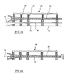
- FIGS. 2a) and 2b ) show a sectional view of the side view of the bar holding device according to the invention as shown in the Figures 1c) and 1d ).
- Fig. 2a is the web holding device 26 with the attached webs 32 in a predetermined position, wherein between the webs 32 and the first half-shell 10, a relatively large distance remains. Starting from this position, lowering the bar holding device 26 by opening a valve of the hydraulic cylinder 20. The bar holding device 26 with the webs attached thereto 32 moves to the first half-shell 10, because of the guide formed by the lowering 18 while adhering to a fixed predetermined direction of movement, in the example shown vertically downwards, and in compliance with a defined angular position.
- the movement takes place until a predetermined by at least one stop end position is reached, which in the Fig. 2b ) is shown.
- the webs 32 are in a position defined with respect to the parting plane 14. It is clearly recognizable here that the web is not deposited on the first half-shell, but is positioned at a distance h from the first half-shell 10.
- FIGS. 3a) and 3b ) show a cross section through a rotor blade with incorrectly inserted webs 32, wherein for the installation of the webs 32 not the inventive method was used.
- Fig. 3a are the webs 32 sunken due to a low viscosity of the adhesive under its own weight in the applied adhesive until it is on the main belt 16 of the first Half shell 10 rest. In these contact areas, the adhesive is almost completely displaced, and there is no sufficient cohesive connection between web 32 and main belt 16.
- the resulting between the webs 32 and the main belt 40 of the second half-shell 38 height difference is by an oversized adhesive application 24 between the webs 32 and the second half-shell 38 balanced.
- the Fig. 3b shows a section through a rotor blade, in which the main belt 16 of the first blade half shell 10 has a one-sided shaft 17. Through this shaft 17, the punctiform resting web 32.1 tilts in the longitudinal direction and receives a higher position with respect to the parting plane 14.
- the second web 32.2 was placed in a belt region with normal cross-section, but is sunk to the main belt 16.
- the attachment portions 36.1, 36.2 of the webs 32.1, 32.2 thereby have a different distance to the parting plane 14.
- the second half-shell 38 is pulled down when placed on the first half-shell 10 by means of a form-closure device, not shown, whereby the applied to the mounting portion 36.1 of the first web adhesive is displaced.
- the Fig. 3c shows a cross section through a rotor blade with webs 32 used according to the method / device according to the invention.
- the webs 32 are located in a precisely defined position relative to the parting plane 14 and thus at a distance from the first and second half-shell 10, 38.
Abstract
Description
Die Erfindung betrifft ein Verfahren und eine Vorrichtung zur Montage eines Rotorblatts für eine Windenergieanlage, das eine erste Halbschale, eine zweite Halbschale und mindestens einen in Längsrichtung des Rotorblatts verlaufenden Steg aufweist.The invention relates to a method and a device for mounting a rotor blade for a wind energy plant, which has a first half shell, a second half shell and at least one web extending in the longitudinal direction of the rotor blade.
Rotorblätter von Windenergieanlagen sind sehr hohen und wechselnden Belastungen ausgesetzt. Die Festigkeit und aerodynamische Qualität der Rotorblätter hängt insbesondere bei Rotorblättern, die aus zwei Halbschalen zusammengefügt werden, wesentlich von der exakten und sicheren Montage der genannten Komponenten ab. Ober- und Unterschale derartiger Rotorblätter bestehen zumeist aus glasfaserverstärktem Kunststoff und werden unter anderem an ihren Vorder- und Hinterkanten umlaufend miteinander verklebt. Zwischen Ober- und Unterschale befindet sich häufig ein Steg oder auch mehrere insbesondere parallel angeordnete Stege, die mit der Unterschale und der Oberschale verbunden sind und dem Rotorblatt zusätzliche Festigkeit verleihen. Der oder die Stege bilden in Verbindung mit den längs der Schalenhälften verlaufenden Hauptgurten eine Trageinheit.Rotor blades of wind turbines are exposed to very high and varying loads. The strength and aerodynamic quality of the rotor blades depends in particular on rotor blades, which are assembled from two half-shells, substantially from the exact and safe installation of said components. Upper and lower shell of such rotor blades are usually made of glass fiber reinforced plastic and are glued together, inter alia, at their front and rear edges. Between the upper and lower shell is often a web or more, in particular parallel webs, which are connected to the lower shell and the upper shell and give the rotor blade additional strength. The web or webs form a support unit in conjunction with the main belts running along the shell halves.
Bei einem bekannten Montageverfahren wird zunächst die Unterschale des Rotorblatts in einer nach oben offenen Form oder auf einem geeigneten Gestell angeordnet, so dass ihre Innenseite nach oben weist. Im Verbindungsbereich zwischen der Unterschale und dem Steg bzw. den Stegen wird Klebstoff auf die Unterschale aufgetragen. Anschließend wird der Steg bzw. werden die Stege mit einem geeigneten Hebezeug an der gewünschten Position auf die Unterschale abgesenkt, bis sie auf der Unterschale aufliegen. Anschließend wird Klebstoff im Verbindungsbereich zwischen den Schalenhälften und im Verbindungsbereich zwischen dem Steg bzw. den Stegen und der Oberschale aufgetragen und die Oberschale wird auf den Steg bzw. die Stege und die Unterschale aufgesetzt und mit diesen verklebt.In a known assembly method, the lower shell of the rotor blade is first arranged in an upwardly open shape or on a suitable frame, so that its inner side faces upwards. In the connection area between the lower shell and the web or webs adhesive is applied to the lower shell. Subsequently, the web or the webs are lowered with a suitable hoist at the desired position on the lower shell until they rest on the lower shell. Subsequently, adhesive is applied in the connection region between the shell halves and in the connection region between the web or the webs and the upper shell and the Upper shell is placed on the bridge or the webs and the lower shell and glued to these.
Davon ausgehend ist es die Aufgabe der Erfindung, ein verbessertes Verfahren zur Montage eines Rotorblatts für eine Windenergieanlage zur Verfügung zu stellen, das eine gleichmäßige und vorgabegerechte Dimensionierung der Klebeverbindungen von Steg oder Stegen mit den in die Hauptschale integrierten Hauptgurten bei gleichzeitig geringerem Klebstoffverbrauch ermöglicht, sowie eine Vorrichtung zur Durchführung des Verfahrens.On this basis, it is the object of the invention to provide an improved method for mounting a rotor blade for a wind turbine, which allows a uniform and default dimensioning of the adhesive joints of web or webs with the integrated into the main shell main straps at the same time lower adhesive consumption, and a device for carrying out the method.
Die Erfindung beruht auf der Erkenntnis, dass das aus dem Stand der Technik bekannte Absetzen des Steges auf der Unterschale häufig zu einer ungenauen Positionierung des Stegs führt. Ursache hierfür sind maßliche Abweichungen in der Innenkontur der Unterschale. Die Halbschalen der Rotorblätter werden in der Regel in offenen Formen entweder durch Einlegen von bereits mit Harz getränkten Glasgelegen, sogenannten Prepregs, oder durch einen trockenen Lagenaufbau aus Glasgelegen mit anschließender Infusion oder Injektion eines Harzes gefertigt. Der Lagenaufbau wird mit einer Folie luftdicht abgedeckt und die Luft wird evakuiert. Der nun gegenüber dem Innendruck unter der Folie größere atmosphärische Luftdruck presst die Gelege-Lagen zusammen und gewährleistet so eine hohe Dichte des entstehenden Laminats. Bedingt durch von Fall zu Fall unterschiedliche Druck-und Temperaturverhältnisse, Falten und Wellen in den Gelegen, je nach Temperatur und chemischer Zusammensetzung der Harze differierende Viskositäten und Benetzungsverhalten der Glasfasern entstehen in Form von Falten, Wellen und Beulen Unregelmäßigkeiten der Innenkonturen der Halbschalen. Unter Falten sind dabei Erhöhungen in Längsrichtung der Halbschale zu verstehen. Wellenartige Erhöhungen erstrecken sich in Querrichtung der Halbschalen.The invention is based on the recognition that the known from the prior art settling of the web on the lower shell often leads to an inaccurate positioning of the web. The reason for this are dimensional deviations in the inner contour of the lower shell. The half-shells of the rotor blades are usually made in open molds either by inserting already impregnated with resin glass shelves, so-called prepregs, or by a dry layer structure of Glasgelegen with subsequent infusion or injection of a resin. The layer structure is covered airtight with a film and the air is evacuated. The now compared to the internal pressure under the film greater atmospheric pressure compresses the scrim layers together, thus ensuring a high density of the resulting laminate. Due to case-by-case different pressure and temperature conditions, wrinkles and waves in the layers, depending on the temperature and chemical composition of the resins differing viscosities and wetting behavior of the glass fibers arise in the form of wrinkles, waves and bumps irregularities of the inner contours of the half-shells. Under wrinkles are to be understood increases in the longitudinal direction of the half-shell. Wave-like elevations extend in the transverse direction of the half-shells.
Bei dem aus dem Stand der Technik bekannten Montageverfahren sinkt der Steg abhängig von der Viskosität des Klebstoffs unter seinem Eigengewicht unterschiedlich tief in den aufgetragenen Klebstoff ein. Bei relativ flüssigem Klebstoff sinkt der Steg in der Regel bis auf die Innenkontur des Rotorblatts durch. Die häufig in der Innenkontur auftretenden Unregelmäßigkeiten in Form von Wellen oder Falten im Laminat führen zu einem punktuellen Aufliegen des Steges. Unregelmäßigkeiten, deren Höhe über das zulässige Spaltmaß hinausgeht, wirken sich insbesondere negativ auf die vertikale Position des Steges aus. Der Steg kann außerdem in Längs- und/oder Querrichtung verkippen, was zu Fehlern bei der Positionierung des Steges und in der Folge zu großen Abweichungen in der Dicke und Geometrie der Klebefuge führt. Bei größeren Unregelmäßigkeiten der Innenkontur der Halbschale kann es auch dazu kommen, dass der Steg stellenweise keinen ausreichenden Kontakt mit dem aufgetragenen Klebstoff erhält und der verbleibende Freiraum zwischen Steg und Halbschale nicht ausreichend mit Klebstoff gefüllt ist. Im Extremfall kann durch hochstehende Stegbereiche das Aufsetzen und Verkleben der Oberschale mit der Unterschale und dem Steg oder den Stegen unmöglich werden. Die Stege müssen dann mittig in Längsrichtung eingeschnitten werden, um ihr Höhe zu reduzieren.In the assembly method known from the prior art, depending on the viscosity of the adhesive, the web sinks at different depths into the applied adhesive under its own weight. With relatively liquid adhesive, the web usually sinks down to the inner contour of the rotor blade. The irregularities in the form of waves or folds in the laminate, which frequently occur in the inner contour, lead to a punctiform contact of the web. Irregularities whose height exceeds the permissible gap, in particular have a negative effect on the vertical position of the web. The web can also tilt in the longitudinal and / or transverse direction, which leads to errors in the positioning of the web and in consequence to large variations in the thickness and geometry of the adhesive joint. For larger irregularities of the inner contour of the half-shell, it may also happen that the web receives in places no sufficient contact with the applied adhesive and the remaining space between the web and half-shell is not sufficiently filled with adhesive. In extreme cases, can be impossible by high land areas, the placement and bonding of the upper shell with the lower shell and the web or the webs. The webs must then be cut centrally in the longitudinal direction to reduce their height.
Abweichungen bei der Positionierung des Stegs auf der Unterschale können bei der Verbindung mit der Oberschale zu erheblichen Ungenauigkeiten führen. Die genannten Probleme erfordern eine aufwendige Nachbearbeitung der Klebverbindungen des jeweiligen Rotorblatts, was nach dem Aufsetzen der Oberschale unter Umständen nicht mehr möglich ist. Insbesondere in den flacheren Rotorblattbereichen nahe der Blattspitze ist die Kontrolle oder Nachbearbeitung der Klebeverbindungen nach der Verklebung des Blattes nur noch eingeschränkt möglich.Deviations in the positioning of the web on the lower shell can lead to significant inaccuracies in the connection with the upper shell. The problems mentioned require a complicated post-processing of the glued joints of the respective rotor blade, which may not be possible after placing the upper shell under certain circumstances. In particular, in the flatter rotor blade areas near the blade tip, the control or post-processing of the adhesive bonds after the bonding of the sheet is only limited possible.
Die oben angegebene Aufgabe wird gelöst durch das Verfahren mit den Merkmalen des Anspruchs 1. Vorteilhafte Ausgestaltungen sind in den sich anschließenden Unteransprüchen angegeben.The above object is achieved by the method having the features of claim 1. Advantageous embodiments are specified in the subsequent subclaims.
Das Verfahren zur Montage eines Rotorblatts für eine Windenergieanlage, das eine erste Halbschale, eine zweite Halbschale und mindestens einen in Längsrichtung des Rotorblatts verlaufenden Steg aufweist, hat die folgenden Schritte:
- Anordnen der ersten Halbschale in einer vorgegebenen Position,
- Befestigen des mindestens einen Stegs an einer Steghaltevorrichtung,
- Anordnen von Klebstoff im Verbindungsbereich zwischen der ersten Halbschale und dem mindestens einen Steg,
- Bewegen der Steghaltevorrichtung mit dem daran befestigten, mindestens einen Steg in Richtung zu der ersten Halbschale hin bis zu einer Endposition, in der der Klebstoff aushärtet und den mindestens einen Steg und die erste Halbschale miteinander verbindet, wobei mindestens eine die Bewegung zu der ersten Halbschale hin begrenzende Bewegungsbegrenzungseinrichtung die Endposition so vorgibt, dass der mindestens eine Steg entlang seiner gesamten Länge in einem Abstand von der ersten Halbschale schwebend angeordnet ist,
- Lösen und Entfernen der Steghaltevorrichtung von dem mindestens einen Steg,
- Anordnen von Klebstoff im Verbindungsbereich zwischen der zweiten Halbschale und dem mindestens einen Steg,
- Anordnen der zweiten Halbschale in einer vorgegebenen Position und Verbinden der ersten Halbschale mit der zweiten Halbschale.
- Arranging the first half-shell in a predetermined position,
- Fixing the at least one web to a web holding device,
- Arranging adhesive in the connection area between the first half-shell and the at least one web,
- Moving the web retention device with the at least one land attached thereto toward the first half shell to an end position where the adhesive hardens and interconnects the at least one land and the first half shell, at least one moving toward the first half shell limiting movement-limiting device predetermines the end position such that the at least one web is arranged to float along its entire length at a distance from the first half-shell,
- Detaching and removing the bar holding device from the at least one web,
- Arranging adhesive in the connection area between the second half-shell and the at least one web,
- Arranging the second half-shell in a predetermined position and connecting the first half-shell with the second half-shell.
Die erste Halbschale kann die Unterschale und die zweite Halbschale kann die Oberschale des Rotorblatts sein, oder umgekehrt. Das Anordnen der ersten Halbschale kann beispielsweise mit Hilfe einer zur Herstellung der Halbschale verwendeten Form oder sonstigen Trage- oder Haltevorrichtung, im Folgenden als Aufnahmeeinrichtung bezeichnet, erfolgen, die die erste Halbschale in einer vorgegebenen Position aufnimmt und in dieser hält. Insbesondere kann die erste Halbschale so angeordnet werden, dass ihre Innenseite nach oben weist.The first half shell may be the lower shell and the second half shell may be the upper shell of the rotor blade, or vice versa. Arranging the first Half shell can be made, for example, by means of a mold used for the production of the half-shell or other carrying or holding device, hereinafter referred to as a receiving device, which receives the first half-shell in a predetermined position and holds in this. In particular, the first half-shell can be arranged so that its inside faces upwards.
Das Befestigen des mindestens einen Stegs an der Steghaltevorrichtung kann insbesondere mit Hilfe einer geeigneten Befestigungseinrichtung der Steghaltevorrichtung erfolgen, mit der der mindestens eine Steg lösbar in der Steghaltevorrichtung befestigbar ist. Die Befestigung kann so erfolgen, dass der mindestens eine Steg bezüglich der Steghaltevorrichtung in einer vorgegebenen Position und Winkellage fixiert ist.The fastening of the at least one web to the web holding device can be carried out in particular by means of a suitable fastening device of the web holding device, with which the at least one web is detachably fastened in the web holding device. The attachment can be made so that the at least one web is fixed with respect to the web holding device in a predetermined position and angular position.
Der Klebstoff wird im Verbindungsbereich zwischen der ersten Halbschale und dem mindestens einen Steg angeordnet. Er kann beispielsweise auf die Innenseite der ersten Halbschale aufgetragen werden.The adhesive is arranged in the connection region between the first half-shell and the at least one web. For example, it can be applied to the inside of the first half shell.
Der Klebstoff im Verbindungsbereich zwischen der zweiten Halbschale und dem mindestens einen Steg kann beispielsweise auf der der zweiten Halbschale zugewandten Fläche des mindestens einen Stegs oder auf die Innenseite der zweiten Halbschale aufgetragen werden.The adhesive in the connecting region between the second half-shell and the at least one web can be applied, for example, on the surface of the at least one web facing the second half-shell or on the inside of the second half-shell.
Das Anordnen der zweiten Halbschale in einer vorgegebenen Position kann beispielsweise mit Hilfe eines Krans erfolgen; denkbar ist auch die Verwendung einer gesonderten Vorrichtung, mit der die zweite Halbschale in die vorgegebene Position gebracht wird, beispielsweise durch Schwenken der zweiten Halbschale um eine parallel zu ihrer Längsrichtung verlaufenden Schwenkachse. Um die zweite Halbschale in ihre Sollposition zu bringen, kann diese mit einer zusätzlichen Kraft nach unten beaufschlagt werden, beispielsweise durch eine Positioniervorrichtung für die zweite Halbschale oder eine Form-Schließvornchtung. Die Bewegung der zweiten Halbschale nach unten kann bevorzugt bis in eine durch mindestens einen weiteren Anschlag vorgebbare Endposition erfolgen. Dadurch kann insbesondere bei Klebstoff mit relativ hoher Viskosität, wenn die Gewichtskraft der zweiten Halbschale für ein Einsinken in den Klebstoff bis in die Sollposition der zweiten Halbschale unter Umständen nicht ausreicht, gewährleistet werden, dass die zweite Halbschale in ihre Sollposition gelangt und in dieser mit der ersten Halbschale verbunden wird. Das Verbinden der beiden Halbschalen kann insbesondere durch Verkleben entlang der Vorder- und Hinterkanten der beiden Halbschalen erfolgen.The arrangement of the second half-shell in a predetermined position can be done for example by means of a crane; It is also conceivable to use a separate device with which the second half-shell is brought into the predetermined position, for example by pivoting the second half-shell about a pivot axis extending parallel to its longitudinal direction. To bring the second half-shell in its desired position, this can with an additional force be applied downward, for example by a positioning device for the second half-shell or a Form-Schließvornchtung. The movement of the second half-shell downwards may preferably take place into an end position which can be predetermined by at least one further stop. As a result, in particular with adhesive of relatively high viscosity, if the weight of the second half-shell is insufficient for sinking into the adhesive up to the desired position of the second half-shell under certain circumstances, it can be ensured that the second half-shell arrives in its desired position and in this with the first half shell is connected. The connection of the two half-shells can be effected in particular by gluing along the front and rear edges of the two half-shells.
Bei der Erfindung erfolgt das Bewegen der Steghaltevorrichtung mit dem daran befestigten, mindestens einen Steg in Richtung zu der ersten Halbschale hin bis zu einer Endposition. Die Endposition wird dabei von einer Bewegungsbegrenzungseinrichtung, die die Bewegung begrenzt, so vorgegeben, dass in der Endposition der mindestens eine Steg entlang seiner gesamten Länge in einem Abstand von der ersten Halbschale angeordnet ist. Dadurch wird ein Aufsetzen des Stegs auf die erste Halbschale vermieden, insbesondere im Bereich von Wellen oder Falten der Innenkontur der ersten Halbschale. Auch in diesen Bereichen wird daher eine definierte Klebstofffuge mit einer gewissen Mindesthöhe erzielt. Die Endposition kann beispielsweise bezüglich einer Mittel- oder Symmetrieachse des Rotorblatts festgelegt werden, so dass der mindestens eine Steg "schwebend" in einem Abstand von der ersten Halbschale und bezüglich sowohl der ersten als auch der zweiten Halbschale in seiner Sollposition gehalten wird.In the invention, the movement of the bar holding device with the thereto attached, at least one web in the direction of the first half-shell takes place up to an end position. The end position is determined by a movement limiting device which limits the movement so that, in the end position, the at least one web is arranged along its entire length at a distance from the first half-shell. As a result, placement of the web on the first half-shell is avoided, in particular in the region of waves or folds of the inner contour of the first half-shell. Even in these areas, therefore, a defined adhesive joint is achieved with a certain minimum height. The end position can be defined, for example, with respect to a center or symmetry axis of the rotor blade, so that the at least one web is kept "floating" at a distance from the first half shell and with respect to both the first and the second half shell in its desired position.
Die Bewegungsbegrenzungseinrichtung kann beispielsweise ein mechanischer Anschlag sein, es ist aber auch eine Begrenzung der Bewegung mit Hilfe einer Steuerung möglich, die die Bewegung bei Erreichen einer vorgebbaren Endposition anhält, beispielsweise durch Ansteuerung einer die Bewegung ausführenden Verstelleinrichtung. In diesem Fall kann die Bewegungsbegrenzungseinrichtung der Verstelleinrichtung einen Sollwert vorgeben, der die Endposition definiert. Bevorzugt ist die mindestens eine Bewegungsbegrenzungseinrichtung einstellbar. Beispielsweise kann ein als Bewegungsbegrenzungseinrichtung dienender Anschlag und/oder ein mit dem Anschlag zusammenwirkendes Gegenstück, etwa eine definierte Kontaktfläche, verstellbar sein, so dass die Endposition des Stegs gemäß seiner Sollposition justiert werden kann.The movement limiting device can be, for example, a mechanical stop, but it is also possible to limit the movement by means of a control which controls the movement when a predefinable end position is reached stops, for example, by controlling a movement performing adjustment. In this case, the movement limiting device of the adjusting device can specify a desired value that defines the end position. Preferably, the at least one movement limiting device is adjustable. For example, a serving as a movement limiting device stop and / or cooperating with the stop counterpart, such as a defined contact surface, be adjustable so that the end position of the web can be adjusted according to its desired position.
Nach dem Aushärten des Klebstoffs im Verbindungsbereich zwischen der ersten Halbschale und dem mindestens einen Steg befindet sich der Steg somit exakt in dieser Position, so dass auch zwischen dem mindestens einen Steg und der zweiten Halbschale der gewünschte Abstand genau eingehalten wird.After curing of the adhesive in the connecting region between the first half-shell and the at least one web, the web is thus exactly in this position, so that the desired distance is maintained exactly between the at least one web and the second half-shell.
Das Lösen und Entfernen der Steghaltevorrichtung erfolgt bevorzugt nach dem vollständigen Aushärten des Klebstoffs.The loosening and removal of the web holding device is preferably carried out after complete curing of the adhesive.
In einer Ausgestaltung ist die mindestens eine Bewegungsbegrenzungseinrichtung als Anschlag an der Steghaltevorrichtung ausgebildet und wirkt mit dem Schalenrand der ersten Halbschale und/oder mit einer die erste Halbschale in ihrer vorgegebenen Position haltenden Aufnahmeeinrichtung für die erste Halbschale zusammen. Grundsätzlich kann der Anschlag in beliebiger Weise ausgeführt sein, solange er die Bewegung der Stegs begrenzt. Beispielsweise kann mindestens ein Anschlag an dem mindestens einen Steg oder an der ersten Halbschale ausgebildet sein, der die Relativbewegung zwischen Steg und Halbschale in der Endposition begrenzt, in dem er in Anlage mit dem jeweils anderen Bauteil gelangt. Bevorzugt ist der mindestens eine Anschlag jedoch so ausgebildet, dass er unabhängig von den Fertigungstoleranzen der Innenkontur der ersten Halbschale wirksam wird. Hierzu kann beispielsweise mindestens ein unabhängig vom Vorhandensein der ersten Halbschale und/oder dem Vorhandensein des mindestens einen Stegs wirksam werdender Anschlag verwendet werden, der die Bewegung eines ersten Bestandteils der Vorrichtung gegenüber einem zweiten Bestandteil der Vorrichtung begrenzt. Dies ist beispielsweise der Fall, wenn der mindestens eine Anschlag an der Steghaltevorrichtung angeordnet ist und mit einer Aufnahmeeinrichtung für die erste Halbschale zusammenwirkt. Hierzu kann die Aufnahmeeinrichtung definierte Kontaktbereiche aufweisen, die in Anlage mit den Anschlägen der Steghaltevorrichtung gelangen. Alternativ kann auch ein Kontakt zwischen an der Steghaltevorrichtung angeordneten Anschlägen und der ersten Halbschale selbst vorgesehen sein. Hierzu wird bevorzugt ein Bereich der ersten Halbschale als Kontaktfläche für die Anschläge gewählt, der relativ geringe Fertigungstoleranzen aufweist, insbesondere geeignete Schalenrandabschnitte der ersten Halbschale. Möglich ist auch ein Zusammenwirken eines bezüglich der Steghaltevorrichtung fest angeordneten Anschlags mit einem beliebigen, feststehenden Gegenstück.In one embodiment, the at least one movement limiting device is designed as a stop on the web holding device and interacts with the shell edge of the first half shell and / or with a holding device for the first half shell holding the first half shell in its predetermined position. In principle, the stop can be designed in any way, as long as it limits the movement of the web. For example, at least one stop may be formed on the at least one web or on the first half shell, which limits the relative movement between web and half shell in the end position in which it comes into contact with the respective other component. However, the at least one stop is preferably designed such that it becomes effective independently of the manufacturing tolerances of the inner contour of the first half shell. For this For example, at least one stop acting independently of the presence of the first half-shell and / or the presence of the at least one web can be used which limits the movement of a first component of the device relative to a second component of the device. This is the case, for example, if the at least one stop is arranged on the web holding device and cooperates with a receiving device for the first half-shell. For this purpose, the receiving device may have defined contact areas which come into contact with the stops of the web holding device. Alternatively, a contact between arranged on the web holding device stops and the first half-shell itself may be provided. For this purpose, an area of the first half shell is preferably selected as the contact surface for the stops, which has relatively low manufacturing tolerances, in particular suitable shell edge portions of the first half shell. It is also possible to cooperate with respect to the web holding device fixedly arranged stop with any fixed counterpart.
In einer Ausgestaltung wird die Steghaltevorrichtung mit dem daran befestigten mindestens einen Steg vor dem Bewegen in die Endposition in einer vorgegebenen Position in einem Abstand von der ersten Halbschale angeordnet und die Bewegung der Steghaltevorrichtung wird so geführt, dass die Bewegungsrichtung und die relative Winkellage des mindestens einen Stegs bezüglich der ersten Halbschale vorgegeben ist. Die vorgegebene Position kann dabei neben oder oberhalb der ersten Halbschale liegen. Möglich sind aber auch andere vorgebene Positionen. Der mindestens eine Steg befindet sich in dieser Ausgestaltung während der Bewegung in einer wohl definierten Position und Winkelstellung. Ein Verkippen oder ein Verrutschen des mindestens einen Stegs gegenüber der ersten Halbschale während des Bewegens und in der Endposition wird dadurch ausgeschlossen. Es wird dadurch eine wesentlich genauere Positionierung des mindestens einen Stegs gegenüber der Halbschale ermöglicht, und die Endposition wird besonders zuverlässig erreicht.In one embodiment, the web restraining device with the at least one web attached thereto is disposed in a predetermined position at a distance from the first half shell prior to moving to the end position and the movement of the web support device is guided so that the direction of movement and the relative angular position of the at least one Stegs with respect to the first half-shell is predetermined. The predetermined position can be next to or above the first half-shell. However, other predefined positions are possible. The at least one web is in this embodiment during the movement in a well-defined position and angular position. A tilting or slipping of the at least one web relative to the first half-shell during the movement and in the end position is thereby excluded. It is characterized a much more accurate positioning of the at least one web opposite the half shell allows, and the final position is achieved particularly reliable.
Das Führen der Bewegung in einer vorgegebenen Richtung kann insbesondere so ausgestaltet sein, dass eine Zurückbewegung in die entgegengesetzte Richtung nicht möglich ist. Anderenfalls kann ein Entfernen des Steges von der ersten Halbschale leicht zu einer Beeinträchtigung der Klebeverbindung führen. Dieses Problem tritt bei dem aus dem Stand der Technik bekannten Verfahren häufig auf, wenn ein Positionierungsfehler des Stegs erkannt wird und der Versuch unternommen wird, die Position noch zu korrigieren. Wird bei der Erfindung eine Rückbewegung des Steges ausgeschlossen, kann dieses Problem selbst dann nicht mehr auftreten, wenn eine Rückbewegung des Steges nicht beabsichtigt war.The guiding of the movement in a predetermined direction can in particular be designed so that a return movement in the opposite direction is not possible. Otherwise, removal of the web from the first half shell can easily lead to deterioration of the adhesive bond. This problem often occurs in the prior art method when a positioning error of the web is detected and an attempt is made to correct the position. If a return movement of the web is excluded in the invention, this problem can not occur even if a return movement of the web was not intended.
In einer Ausgestaltung werden für die Montage eines Rotorblatts, das mehrere in Längsrichtung verlaufende Stege aufweist, alle oder einzelne Stege an der Steghaltevorrichtung befestigt, wobei durch die Befestigung die Lage jedes Stegs bezüglich der Steghaltevorrichtung und bezüglich der Halbschalen fest vorgegeben wird. Beispielsweise kann das Rotorblatt zwei, drei oder mehr Stege aufweisen. Die Stege können zusätzlich miteinander verbunden sein. Durch die definierte Befestigung aller Stege an der Steghaltevorrichtung werden die bereits erläuterten Vorteile auch bei Verwendung mehrerer Stege gleichzeitig für jeden einzelnen Steg erreicht.In one embodiment, for the assembly of a rotor blade having a plurality of longitudinally extending webs, all or individual webs attached to the web holding device, wherein the position of each web with respect to the web holding device and with respect to the half-shells is fixed by the attachment. For example, the rotor blade may have two, three or more webs. The webs can also be connected to each other. Due to the defined fastening of all the webs on the web holding device, the already explained advantages are achieved simultaneously with the use of a plurality of webs for each individual web.
In einer Ausgestaltung erfolgt das Befestigen des mindestens einen Stegs an der Steghaltevorrichtung mit einer Vielzahl von Lastaufnahmemitteln an der Steghaltevorrichtung, die mit Lastaufnahmepunkten an dem mindestens einen Steg derart zusammenwirken, dass eine vorgegebene Positionierung des mindestens einen Stegs gegenüber der Steghaltevorrichtung erreicht wird. Die Lastaufnahmemittel können beispielsweise Schrauben oder Bolzen sein, die mit Bohrungen oder sonstigen Öffnungen als Lastaufnahmepunkten an der Steghaltevorrichtung zusammenwirken. Durch das gezielte Zusammenwirken von Lastaufnahmemitteln und Lastaufnahmepunkten wird erreicht, dass sich der mindestens eine Steg nach Befestigung an der Steghaltevorrichtung automatisch in seiner gewünschten Position bezüglich der Steghaltevorrichtung befindet.In one embodiment, attaching the at least one web to the web holding device with a plurality of load receiving means on the web holding device, which cooperate with load receiving points on the at least one web such that a predetermined positioning of the at least one web is achieved with respect to the web holding device. The load handling equipment For example, screws or bolts can be used which cooperate with holes or other openings as load receiving points on the web holding device. The targeted interaction of load-receiving means and load-receiving points ensures that the at least one web is automatically in its desired position with respect to the web holding device after attachment to the web holding device.
Gemäß einer Ausgestaltung weisen die Lastaufnahmemittel jeweils einen Konus auf, der mit einer konischen Öffnung an einem der Lastaufnahmepünkte zusammenwirkt, oder umgekehrt. Durch das Zusammenwirken der konischen Flächen wird eine automatische Zentrierung erreicht, die zu einer besonders genauen Positionierung des mindestens einen Stegs bezüglich der Steghaltevornchtung führt. Die Lastaufnahmemittel können auch über anderweitig zweckmäßig geformte Aufnahmen verfügen, welche mit entsprechend gestalteten Öffnungen an den Lastaufnahmepunkten zusammenwirken.According to one embodiment, the load-receiving means each have a cone, which cooperates with a conical opening on one of the load-receiving points, or vice versa. The interaction of the conical surfaces an automatic centering is achieved, which leads to a particularly accurate positioning of the at least one web with respect to the Steghaltevornchtung. The load receiving means may also have otherwise appropriately shaped recordings, which cooperate with correspondingly shaped openings at the load receiving points.
In einer Ausgestaltung erfolgt das Bewegen der Steghaltevorrichtung mit dem daran befestigten, mindestens einen Steg in Richtung zu der ersten Halbschale hin mit Hilfe von Absenkvorrichtungen, die die Steghaltevorrichtung relativ zu der ersten Halbschale absenken. Die Absenkvorrichtungen können beispielsweise Hydraulikzylinder, pneumatisch betriebene Zylinder oder elektrisch/mechanisch angetriebene Verstelleinrichtungen sein. Bei der Verwendung von Hydraulik- oder Pneumatikzylindern kann insbesondere vorgesehen sein, dass das Absenken durch Öffnen eines Ventils erfolgt, wodurch das Entweichen des Druckmittels aus dem Zylinder ermöglicht wird. In diesem Fall wird ein versehentliches Zurückbewegen der Steghaltevorrichtung mit dem daran befestigten Steg automatisch verhindert, weil hierzu eine Druckmittelzufuhr in den jeweiligen Zylinder erforderlich wäre.In one embodiment, the movement of the bar holding device with the thereto attached, at least one web in the direction of the first half-shell takes place with the aid of lowering devices, which lower the bar holding device relative to the first half-shell. The lowering devices may be, for example, hydraulic cylinders, pneumatically operated cylinders or electrically / mechanically driven adjusting devices. When using hydraulic or pneumatic cylinders, provision can be made, in particular, for the lowering to take place by opening a valve, which allows the pressure medium to escape from the cylinder. In this case, an accidental retraction of the web holding device with the web attached thereto is automatically prevented, because this would require a pressure medium supply into the respective cylinder.
In einer Ausgestaltung ist die mindestens eine Bewegungsbegrenzungseinrichtung derart an den Absenkvorrichtungen ausgebildet, dass sie einen Verstellweg der Absenkvorrichtungen begrenzt. Auch diese Bewegungsbegrenzungseinrichtung ist bevorzugt verstellbar, so dass die Endposition durch entsprechendes Begrenzen des maximalen Absenkweges der Absenkvorrichtungen präzise vorgegeben werden kann.In one embodiment, the at least one movement limiting device is formed on the lowering devices such that it limits an adjustment path of the lowering devices. Also, this movement limiting device is preferably adjustable, so that the end position can be precisely specified by appropriately limiting the maximum Absenkweges the lowering devices.
Gemäß einer Ausgestaltung bilden die Absenkvorrichtungen Auflager, auf denen die Steghaltevorrichtung abgesetzt wird, bevor die Steghaltevorrichtung mit Hilfe der Absenkvorrichtungen abgesenkt wird. Insbesondere kann die Steghaltevorrichtung definierte Widerlager aufweisen, die mit den Auflagern zusammenwirken. Vor dem Absenken der Absenkvorrichtungen befindet sich der an der Steghaltevorrichtung befestigte mindestens eine Steg nach dem Absetzen der Steghaltevorrichtung auf den Auflagern in der vorgegebenen Position in einem Abstand von der ersten Halbschale. Die Bewegung wird durch Absenken der Absenkvorrichtungen ausgeführt, wobei die Absenkvorrichtungen zugleich eine Führung für die Bewegung bilden können, beispielsweise durch die von der Anordnung eines Kolbens eines Hydraulik- oder Pneumatikzylinders vorgegebene Bewegungsrichtung.According to one embodiment, the lowering devices form supports on which the bar holding device is lowered before the bar holding device is lowered by means of the lowering devices. In particular, the web retention device may have defined abutments which cooperate with the supports. Before lowering the lowering devices is attached to the web holding device at least one web after discontinuation of the web holding device on the supports in the predetermined position at a distance from the first half-shell. The movement is carried out by lowering the lowering devices, wherein the lowering devices can simultaneously form a guide for the movement, for example by the predetermined by the arrangement of a piston of a hydraulic or pneumatic cylinder movement direction.
Alternativ können sich die Auflager auch an einer stationären Vorrichtung befinden. Die Höhe der Auflagerpunkte entspricht dann der vorgegebenen Absenkposition der Stege. Die Steghaltevorrichtung wird mittels eines Krans oder eines anderen geeigneten Arbeitsmittels abgesenkt.Alternatively, the supports can also be located on a stationary device. The height of the support points then corresponds to the predetermined lowering position of the webs. The ridge holding device is lowered by means of a crane or other suitable working means.
Alternativ kann die Steghaltevorrichtung auch mittels einer Schwenkbewegung um eine in Längsrichtung der Steghaltevorrichung verlaufende Achse auf die Auflager aufgesetzt werden. Ebenfalls denkbar ist eine Kombination aus Schwenk- und Translationsbewegung.Alternatively, the bar holding device can also by means of a pivoting movement about an axis extending in the longitudinal direction of the Steghaltevorrichung axis on the supports be put on. Also conceivable is a combination of pan and translational movement.
Die obige Aufgabe wird ebenfalls gelöst durch die Vorrichtung mit den Merkmalen des Anspruchs 9. Vorteilhafte Ausgestaltungen sind in den sich anschließenden Unteransprüchen angegeben.The above object is also achieved by the device having the features of claim 9. Advantageous embodiments are specified in the subsequent subclaims.
Die erfindungsgemäße Vorrichtung zur Montage eines Rotorblatts für eine Windenergieanlage, das eine erste Halbschale, eine zweite Halbschale und mindestens einen in Längsrichtung des Rotorblatts verlaufenden Steg aufweist, hat
- eine Aufnahmeeinrichtung für die erste Halbschale zur Aufnahme der ersten Halbschale in einer vorgegebenen Position,
- eine Steghaltevorrichtung, die eine Befestigungseinrichtung aufweist, mit der der mindestens eine Steg lösbar an der Steghaltevorrichtung befestigbar ist, und
- eine Bewegungseinrichtung zum Bewegen der Steghaltevorrichtung mit dem daran befestigten, mindestens einen Steg von einer vorgegebenen Position in Richtung zu der Aufnahmeeinrichtung für die erste Halbschale hin bis zu einer Endposition, wobei die Vorrichtung mindestens eine Bewegungsbegrenzungseinrichtung aufweist, mit der die Bewegung zu der Endposition hin begrenzbar und die Endposition vorgebbar ist.
- a receiving device for the first half-shell for receiving the first half-shell in a predetermined position,
- a bar holding device, which has a fastening device with which the at least one web is releasably attachable to the bar holding device, and
- a movement device for moving the bar holding device with the thereto attached, at least one web from a predetermined position in the direction of the receiving device for the first half-shell to an end position, wherein the device has at least one movement limiting device with which the movement towards the end position limited and the end position can be specified.
Mit der Vorrichtung kann das erfindungsgemäße Verfahren ausgeführt werden. Hinsichtlich der Merkmale und der besonderen Vorteile der Vorrichtung wird auf die Erläuterung des korrespondierenden Verfahrens verwiesen.With the device, the inventive method can be performed. With regard to the features and the particular advantages of the device, reference is made to the explanation of the corresponding method.
Gemäß einer Ausgestaltung weist die Bewegungseinrichtung eine Führung zur Vorgabe der Bewegungsrichtung und relativen Winkellage der Steghaltevorrichtung bezüglich der Aufnahmeeinrichtung für die erste Halbschale auf. Die mindestens eine Bewegungsbegrenzungseinrichtung ist bevorzugt an der Führung ausgebildet. Die Bewegungsbegrenzungseinrichtung kann beispielsweise Bestandteil einer Absenkvorrichtung sein, etwa in Form einer Wegbegrenzung eines Kolbens, oder eine gesonderte mechanische Vorrichtung, die die Bewegung der Steghaltevorrichtung begrenzt. Die Bewegungsbegrenzungseinrichtung wird bevorzugt unabhängig von in der Vorrichtung befindlichen Komponenten des Rotorblatts wirksam. Bevorzugt ist sie verstellbar ausgeführt, so dass die Endposition an die jeweiligen Gegebenheiten angepasst werden kann.According to one embodiment, the movement device has a guide for specifying the direction of movement and relative angular position of the web holding device with respect to the receiving device for the first half-shell. The at least one movement limiting device is preferably formed on the guide. The movement limiting device may for example be part of a lowering device, for example in the form of a travel limit of a piston, or a separate mechanical device which limits the movement of the web holding device. The movement limiting device is preferably effective independently of components of the rotor blade in the device. Preferably, it is designed to be adjustable, so that the end position can be adapted to the particular circumstances.
Die Erfindung wird nachfolgend anhand von in drei Figuren dargestellten Ausführungsbeispielen näher erläutert. Es zeigen:
- Figur 1a-f
- das erfindungsgemäße Verfahren mit Hilfe einer erfindungsgemäßen Vorrichtung, wobei die Abbildungsteile a) bis f) die aufeinanderfolgenden Verfahrensschritte illustrieren,
- Figur 2a-b
- die erfindungsgemäße Vorrichtung in einer Seitenansicht,
- Figur 3a-c
- einen Querschnitt durch ein Rotorblatt mit eingeklebten Stegen.
- Figure 1a-f
- the method according to the invention with the aid of a device according to the invention, wherein the imaging parts a) to f) illustrate the successive method steps,
- Figure 2a-b
- the device according to the invention in a side view,
- Figure 3a-c
- a cross section through a rotor blade with glued-in webs.
Zusätzlich zu den bereits erläuterten Elementen ist in der
Der Querträger 28 weist im Bereich seiner beiden Enden jeweils ein nicht dargestelltes Widerlager auf, das auf korrespondierenden Auflagern an den Kolben 22 der beiden Absenkvorrichtungen 18 aufliegt. Der Querträger 28 erstreckt sich bevorzugt waagerecht in einem rechten Winkel zur Längsrichtung der ersten Halbschale 10 bzw. der beiden Stege 32.The
In der
Die Bewegung erfolgt bis eine durch mindestens einen Anschlag 23, der eine Bewegungsbegrenzungseinrichtung ist, vorgegebene Endposition erreicht ist, die in der
Nach dem Aushärten des Klebstoffs wird die Steghaltevorrichtung 26 von den Stegen 32 gelöst und entfernt. Dieser Zustand ist in der
In weiteren Verfahrensschritten wird Klebstoff auf die oberen abgewinkelten Befestigungsabschnitte 36 der Stege 32 aufgetragen, und die zweite Halbschale 38 wird mit Hilfe einer geeigneten Vorrichtung aufgesetzt. Nach dem Aushärten des Klebstoffs ist sie fest mit den beiden Stegen 32 verbunden. Bevorzugt im gleichen Arbeitsgang erfolgt eine Verbindung zwischen der ersten Halbschale 10 und der zweiten Halbschale 38, insbesondere ebenfalls durch Verkleben im Bereich der Kontaktflächen. Die zweite Halbschale 38 weist ebenfalls einen Hauptgurt 40 auf, der sich in Längsrichtung entlang der Innenseite der ersten Halbschale 10 erstreckt.In further steps, adhesive is applied to the upper angled mounting
Die
Die Bewegung erfolgt, bis eine durch mindestens einen Anschlag vorgegebene Endposition erreicht ist, die in der
Die
Die
Die
Claims (15)
Applications Claiming Priority (1)
| Application Number | Priority Date | Filing Date | Title |
|---|---|---|---|
| DE102009024324A DE102009024324A1 (en) | 2009-05-29 | 2009-05-29 | Method and device for mounting a rotor blade for a wind energy plant |
Publications (3)
| Publication Number | Publication Date |
|---|---|
| EP2261501A2 true EP2261501A2 (en) | 2010-12-15 |
| EP2261501A3 EP2261501A3 (en) | 2013-01-16 |
| EP2261501B1 EP2261501B1 (en) | 2014-05-07 |
Family
ID=42812185
Family Applications (1)
| Application Number | Title | Priority Date | Filing Date |
|---|---|---|---|
| EP10005443.6A Not-in-force EP2261501B1 (en) | 2009-05-29 | 2010-05-26 | Method and device for mounting a rotor blade for a wind energy plant |
Country Status (5)
| Country | Link |
|---|---|
| US (1) | US8454791B2 (en) |
| EP (1) | EP2261501B1 (en) |
| DE (1) | DE102009024324A1 (en) |
| DK (1) | DK2261501T3 (en) |
| ES (1) | ES2484943T3 (en) |
Cited By (9)
| Publication number | Priority date | Publication date | Assignee | Title |
|---|---|---|---|---|
| GB2477847A (en) * | 2010-02-10 | 2011-08-17 | Albert Edward David Walters | Wind turbine blade with connecting elements |
| CN102794724A (en) * | 2011-05-25 | 2012-11-28 | 迪皮埃复材构件(太仓)有限公司 | Web plate positioning tool |
| WO2013164101A1 (en) * | 2012-05-03 | 2013-11-07 | Dürr Systems GmbH | Rotor blade production device and corresponding method |
| WO2015078561A1 (en) * | 2013-11-28 | 2015-06-04 | Senvion Se | Bridge setting device, bridge, and production method for a rotor blade of a wind power plant |
| EP2918399A1 (en) * | 2014-03-10 | 2015-09-16 | Siemens Aktiengesellschaft | A method for manufacturing a rotor blade for a wind turbine |
| CN110267800A (en) * | 2017-01-12 | 2019-09-20 | 维斯塔斯风力系统有限公司 | Method and apparatus for assembling the wind turbine blade with internal web |
| US10864690B2 (en) | 2015-09-15 | 2020-12-15 | Vestas Wind Systems A/S | Wind turbine blade manufacturing method or apparatus |
| WO2021190973A1 (en) * | 2020-03-26 | 2021-09-30 | LM Wind Power R&D (Holland) B.V. | Method of manufacturing a wind turbine blade and shear web assembly for a wind turbine blade |
| WO2022053544A1 (en) * | 2020-09-10 | 2022-03-17 | Lm Wind Power A/S | System and method for attaching a wind turbine blade component to a wind turbine blade shell part |
Families Citing this family (18)
| Publication number | Priority date | Publication date | Assignee | Title |
|---|---|---|---|---|
| CN102022254B (en) * | 2009-09-23 | 2014-12-17 | 固瑞特模具(太仓)有限公司 | Wind turbine blade and manufacturing method thereof |
| DE102010042327A1 (en) * | 2010-10-12 | 2012-04-12 | Repower Systems Se | Production of a rotor blade of a wind energy plant |
| ES2399259B1 (en) * | 2011-05-24 | 2014-02-28 | Gamesa Innovation & Technology, S.L. | A joining method for a multi-panel wind turbine blade. |
| GB2497578B (en) | 2011-12-16 | 2015-01-14 | Vestas Wind Sys As | Wind turbine blades |
| EP2809500B1 (en) | 2012-02-02 | 2019-08-14 | LM WP Patent Holding A/S | A cradle for a wind turbine blade |
| DE102012003378B4 (en) * | 2012-02-22 | 2015-01-29 | Nordex Energy Gmbh | Method for producing a blind bond between two components of a wind turbine rotor blade |
| DE102012109403B3 (en) | 2012-10-02 | 2014-03-06 | Repower Systems Se | Method for mounting a rotor blade and mounting arrangement |
| WO2014094780A1 (en) | 2012-12-20 | 2014-06-26 | Vestas Wind Systems A/S | Turbine blade shear web alignment |
| GB2529186A (en) * | 2014-08-12 | 2016-02-17 | Vestas Wind Sys As | Improvements relating to wind turbine blade manufacture |
| US10690111B2 (en) | 2016-12-02 | 2020-06-23 | General Electric Company | Wind turbine rotor blade |
| DE102017102368A1 (en) * | 2017-02-07 | 2018-08-09 | J. Schmalz Gmbh | Device for handling webs and method for handling webs for rotor blades |
| US10828843B2 (en) * | 2017-03-16 | 2020-11-10 | General Electric Company | Shear webs for wind turbine rotor blades and methods for manufacturing same |
| DE102017105935B4 (en) | 2017-03-20 | 2021-09-02 | Preh Gmbh | Method for the full-surface connection of antiparallel contact surfaces of a first and second joining partner by means of a molding |
| EP3706987B1 (en) | 2017-11-07 | 2023-06-07 | Vestas Wind Systems A/S | Improvements relating to wind turbine blade manufacture |
| US20190152128A1 (en) * | 2017-11-21 | 2019-05-23 | General Electric Company | Vacuum Forming Mold Assembly and Related Methods of Use |
| WO2020125902A1 (en) * | 2018-12-20 | 2020-06-25 | Vestas Wind Systems A/S | Improvements relating to wind turbine blade manufacture |
| CN211343232U (en) * | 2019-07-29 | 2020-08-25 | 中材科技风电叶片股份有限公司 | Web, die for manufacturing web, and blade |
| WO2023232221A1 (en) * | 2022-05-30 | 2023-12-07 | Lm Wind Power A/S | Method of manufacturing shear webs for rotor blades |
Family Cites Families (11)
| Publication number | Priority date | Publication date | Assignee | Title |
|---|---|---|---|---|
| US1765023A (en) * | 1928-08-07 | 1930-06-17 | Mcwane Cast Iron Pipe Company | Crane rig |
| US3154338A (en) * | 1962-05-03 | 1964-10-27 | Regis L Pelphrey | Rail lifting device |
| DE3014347C2 (en) * | 1980-04-15 | 1983-05-26 | Messerschmitt-Bölkow-Blohm GmbH, 8000 München | Process for the production of foam core-supported, fiber-reinforced plastic moldings such as blades, rotor blades, etc., of great length and width |
| US4736976A (en) * | 1986-03-03 | 1988-04-12 | Berzenye Michael L | Pipe hook |
| FR2640006B1 (en) * | 1988-12-05 | 1991-03-29 | Armines | METHOD FOR JOINING, BY GLUING, TWO PARTS OR SUBSTRATES |
| DK175718B1 (en) * | 2002-04-15 | 2005-02-07 | Ssp Technology As | Möllevinge |
| NL1024326C2 (en) * | 2003-09-19 | 2005-03-22 | Lely Entpr Ag | Device for gripping and moving material, such as roughage for example. |
| CN1977108B (en) * | 2004-06-30 | 2011-09-14 | 维斯塔斯风力系统有限公司 | Wind turbine blades made of two separate sections, and method of assembly |
| DE102004057979C5 (en) * | 2004-11-30 | 2019-09-26 | Senvion Gmbh | rotor blade |
| DK1695813T3 (en) * | 2005-02-24 | 2007-10-08 | Vestas Wind Sys As | Process for manufacturing a wind turbine blade, a wind turbine blade manufacturing plant and its use |
| US7895745B2 (en) * | 2007-03-09 | 2011-03-01 | General Electric Company | Method for fabricating elongated airfoils for wind turbines |
-
2009
- 2009-05-29 DE DE102009024324A patent/DE102009024324A1/en not_active Withdrawn
-
2010
- 2010-05-26 ES ES10005443.6T patent/ES2484943T3/en active Active
- 2010-05-26 EP EP10005443.6A patent/EP2261501B1/en not_active Not-in-force
- 2010-05-26 DK DK10005443.6T patent/DK2261501T3/en active
- 2010-05-27 US US12/788,932 patent/US8454791B2/en active Active
Non-Patent Citations (1)
| Title |
|---|
| None |
Cited By (14)
| Publication number | Priority date | Publication date | Assignee | Title |
|---|---|---|---|---|
| GB2477847B (en) * | 2010-02-10 | 2014-01-22 | Albert Edward David Walters | Improvements in or relating to methods of manufacture |
| GB2477847A (en) * | 2010-02-10 | 2011-08-17 | Albert Edward David Walters | Wind turbine blade with connecting elements |
| CN102794724B (en) * | 2011-05-25 | 2015-11-18 | 迪皮埃复材构件(太仓)有限公司 | A kind of tooling device used for locating web plate |
| CN102794724A (en) * | 2011-05-25 | 2012-11-28 | 迪皮埃复材构件(太仓)有限公司 | Web plate positioning tool |
| WO2013164101A1 (en) * | 2012-05-03 | 2013-11-07 | Dürr Systems GmbH | Rotor blade production device and corresponding method |
| WO2015078561A1 (en) * | 2013-11-28 | 2015-06-04 | Senvion Se | Bridge setting device, bridge, and production method for a rotor blade of a wind power plant |
| EP2918399A1 (en) * | 2014-03-10 | 2015-09-16 | Siemens Aktiengesellschaft | A method for manufacturing a rotor blade for a wind turbine |
| US9889619B2 (en) | 2014-03-10 | 2018-02-13 | Siemens Aktiengesellschaft | Method for manufacturing a rotor blade for a wind turbine |
| US10864690B2 (en) | 2015-09-15 | 2020-12-15 | Vestas Wind Systems A/S | Wind turbine blade manufacturing method or apparatus |
| CN110267800A (en) * | 2017-01-12 | 2019-09-20 | 维斯塔斯风力系统有限公司 | Method and apparatus for assembling the wind turbine blade with internal web |
| CN110267800B (en) * | 2017-01-12 | 2021-01-12 | 维斯塔斯风力系统有限公司 | Method and apparatus for assembling a wind turbine blade with an internal web |
| US11072129B2 (en) | 2017-01-12 | 2021-07-27 | Vestas Wind Systems A/S | Method and apparatus for assembling a wind turbine blade having an internal web |
| WO2021190973A1 (en) * | 2020-03-26 | 2021-09-30 | LM Wind Power R&D (Holland) B.V. | Method of manufacturing a wind turbine blade and shear web assembly for a wind turbine blade |
| WO2022053544A1 (en) * | 2020-09-10 | 2022-03-17 | Lm Wind Power A/S | System and method for attaching a wind turbine blade component to a wind turbine blade shell part |
Also Published As
| Publication number | Publication date |
|---|---|
| ES2484943T3 (en) | 2014-08-12 |
| US8454791B2 (en) | 2013-06-04 |
| DE102009024324A1 (en) | 2010-12-02 |
| US20110126978A1 (en) | 2011-06-02 |
| EP2261501B1 (en) | 2014-05-07 |
| EP2261501A3 (en) | 2013-01-16 |
| DK2261501T3 (en) | 2014-08-11 |
Similar Documents
| Publication | Publication Date | Title |
|---|---|---|
| EP2261501B1 (en) | Method and device for mounting a rotor blade for a wind energy plant | |
| EP2512765B1 (en) | Device for producing a fuselage shell made of fiber composite material for an aircraft | |
| AT510694B1 (en) | MODULE FOR HOLDING AT LEAST ONE POD | |
| EP2532883B1 (en) | Wind turbine component with an electric cable embedded in a laminate | |
| DE102005026010A1 (en) | Method for producing a reinforced shell for forming subcomponents for aircraft, and shell for forming subcomponents for aircraft | |
| WO2018029240A1 (en) | Spar cap made of prefabricated elements with laid fabric and method for producing same | |
| DE102007026100B4 (en) | Processing apparatus and method for processing a composite layer material | |
| WO2013010645A1 (en) | Device and method for manufacturing a component | |
| EP2627899A1 (en) | Manufacture of a rotor blade for a wind turbine | |
| DE102005030939A1 (en) | Method for producing a substantially cup-shaped component | |
| EP2388194A2 (en) | Stringer positioning | |
| AT517198B1 (en) | Control surface element for an airplane | |
| EP3486476B1 (en) | Shear web for a rotor blade of a wind turbine and method for producing a shear web | |
| EP3074183B1 (en) | Bridge setting device, bridge, and production method for a rotor blade of a wind power plant | |
| DE102015010453B4 (en) | Wings for wind turbines, rotors of helicopters or wings of small aircraft and processes for their production | |
| DE102012003378B4 (en) | Method for producing a blind bond between two components of a wind turbine rotor blade | |
| EP3482918A1 (en) | Method for producing a web for a wind turbine rotor blade | |
| DE102011117185B4 (en) | Holding device for attaching at least one attachment to a fuselage cell structure of an aircraft | |
| EP3418040A1 (en) | Pultruded profile with peel-ply | |
| DE102011077609B4 (en) | Production of a rotor blade shell | |
| DE102010062870B4 (en) | Method and device for producing a fiber composite component in integral construction | |
| EP3578349A1 (en) | Wind turbine and method and device for producing a rotor blade for a wind turbine | |
| EP3781808A1 (en) | Wind turbine rotor blade and wind turbine | |
| DE102017126276A1 (en) | Method for producing a web-belt assembly for a wind turbine rotor blade and web-belt assembly | |
| EP2653297A1 (en) | Method for producing a windmill component |
Legal Events
| Date | Code | Title | Description |
|---|---|---|---|
| PUAI | Public reference made under article 153(3) epc to a published international application that has entered the european phase |
Free format text: ORIGINAL CODE: 0009012 |
|
| AK | Designated contracting states |
Kind code of ref document: A2 Designated state(s): AL AT BE BG CH CY CZ DE DK EE ES FI FR GB GR HR HU IE IS IT LI LT LU LV MC MK MT NL NO PL PT RO SE SI SK SM TR |
|
| AX | Request for extension of the european patent |
Extension state: BA ME RS |
|
| PUAL | Search report despatched |
Free format text: ORIGINAL CODE: 0009013 |
|
| AK | Designated contracting states |
Kind code of ref document: A3 Designated state(s): AL AT BE BG CH CY CZ DE DK EE ES FI FR GB GR HR HU IE IS IT LI LT LU LV MC MK MT NL NO PL PT RO SE SI SK SM TR |
|
| AX | Request for extension of the european patent |
Extension state: BA ME RS |
|
| RIC1 | Information provided on ipc code assigned before grant |
Ipc: B29D 99/00 20100101ALI20121211BHEP Ipc: F03D 1/06 20060101AFI20121211BHEP Ipc: B29C 65/48 20060101ALI20121211BHEP |
|
| 17P | Request for examination filed |
Effective date: 20130625 |
|
| RBV | Designated contracting states (corrected) |
Designated state(s): AL AT BE BG CH CY CZ DE DK EE ES FI FR GB GR HR HU IE IS IT LI LT LU LV MC MK MT NL NO PL PT RO SE SI SK SM TR |
|
| REG | Reference to a national code |
Ref country code: DE Ref legal event code: R079 Ref document number: 502010006854 Country of ref document: DE Free format text: PREVIOUS MAIN CLASS: F03D0001060000 Ipc: B29D0099000000 |
|
| GRAP | Despatch of communication of intention to grant a patent |
Free format text: ORIGINAL CODE: EPIDOSNIGR1 |
|
| RIC1 | Information provided on ipc code assigned before grant |
Ipc: F03D 1/06 20060101ALI20140122BHEP Ipc: B29C 65/00 20060101ALI20140122BHEP Ipc: B29D 99/00 20100101AFI20140122BHEP Ipc: B29C 65/48 20060101ALI20140122BHEP Ipc: B29L 31/08 20060101ALI20140122BHEP |
|
| INTG | Intention to grant announced |
Effective date: 20140214 |
|
| GRAS | Grant fee paid |
Free format text: ORIGINAL CODE: EPIDOSNIGR3 |
|
| GRAA | (expected) grant |
Free format text: ORIGINAL CODE: 0009210 |
|
| AK | Designated contracting states |
Kind code of ref document: B1 Designated state(s): AL AT BE BG CH CY CZ DE DK EE ES FI FR GB GR HR HU IE IS IT LI LT LU LV MC MK MT NL NO PL PT RO SE SI SK SM TR |
|
| REG | Reference to a national code |
Ref country code: GB Ref legal event code: FG4D Free format text: NOT ENGLISH |
|
| REG | Reference to a national code |
Ref country code: AT Ref legal event code: REF Ref document number: 666271 Country of ref document: AT Kind code of ref document: T Effective date: 20140515 |
|
| REG | Reference to a national code |
Ref country code: IE Ref legal event code: FG4D Free format text: LANGUAGE OF EP DOCUMENT: GERMAN |
|
| REG | Reference to a national code |
Ref country code: DE Ref legal event code: R096 Ref document number: 502010006854 Country of ref document: DE Effective date: 20140618 |
|
| RAP2 | Party data changed (patent owner data changed or rights of a patent transferred) |
Owner name: NORDEX ENERGY GMBH |
|
| REG | Reference to a national code |
Ref country code: DK Ref legal event code: T3 Effective date: 20140804 |
|
| REG | Reference to a national code |
Ref country code: ES Ref legal event code: FG2A Ref document number: 2484943 Country of ref document: ES Kind code of ref document: T3 Effective date: 20140812 |
|
| REG | Reference to a national code |
Ref country code: NL Ref legal event code: VDEP Effective date: 20140507 |
|
| REG | Reference to a national code |
Ref country code: LT Ref legal event code: MG4D |
|
| PG25 | Lapsed in a contracting state [announced via postgrant information from national office to epo] |
Ref country code: LT Free format text: LAPSE BECAUSE OF FAILURE TO SUBMIT A TRANSLATION OF THE DESCRIPTION OR TO PAY THE FEE WITHIN THE PRESCRIBED TIME-LIMIT Effective date: 20140507 Ref country code: IS Free format text: LAPSE BECAUSE OF FAILURE TO SUBMIT A TRANSLATION OF THE DESCRIPTION OR TO PAY THE FEE WITHIN THE PRESCRIBED TIME-LIMIT Effective date: 20140907 Ref country code: CY Free format text: LAPSE BECAUSE OF FAILURE TO SUBMIT A TRANSLATION OF THE DESCRIPTION OR TO PAY THE FEE WITHIN THE PRESCRIBED TIME-LIMIT Effective date: 20140507 Ref country code: NO Free format text: LAPSE BECAUSE OF FAILURE TO SUBMIT A TRANSLATION OF THE DESCRIPTION OR TO PAY THE FEE WITHIN THE PRESCRIBED TIME-LIMIT Effective date: 20140807 Ref country code: GR Free format text: LAPSE BECAUSE OF FAILURE TO SUBMIT A TRANSLATION OF THE DESCRIPTION OR TO PAY THE FEE WITHIN THE PRESCRIBED TIME-LIMIT Effective date: 20140808 Ref country code: FI Free format text: LAPSE BECAUSE OF FAILURE TO SUBMIT A TRANSLATION OF THE DESCRIPTION OR TO PAY THE FEE WITHIN THE PRESCRIBED TIME-LIMIT Effective date: 20140507 |
|
| PG25 | Lapsed in a contracting state [announced via postgrant information from national office to epo] |
Ref country code: SE Free format text: LAPSE BECAUSE OF FAILURE TO SUBMIT A TRANSLATION OF THE DESCRIPTION OR TO PAY THE FEE WITHIN THE PRESCRIBED TIME-LIMIT Effective date: 20140507 Ref country code: LV Free format text: LAPSE BECAUSE OF FAILURE TO SUBMIT A TRANSLATION OF THE DESCRIPTION OR TO PAY THE FEE WITHIN THE PRESCRIBED TIME-LIMIT Effective date: 20140507 Ref country code: HR Free format text: LAPSE BECAUSE OF FAILURE TO SUBMIT A TRANSLATION OF THE DESCRIPTION OR TO PAY THE FEE WITHIN THE PRESCRIBED TIME-LIMIT Effective date: 20140507 Ref country code: PL Free format text: LAPSE BECAUSE OF FAILURE TO SUBMIT A TRANSLATION OF THE DESCRIPTION OR TO PAY THE FEE WITHIN THE PRESCRIBED TIME-LIMIT Effective date: 20140507 |
|
| PG25 | Lapsed in a contracting state [announced via postgrant information from national office to epo] |
Ref country code: PT Free format text: LAPSE BECAUSE OF FAILURE TO SUBMIT A TRANSLATION OF THE DESCRIPTION OR TO PAY THE FEE WITHIN THE PRESCRIBED TIME-LIMIT Effective date: 20140908 |
|
| REG | Reference to a national code |
Ref country code: CH Ref legal event code: PL |
|
| PG25 | Lapsed in a contracting state [announced via postgrant information from national office to epo] |
Ref country code: LI Free format text: LAPSE BECAUSE OF NON-PAYMENT OF DUE FEES Effective date: 20140531 Ref country code: CH Free format text: LAPSE BECAUSE OF NON-PAYMENT OF DUE FEES Effective date: 20140531 Ref country code: EE Free format text: LAPSE BECAUSE OF FAILURE TO SUBMIT A TRANSLATION OF THE DESCRIPTION OR TO PAY THE FEE WITHIN THE PRESCRIBED TIME-LIMIT Effective date: 20140507 Ref country code: RO Free format text: LAPSE BECAUSE OF FAILURE TO SUBMIT A TRANSLATION OF THE DESCRIPTION OR TO PAY THE FEE WITHIN THE PRESCRIBED TIME-LIMIT Effective date: 20140507 Ref country code: CZ Free format text: LAPSE BECAUSE OF FAILURE TO SUBMIT A TRANSLATION OF THE DESCRIPTION OR TO PAY THE FEE WITHIN THE PRESCRIBED TIME-LIMIT Effective date: 20140507 Ref country code: SK Free format text: LAPSE BECAUSE OF FAILURE TO SUBMIT A TRANSLATION OF THE DESCRIPTION OR TO PAY THE FEE WITHIN THE PRESCRIBED TIME-LIMIT Effective date: 20140507 |
|
| REG | Reference to a national code |
Ref country code: DE Ref legal event code: R026 Ref document number: 502010006854 Country of ref document: DE |
|
| PLBI | Opposition filed |
Free format text: ORIGINAL CODE: 0009260 |
|
| REG | Reference to a national code |
Ref country code: IE Ref legal event code: MM4A |
|
| PG25 | Lapsed in a contracting state [announced via postgrant information from national office to epo] |
Ref country code: NL Free format text: LAPSE BECAUSE OF FAILURE TO SUBMIT A TRANSLATION OF THE DESCRIPTION OR TO PAY THE FEE WITHIN THE PRESCRIBED TIME-LIMIT Effective date: 20140507 |
|
| PLAX | Notice of opposition and request to file observation + time limit sent |
Free format text: ORIGINAL CODE: EPIDOSNOBS2 |
|
| 26 | Opposition filed |
Opponent name: ENERCON GMBH Effective date: 20150209 |
|
| REG | Reference to a national code |
Ref country code: FR Ref legal event code: ST Effective date: 20150303 |
|
| REG | Reference to a national code |
Ref country code: DE Ref legal event code: R026 Ref document number: 502010006854 Country of ref document: DE Effective date: 20150209 |
|
| GBPC | Gb: european patent ceased through non-payment of renewal fee |
Effective date: 20140807 |
|
| PG25 | Lapsed in a contracting state [announced via postgrant information from national office to epo] |
Ref country code: IE Free format text: LAPSE BECAUSE OF NON-PAYMENT OF DUE FEES Effective date: 20140526 Ref country code: IT Free format text: LAPSE BECAUSE OF FAILURE TO SUBMIT A TRANSLATION OF THE DESCRIPTION OR TO PAY THE FEE WITHIN THE PRESCRIBED TIME-LIMIT Effective date: 20140507 |
|
| PG25 | Lapsed in a contracting state [announced via postgrant information from national office to epo] |
Ref country code: FR Free format text: LAPSE BECAUSE OF NON-PAYMENT OF DUE FEES Effective date: 20140707 |
|
| PLAF | Information modified related to communication of a notice of opposition and request to file observations + time limit |
Free format text: ORIGINAL CODE: EPIDOSCOBS2 |
|
| PG25 | Lapsed in a contracting state [announced via postgrant information from national office to epo] |
Ref country code: GB Free format text: LAPSE BECAUSE OF NON-PAYMENT OF DUE FEES Effective date: 20140807 Ref country code: SI Free format text: LAPSE BECAUSE OF FAILURE TO SUBMIT A TRANSLATION OF THE DESCRIPTION OR TO PAY THE FEE WITHIN THE PRESCRIBED TIME-LIMIT Effective date: 20140507 |
|
| PLBB | Reply of patent proprietor to notice(s) of opposition received |
Free format text: ORIGINAL CODE: EPIDOSNOBS3 |
|
| PG25 | Lapsed in a contracting state [announced via postgrant information from national office to epo] |
Ref country code: MT Free format text: LAPSE BECAUSE OF FAILURE TO SUBMIT A TRANSLATION OF THE DESCRIPTION OR TO PAY THE FEE WITHIN THE PRESCRIBED TIME-LIMIT Effective date: 20140507 |
|
| PG25 | Lapsed in a contracting state [announced via postgrant information from national office to epo] |
Ref country code: SM Free format text: LAPSE BECAUSE OF FAILURE TO SUBMIT A TRANSLATION OF THE DESCRIPTION OR TO PAY THE FEE WITHIN THE PRESCRIBED TIME-LIMIT Effective date: 20140507 Ref country code: MC Free format text: LAPSE BECAUSE OF FAILURE TO SUBMIT A TRANSLATION OF THE DESCRIPTION OR TO PAY THE FEE WITHIN THE PRESCRIBED TIME-LIMIT Effective date: 20140507 |
|
| PG25 | Lapsed in a contracting state [announced via postgrant information from national office to epo] |
Ref country code: BG Free format text: LAPSE BECAUSE OF FAILURE TO SUBMIT A TRANSLATION OF THE DESCRIPTION OR TO PAY THE FEE WITHIN THE PRESCRIBED TIME-LIMIT Effective date: 20140507 |
|
| REG | Reference to a national code |
Ref country code: AT Ref legal event code: MM01 Ref document number: 666271 Country of ref document: AT Kind code of ref document: T Effective date: 20150526 |
|
| PG25 | Lapsed in a contracting state [announced via postgrant information from national office to epo] |
Ref country code: BE Free format text: LAPSE BECAUSE OF FAILURE TO SUBMIT A TRANSLATION OF THE DESCRIPTION OR TO PAY THE FEE WITHIN THE PRESCRIBED TIME-LIMIT Effective date: 20140531 Ref country code: LU Free format text: LAPSE BECAUSE OF NON-PAYMENT OF DUE FEES Effective date: 20140526 Ref country code: HU Free format text: LAPSE BECAUSE OF FAILURE TO SUBMIT A TRANSLATION OF THE DESCRIPTION OR TO PAY THE FEE WITHIN THE PRESCRIBED TIME-LIMIT; INVALID AB INITIO Effective date: 20100526 Ref country code: TR Free format text: LAPSE BECAUSE OF FAILURE TO SUBMIT A TRANSLATION OF THE DESCRIPTION OR TO PAY THE FEE WITHIN THE PRESCRIBED TIME-LIMIT Effective date: 20140507 |
|
| PG25 | Lapsed in a contracting state [announced via postgrant information from national office to epo] |
Ref country code: AT Free format text: LAPSE BECAUSE OF NON-PAYMENT OF DUE FEES Effective date: 20150526 |
|
| PLBD | Termination of opposition procedure: decision despatched |
Free format text: ORIGINAL CODE: EPIDOSNOPC1 |
|
| PLBP | Opposition withdrawn |
Free format text: ORIGINAL CODE: 0009264 |
|
| REG | Reference to a national code |
Ref country code: DE Ref legal event code: R100 Ref document number: 502010006854 Country of ref document: DE |
|
| PLBM | Termination of opposition procedure: date of legal effect published |
Free format text: ORIGINAL CODE: 0009276 |
|
| STAA | Information on the status of an ep patent application or granted ep patent |
Free format text: STATUS: OPPOSITION PROCEDURE CLOSED |
|
| 27C | Opposition proceedings terminated |
Effective date: 20170514 |
|
| PG25 | Lapsed in a contracting state [announced via postgrant information from national office to epo] |
Ref country code: MK Free format text: LAPSE BECAUSE OF FAILURE TO SUBMIT A TRANSLATION OF THE DESCRIPTION OR TO PAY THE FEE WITHIN THE PRESCRIBED TIME-LIMIT Effective date: 20140507 |
|
| PG25 | Lapsed in a contracting state [announced via postgrant information from national office to epo] |
Ref country code: AL Free format text: LAPSE BECAUSE OF FAILURE TO SUBMIT A TRANSLATION OF THE DESCRIPTION OR TO PAY THE FEE WITHIN THE PRESCRIBED TIME-LIMIT Effective date: 20140507 |
|
| REG | Reference to a national code |
Ref country code: DE Ref legal event code: R082 Ref document number: 502010006854 Country of ref document: DE Representative=s name: HAUCK PATENTANWALTSPARTNERSCHAFT MBB, DE Ref country code: DE Ref legal event code: R081 Ref document number: 502010006854 Country of ref document: DE Owner name: NORDEX ENERGY SE & CO. KG, DE Free format text: FORMER OWNER: NORDEX ENERGY GMBH, 22848 NORDERSTEDT, DE |
|
| PGFP | Annual fee paid to national office [announced via postgrant information from national office to epo] |
Ref country code: DE Payment date: 20210525 Year of fee payment: 12 |
|
| PGFP | Annual fee paid to national office [announced via postgrant information from national office to epo] |
Ref country code: ES Payment date: 20210618 Year of fee payment: 12 Ref country code: DK Payment date: 20210521 Year of fee payment: 12 |
|
| REG | Reference to a national code |
Ref country code: DE Ref legal event code: R119 Ref document number: 502010006854 Country of ref document: DE |
|
| REG | Reference to a national code |
Ref country code: DK Ref legal event code: EBP Effective date: 20220531 |
|
| PG25 | Lapsed in a contracting state [announced via postgrant information from national office to epo] |
Ref country code: DK Free format text: LAPSE BECAUSE OF NON-PAYMENT OF DUE FEES Effective date: 20220531 |
|
| PG25 | Lapsed in a contracting state [announced via postgrant information from national office to epo] |
Ref country code: DE Free format text: LAPSE BECAUSE OF NON-PAYMENT OF DUE FEES Effective date: 20221201 |
|
| REG | Reference to a national code |
Ref country code: ES Ref legal event code: FD2A Effective date: 20230727 |
|
| PG25 | Lapsed in a contracting state [announced via postgrant information from national office to epo] |
Ref country code: ES Free format text: LAPSE BECAUSE OF NON-PAYMENT OF DUE FEES Effective date: 20220527 |