EP2261432A2 - Expansion joint and method - Google Patents
Expansion joint and method Download PDFInfo
- Publication number
- EP2261432A2 EP2261432A2 EP10164754A EP10164754A EP2261432A2 EP 2261432 A2 EP2261432 A2 EP 2261432A2 EP 10164754 A EP10164754 A EP 10164754A EP 10164754 A EP10164754 A EP 10164754A EP 2261432 A2 EP2261432 A2 EP 2261432A2
- Authority
- EP
- European Patent Office
- Prior art keywords
- apertures
- edges
- expansion joint
- selvage
- sheet
- Prior art date
- Legal status (The legal status is an assumption and is not a legal conclusion. Google has not performed a legal analysis and makes no representation as to the accuracy of the status listed.)
- Withdrawn
Links
- 238000000034 method Methods 0.000 title claims description 11
- 210000004907 gland Anatomy 0.000 claims abstract description 30
- 239000000463 material Substances 0.000 claims abstract description 24
- 239000011347 resin Substances 0.000 claims description 35
- 229920005989 resin Polymers 0.000 claims description 35
- 229920001971 elastomer Polymers 0.000 claims description 23
- 239000005060 rubber Substances 0.000 claims description 19
- 239000011159 matrix material Substances 0.000 claims description 8
- 239000011295 pitch Substances 0.000 claims description 8
- 238000003491 array Methods 0.000 claims description 6
- 230000001012 protector Effects 0.000 claims description 5
- 239000000806 elastomer Substances 0.000 claims description 4
- 239000002657 fibrous material Substances 0.000 claims description 3
- 239000000835 fiber Substances 0.000 claims description 2
- 238000009499 grossing Methods 0.000 claims description 2
- 238000009738 saturating Methods 0.000 claims description 2
- 239000010410 layer Substances 0.000 description 32
- 239000000758 substrate Substances 0.000 description 21
- 238000009434 installation Methods 0.000 description 11
- 239000010426 asphalt Substances 0.000 description 10
- 239000011269 tar Substances 0.000 description 8
- 239000012528 membrane Substances 0.000 description 7
- 230000001419 dependent effect Effects 0.000 description 6
- 239000000853 adhesive Substances 0.000 description 4
- 230000001070 adhesive effect Effects 0.000 description 4
- 239000007767 bonding agent Substances 0.000 description 4
- XLYOFNOQVPJJNP-UHFFFAOYSA-N water Substances O XLYOFNOQVPJJNP-UHFFFAOYSA-N 0.000 description 4
- WYTGDNHDOZPMIW-RCBQFDQVSA-N alstonine Natural products C1=CC2=C3C=CC=CC3=NC2=C2N1C[C@H]1[C@H](C)OC=C(C(=O)OC)[C@H]1C2 WYTGDNHDOZPMIW-RCBQFDQVSA-N 0.000 description 3
- 239000003822 epoxy resin Substances 0.000 description 3
- 239000012774 insulation material Substances 0.000 description 3
- 229920000647 polyepoxide Polymers 0.000 description 3
- 230000004888 barrier function Effects 0.000 description 2
- 239000011294 coal tar pitch Substances 0.000 description 2
- 238000010276 construction Methods 0.000 description 2
- 238000009413 insulation Methods 0.000 description 2
- 239000007788 liquid Substances 0.000 description 2
- 238000003892 spreading Methods 0.000 description 2
- 238000004078 waterproofing Methods 0.000 description 2
- 102100027708 Astrotactin-1 Human genes 0.000 description 1
- 229920002943 EPDM rubber Polymers 0.000 description 1
- 239000004593 Epoxy Substances 0.000 description 1
- 101000936741 Homo sapiens Astrotactin-1 Proteins 0.000 description 1
- CBENFWSGALASAD-UHFFFAOYSA-N Ozone Chemical compound [O-][O+]=O CBENFWSGALASAD-UHFFFAOYSA-N 0.000 description 1
- FAPWRFPIFSIZLT-UHFFFAOYSA-M Sodium chloride Chemical compound [Na+].[Cl-] FAPWRFPIFSIZLT-UHFFFAOYSA-M 0.000 description 1
- 229910000831 Steel Inorganic materials 0.000 description 1
- 238000005299 abrasion Methods 0.000 description 1
- 239000002253 acid Substances 0.000 description 1
- 150000007513 acids Chemical class 0.000 description 1
- 239000004840 adhesive resin Substances 0.000 description 1
- 229920006223 adhesive resin Polymers 0.000 description 1
- 150000001298 alcohols Chemical class 0.000 description 1
- 238000004873 anchoring Methods 0.000 description 1
- 238000013459 approach Methods 0.000 description 1
- 239000011230 binding agent Substances 0.000 description 1
- 235000012206 bottled water Nutrition 0.000 description 1
- 239000004567 concrete Substances 0.000 description 1
- 239000000109 continuous material Substances 0.000 description 1
- 230000008602 contraction Effects 0.000 description 1
- 239000003651 drinking water Substances 0.000 description 1
- 239000004744 fabric Substances 0.000 description 1
- 239000006260 foam Substances 0.000 description 1
- 239000003292 glue Substances 0.000 description 1
- 230000005484 gravity Effects 0.000 description 1
- 230000002452 interceptive effect Effects 0.000 description 1
- 150000002576 ketones Chemical class 0.000 description 1
- 238000004519 manufacturing process Methods 0.000 description 1
- 230000013011 mating Effects 0.000 description 1
- 239000002184 metal Substances 0.000 description 1
- 238000005192 partition Methods 0.000 description 1
- 230000000149 penetrating effect Effects 0.000 description 1
- 229920000728 polyester Polymers 0.000 description 1
- 239000002952 polymeric resin Substances 0.000 description 1
- 229920002635 polyurethane Polymers 0.000 description 1
- 230000001681 protective effect Effects 0.000 description 1
- 238000004080 punching Methods 0.000 description 1
- 230000002787 reinforcement Effects 0.000 description 1
- 230000003014 reinforcing effect Effects 0.000 description 1
- 239000012779 reinforcing material Substances 0.000 description 1
- 239000012260 resinous material Substances 0.000 description 1
- 239000011387 rubberized asphalt concrete Substances 0.000 description 1
- 238000007789 sealing Methods 0.000 description 1
- 239000011780 sodium chloride Substances 0.000 description 1
- 239000007787 solid Substances 0.000 description 1
- 239000007921 spray Substances 0.000 description 1
- 239000010959 steel Substances 0.000 description 1
- 239000002344 surface layer Substances 0.000 description 1
- 230000009182 swimming Effects 0.000 description 1
- 229920003051 synthetic elastomer Polymers 0.000 description 1
- 229920003002 synthetic resin Polymers 0.000 description 1
- 239000005061 synthetic rubber Substances 0.000 description 1
- 125000000391 vinyl group Chemical group [H]C([*])=C([H])[H] 0.000 description 1
- 229920002554 vinyl polymer Polymers 0.000 description 1
- 238000011179 visual inspection Methods 0.000 description 1
Images
Classifications
-
- E—FIXED CONSTRUCTIONS
- E04—BUILDING
- E04B—GENERAL BUILDING CONSTRUCTIONS; WALLS, e.g. PARTITIONS; ROOFS; FLOORS; CEILINGS; INSULATION OR OTHER PROTECTION OF BUILDINGS
- E04B1/00—Constructions in general; Structures which are not restricted either to walls, e.g. partitions, or floors or ceilings or roofs
- E04B1/62—Insulation or other protection; Elements or use of specified material therefor
- E04B1/66—Sealings
- E04B1/68—Sealings of joints, e.g. expansion joints
-
- E—FIXED CONSTRUCTIONS
- E04—BUILDING
- E04D—ROOF COVERINGS; SKY-LIGHTS; GUTTERS; ROOF-WORKING TOOLS
- E04D13/00—Special arrangements or devices in connection with roof coverings; Protection against birds; Roof drainage ; Sky-lights
- E04D13/14—Junctions of roof sheathings to chimneys or other parts extending above the roof
- E04D13/1407—Junctions of roof sheathings to chimneys or other parts extending above the roof for flat roofs
- E04D13/1415—Junctions to walls extending above the perimeter of the roof
-
- E—FIXED CONSTRUCTIONS
- E04—BUILDING
- E04D—ROOF COVERINGS; SKY-LIGHTS; GUTTERS; ROOF-WORKING TOOLS
- E04D13/00—Special arrangements or devices in connection with roof coverings; Protection against birds; Roof drainage ; Sky-lights
- E04D13/15—Trimming strips; Edge strips; Fascias; Expansion joints for roofs
- E04D13/151—Expansion joints for roofs
Definitions
- the invention relates generally to rubber or polymeric waterproof expansion joints.
- Rubber expansion joints are often used in construction to help water proof roofs, slabs, and walls, thereby to protect the structure from effluent damage, which may typically be water damage.
- these expansion joints have included an elongated flat sheet of rubber, vinyl or some other flexible, resilient polymeric material. These expansion joints are usually laid over a joint between two walls or two sheets of waterproofing tiles or fabric. Expansion joints are typically secured to the surface of the joint by adhesive such as tar or the like.
- Rubber expansion joints may be present some challenges or disadvantages.
- the tar or adhesive used to bond the joint to the underlying substrate and to hold the joint in place may soften or weaken. This may result in the joint to becoming dislodged and slipping or creeping or migrating away from its desired position. That is, when the bond holding the joint softens, the joint may tend to move, or creep, across the surface of the substrate to which the joint is bonded. This creeping of the joint may result in the failure of the waterproof joint. So far, the only way to ensure that the joint is well adhered is to maximize the surface area of contact between the joint and the adhesive used to bond the joint. This can be done by increasing the surface area dimensions of the sheet, i.e.
- the expansion joint has first and second elastomer based selvage edges and an elastomeric gland located between the selvage edges.
- the gland is for deployment in a lengthwise direction along an underlying structural interface. At least a portion of the first selvage edge has a plurality of apertures formed therethrough.
- the first selvage edge has a total edge length that includes the edge lengths of the apertures.
- a ratio of the total edge length per unit of running length of the portion in the lengthwise direction is greater than 125%. In another feature the ratio exceeds 200 %.
- the apertures include an array of slots pitched along the running direction, the slots have a major dimension, and the major dimension is predominantly transverse to the lengthwise direction.
- the apertures are formed in an array of apertures having edges oriented obliquely to the lengthwise direction.
- apertures on successive pitches are oriented on alternating left hand and right hand oblique angles.
- the apertures have a closed periphery.
- the apertures have an at least partially open periphery.
- the first selvage edge includes at least a first scrim, and the apertures are formed at least in part through the scrim.
- the first and second selvage edges each have a first surface for placement against structure to which the expansion joint is to be applied, and a second face for orientation facing away from the structure, and both the first and second faces include a scrim.
- the selvage edges have a transverse width, W.
- the selvage edges have a most transversely outboard third.
- the apertures have an extent, L, transverse to the lengthwise direction.
- the apertures are located in the most transversely outboard third.
- the extent, L has a magnitude that is in the range of one eighth to one third of W.
- the first and second selvage edges each have an array of the apertures formed therein, the apertures are circular, closed periphery apertures formed in an outermost one third of each the selvage edge respectively, and the apertures have a diameter to pitch spacing ratio in the range of 1/8 to 3/4.
- the joint includes first and second portions meeting at a corner, the first and second portions have respective rubber-based matrices; and the first and second portions are vulcanized together.
- the expansion joint has first and second portions, each of the first and second portions having respective first and second selvage edges; the first portion has arrays of the apertures formed in both of the selvage edges, and the second portion has at least one selvage edge that is free of the apertures.
- a method of installing a flat expansion joint on a structure has first and second portions, and an interface between the first and second portions.
- the expansion joint has a rubber based matrix.
- the expansion joint has a lengthwise running gland located between a pair of first and second selvage edges that run along the gland and extend laterally away therefrom. Those selvage edges have apertures formed therethrough.
- the method includes treating a surface portion of each of the first and second portions of the structure with a resin; placing the first selvage edge in the resin on the first portion of the structure; placing the second selvage edge in the resin on the second portion of the structure; smoothing the expansion joint in place; observing occupation of the apertures with the resin as the expansion joint is smoothed in place; and applying a further amount of resin to cover the selvage edges while leaving the gland uncovered.
- the method further includes applying a mechanical protector over the gland.
- the expansion joint has a fibrous scrim mounted to each the selvage edge, and the method includes saturating the fibrous scrim in the resin.
- an expansion joint in another aspect of the invention there is an expansion joint. It has an elongated flat sheet of flexible and resilient polymeric material having a width, opposite upper and lower surfaces, and opposite first and second edges. One of the opposite surfaces is a first surface, and has a fibrous section including a section of the sheet having a plurality of fibers secured to the surface. The fibrous section extends along the first surface adjacent one of the edges. A series of apertures passes through the sheet and is positioned on the fibrous section, with the apertures being positioned adjacent one of the side edges.
- each of the upper and lower surfaces have the fibrous section.
- each of the fibrous sections comprises a parallel pair of first and second fibrous matts secured to the surface.
- the fibrous matts are separated by an elongated strip of bare surface.
- the first and second fibrous matts are located adjacent to the first and second edges of the sheet, respectively, with the apertures forming a parallel pair of first and second rows of apertures positioned adjacent the first and second edges.
- an expansion joint in another aspect of the invention there is an expansion joint. It has an elongated flat sheet of flexible and resilient polymeric material having a width, a length, opposite upper and lower surfaces and opposite first and second edges.
- the sheet has a parallel pair of fibrous first and second matts secured to each of the opposite surfaces along the length of the sheet.
- the parallel fibrous matts on each surface are separated by an elongated strip of bare surface.
- the first and second fibrous matts are located adjacent the first and second edges of the sheet, respectively.
- Parallel rows of first and second rows of apertures are positioned adjacent to the first and second edges, respectively.
- each of the apertures have substantially right angled edges.
- the apertures are substantially circular.
- an expansion joint In a further aspect of the invention there is an expansion joint. It has an elongated flat sheet of flexible and resilient polymeric material having a width, a length, opposite upper and lower surfaces and opposite first and second edges.
- the sheet has a parallel pair of elongated first and second rough strips formed on each of the opposite surfaces along the length of the sheet. The rough strips on each surface are separated by an elongated strip of bare surface.
- the first and second rough strips are located adjacent the first and second edges of the sheet, respectively.
- Parallel first and second series of apertures are positioned adjacent to the first and second edges, respectively. Each aperture passes through the sheet and the rough strips.
- each of the rough strips includes fibrous material secured to the sheet.
- the rough strips each include a fibrous matt secured to the sheet.
- each of the apertures has a substantially right angled edge.
- the apertures are substantially circular.
- the apertures are substantially polygonal.
- the apertures are substantially triangular.
- the apertures are curved.
- the apertures are substantially S-shaped.
- the apertures are slots.
- the slots have closed peripheries.
- the slots are on alternating oblique angles relative to the longitudinal direction to give a wedge arrangement.
- the slots have a closed periphery.
- the slots have a closed and, an open end, and walls that converge from said open end to said closed end.
- a Cartesian frame of reference may be employed in which the longitudinal direction is defined as being coincident with the running direction of the joint, and may be considered to be the x-axis or x-direction.
- the width of the joint perpendicular to the running direction may be considered the y-direction.
- the through thickness may be considered the z-direction.
- the term lateral, or laterally outboard, or transverse, or transversely outboard refer to a distance or orientation relative to the longitudinal centerline of the joint.
- an expansion joint is shown generally as item 20. It includes a flat elongated sheet or slab or member 22 of rubber material that may be considered conceptually to be a membrane in which the through thickness is small as compared to the overall width, and, typically, the width is small or very small as compared to the length. That is, the width, D 20 , may be of an order of magnitude greater than the thickness, t 20 .
- t 20 may be in the range of perhaps 3/32" to 5/32" (1.8 mm, 2mm, 2.2 mm or 3 mm, +/-) thick
- the overall width D 20 of may be in the range of, for example, about 7" to 22" (175 mm to 540 mm), or perhaps more, with mid-range sizes of perhaps about 10" or 10-1 ⁇ 2" (270 mm, +/-), about 13 - 13 1 ⁇ 2 (340 mm, +/-), or about 15" or 16" (400 mm, +/-).
- the aspect ratio of the material in terms of width to thickness may be of the order of about 80:1 or 100:1 to about 300:1 or 400:1, depending on the installation.
- the length may be considered potentially to be substantially infinite as compared to the width since, in general, the joint is supplied in a roll that is paid out linearly along the discontinuity to be sealed, which may be 20, 30, 50, or 100 or more feet long.
- expansion joint 20 has the form of a strip having a pair of first and second lengthwise running margins, or portions, called selvage edges 24, 26 and a central portion called a gland 28.
- the selvage edges include an embedded stiffening element, termed a scrim and indicated as 34.
- Scrim 34 may also be fibrous to promote better adhesion on installation, as described below.
- the scrim may be a partially exposed surface layer, or it may be fully embedded within the matrix of the expansion joint margins.
- the waterproofing material of the expansion joint may typically be a continuous material strip compounded from a rubber based elastomer.
- a scrim i.e., a reinforcement, which may for example be in the form of a polyester fleece, is embedded in the gelling elastomer matrix in the selvage edge on both sides of the joint.
- the reinforcing is at least partially external, leaving a roughened or fibrous surface to which the binder, or resin, be it epoxy or tar, or some other material, may be applied. In each case, the reinforcing material does not extend to the expanding or stretching section, namely gland 28.
- expansion joint employs a scrim that is embedded as a middle layer in a flame proof rubber matrix, such as may be installed using a flame-heated resin.
- the scrim is again fully embedded in the rubber matrix, and may be for use with an epoxy resin in installations as a swimming pool or other liquid-containing tank seal, and such as may include potable water containing structures.
- the upper and lower surfaces or the selvage edges may be roughened, or moulded to have a non-smooth surface, such as may, for example, have the appearance of being knurled.
- the elastomeric base material may tend to be rubber, and that rubber may tend to be a rubber that is resistant to one or several of UV light, ozone, alkalis, acids, saline solutions, alcohols and ketones.
- a resin such as may be chosen from the set of resions that includes roofing tars and asphalts; asphaltic saturants; built-up-roof materials (BUR); coal tar pitch (CTP); modified bitumen (SBS / APP); hot rubberized asphalt (HRA); cold advhesives (CAA); spray polyurethan foam (SPF); liquid applied membranes (LAM); Epoxy Resin (ER); EPDM Tie-in or PVC/TPO tie-in.
- a resin such as may be chosen from the set of resions that includes roofing tars and asphalts; asphaltic saturants; built-up-roof materials (BUR); coal tar pitch (CTP); modified bitumen (SBS / APP); hot rubberized
- One type of rubber based material typically has an initial Durometer A hardness of approximately 45 +/- 5 according to ASTM D2240.
- the gland will have an elongation to breaking under ASTN D412 of greater than 500 %, and a tear resistance under ASTM D624 of at least 220 1bf/in, (approx. 40 N/mm).
- Installation may include the use of a resin such as one of the resins noted above.
- a resin such as one of the resins noted above.
- an asphalt or bitumen tar may be mopped onto the substrate.
- the substrate may be some type of base ply roofing layer.
- the expansion joint is then laid over the joint to be sealed, and then further resin is applied to cover at least the selvage edges.
- Further materials such as pea gravel in the case of a built-up roof, may overlay the selvage edges.
- a protective mechanical layer may in turn bridge across the gland and overlap the inner portions of the selvage edges to provide mechanical protection to the gland, without being attached to, or interfering with the operation of, the gland.
- expansion joints of this nature may typically be applied across a substantially flat joint, i.e., where, at least initially, the substrates on either side of the joint are substantially co-planar, this need not necessarily be so.
- an expansion joint may be applied between a substantially horizontal planar portion and a substantially vertical planer portion, as where a building addition of one height meets a taller existing structure, or where the joint lies closely adjacent an upstanding feature, such as a skylight surround.
- one selvage edge may lie in the plane of the roof, and adhere to an underlying roof substrate, while the other selvage edge may bear against, and by the use of a suitable resin may adhere to, a flashing or other like element.
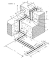
- seal 20 has many portions. There is a first portion 36, which is an end portion, that runs across a flat roof 50, and has a combined length of L 1 + L 2 . First portion 36 is intersected by a second portion 38 that runs perpendicularly away from portion 36 (it need not be perpendicular) a distance L 3 . Second portion 38 ends at a corner, 40, whence another portion 42 runs distance L 2 back toward a wall 44. There is another corner 46, and a portion 48 that runs a distance L 4 along the junction between wall 44 and roof 50.
- Portion 48 ends at a further corner 52 where wall 44 and roof 50 meet another vertical wall 54 (which need not be vertical).
- a further portion 56 runs a distance L 5 up the junction between walls 44 and 54 to reach the intermediate level roof 60, where there is another corner, 58, and a portion 62 that runs a distance L 6 across roof 60 to another wall 64, at which there is a corner 66, which is the opposite hand to corner 46.
- Portion 66 of joint 20 runs a distance L 7 along the junction of roof 60 and wall 64.
- portion 72 ascends wall 64 a distance L 8 to reach roof 70.
- a portion 74 runs across the width L 9 of roof 70, and then a final, end portion 76 runs down rear wall 78 a distance L 10 to its end.
- expansion joint 20 does not necessarily run merely in a straight line. It may have planar portions, such as 36, 38, 42, 62, and 74 that each run in a flat, substantially horizontal plane or planar portions that run in an inclined plane such as the plane of a sloped roof. It may have substantially planar sections, such as 72, that run along or across a substantially or predominantly up-and-down (i.e., vertical) wall. It may have portions such as 48 and 66 in which one leg lies in, and is adhered to, a substantially horizontal plane of an underlying substrate, and one leg to a vertical or inclined plane.
- each leg lies in a different inclined or vertical plane, as in a valley, or at the meeting of two walls or partitions. In each case it is held in place by mechanical adhesion to the underlying substrate with the aid of a resin, such as noted above.
- joint 20 as shown in the layout of Figure 1a has a T-junction, and various corners 40, 46, 52, 58, 66. These corners are factory fabricated by vulcanising. Vulcanised curved joints and multilevel joints can be made in this way. These joints or seams may be made under factory controlled conditions, and provide consistent flexibility. It may tend to eliminate the use of glue, tape or caulking. The entire pre-sized assembly is then packaged and delivered to the installation site. Joint 20 is intended to be what is termed a "flat profile expansion joint", and is to be contrasted with current existing expansion joints such as bellows type joints, prefabricated metal joints, bunched-up membranes, or membranes mounted over a backer rod.
- Joint 20 is substantially flat, or, in the context of folded joints such as 48 or 66, each selvage edge is substantially flat and has a small or very small effective through thickness, either as compared to its own width, or as compared to those previous joint types.
- a flat, or substantially flat, roughly zero profile waterproof joint may tend not unduly to obstruct the flow of water thereacross, and may tend to reduce the tendency of water to pool behind the joint, as if the joint were a dam.
- arrays of apertures 80 are intended to be generic. That is, they could be any of the forms of apertures shown in the various embodiments described in Figures 2a, 3a , 3b, 3c , 3d, 3e, 3f, and 3g herein, or combinations or variations of them.
- Figure 1a is intended to illustrate that arrays of marginal apertures 80 may be formed in both margins, as in portions 38, 72 and 74, or only one margin as in portion 68. They may be used throughout the entire running length of joint 20, or only portions thereof.
- the apertures may be used on a vertical face, whether gravity is acting predominantly along joint 20 as in portion 72, or across joint 20 as in portion 68. Alternatively there may be portions, such as 36 and 42 in which apertures 80 are not employed at all.
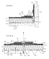
- FIGS 1b and 1c show cross-sections of typical installations. In each case the through-thickness of the various layers has been greatly exaggerated in proportion to the width of the joint for the purpose of conceptual illustration.
- Figure 1b shows a flat roof installation at a joint or gap in a roof B20 , where a concrete structure B22 meets a fabricated steel structure B24 .
- the joint is packed with compressible batt insulation as at B26 , and a vapour barrier or retarder B28 is provided.
- An appropriate substrate may include a layer of compatible insulation material, B30, B32 respectively.
- a base sheet substrate layer B34 overlays the joint.
- Layer B34 may be of any suitable material, of which one example is a modified bitumen membrane layer.
- a slit B36 is made in the base sheet, i.e., layer B34, along the joint.
- an encapsulating layer is applied to base sheet substrate layer B34 on either side of joint B36 to a width comfortably greater than the width of seal 20.
- This encapsulating layer B38 may be a suitable resin such as may be selected from those listed above, and in one example may be an asphalt or bitumen encapsulating layer applied with a mop or other suitable spreading device.
- Joint 20 is then placed atop the layer of resin, and pressed down to seat well. This may be done by hand, or, alternatively, a platen or roller may be used as an aid. One indication of good application may be shown by the visible presence of resin squishing up inside apertures 80.
- an overlay of the encapsulating resin is applied, e.g., by mop, or other suitable means to complete encapsulating layer B38 . The overlay is not mopped onto the gland.
- Left and right hand cap sheets B40 , B42 which may be of the same material as the base sheet, are then placed to cover and adhere to the upper surface of the encapsulating resin.
- An optional layer in the nature of a shield, or mechanical protector B44 may be placed overtop of the margins of sheets B40 and B42 .
- Protector B44 may be secured on one side and substantially free to move on the other, and may overspan gland 28.
- Protector B44 may add, for example, a further layer of puncture resistance.
- Figure 1c shows a flat roof installation at a joint or gap in a structure C20, where a roof structure C22 meets a predominantly vertical wall structure C24.
- the joint is packed with compressible batt insulation as at C26, and a vapour barrier or retarder C28 is provided.
- An appropriate substrate may include a layer of compatible insulation material, C30, applied to roof structure C22.
- a base sheet substrate layer C34 overlays insulation material C30 and terminates at a margin running along and adjacent to the joint.
- Layer C34 may be of any suitable material, of which one example is a modified bitumen membrane layer.
- a base layer such as may be a flashing C32 is mounted to wall structure C24.
- Flashing C32 may be a two ply flashing, which may be a modified bitumen membrane flashing, and which may include a termination bar.
- the first portion of an encapsulating layer is applied to base sheet substrate layer C34 on one side of the joint to a width comfortably greater than the width of seal 20.
- This encapsulating layer B38 may be a suitable resin such as may be selected from those listed above, and in one example may be an asphalt or bitumen encapsulating layer applied with a mop or other suitable spreading device.
- One leg or side, or margin 24 of joint 20 is then placed atop the layer of resin, and pressed down to seat well. This may be done by hand, or, alternatively, a platen or roller may be used as an aid. One indication of good application may be shown by the visible presence of resin oozing, or squishing, or welling up inside apertures 80 such as to fill or partially fill the aperture.
- an overlay of the encapsulating resin is applied, e.g., by mop, or other suitable means to complete encapsulating layer B38. The overlay is not mopped onto the gland.
- a cap sheet B40 which may be of the same material as the base sheet, is then placed to cover and adhere to the upper surface of the encapsulating resin.
- the other leg or margin 26 of joint 20 is placed to lie against, and run along, the inner layer of the two-ply flashing.
- the second, or outer, layer of the two ply flashing overlies the upper edge of margin 26 of joint 20.
- the material forming sheet or slab or member 22 may be made of a synthetic rubber which is both flexible and resilient and which may tend to remain flexible in a wide range of weather conditions.
- a synthetic rubber which is both flexible and resilient and which may tend to remain flexible in a wide range of weather conditions.
- suitable polymeric materials are available for forming sheet or slab or member 22, and several currently available polymeric sheets for use in forming flexible expansion joints may be used.
- Member 22 may have a first or upper surface 114, and an opposite, second, or bottom, surface 116. Member 22 has first and second lengthwise extending opposed side edges 118 and 120. Member 22 has three regions. There may be first and second marginal or edge regions 124, 126, and a third or central, or intermediate region 128 running lengthwise along member 22 between the two edge regions.
- the central region may have a substantially smooth surface on one or, more typically, both faces.
- the adjacent edge regions 124, 126 may have a more roughened surface.
- One way to obtain this rougher surface is to apply a fibrous element, such as fibrous matting, or scrim, in the form of fibrous strips 132, 134, 136, 138 to those edge regions of the first and second surfaces respectively.
- One way to do this is to embed one face of a fibrous matt or strip in the rubber during construction, as at curing, or to bond the fibrous sheet to the elastomeric substrate, or to roughen the rubber surface mechanically as by abrasion.
- the roughened surface, or the dense array of bonded or embedded fibres provides a greater surface area for anchoring in a bonding or resinous material, be it a polymer resin or a more traditional medium such as roofing tar.
- the roughened marginal edge regions, with, for example, embedded fibrous material may be referred to as, and may define selvage edges 24, 26.
- Selvage edges 24, 26 are of equal width. While this is typically so, if need not necessarily be so, and the edges may be of unequal widths, particularly if one edge is to lie horizontally, and one edge is to bend upward and bear against a wall or wall flashing.
- Surface 114 has rough strips 132 and 134 and surface 116 has rough strips 136 and 138.
- Rough strips 132 and 136 may be are arranged parallel to rough strips 134 and 138.
- Rough strips 132, 136 lie adjacent to side edge 118, while rough strips 134 and 138 lie adjacent to side edge 120.
- Rough strips 132, 134 and 136, 138 form areas of surface 114 and 116, respectively, that have been treated to augment or enhance the surface area to which an adhesive resin may bond.
- Quite thin regions along the very edges of member 22 laterally outboard of roughened strips 132, 134, 136, and 138 respectively may be smooth, as at 133, 135, 137, and 139.
- the rough strips may extend fully to the edge of the member 22.
- the width of these thin regions is indicated as D 135 , and, as noted, may be as small as zero.
- the third, or central region or portion 128 defines central gland 28 of member 22 and may have bare or smooth portions 140 and 142 on surfaces 114 and 116 respectively. These portions are positioned, in this instance generally centrally, between strips 22, 24 and 26, 28, respectively.
- the selvage edges may be relatively stiffer than the gland in tension and shear. That is, the gland may be "stretchier", or of greater elasticity than the selvage edges. This may be due to a different, i.e., slightly greater, thickness than the gland, and due to the embedded strips of rougher material, those strips tending to be more inelastic than the underlying (typically rubber) matrix.
- the respective widths W 140 and W 142 of smooth portions 140, 142 need not be equal.
- the width of the lower smooth region may be narrower than the upper smooth region.
- widths W 140 and W 142 may be the same.
- the mean gland width, D 128 may be taken as the average of widths W 140 and W 142 .
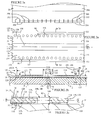
- a series, or array, of apertures 144, 146 is formed in each of the selvage edges, namely regions 124, and 126. These apertures are positioned along member 22 adjacent, edges 118 and 120, respectively, running generally parallel thereto. As seen in Figure 2b , each aperture passes through sheet 22 and the fibrous matting of the roughened strips, 132, 134, 136 and 138, as may be. As seen in the enlarged detail of Figure 2c , apertures 144, 146 may each have a right angled edge portion 148 where the bore of the aperture intersects or meets surfaces 114 and 116.
- a series of apertures may tend to reduce the creep of the finished and installed expansion joint. This may be considered a surprising or counter intuitive view. One might expect that providing apertures along the rough strips would decrease the surface area of contact between the joint and the bonded substrate, S , of Figure 2b to which the joint is bonded. However, the apertures may tend to decrease the amount of creep. It is believed that the right angled edges 38 of the apertures may act in a conceptually similar manner to the treads of a car tire, increasing the amount of "traction" between the sheet and the bonding agent, be it tar or some other resin applied to bond the expansion joint to the substrate. Ridges or creases in the sheet may act is a similar way, however, forming a resilient sheet with ridges and the like is quite awkward and expensive compared to simply punching a series of apertures through the sheet.
- expansion joint 20 it overlies an underlying structure, such as mating roof panels, or substrates, S 1 and S 2 , that meet along a crack or joint 'C', and that are susceptible to a measure of relative movement at that crack or joint 'C', such that a flexible expansion joint member of some kind is required.
- the interface between the substantially planar face of member 22 and the underlying substrate portions, S 1 and S 2 is substantially planar, as symbolized by interface plane, P.
- the bonding agent will form a relatively thin layer between member 22 and substrate S.
- member 22 is shown slightly away from the substrate members, by a small gap. This is intended to be representative of the space occupied by the resin. The size of the gap and the vertical relative thickness of the parts is exaggerated for the purposes of illustration. That bonding layer may tend to be cycled in shear during contraction, expansion or shifting of the adjacent underlying roof panels.
- the bonding agent apertures permit the sealing resin to flow and accumulate in the out-of-plane direction away from plane P.
- the bonding agent may then gain a mechanical grip on the non-planar edge or face of the aperture that stands away from, e.g., typically some distance perpendicular to, interface plane, P.
- the aperture edges may tend to act somewhat analogous to fillet welds in shear.
- Another feature of an aperture that penetrates through the thickness of the material is that it permits relatively easy visual inspection of the presence of the bonding resin at the bonding interface, and in the apertures.
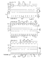
- an expansion joint 200 has an array of apertures 202 each of which has the form of an open-ended slot that extends inboard from the respective edge 204.
- the inboard end of the slot, or the head of the slot may have a bulbous enlargement as at 206.
- joint 200 may be taken to be symmetrical, another similar array of slots may be understood to be formed in the opposite selvage edge.
- an expansion joint 220 employs arrays of apertures 222 that are not circular, but have the form of a polygon, in this instance a triangle.
- the triangles of the array are alternating as at 224, 226, such as to leave alternatingly angled intermediate strut portions 228, 230 that may tend to yield a wedge-like resistance to shear force application in the plane of joint 228.
- an expansion joint 240 has a series of ovate slots 242 having closed peripheries (as compared to slots 202 that each have an open ended periphery) Slots 242 have a long axis that is substantially perpendicular to the running direction or x-axis, of joint 240 more generally. Although only an half view is shown, the other half may be taken to be symmetrical. The pitch between the slot centers in the x-direction may be greater than 3 ⁇ 4 of the lateral length L 242 of the slots, and may tend to be in the range of 3 ⁇ 4 to 3/2 times the length L 242 .
- an expansion joint 260 has a series of slots 262, not unlike slots 242, except that slots 262 include left hand and right hand angled slots 264, 266 that have a mutually wedging orientation, and that leave alternating wedge-like tab areas 268, 270.
- joint 260 may be symmetrical, in which case matching apertures are also formed in the opposite selvage edge.
- the angles of the slots relative to the x-axis are indicated as alpha and beta. Although it is convenient that these angles be the same, they need not be. The angles may tend to be greater than 45 degrees and may lie in the range of 60 to 75 degrees.
- the pitch spacing of apertures 262 is similar to that of apertures 242.
- an expansion joint 280 has an array of apertures 282, in which the apertures have a generally curved shape. In this instance the curve is gently S-shaped.
- the pitch spacing of apertures 282 is similar to that of apertures 242.
- apertures 302 in which the array has an alternating inboard and outboard stagger, the inboard apertures being indicated as 304, and the outboard apertures as 306. While apertures 304 and 306 are round circular apertures, any of the oval, triangular of curved apertures of the other embodiments of Figures 3a , 3b, 3c , 3d, and 3e could also have an inboard-outboard alternating stagger.
- the pitch spacing of apertures 302 is similar to that of apertures 242.
- expansion joint 320 has an array of marginal fingers 322 and corresponding apertures 324 defined between those fingers, the edges of fingers 322 and corresponding wedge-shaped apertures 324 being alternately angled at angles phi and theta. These angles are comparatively sharp, and may be greater than 60 degrees relative to the running direction of the joint. Expressed in the context of the lateral direction, the tangent portion of the edge, or the average angle if the edge is not straight, may be in the range of perhaps 10 - 30 degrees. Again, while these angles may be equal, and repeating, they need not necessarily be so. The resultant feathered edge may be termed undulating, serpentine, saw toothed, deviating, and so on.
- a deviating edge as show will necessary have a longer edge length than the straight line running distance of the joint. While apertures 324 are of the same size, they could also have an inboard-outboard alternating stagger. A serpentine or deviating edge may also be used in combination with closed periphery apertures such as shown in others of the embodiments presented herein.
- the various apertures are located in the laterally outermost third or quarter of the respective selvage edges.
- the lateral extent of each aperture is less than 1/3 of the lateral extent of the selvage edge, and may be in the range of 1/8 to 1 ⁇ 4 of that width.
- the length of the aperture may be in the range of 3 ⁇ 4" to 2 1 ⁇ 2", depending on the size of the joint.
- the major axis of the aperture, or major portions of the edge of the aperture tend not to be parallel to the x-direction, or to the nominal direction of edges 118, 120. Rather they have a component that is perpendicular, or predominantly away from those edges, even if obliquely so.
- the resistance of the selvage edge to creep may to some extent then be a function of the arc length of the sum of the perimeters of the apertures. That is, the resistance to creep may be enhanced where the effective length of the selvage edge is greater than the nominal straightline length of that edge.
- One proxy for the effective length of that shear edge is the sum of the length of the edge itself plus the lengths of the apertures, divided by the nominal straightline length of the edge, expressed as a ratio or as a percent. In all of the illustrated embodiments that ratio is greater than 100 %. It may be greater than 150 %, and may be in the range of 180 - 250 % of the corresponding straight line running length.
Landscapes
- Engineering & Computer Science (AREA)
- Architecture (AREA)
- Civil Engineering (AREA)
- Structural Engineering (AREA)
- Physics & Mathematics (AREA)
- Electromagnetism (AREA)
- Building Environments (AREA)
- Joints Allowing Movement (AREA)
Abstract

Description
- This application claims priority from Canadian Patent Application
CA 2,668,073 filed June 2, 2009 by the Applicant Krzystof Zielonka, the subject matter of the specification, drawings, and claims thereof being incorporated herein by reference. - The invention relates generally to rubber or polymeric waterproof expansion joints.
- Rubber expansion joints are often used in construction to help water proof roofs, slabs, and walls, thereby to protect the structure from effluent damage, which may typically be water damage. Traditionally, these expansion joints have included an elongated flat sheet of rubber, vinyl or some other flexible, resilient polymeric material. These expansion joints are usually laid over a joint between two walls or two sheets of waterproofing tiles or fabric. Expansion joints are typically secured to the surface of the joint by adhesive such as tar or the like.
- Rubber expansion joints may be present some challenges or disadvantages. For example, on hot summer days, the tar or adhesive used to bond the joint to the underlying substrate and to hold the joint in place may soften or weaken. This may result in the joint to becoming dislodged and slipping or creeping or migrating away from its desired position. That is, when the bond holding the joint softens, the joint may tend to move, or creep, across the surface of the substrate to which the joint is bonded. This creeping of the joint may result in the failure of the waterproof joint. So far, the only way to ensure that the joint is well adhered is to maximize the surface area of contact between the joint and the adhesive used to bond the joint. This can be done by increasing the surface area dimensions of the sheet, i.e. providing a wider sheet, and or by increasing the surface area of the sheet by roughing up the surface by means of bonding fibrous matting to the surface of the sheet. While these approaches are effective in increasing the adhesion of the joint to the adhesive, increasing the dimensions of the sheet increases its cost; and fibrous matting bonded to the sheets often dislodge from the sheet surface due to poor adhesion of the fibrous matt to the sheet.
- In an aspect of the invention, there is a substantially flat expansion joint. The expansion joint has first and second elastomer based selvage edges and an elastomeric gland located between the selvage edges. The gland is for deployment in a lengthwise direction along an underlying structural interface. At least a portion of the first selvage edge has a plurality of apertures formed therethrough.
- In a feature of that aspect of the invention the first selvage edge has a total edge length that includes the edge lengths of the apertures. A ratio of the total edge length per unit of running length of the portion in the lengthwise direction is greater than 125%. In another feature the ratio exceeds 200 %. In a further feature, the apertures include an array of slots pitched along the running direction, the slots have a major dimension, and the major dimension is predominantly transverse to the lengthwise direction. In still another feature the apertures are formed in an array of apertures having edges oriented obliquely to the lengthwise direction. In another feature apertures on successive pitches are oriented on alternating left hand and right hand oblique angles. In a yet further feature the apertures have a closed periphery. In an alternate feature the apertures have an at least partially open periphery. In still yet another feature the first selvage edge includes at least a first scrim, and the apertures are formed at least in part through the scrim. In again another feature the first and second selvage edges each have a first surface for placement against structure to which the expansion joint is to be applied, and a second face for orientation facing away from the structure, and both the first and second faces include a scrim.
- In another feature the selvage edges have a transverse width, W. The selvage edges have a most transversely outboard third. The apertures have an extent, L, transverse to the lengthwise direction. The apertures are located in the most transversely outboard third. The extent, L, has a magnitude that is in the range of one eighth to one third of W. In still yet a further feature the first and second selvage edges each have an array of the apertures formed therein, the apertures are circular, closed periphery apertures formed in an outermost one third of each the selvage edge respectively, and the apertures have a diameter to pitch spacing ratio in the range of 1/8 to 3/4.
- In a still yet further feature the joint includes first and second portions meeting at a corner, the first and second portions have respective rubber-based matrices; and the first and second portions are vulcanized together. In another feature the expansion joint has first and second portions, each of the first and second portions having respective first and second selvage edges; the first portion has arrays of the apertures formed in both of the selvage edges, and the second portion has at least one selvage edge that is free of the apertures.
- In another aspect of the invention, there is a method of installing a flat expansion joint on a structure. The structure has first and second portions, and an interface between the first and second portions. The expansion joint has a rubber based matrix. The expansion joint has a lengthwise running gland located between a pair of first and second selvage edges that run along the gland and extend laterally away therefrom. Those selvage edges have apertures formed therethrough. The method includes treating a surface portion of each of the first and second portions of the structure with a resin; placing the first selvage edge in the resin on the first portion of the structure; placing the second selvage edge in the resin on the second portion of the structure; smoothing the expansion joint in place; observing occupation of the apertures with the resin as the expansion joint is smoothed in place; and applying a further amount of resin to cover the selvage edges while leaving the gland uncovered. In a feature of that aspect of the invention, the method further includes applying a mechanical protector over the gland. In another feature the expansion joint has a fibrous scrim mounted to each the selvage edge, and the method includes saturating the fibrous scrim in the resin.
- In another aspect of the invention there is an expansion joint. It has an elongated flat sheet of flexible and resilient polymeric material having a width, opposite upper and lower surfaces, and opposite first and second edges. One of the opposite surfaces is a first surface, and has a fibrous section including a section of the sheet having a plurality of fibers secured to the surface. The fibrous section extends along the first surface adjacent one of the edges. A series of apertures passes through the sheet and is positioned on the fibrous section, with the apertures being positioned adjacent one of the side edges.
- In a feature of that aspect of the invention, each of the upper and lower surfaces have the fibrous section. In another feature each of the fibrous sections comprises a parallel pair of first and second fibrous matts secured to the surface. The fibrous matts are separated by an elongated strip of bare surface. The first and second fibrous matts are located adjacent to the first and second edges of the sheet, respectively, with the apertures forming a parallel pair of first and second rows of apertures positioned adjacent the first and second edges.
- In another aspect of the invention there is an expansion joint. It has an elongated flat sheet of flexible and resilient polymeric material having a width, a length, opposite upper and lower surfaces and opposite first and second edges. The sheet has a parallel pair of fibrous first and second matts secured to each of the opposite surfaces along the length of the sheet. The parallel fibrous matts on each surface are separated by an elongated strip of bare surface. The first and second fibrous matts are located adjacent the first and second edges of the sheet, respectively. Parallel rows of first and second rows of apertures are positioned adjacent to the first and second edges, respectively. Each of the row of apertures passing through the sheet and the fibrous matts. In a feature of that aspect of the invention, each of the apertures have substantially right angled edges. In another feature the apertures are substantially circular.
- In a further aspect of the invention there is an expansion joint. It has an elongated flat sheet of flexible and resilient polymeric material having a width, a length, opposite upper and lower surfaces and opposite first and second edges. The sheet has a parallel pair of elongated first and second rough strips formed on each of the opposite surfaces along the length of the sheet. The rough strips on each surface are separated by an elongated strip of bare surface. The first and second rough strips are located adjacent the first and second edges of the sheet, respectively. Parallel first and second series of apertures are positioned adjacent to the first and second edges, respectively. Each aperture passes through the sheet and the rough strips.
- In a feature of that aspect of the invention, a portion of each of the rough strips includes fibrous material secured to the sheet. In another feature the rough strips each include a fibrous matt secured to the sheet. In another feature each of the apertures has a substantially right angled edge. In another feature the apertures are substantially circular. In another feature the apertures are substantially polygonal. In a further feature the apertures are substantially triangular. In an alternate feature the apertures are curved. In a further feature the apertures are substantially S-shaped. In another feature the apertures are slots. In another feature the slots have closed peripheries. In another feature the slots are on alternating oblique angles relative to the longitudinal direction to give a wedge arrangement. In an alternate feature, the slots have a closed periphery. In a further feature the slots have a closed and, an open end, and walls that converge from said open end to said closed end.
- These and other aspects and features of the invention may be understood with reference to the description that follows, and with the illustrations of a number of examples.
-
-
Figure 1a is an isometric, not-to-scale view of a three-dimensional expansion joint installation such as may incorporate aspects of the present invention; -
Figure 1b is a cross-sectional view of a horizontal portion of an installation such as that ofFigure 1a , in which the thickness of the expansion joint is exaggerated; -
Figure 1c is a cross-sectional view of an application of a roof-to-wall expansion joint portion of an installation such as that ofFigure 1a , in which the thickness of the expansion joint has been exaggerated; -
Figure 2a is a plan view of an embodiment of an expansion joint according to an aspect of the present invention; -
Figure 2b is a cross sectional view of the expansion joint ofFigure 2a taken along line section '2b - 2b' ofFigure 2a ; -
Figure 2c is an expanded view of a portion ofFigure 2b showing details of the edge of an aperture; -
Figure 3a is a plan view of an alternate embodiment of expansion joint to that ofFigure 2a , in which the expansion joint has a series of open ended slots; -
Figure 3b is a plan view of a further alternate embodiment of expansion joint to that ofFigure 2a , in which the expansion joint has a series of non-circular slots; -
Figure 3c is a plan view of a further alternate embodiment of expansion joint to that ofFigure 2a , in which the expansion joint has a series of closed parallel slots; -
Figure 3d is a plan view of a further alternate embodiment of expansion joint to that ofFigure 2a , in which the expansion joint has a series of angled slots; -
Figure 3e is a plan view of a further alternate embodiment of expansion joint to that ofFigure 2a , in which the expansion joint has a series of arcuate slots; -
Figure 3f is a plan view of a further alternate embodiment of expansion joint to that ofFigure 2a , in which the expansion joint has a staggered series of slots; and -
Figure 3g is a plan view of a further alternate embodiment of expansion joint to that ofFigure 2a , in which the expansion joint has a staggered series of slots having angled edges yielding a serpentine or sawtooth edge. - In the drawings like characters of reference indicate corresponding parts in the different figures.
- The description that follows, and the embodiments described therein, are provided by way of illustration of examples of particular embodiments of the principles, aspects or features of the present invention. These examples are provided for the purposes of explanation, and not of limitation, of those principles and of the invention. In the description, like parts are marked throughout the specification and the drawings with the same respective reference numerals. The drawings are generally to scale in plan view. However, in view of the aspect ratios of thickness to width, the thickness has been exaggerated or enlarged in some views for the purposes of clarity of illustration.
- The subject matter herein is intended to include all combinations and permutations of the various individual features shown and described. To the extent that any such feature was subject to a claim in Canadian Patent Application
CA 2,668,073 from which this case claims priority, and which is incorporated herein by reference, it will be understood that the subject matter herein includes the combinations of those claimed features had they been written in multiply dependent form rather than in singly dependent form. Furthermore, the subject matter includes the subject matter of all of the independent claims filed inCA 2,668,073 and all of the dependent claims filed in that case, including all combinations and permutations of those independent claims and the dependent claims therein that could have been made. The Applicant does not disclaim, and reserves the right to claim, any and all such permutations and combinations of claimed features, whether previously combined or separate, as if claims for those combinations had been submitted herewith on the date of filing, whether or not such combinations and permutations were explicitly claimed either separately or in combination. The subject matter is not limited to the particular words used herein, but includes synonyms and alternate forms of expression having substantially the same meaning. The subject matter is not limited to those features described in the written text, but includes that subject matter that can fairly be inferred or otherwise understood by a person of ordinary skill in the art on the basis of the illustrations, whether supported in the written text of the application or not. The Applicant reserves the right to add such written text as may fairly comport with the understanding of a person of ordinary skill in the art of the features shown in the illustrations. - The terminology used in this specification is thought to be consistent with the customary and ordinary meanings of those terms as they would be understood by a person of ordinary skill in the art in North America. Following from decision of the US Court of Appeals for the Federal Circuit in Phillips v. A WH Corp., the Applicant expressly excludes all interpretations that are inconsistent with this specification, and, in particular, to forestall overly broad interpretation under the rule of broadest reasonable interpretation, excludes all interpretations other than those interpretations that are consistent with actual usage in the industry as understood by persons of ordinary skill in the art, or that are expressly supported by this specification. Each of the claims, whether in the form of a sub-combination or combination, is to be interpreted as an whole, and is not to be interpreted as having a first part and a second or "characterizing" part. It is to be understood that the features of any dependent claim herein may be amended or copied to depend from a different independent claim, or string of claims. It is also to be understood that although a claim may include multiple alternate parts, any one or group of those parts may be made the subject matter of another dependent or independent claim.
- In terms of general orientation and directional nomenclature, for expansion joints as described herein a Cartesian frame of reference may be employed in which the longitudinal direction is defined as being coincident with the running direction of the joint, and may be considered to be the x-axis or x-direction. Similarly the width of the joint perpendicular to the running direction may be considered the y-direction. The through thickness may be considered the z-direction. In the context of the joint as an whole, the term lateral, or laterally outboard, or transverse, or transversely outboard refer to a distance or orientation relative to the longitudinal centerline of the joint.
- Referring to
Figures 1a ,1b ,1c ,2a, 2b and 2c , an expansion joint is shown generally asitem 20. It includes a flat elongated sheet or slab ormember 22 of rubber material that may be considered conceptually to be a membrane in which the through thickness is small as compared to the overall width, and, typically, the width is small or very small as compared to the length. That is, the width, D20 , may be of an order of magnitude greater than the thickness, t20 . For example, t20 , may be in the range of perhaps 3/32" to 5/32" (1.8 mm, 2mm, 2.2 mm or 3 mm, +/-) thick, whereas the overall width D20 of may be in the range of, for example, about 7" to 22" (175 mm to 540 mm), or perhaps more, with mid-range sizes of perhaps about 10" or 10-½" (270 mm, +/-), about 13 - 13 ½ (340 mm, +/-), or about 15" or 16" (400 mm, +/-). Thus the aspect ratio of the material in terms of width to thickness may be of the order of about 80:1 or 100:1 to about 300:1 or 400:1, depending on the installation. The length may be considered potentially to be substantially infinite as compared to the width since, in general, the joint is supplied in a roll that is paid out linearly along the discontinuity to be sealed, which may be 20, 30, 50, or 100 or more feet long. - In terms of a general overview,
expansion joint 20 has the form of a strip having a pair of first and second lengthwise running margins, or portions, called selvage edges 24, 26 and a central portion called agland 28. The selvage edges include an embedded stiffening element, termed a scrim and indicated as 34.Scrim 34 may also be fibrous to promote better adhesion on installation, as described below. The scrim may be a partially exposed surface layer, or it may be fully embedded within the matrix of the expansion joint margins. - In one type of expansion joint, 20, the waterproofing material of the expansion joint may typically be a continuous material strip compounded from a rubber based elastomer. During the manufacturing process a scrim, i.e., a reinforcement, which may for example be in the form of a polyester fleece, is embedded in the gelling elastomer matrix in the selvage edge on both sides of the joint. In some instances, as with a mop applied tar joint, the reinforcing is at least partially external, leaving a roughened or fibrous surface to which the binder, or resin, be it epoxy or tar, or some other material, may be applied. In each case, the reinforcing material does not extend to the expanding or stretching section, namely
gland 28. Another type or embodiment of expansion joint employs a scrim that is embedded as a middle layer in a flame proof rubber matrix, such as may be installed using a flame-heated resin. In a third type or embodiment of expansion joint the scrim is again fully embedded in the rubber matrix, and may be for use with an epoxy resin in installations as a swimming pool or other liquid-containing tank seal, and such as may include potable water containing structures. In each of the second and third instances, the upper and lower surfaces or the selvage edges may be roughened, or moulded to have a non-smooth surface, such as may, for example, have the appearance of being knurled. - The elastomeric base material may tend to be rubber, and that rubber may tend to be a rubber that is resistant to one or several of UV light, ozone, alkalis, acids, saline solutions, alcohols and ketones. Depending on the circumstances, the joint may be secured in place with a resin, such as may be chosen from the set of resions that includes roofing tars and asphalts; asphaltic saturants; built-up-roof materials (BUR); coal tar pitch (CTP); modified bitumen (SBS / APP); hot rubberized asphalt (HRA); cold advhesives (CAA); spray polyurethan foam (SPF); liquid applied membranes (LAM); Epoxy Resin (ER); EPDM Tie-in or PVC/TPO tie-in. One type of rubber based material typically has an initial Durometer A hardness of approximately 45 +/- 5 according to ASTM D2240. The gland will have an elongation to breaking under ASTN D412 of greater than 500 %, and a tear resistance under ASTM D624 of at least 220 1bf/in, (approx. 40 N/mm).
- Installation may include the use of a resin such as one of the resins noted above. For example, an asphalt or bitumen tar, may be mopped onto the substrate. The substrate may be some type of base ply roofing layer. The expansion joint is then laid over the joint to be sealed, and then further resin is applied to cover at least the selvage edges. Further materials, such as pea gravel in the case of a built-up roof, may overlay the selvage edges. A protective mechanical layer may in turn bridge across the gland and overlap the inner portions of the selvage edges to provide mechanical protection to the gland, without being attached to, or interfering with the operation of, the gland.
- Although expansion joints of this nature may typically be applied across a substantially flat joint, i.e., where, at least initially, the substrates on either side of the joint are substantially co-planar, this need not necessarily be so. For example, an expansion joint may be applied between a substantially horizontal planar portion and a substantially vertical planer portion, as where a building addition of one height meets a taller existing structure, or where the joint lies closely adjacent an upstanding feature, such as a skylight surround. In these cases one selvage edge may lie in the plane of the roof, and adhere to an underlying roof substrate, while the other selvage edge may bear against, and by the use of a suitable resin may adhere to, a flashing or other like element.
- The geometry of the expansion joint, and its orientation may vary along its length. Expansion joints such as those described herein need not merely run in a single straight line. In
Figure 1a , which is not to scale,seal 20 has many portions. There is afirst portion 36, which is an end portion, that runs across a flat roof 50, and has a combined length of L1 + L2 .First portion 36 is intersected by asecond portion 38 that runs perpendicularly away from portion 36 (it need not be perpendicular) a distance L3 .Second portion 38 ends at a corner, 40, whence anotherportion 42 runs distance L2 back toward awall 44. There is anothercorner 46, and aportion 48 that runs a distance L4 along the junction betweenwall 44 and roof 50.Portion 48 ends at afurther corner 52 wherewall 44 and roof 50 meet another vertical wall 54 (which need not be vertical). Afurther portion 56 runs a distance L5 up the junction betweenwalls 44 and 54 to reach theintermediate level roof 60, where there is another corner, 58, and aportion 62 that runs a distance L6 acrossroof 60 to anotherwall 64, at which there is acorner 66, which is the opposite hand to corner 46.Portion 66 of joint 20 runs a distance L7 along the junction ofroof 60 andwall 64. At anothercorner 66portion 72 ascends wall 64 a distance L8 to reachroof 70. Aportion 74 runs across the width L9 ofroof 70, and then a final,end portion 76 runs down rear wall 78 a distance L10 to its end. - As can be seen in this example,
expansion joint 20 does not necessarily run merely in a straight line. It may have planar portions, such as 36, 38, 42, 62, and 74 that each run in a flat, substantially horizontal plane or planar portions that run in an inclined plane such as the plane of a sloped roof. It may have substantially planar sections, such as 72, that run along or across a substantially or predominantly up-and-down (i.e., vertical) wall. It may have portions such as 48 and 66 in which one leg lies in, and is adhered to, a substantially horizontal plane of an underlying substrate, and one leg to a vertical or inclined plane. It may have portions such as 56 in which each leg lies in a different inclined or vertical plane, as in a valley, or at the meeting of two walls or partitions. In each case it is held in place by mechanical adhesion to the underlying substrate with the aid of a resin, such as noted above. - As may be noted, joint 20 as shown in the layout of
Figure 1a has a T-junction, andvarious corners - In looking at the various portions of joint 20, we see, for example that various portions have arrays of
apertures 80 formed in their outboard marginal edge regions. These arrays ofapertures 80 are intended to be generic. That is, they could be any of the forms of apertures shown in the various embodiments described inFigures 2a, 3a ,3b, 3c, 3d, 3e, 3f, and 3g herein, or combinations or variations of them.Figure 1a is intended to illustrate that arrays ofmarginal apertures 80 may be formed in both margins, as inportions portion 68. They may be used throughout the entire running length of joint 20, or only portions thereof. The apertures may be used on a vertical face, whether gravity is acting predominantly along joint 20 as inportion 72, or across joint 20 as inportion 68. Alternatively there may be portions, such as 36 and 42 in which apertures 80 are not employed at all. -
Figures 1b and 1c show cross-sections of typical installations. In each case the through-thickness of the various layers has been greatly exaggerated in proportion to the width of the joint for the purpose of conceptual illustration. -
Figure 1b shows a flat roof installation at a joint or gap in a roof B20, where a concrete structure B22 meets a fabricated steel structure B24. The joint is packed with compressible batt insulation as at B26, and a vapour barrier or retarder B28 is provided. An appropriate substrate may include a layer of compatible insulation material, B30, B32 respectively. A base sheet substrate layer B34 overlays the joint. Layer B34 may be of any suitable material, of which one example is a modified bitumen membrane layer. A slit B36 is made in the base sheet, i.e., layer B34, along the joint. The lower portion of an encapsulating layer is applied to base sheet substrate layer B34 on either side of joint B36 to a width comfortably greater than the width ofseal 20. This encapsulating layer B38 may be a suitable resin such as may be selected from those listed above, and in one example may be an asphalt or bitumen encapsulating layer applied with a mop or other suitable spreading device. - Joint 20 is then placed atop the layer of resin, and pressed down to seat well. This may be done by hand, or, alternatively, a platen or roller may be used as an aid. One indication of good application may be shown by the visible presence of resin squishing up inside
apertures 80. Once joint 20 has been applied and smoothed down, an overlay of the encapsulating resin is applied, e.g., by mop, or other suitable means to complete encapsulating layer B38. The overlay is not mopped onto the gland. Left and right hand cap sheets B40, B42, which may be of the same material as the base sheet, are then placed to cover and adhere to the upper surface of the encapsulating resin. An optional layer in the nature of a shield, or mechanical protector B44 may be placed overtop of the margins of sheets B40 and B42. Protector B44 may be secured on one side and substantially free to move on the other, and may overspangland 28. Protector B44 may add, for example, a further layer of puncture resistance. -
Figure 1c shows a flat roof installation at a joint or gap in a structure C20, where a roof structure C22 meets a predominantly vertical wall structure C24. The joint is packed with compressible batt insulation as at C26, and a vapour barrier or retarder C28 is provided. An appropriate substrate may include a layer of compatible insulation material, C30, applied to roof structure C22. A base sheet substrate layer C34 overlays insulation material C30 and terminates at a margin running along and adjacent to the joint. Layer C34 may be of any suitable material, of which one example is a modified bitumen membrane layer. On the other side of the gap, or joint, a base layer, such as may be a flashing C32 is mounted to wall structure C24. Flashing C32 may be a two ply flashing, which may be a modified bitumen membrane flashing, and which may include a termination bar. The first portion of an encapsulating layer is applied to base sheet substrate layer C34 on one side of the joint to a width comfortably greater than the width ofseal 20. This encapsulating layer B38 may be a suitable resin such as may be selected from those listed above, and in one example may be an asphalt or bitumen encapsulating layer applied with a mop or other suitable spreading device. - One leg or side, or
margin 24 of joint 20 is then placed atop the layer of resin, and pressed down to seat well. This may be done by hand, or, alternatively, a platen or roller may be used as an aid. One indication of good application may be shown by the visible presence of resin oozing, or squishing, or welling up insideapertures 80 such as to fill or partially fill the aperture. Once joint 20 has been applied and smoothed down, an overlay of the encapsulating resin is applied, e.g., by mop, or other suitable means to complete encapsulating layer B38. The overlay is not mopped onto the gland. A cap sheet B40, which may be of the same material as the base sheet, is then placed to cover and adhere to the upper surface of the encapsulating resin. The other leg ormargin 26 of joint 20 is placed to lie against, and run along, the inner layer of the two-ply flashing. The second, or outer, layer of the two ply flashing overlies the upper edge ofmargin 26 of joint 20. By observation,gland 28 has been bent out-of-plane to permit the other selvage edge to seat against vertical wall structure C24. - Considering now
figures 2a, 2b and 2c , the material forming sheet or slab ormember 22 may be made of a synthetic rubber which is both flexible and resilient and which may tend to remain flexible in a wide range of weather conditions. Several suitable polymeric materials are available for forming sheet or slab ormember 22, and several currently available polymeric sheets for use in forming flexible expansion joints may be used. -
Member 22 may have a first orupper surface 114, and an opposite, second, or bottom,surface 116.Member 22 has first and second lengthwise extending opposed side edges 118 and 120.Member 22 has three regions. There may be first and second marginal oredge regions intermediate region 128 running lengthwise alongmember 22 between the two edge regions. The central region may have a substantially smooth surface on one or, more typically, both faces. Theadjacent edge regions fibrous strips selvage edges - Selvage edges 24, 26 are of equal width. While this is typically so, if need not necessarily be so, and the edges may be of unequal widths, particularly if one edge is to lie horizontally, and one edge is to bend upward and bear against a wall or wall flashing.
-
Surface 114 hasrough strips surface 116 hasrough strips Rough strips rough strips Rough strips side edge 118, whilerough strips side edge 120.Rough strips surface member 22 laterally outboard of roughenedstrips member 22. The width of these thin regions is indicated as D135 , and, as noted, may be as small as zero. - The third, or central region or
portion 128 definescentral gland 28 ofmember 22 and may have bare orsmooth portions surfaces strips smooth portions - A series, or array, of
apertures regions member 22 adjacent, edges 118 and 120, respectively, running generally parallel thereto. As seen inFigure 2b , each aperture passes throughsheet 22 and the fibrous matting of the roughened strips, 132, 134, 136 and 138, as may be. As seen in the enlarged detail ofFigure 2c ,apertures angled edge portion 148 where the bore of the aperture intersects or meetssurfaces - A series of apertures, such as 144, 146, may tend to reduce the creep of the finished and installed expansion joint. This may be considered a surprising or counter intuitive view. One might expect that providing apertures along the rough strips would decrease the surface area of contact between the joint and the bonded substrate, S, of
Figure 2b to which the joint is bonded. However, the apertures may tend to decrease the amount of creep. It is believed that the right angled edges 38 of the apertures may act in a conceptually similar manner to the treads of a car tire, increasing the amount of "traction" between the sheet and the bonding agent, be it tar or some other resin applied to bond the expansion joint to the substrate. Ridges or creases in the sheet may act is a similar way, however, forming a resilient sheet with ridges and the like is quite awkward and expensive compared to simply punching a series of apertures through the sheet. - That is to say, the premise of
expansion joint 20 is that it overlies an underlying structure, such as mating roof panels, or substrates, S1 and S2 , that meet along a crack or joint 'C', and that are susceptible to a measure of relative movement at that crack or joint 'C', such that a flexible expansion joint member of some kind is required. The interface between the substantially planar face ofmember 22 and the underlying substrate portions, S1 and S2 , is substantially planar, as symbolized by interface plane, P. Even when applied generously, the bonding agent will form a relatively thin layer betweenmember 22 and substrate S. In the illustrations ofFigures 2c member 22 is shown slightly away from the substrate members, by a small gap. This is intended to be representative of the space occupied by the resin. The size of the gap and the vertical relative thickness of the parts is exaggerated for the purposes of illustration. That bonding layer may tend to be cycled in shear during contraction, expansion or shifting of the adjacent underlying roof panels. - The bonding agent apertures permit the sealing resin to flow and accumulate in the out-of-plane direction away from plane P. The bonding agent may then gain a mechanical grip on the non-planar edge or face of the aperture that stands away from, e.g., typically some distance perpendicular to, interface plane, P. Furthermore, to the extent that the resin forms a semi-solid plug in the aperture, the aperture edges may tend to act somewhat analogous to fillet welds in shear. Another feature of an aperture that penetrates through the thickness of the material is that it permits relatively easy visual inspection of the presence of the bonding resin at the bonding interface, and in the apertures.
- In the embodiment of
Figures 2a, 2b and 2c , the apertures have closed perimeters, being circular, straight through bores penetrating through the selvage margins. The Apertures need not be circular, and they need not necessarily have closed peripheries. For example, in the embodiment ofFigure 3a , anexpansion joint 200 has an array ofapertures 202 each of which has the form of an open-ended slot that extends inboard from therespective edge 204. The inboard end of the slot, or the head of the slot, may have a bulbous enlargement as at 206. To the extent that joint 200 may be taken to be symmetrical, another similar array of slots may be understood to be formed in the opposite selvage edge. - In the embodiment of
Figure 3b anexpansion joint 220 employs arrays ofapertures 222 that are not circular, but have the form of a polygon, in this instance a triangle. The triangles of the array are alternating as at 224, 226, such as to leave alternatingly angledintermediate strut portions - In the embodiment of
Figure 3c , an expansion joint 240 has a series ofovate slots 242 having closed peripheries (as compared toslots 202 that each have an open ended periphery)Slots 242 have a long axis that is substantially perpendicular to the running direction or x-axis, of joint 240 more generally. Although only an half view is shown, the other half may be taken to be symmetrical. The pitch between the slot centers in the x-direction may be greater than ¾ of the lateral length L242 of the slots, and may tend to be in the range of ¾ to 3/2 times the length L242. - In the embodiment of
Figure 3d , anexpansion joint 260 has a series ofslots 262, not unlikeslots 242, except thatslots 262 include left hand and right hand angledslots like tab areas apertures 262 is similar to that ofapertures 242. - In the embodiment of
Figure 3e , anexpansion joint 280 has an array ofapertures 282, in which the apertures have a generally curved shape. In this instance the curve is gently S-shaped. The pitch spacing ofapertures 282 is similar to that ofapertures 242. Again, as with all ofFigures 3a ,3b, 3c, 3d ,3e and 3f , although only half the item is shown, the other half may be taken as being substantially symmetrical, and may be a mirror image. - In the embodiment of
Figure 3f , andexpansion joint 300 has an array ofapertures 302 in which the array has an alternating inboard and outboard stagger, the inboard apertures being indicated as 304, and the outboard apertures as 306. Whileapertures Figures 3a ,3b, 3c, 3d, and 3e could also have an inboard-outboard alternating stagger. The pitch spacing ofapertures 302 is similar to that ofapertures 242. - In the embodiment of
Figure 3g , andexpansion joint 320 has an array ofmarginal fingers 322 andcorresponding apertures 324 defined between those fingers, the edges offingers 322 and corresponding wedge-shapedapertures 324 being alternately angled at angles phi and theta. These angles are comparatively sharp, and may be greater than 60 degrees relative to the running direction of the joint. Expressed in the context of the lateral direction, the tangent portion of the edge, or the average angle if the edge is not straight, may be in the range of perhaps 10 - 30 degrees. Again, while these angles may be equal, and repeating, they need not necessarily be so. The resultant feathered edge may be termed undulating, serpentine, saw toothed, deviating, and so on. A deviating edge as show will necessary have a longer edge length than the straight line running distance of the joint. Whileapertures 324 are of the same size, they could also have an inboard-outboard alternating stagger. A serpentine or deviating edge may also be used in combination with closed periphery apertures such as shown in others of the embodiments presented herein. - In each of the embodiments described, the various apertures are located in the laterally outermost third or quarter of the respective selvage edges. The lateral extent of each aperture is less than 1/3 of the lateral extent of the selvage edge, and may be in the range of 1/8 to ¼ of that width. In absolute terms the length of the aperture may be in the range of ¾" to 2 ½", depending on the size of the joint.
- In the case of non-circular apertures, it may be that the major axis of the aperture, or major portions of the edge of the aperture, tend not to be parallel to the x-direction, or to the nominal direction of
edges - The resistance of the selvage edge to creep may to some extent then be a function of the arc length of the sum of the perimeters of the apertures. That is, the resistance to creep may be enhanced where the effective length of the selvage edge is greater than the nominal straightline length of that edge. One proxy for the effective length of that shear edge is the sum of the length of the edge itself plus the lengths of the apertures, divided by the nominal straightline length of the edge, expressed as a ratio or as a percent. In all of the illustrated embodiments that ratio is greater than 100 %. It may be greater than 150 %, and may be in the range of 180 - 250 % of the corresponding straight line running length.
- Specific embodiments of the present invention have been disclosed; however, several variations of the disclosed embodiments could be envisioned as within the scope of this invention. It is to be understood that the present invention is not limited to the embodiments described above, but encompasses any and all embodiments within the scope of the following claims.
Claims (15)
- A substantially flat expansion joint, said expansion joint having first and second elastomer based selvage edges and an elastomeric gland located between the selvage edges, the gland being for deployment in a lengthwise direction along an underlying structural interface, at least a portion of said first selvage edge having a plurality of apertures formed therethrough.
- The expansion joint of claim 1 wherein said first selvage edge has a total edge length that includes edge lengths of said apertures; and a ratio of said total edge length per unit of running length of said portion in said lengthwise direction is greater than 125%.
- The expansion joint of any one of claims 1 and 2 wherein at least one of:(a) said apertures include an array of slots pitched along said running direction, said slots have a major dimension, and said major dimension is predominantly transverse to said lengthwise direction;(b) said apertures are formed in an array of apertures having at least one of:(i) edges oriented obliquely to said lengthwise direction;(ii) apertures that on successive pitches are oriented on alternating left hand and right hand oblique angles; and(iii) apertures having a closed periphery;(c) said first selvage edge including at least a first scrim, and said apertures being formed at least in part through said scrim;(d) said first and second selvage edges each having a first surface for placement against structure to which the expansion joint is to be applied, and a second face for orientation facing away from the structure, and both said first and second faces including a scrim;(e) said selvage edges having a transverse width, W;
said selvage edges having a most transversely outboard third;
said apertures having an extent, L, transverse to said lengthwise direction; and said apertures being located in said most transversely outboard third; and
said extent, L, has a magnitude that is in the range of one eighth to one third
of W;(f) said first and second selvage edges each having an array of said apertures formed therein, said apertures being circular, closed periphery apertures formed in an outermost one third of each said selvage edge respectively, and said apertures having a diameter to pitch spacing ratio in the range of 1/8 to ¾;(g) said joint includes first and second portions meeting at a corner, said first and second portions have respective rubber-based matrices; and said first and second portions are vulcanized together.(h) said expansion joint has first and second portions, each of said first and second portions having respective first and second selvage edges; said first portion has arrays of said apertures formed in both of said selvage edges, and said second portion has at least one selvage edge that is free of said apertures. - The expansion joint of any one of claims 1 and 2 wherein said apertures have an at least partially open periphery.
- A method of installing a flat expansion joint on a structure; the structure having first and second portions, and an interface between said first and second portions; the expansion joint having a rubber based matrix; the expansion joint having a lengthwise running gland located between a pair of first and second selvage edges that run along said gland and extend laterally away therefrom, those selvage edges having apertures formed therethrough; said method comprising:treating a surface portion of each of said first and second portions of said structure
with a resin;placing said first selvage edge in said resin on said first portion of said structure;placing said second selvage edge in said resin on said second portion of said
structure;smoothing said expansion joint in place;observing occupation of said apertures with said resin as said expansion joint is
smoothed in place; andapplying a further amount of resin to cover said selvage edges while leaving said
gland uncovered. - The method of claim 5 wherein said method further includes applying a mechanical protector over said gland.
- The method of claim 5 wherein the expansion joint has a fibrous scrim mounted to each said selvage edge, and the method includes saturating said fibrous scrim in said resin.
- An expansion joint comprising:an elongated flat sheet of flexible and resilient polymeric material having a width,
opposite upper and lower surfaces, and opposite first and second edges;one of said opposite surfaces being a first surface, and having a fibrous section
including a section of the sheet having a plurality of fibers secured to the surface, the fibrous section extending along said first surface adjacent one of the edges; anda series of apertures passing through the sheet and positioned on the fibrous section,
the apertures positioned adjacent one of the side edges. - The expansion joint of claim 8 wherein each of the upper and lower surfaces have a fibrous section.
- The expansion joint of any one of claims 8 and 9 wherein each of the fibrous sections comprises a parallel pair of first and second fibrous matts secured to the surface, the fibrous matts being separated by an elongated strip of bare surface, the first and second fibrous matts being located adjacent the first and second edges of the sheet, respectively, the apertures forming a parallel pair of first and second row of apertures positioned adjacent the first and second edges, respectively.
- An expansion joint comprising:an elongated flat sheet of flexible and resilient polymeric material having a width, a
length, opposite upper and lower surfaces and opposite first and second edges;a parallel pair of fibrous first and second matts secured to each of the opposite
surfaces along the length of the sheet, the parallel fibrous matts on each surface being separated by an elongated strip of bare surface;the first and second fibrous matts being located adjacent the first and second edges of
the sheet, respectively; anda parallel pair of first and second row of apertures positioned adjacent the first and
second edges, respectively, each of the row of apertures passing through the sheet and the fibrous matts. - An expansion joint comprising:an elongated flat sheet of flexible and resilient polymeric material having a width, a
length, opposite upper and lower surfaces and opposite first and second edges;a parallel pair of elongated first and second rough strips formed on each of the
opposite surfaces along the length of the sheet, the rough strips on each surface being separated by an elongated strip of bare surface;the first and second rough strips being located adjacent the first and second edges of
the sheet, respectively; anda parallel pair of first and second series of apertures positioned adjacent the first and
second edges, respectively, each of the apertures passing through the sheet and the rough strips. - The expansion joint of claim 12 wherein the rough strips each comprise one of:(a) a portion of the sheet having a fibrous material secured thereto: and(b) a fibrous matt secured to the sheet.
- The expansion joint of any one of claims 1 - 4 and 8 - 13 wherein each of the apertures have substantially right angled edges.
- The expansion joint of any one of claims 1 - 4 and 8 - 14 wherein the apertures are substantially circular.
Applications Claiming Priority (1)
| Application Number | Priority Date | Filing Date | Title |
|---|---|---|---|
| CA 2668073 CA2668073A1 (en) | 2009-06-02 | 2009-06-02 | Expansion joint and method |
Publications (2)
| Publication Number | Publication Date |
|---|---|
| EP2261432A2 true EP2261432A2 (en) | 2010-12-15 |
| EP2261432A3 EP2261432A3 (en) | 2012-08-15 |
Family
ID=42710648
Family Applications (1)
| Application Number | Title | Priority Date | Filing Date |
|---|---|---|---|
| EP10164754A Withdrawn EP2261432A3 (en) | 2009-06-02 | 2010-06-02 | Expansion joint and method |
Country Status (2)
| Country | Link |
|---|---|
| EP (1) | EP2261432A3 (en) |
| CA (1) | CA2668073A1 (en) |
Cited By (4)
| Publication number | Priority date | Publication date | Assignee | Title |
|---|---|---|---|---|
| EP2770135A1 (en) * | 2013-02-20 | 2014-08-27 | Schlüter-Systems KG | Sealing web |
| RU2555995C1 (en) * | 2014-03-04 | 2015-07-10 | Артем Иванович Заковоротный | Method for grouting decorative facing of concrete structures |
| EP3306009A1 (en) * | 2016-10-10 | 2018-04-11 | poresta systems GmbH | Method for achieving the protection of a support element, support element laid in a building installation, support element and set for laying a support element |
| CN113322803A (en) * | 2021-05-10 | 2021-08-31 | 中国铁路设计集团有限公司 | Double-face combined anti-sticking type buried water stop belt with simple structure |
Family Cites Families (6)
| Publication number | Priority date | Publication date | Assignee | Title |
|---|---|---|---|---|
| GB1074118A (en) * | 1964-11-27 | 1967-06-28 | Ruberoid Co Ltd | Felts |
| US3694976A (en) * | 1970-11-13 | 1972-10-03 | Stanley W Warshaw | Expansion joint covering |
| DE9313654U1 (en) * | 1993-09-09 | 1993-12-23 | Norega Anstalt, Schaan | Non-woven laminated sealing tape |
| DE19507858C2 (en) * | 1993-09-09 | 2002-03-07 | Norega Ag Schaan | Composite sealing material |
| DE19742558A1 (en) * | 1997-09-26 | 1999-04-01 | Roland Schmid Baukunststoffe G | Sealing strip for joints which are subject to movement |
| EP1088944A3 (en) * | 1999-09-29 | 2002-01-23 | Uzin Utz Aktiengesellschaft | Joint sealing |
-
2009
- 2009-06-02 CA CA 2668073 patent/CA2668073A1/en not_active Abandoned
-
2010
- 2010-06-02 EP EP10164754A patent/EP2261432A3/en not_active Withdrawn
Non-Patent Citations (1)
| Title |
|---|
| None |
Cited By (5)
| Publication number | Priority date | Publication date | Assignee | Title |
|---|---|---|---|---|
| EP2770135A1 (en) * | 2013-02-20 | 2014-08-27 | Schlüter-Systems KG | Sealing web |
| RU2555995C1 (en) * | 2014-03-04 | 2015-07-10 | Артем Иванович Заковоротный | Method for grouting decorative facing of concrete structures |
| EP3306009A1 (en) * | 2016-10-10 | 2018-04-11 | poresta systems GmbH | Method for achieving the protection of a support element, support element laid in a building installation, support element and set for laying a support element |
| CN113322803A (en) * | 2021-05-10 | 2021-08-31 | 中国铁路设计集团有限公司 | Double-face combined anti-sticking type buried water stop belt with simple structure |
| CN113322803B (en) * | 2021-05-10 | 2023-03-10 | 中国铁路设计集团有限公司 | Double-face combined anti-sticking type buried water stop belt with simple structure |
Also Published As
| Publication number | Publication date |
|---|---|
| CA2668073A1 (en) | 2010-12-02 |
| EP2261432A3 (en) | 2012-08-15 |
Similar Documents
| Publication | Publication Date | Title |
|---|---|---|
| EP1809829B1 (en) | Weather-resistant roof system | |
| US6586080B1 (en) | Sealing sheet assembly for construction surfaces and methods of making and applying same | |
| US6546687B2 (en) | Waterproofing method by using plastic panels | |
| US20030054127A1 (en) | Sealing sheet assembly for construction surfaces and methods of making and applying same | |
| US20100307093A1 (en) | Expansion joint and method | |
| EP2261432A2 (en) | Expansion joint and method | |
| CN207727782U (en) | A kind of embedding flat pattern construction of the biserial of ground deformation slot | |
| AU2016359632B2 (en) | A sealing member for use between a flashing member and a roofing material, a flashing kit including such a sealing member, and a method for weather proofing the joint between a roof of a building and a roof penetrating structure | |
| KR101128760B1 (en) | Construction method of waterproof sheet for roof prevented rupture of sheet by wind pressure | |
| JP4384725B1 (en) | Roof waterproof sheet, building waterproof sheet, building waterproof sheet installation method, building construction unit using the building waterproof sheet | |
| CN112081143A (en) | Anti-seepage construction method for preventing and draining combination of top plate deformation joints | |
| JP2010037930A (en) | Multilayer waterproof sheet, waterproof sheet for roof, waterproof sheet for ridge, method for installing waterproof sheet for ridge, and ridge construction unit using waterproof sheet for ridge | |
| CN210553469U (en) | Tear-resistant composite waterproof coiled material | |
| KR100659402B1 (en) | Waterproof sheet and waterproof structure using the same | |
| CN206607495U (en) | The sealing belting of bridge expanssion joint | |
| KR101864090B1 (en) | Complex sheet waterproof construction method of indoor | |
| JP5686337B2 (en) | Fireproof / waterproof exterior construction method | |
| CN215167265U (en) | Waterproofing membrane and roofing system of high waterproof performance | |
| CN219931267U (en) | Pre-paved high polymer waterproof coiled material | |
| US20230220675A1 (en) | Roofing structures and related methods | |
| CN215829681U (en) | Deformation joint waterproof structure | |
| JP2005273320A (en) | Unit tile and execution structure thereof | |
| CN218234043U (en) | Antiskid self-adhesion modified asphalt waterproofing membrane | |
| KR101256305B1 (en) | A water proof execution method of the construction structure | |
| CN210553450U (en) | Anti ultraviolet waterproofing membrane |
Legal Events
| Date | Code | Title | Description |
|---|---|---|---|
| PUAI | Public reference made under article 153(3) epc to a published international application that has entered the european phase |
Free format text: ORIGINAL CODE: 0009012 |
|
| AK | Designated contracting states |
Kind code of ref document: A2 Designated state(s): AL AT BE BG CH CY CZ DE DK EE ES FI FR GB GR HR HU IE IS IT LI LT LU LV MC MK MT NL NO PL PT RO SE SI SK SM TR |
|
| AX | Request for extension of the european patent |
Extension state: BA ME RS |
|
| PUAL | Search report despatched |
Free format text: ORIGINAL CODE: 0009013 |
|
| AK | Designated contracting states |
Kind code of ref document: A3 Designated state(s): AL AT BE BG CH CY CZ DE DK EE ES FI FR GB GR HR HU IE IS IT LI LT LU LV MC MK MT NL NO PL PT RO SE SI SK SM TR |
|
| AX | Request for extension of the european patent |
Extension state: BA ME RS |
|
| RIC1 | Information provided on ipc code assigned before grant |
Ipc: E04B 1/68 20060101AFI20120712BHEP Ipc: E04D 13/15 20060101ALI20120712BHEP |
|
| STAA | Information on the status of an ep patent application or granted ep patent |
Free format text: STATUS: THE APPLICATION IS DEEMED TO BE WITHDRAWN |
|
| 18D | Application deemed to be withdrawn |
Effective date: 20130216 |