EP2261103A1 - Sunroof support structure for a vehicle body - Google Patents
Sunroof support structure for a vehicle body Download PDFInfo
- Publication number
- EP2261103A1 EP2261103A1 EP10165331A EP10165331A EP2261103A1 EP 2261103 A1 EP2261103 A1 EP 2261103A1 EP 10165331 A EP10165331 A EP 10165331A EP 10165331 A EP10165331 A EP 10165331A EP 2261103 A1 EP2261103 A1 EP 2261103A1
- Authority
- EP
- European Patent Office
- Prior art keywords
- side panel
- frame member
- roof
- vehicle body
- roof structure
- Prior art date
- Legal status (The legal status is an assumption and is not a legal conclusion. Google has not performed a legal analysis and makes no representation as to the accuracy of the status listed.)
- Granted
Links
- 230000002093 peripheral effect Effects 0.000 claims abstract description 29
- 239000000853 adhesive Substances 0.000 claims abstract description 16
- 230000001070 adhesive effect Effects 0.000 claims abstract description 16
- 125000006850 spacer group Chemical group 0.000 claims description 15
- 239000007767 bonding agent Substances 0.000 claims description 11
- 239000003351 stiffener Substances 0.000 claims description 3
- JOYRKODLDBILNP-UHFFFAOYSA-N Ethyl urethane Chemical compound CCOC(N)=O JOYRKODLDBILNP-UHFFFAOYSA-N 0.000 description 4
- 238000003466 welding Methods 0.000 description 3
- 238000010276 construction Methods 0.000 description 2
- 238000000034 method Methods 0.000 description 2
- 238000012986 modification Methods 0.000 description 2
- 230000004048 modification Effects 0.000 description 2
- 230000002411 adverse Effects 0.000 description 1
- 239000011521 glass Substances 0.000 description 1
Images
Classifications
-
- B—PERFORMING OPERATIONS; TRANSPORTING
- B62—LAND VEHICLES FOR TRAVELLING OTHERWISE THAN ON RAILS
- B62D—MOTOR VEHICLES; TRAILERS
- B62D25/00—Superstructure or monocoque structure sub-units; Parts or details thereof not otherwise provided for
- B62D25/06—Fixed roofs
-
- B—PERFORMING OPERATIONS; TRANSPORTING
- B62—LAND VEHICLES FOR TRAVELLING OTHERWISE THAN ON RAILS
- B62D—MOTOR VEHICLES; TRAILERS
- B62D25/00—Superstructure or monocoque structure sub-units; Parts or details thereof not otherwise provided for
- B62D25/02—Side panels
-
- B—PERFORMING OPERATIONS; TRANSPORTING
- B62—LAND VEHICLES FOR TRAVELLING OTHERWISE THAN ON RAILS
- B62D—MOTOR VEHICLES; TRAILERS
- B62D27/00—Connections between superstructure or understructure sub-units
- B62D27/02—Connections between superstructure or understructure sub-units rigid
- B62D27/026—Connections by glue bonding
Definitions
- Exemplary embodiments herein relate to a vehicle roof structure, and, more particularly, to a side panel outer of a vehicle body including a body control surface for positioning of a sunroof assembly.
- One known vehicle roof assembly includes frame members supported by right and left side panel outer members of the vehicle body.
- the frame members define lateral sides of a sunroof opening and cross members span across the frame members.
- a sunroof cover e.g., a framed glass pane
- the side panel outer members each include traditional body-in-white flange surfaces for supporting the frame members, which in turn support the sunroof cover.
- Vertical spacers are sometimes interposed between the flange surfaces and the frame members at a plurality of vertical positioning locations disposed longitudinally along the flange surfaces.
- an adhesive e.g., a urethane adhesive
- a urethane adhesive e.g., a urethane adhesive
- the sunroof cover may not fit flush relative to the surrounding roof structure.
- the flange surfaces have no control surfaces (i.e., datum surfaces) for fitting of parts. This can also result in an undesirable fit condition.
- a roof structure for a vehicle body includes a roof having a roof opening that is closed by a cover member.
- the roof structure comprises a frame member, a left side panel member and a right side panel member.
- the frame member is configured to frame the roof opening.
- the frame member supports the cover member.
- Each side panel member forms a part of the vehicle body and is adhesively secured to the frame member.
- a peripheral edge portion of each side panel member includes at least one channel adapted to allow escape of an adhesive disposed between the side panel member and the frame member for ease of assembly of the roof structure to the vehicle body.
- a sunroof assembly for a vehicle body.
- the vehicle body includes a roof having a roof opening.
- the sunroof assembly comprises a frame member which defines the roof opening.
- a transparent member covers the roof opening.
- the transparent member is bonded to the frame member.
- a vehicle body side panel member has a peripheral edge portion bonded to the frame member.
- a section of the peripheral edge portion has a generally corrugated profile for allowing extra bonding agent disposed between the peripheral edge portion of the side panel member and the frame member to flow out of the sunroof assembly. This allows for ease of assembly of the sunroof assembly to the vehicle body by preventing the frame member from sitting too high on the side panel member.
- a sunroof assembly for a vehicle body.
- the vehicle body includes a roof having a roof opening.
- the sunroof assembly comprises a frame member configured to frame the roof opening.
- a transparent member covers the roof opening.
- the transparent member is bonded to the frame member.
- a vehicle body side panel member has a peripheral edge portion bonded to the frame member.
- the peripheral edge portion has a stepped configuration and includes a first surface and a second surface. The second surface intersects the first surface at at least two spaced apart locations. The intersection of the first and second surfaces defines a path for extra bonding agent to pass through the side panel member without affecting a final fitting condition between the side panel member and the frame member.
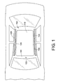
- FIGURE 1 is a schematic top plan view of a vehicle body including an exemplary embodiment of a roof support structure for a sunroof.
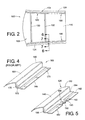
- FIGURE 2 is an enlarged top plan view of the roof support structure of FIGURE 1 shown with cross braces for supporting the sun roof.
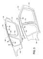
- FIGURE 3 is a perspective view of left and right side panel members of the vehicle body, the side panel members including top side roof rails for the roof support structure of FIGURE 1 .
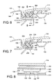
- FIGURE 4 is an enlarged partial perspective view of a portion of a known side panel member.
- FIGURE 5 is an enlarged partial perspective view of a portion of the right side panel member of FIGURE 3 taken generally along line 5-5 of FIGURE 3 to illustrate a corrugated section.
- FIGURE 6 is a cross-sectional view of the roof support structure taken generally along line 6-6 of FIGURE 2 .
- FIGURE 7 is a cross-sectional view of the roof support structure taken generally along line 7-7 of FIGURE 2 .
- FIGURE 8 is a cross-sectional view of the roof support structure taken generally along line 8-8 of FIGURE 6 .
- FIGURES 1 and 2 illustrate an exemplary embodiment of a roof support structure 100 for a vehicle body 102.
- the vehicle body 102 includes a roof 104 having a roof opening 106 that is closed by a cover member 110.
- the roof structure 100 is a sunroof assembly and the cover member 110 is a transparent member which is adhesively secured to a frame member 120.
- the frame member 120 is configured to frame the roof opening 106.
- the frame member 120 is adhesively secured to left and right side panel members 124 and 126, respectively, each side panel member forming a part of the vehicle body 102.
- the roof support structure 100 can further include roof rail braces 130 and 132 which span between the left and right side panel members 124 and 126. Opposed ends of each roof rail braces 130 and 132 are fixedly secured to the side panel members 124, 126.
- the vehicle body 102 can be a unibody construction, but can alternatively be constructed using any of a variety of other conventional construction techniques.
- each side panel member 124 and 126 can be mirror images of each other with respect to a centerline of the vehicle body 102.
- Each side panel member 124 and 126 includes an A-pillar region 140, a B-pillar region 142 and a C-pillar region 144.
- a top side roof rail 146 spans generally between the A-pillar region 140 and the C-pillar region 144.
- the top side roof rail 146 includes a top wall 150 having a peripheral edge portion 152.
- a generally vertical wall 156 separates the top wall 150 from the peripheral edge portion 152.
- the peripheral edge portion 152 has a stepped configuration such that the peripheral edge portion is bonded to a specific portion of the frame member 120 and is fixedly attached to a specific portion of the vehicle body 102 by conventional welding techniques, such as spot welding.
- the top side roof rail 160 includes a top wall 164 and a peripheral edge portion 166.
- the peripheral edge portion has a stepped configuration, including a first surface 170 and a second surface 172 which is elevated relative to the first surface.
- a generally vertical wall 176 separates the top wall 164 from the second surface 172.
- the first surface 170 is used as a welding flange for fixedly securing the side panel member 162 to the vehicle body.
- the first surface 170 is also adhesively attached (e.g., by a urethane adhesive) to a frame member of a roof support structure, such as frame member 120.
- At least one spacer member (not shown) is securely positioned between the frame member and the second surface 172 of the top side roof rail 160 at vertical positioning control locations.
- a bonding agent such as urethane adhesive, which is used to bond the first surface 170 to the frame member, can inadvertently flow between the spacer member and the top side roof rail 160. This can impact a final position of the roof support structure relative to the surrounding vehicle body, which can result in an undesirable fit condition.
- the exemplary peripheral edge portion 152 of the top side roof rail 146 of each side panel member 124 and 126 includes at least one channel 180 which defines a path adapted to allow escape of a bonding agent/adhesive that is disposed between the side panel member 124 or 126 and the frame member 120.
- the peripheral edge portion 152 includes a first surface 182 and a second surface 184 which is offset from the first surface 182. As shown, the second surface 184 is spaced inwardly from and is elevated relative to the first surface 182. The first and second surfaces 182 and 184 together define the channel 180.
- a section 186 of the peripheral edge portion 152 has a generally corrugated profile for allowing extra bonding agent disposed between the peripheral edge portion 152 of each side panel member 124, 126 and the frame member 120 to flow out of the sunroof assembly 100 which allows for ease of assembly of the sunroof assembly 100 to the vehicle body 102 by preventing the frame member 120 from sitting too high on the side panel members 124, 126.
- the second surface 184 intersects the first surface 182 at at least two spaced apart locations. The intersection of the first and second surfaces 182 and 184 defines the channel or path 180 for extra bonding agent to pass between the side panel member 124, 126 and the frame member 120.
- the second surface 184 includes at least one pair of spaced apart control surfaces 190 and 192.
- Each control surface 190 and 192 of the second surface 184 intersects the first surface 182. Because the first and second control surfaces 190, 192 are elevated relative to the first surface 182, the intersection of the pair of control surfaces 190, 192 and the first surface 182 defines the channel 180.
- each side panel member 124 and 126 of the illustrated embodiment includes three spaced apart generally corrugated sections 186, each section 186 including a channel 180 for the flow of extra adhesive disposed between the peripheral edge portion 152 of each side panel member 124, 126 and the frame member 120.
- FIGURES 6-8 illustrate the roof structure 100 in an assembled condition.
- the cover member or transparent member 110 is adhesively secured to the frame member 120 via a bonding agent or adhesive 200.
- a seal member 202 covers a gap between the top side roof rail 146 and the frame member 120 and covers a gap between the transparent member 110 and the frame member 120.
- the seal member 202 includes a bulbous portion 204 positioned between the transparent member 110 and the frame member 120 and a leg portion 206 positioned between the vertical wall 156 of the top side roof rail 146 and the frame member 120.
- the first surface 182 is fixedly secured to a portion of the vehicle body 102 such as a vehicle body stiffener 210 positioned at least partially beneath the frame member 120.
- the second surface 184 of the peripheral edge portion 156 is spaced from the body stiffener 210 and is adhesively secured to the frame member 120 via a bonding agent or adhesive 216. As shown in FIGURE 7 , the channel 180 defines the path for the bonding agent 216 to pass through the side panel member 124 without affecting a final fitting condition between the side panel member 124 and the frame member 120.
- At least one spacer member 220 is securely positioned between the frame member 120 and each side panel member 124 and 126. As shown in FIGURE 6 , a bottom surface 222 of the spacer member 220 abuts the second surface 184 of the side panel member and a top surface 224 of the spacer member 220 abuts the frame member 120.
- the channel 180 is configured to prevent the adhesive 216 from flowing between the spacer member 220 and the side panel member 124, 126. Particularly, as shown in FIGURE 8 , the spacer member 220 traverses or spans across the channel 180 and sits atop the control surfaces 190 and 192.
- the spacer member 220 is positioned between the frame member 120 and the corrugated section 186 of the peripheral edge portion 156. This arrangement prevents the adhesive 216 from being located between the top side roof rail 146 and the frame member 120.
- the roof structure or sunroof assembly 100 provides control surfaces 190 and 192 on the side panel members 124 and 126, which provides for a good final fitting condition. Using the peripheral edge portion 156 of each side panel member 124 and 126 as a datum, the number of tolerance contributors are minimized. Further, the sunroof assembly 100 is configured to provide a path 180 for extra urethane adhesive 216 to pass through the side panel members 124 and 126 without affecting the final fitting condition between the side panel members 124, 126 and the frame member 120.
- the section 186 of the peripheral edge portion 152 having the generally corrugated or bump shape also provides a strong support surface as compared to the conventional flat weld flange 170.
Landscapes
- Engineering & Computer Science (AREA)
- Chemical & Material Sciences (AREA)
- Combustion & Propulsion (AREA)
- Transportation (AREA)
- Mechanical Engineering (AREA)
- Body Structure For Vehicles (AREA)
Abstract
Description
- Exemplary embodiments herein relate to a vehicle roof structure, and, more particularly, to a side panel outer of a vehicle body including a body control surface for positioning of a sunroof assembly.
- One known vehicle roof assembly includes frame members supported by right and left side panel outer members of the vehicle body. In this assembly, the frame members define lateral sides of a sunroof opening and cross members span across the frame members. A sunroof cover (e.g., a framed glass pane) is supported over the sunroof opening by the frame members and the cross members. The side panel outer members each include traditional body-in-white flange surfaces for supporting the frame members, which in turn support the sunroof cover. Vertical spacers are sometimes interposed between the flange surfaces and the frame members at a plurality of vertical positioning locations disposed longitudinally along the flange surfaces.
- When an adhesive (e.g., a urethane adhesive) is used in the connection with the roof assembly described above, it is possible for the adhesive to undesirably lodge itself between the vertical spacers and the flange surfaces. This can adversely impact the final position of the roof assembly relative to the surrounding vehicle body. For example, the sunroof cover may not fit flush relative to the surrounding roof structure. In addition, the flange surfaces have no control surfaces (i.e., datum surfaces) for fitting of parts. This can also result in an undesirable fit condition.
- According to one aspect, a roof structure for a vehicle body is provided. The vehicle body includes a roof having a roof opening that is closed by a cover member. The roof structure comprises a frame member, a left side panel member and a right side panel member. The frame member is configured to frame the roof opening. The frame member supports the cover member. Each side panel member forms a part of the vehicle body and is adhesively secured to the frame member. A peripheral edge portion of each side panel member includes at least one channel adapted to allow escape of an adhesive disposed between the side panel member and the frame member for ease of assembly of the roof structure to the vehicle body.
- According to another aspect, a sunroof assembly for a vehicle body is provided. The vehicle body includes a roof having a roof opening. The sunroof assembly comprises a frame member which defines the roof opening. A transparent member covers the roof opening. The transparent member is bonded to the frame member. A vehicle body side panel member has a peripheral edge portion bonded to the frame member. A section of the peripheral edge portion has a generally corrugated profile for allowing extra bonding agent disposed between the peripheral edge portion of the side panel member and the frame member to flow out of the sunroof assembly. This allows for ease of assembly of the sunroof assembly to the vehicle body by preventing the frame member from sitting too high on the side panel member.
- According to yet another aspect, a sunroof assembly for a vehicle body is provided. The vehicle body includes a roof having a roof opening. The sunroof assembly comprises a frame member configured to frame the roof opening. A transparent member covers the roof opening. The transparent member is bonded to the frame member. A vehicle body side panel member has a peripheral edge portion bonded to the frame member. The peripheral edge portion has a stepped configuration and includes a first surface and a second surface. The second surface intersects the first surface at at least two spaced apart locations. The intersection of the first and second surfaces defines a path for extra bonding agent to pass through the side panel member without affecting a final fitting condition between the side panel member and the frame member.
-
FIGURE 1 is a schematic top plan view of a vehicle body including an exemplary embodiment of a roof support structure for a sunroof. -
FIGURE 2 is an enlarged top plan view of the roof support structure ofFIGURE 1 shown with cross braces for supporting the sun roof. -
FIGURE 3 is a perspective view of left and right side panel members of the vehicle body, the side panel members including top side roof rails for the roof support structure ofFIGURE 1 . -
FIGURE 4 is an enlarged partial perspective view of a portion of a known side panel member. -
FIGURE 5 is an enlarged partial perspective view of a portion of the right side panel member ofFIGURE 3 taken generally along line 5-5 ofFIGURE 3 to illustrate a corrugated section. -
FIGURE 6 is a cross-sectional view of the roof support structure taken generally along line 6-6 ofFIGURE 2 . -
FIGURE 7 is a cross-sectional view of the roof support structure taken generally along line 7-7 ofFIGURE 2 . -
FIGURE 8 is a cross-sectional view of the roof support structure taken generally along line 8-8 ofFIGURE 6 . - It should, of course, be understood that the description and drawings herein are merely illustrative and that various modifications and changes can be made in the structures disclosed without departing from the present disclosure. It will also be appreciated that the various identified components of the roof structure disclosed herein are merely terms of art that may vary from one vehicle manufacturer to another and should not be deemed to limit the present disclosure. All references to direction and position, unless otherwise indicated, refer to the orientation of the roof structure illustrated in the drawings and should not be construed as limiting the claims appended hereto. Like numerals refer to like parts throughout the several views.
- Referring now to the drawings wherein the showings are for purposes of illustrating one or more embodiments only and not for purposes of limiting the same,
FIGURES 1 and2 illustrate an exemplary embodiment of aroof support structure 100 for avehicle body 102. Thevehicle body 102 includes aroof 104 having a roof opening 106 that is closed by acover member 110. In the depicted embodiment, theroof structure 100 is a sunroof assembly and thecover member 110 is a transparent member which is adhesively secured to aframe member 120. Theframe member 120 is configured to frame theroof opening 106. Theframe member 120 is adhesively secured to left and rightside panel members vehicle body 102. As shown inFIGURE 2 , theroof support structure 100 can further includeroof rail braces side panel members roof rail braces side panel members vehicle body 102 can be a unibody construction, but can alternatively be constructed using any of a variety of other conventional construction techniques. - With reference to
FIGURE 3 , the left and rightside panel members vehicle body 102. Eachside panel member A-pillar region 140, a B-pillar region 142 and a C-pillar region 144. A topside roof rail 146 spans generally between the A-pillarregion 140 and the C-pillar region 144. The topside roof rail 146 includes atop wall 150 having aperipheral edge portion 152. A generallyvertical wall 156 separates thetop wall 150 from theperipheral edge portion 152. As will be discussed in greater detail below, theperipheral edge portion 152 has a stepped configuration such that the peripheral edge portion is bonded to a specific portion of theframe member 120 and is fixedly attached to a specific portion of thevehicle body 102 by conventional welding techniques, such as spot welding. - With reference to
FIGURE 4 , a portion of a topside roof rail 160 of a knownside panel member 162 is illustrated. The topside roof rail 160 includes atop wall 164 and aperipheral edge portion 166. The peripheral edge portion has a stepped configuration, including afirst surface 170 and asecond surface 172 which is elevated relative to the first surface. A generallyvertical wall 176 separates thetop wall 164 from thesecond surface 172. Thefirst surface 170 is used as a welding flange for fixedly securing theside panel member 162 to the vehicle body. Thefirst surface 170 is also adhesively attached (e.g., by a urethane adhesive) to a frame member of a roof support structure, such asframe member 120. At least one spacer member (not shown) is securely positioned between the frame member and thesecond surface 172 of the topside roof rail 160 at vertical positioning control locations. With this known topside roof rail 160, a bonding agent, such as urethane adhesive, which is used to bond thefirst surface 170 to the frame member, can inadvertently flow between the spacer member and the topside roof rail 160. This can impact a final position of the roof support structure relative to the surrounding vehicle body, which can result in an undesirable fit condition. - With reference to
FIGURE 5 , the exemplaryperipheral edge portion 152 of the topside roof rail 146 of eachside panel member channel 180 which defines a path adapted to allow escape of a bonding agent/adhesive that is disposed between theside panel member frame member 120. In the depicted embodiment, theperipheral edge portion 152 includes afirst surface 182 and asecond surface 184 which is offset from thefirst surface 182. As shown, thesecond surface 184 is spaced inwardly from and is elevated relative to thefirst surface 182. The first andsecond surfaces channel 180. - Particularly, a
section 186 of theperipheral edge portion 152 has a generally corrugated profile for allowing extra bonding agent disposed between theperipheral edge portion 152 of eachside panel member frame member 120 to flow out of thesunroof assembly 100 which allows for ease of assembly of thesunroof assembly 100 to thevehicle body 102 by preventing theframe member 120 from sitting too high on theside panel members section 186, thesecond surface 184 intersects thefirst surface 182 at at least two spaced apart locations. The intersection of the first andsecond surfaces path 180 for extra bonding agent to pass between theside panel member frame member 120. As shown, thesecond surface 184 includes at least one pair of spaced apart controlsurfaces control surface second surface 184 intersects thefirst surface 182. Because the first andsecond control surfaces first surface 182, the intersection of the pair ofcontrol surfaces first surface 182 defines thechannel 180. As shown inFIGURE 3 , eachside panel member sections 186, eachsection 186 including achannel 180 for the flow of extra adhesive disposed between theperipheral edge portion 152 of eachside panel member frame member 120. -
FIGURES 6-8 illustrate theroof structure 100 in an assembled condition. The cover member ortransparent member 110 is adhesively secured to theframe member 120 via a bonding agent or adhesive 200. Aseal member 202 covers a gap between the topside roof rail 146 and theframe member 120 and covers a gap between thetransparent member 110 and theframe member 120. Particularly, theseal member 202 includes abulbous portion 204 positioned between thetransparent member 110 and theframe member 120 and aleg portion 206 positioned between thevertical wall 156 of the topside roof rail 146 and theframe member 120. Thefirst surface 182 is fixedly secured to a portion of thevehicle body 102 such as avehicle body stiffener 210 positioned at least partially beneath theframe member 120. Thesecond surface 184 of theperipheral edge portion 156 is spaced from thebody stiffener 210 and is adhesively secured to theframe member 120 via a bonding agent or adhesive 216. As shown inFIGURE 7 , thechannel 180 defines the path for thebonding agent 216 to pass through theside panel member 124 without affecting a final fitting condition between theside panel member 124 and theframe member 120. - At least one
spacer member 220 is securely positioned between theframe member 120 and eachside panel member FIGURE 6 , abottom surface 222 of thespacer member 220 abuts thesecond surface 184 of the side panel member and atop surface 224 of thespacer member 220 abuts theframe member 120. Thechannel 180 is configured to prevent the adhesive 216 from flowing between thespacer member 220 and theside panel member FIGURE 8 , thespacer member 220 traverses or spans across thechannel 180 and sits atop thecontrol surfaces spacer member 220 is positioned between theframe member 120 and thecorrugated section 186 of theperipheral edge portion 156. This arrangement prevents the adhesive 216 from being located between the topside roof rail 146 and theframe member 120. - As is evident from the foregoing, the roof structure or
sunroof assembly 100 providescontrol surfaces side panel members peripheral edge portion 156 of eachside panel member sunroof assembly 100 is configured to provide apath 180 for extra urethane adhesive 216 to pass through theside panel members side panel members frame member 120. Thesection 186 of theperipheral edge portion 152 having the generally corrugated or bump shape also provides a strong support surface as compared to the conventionalflat weld flange 170. - It will be appreciated that various of the above-disclosed and other features and functions, or alternatives thereof, may be desirably combined into many other different systems or applications. Also that various presently unforeseen or unanticipated alternatives, modifications, variations or improvements therein may be subsequently made by those skilled in the art which are also intended to be encompassed by the following claims.
Claims (15)
- A roof structure for a vehicle body (102) including a roof (104) having a roof opening (106) that is closed by a cover member (110), the roof structure (100) comprising:a frame member (120) configured to frame the roof opening (106), the frame member (120) supporting the cover member (110); anda left side panel member (124) and a right side panel member (126), each side panel member (124, 126) forming a part of the vehicle body (102) and being adhesively secured to the frame member (120), a peripheral edge portion (152) of each side panel member (124, 126) including at least one channel (180) adapted to allow escape of an adhesive disposed between the side panel member (124, 126) and the frame member (120) for ease of assembly of the roof structure (100) to the vehicle body.
- The roof structure of claim 1, wherein the peripheral edge portion (152) of each side panel member (124, 126) includes a first surface (182) and a second surface (184) which is offset from the first surface (182), the first and second surfaces (182, 184) together defining the at least one channel (180).
- The roof structure of claim 2, wherein the second surface (184) is elevated relative to the first surface (182), the first surface (182) being fixedly secured to the vehicle body (102), the second surface (184) being adhesively secured to the frame member (120).
- The roof structure of claim 2, wherein the second surface (186) is spaced inwardly from the first surface (182).
- The roof structure of claim 4, wherein the second surface (184) includes at least one pair of spaced apart control surfaces (190, 192), each control surface (190, 192) intersecting the first surface (182), the at least one pair of control surfaces (190, 192) and the first surface (182) together defining the at least one channel (180).
- The roof structure of claim 1, wherein the cover member (110) is adhesively secured to the frame member (120).
- The roof structure of claim 1, wherein each side panel member (124, 126) includes three spaced apart channels.
- The roof structure of claim 1, further including at least one spacer member (220) securely positioned between the frame member (120) and each side panel member (124, 126), the at least one channel (180) configured to prevent the adhesive from flowing between the at least one spacer member (220) and the side panel member (124, 126).
- The roof structure of claim 8, wherein the at least one spacer member (220) spans across the at least one channel (180).
- The roof structure of claim 1, wherein each side panel member (124, 126) is fixedly secured to a vehicle body stiffener positioned at least partially beneath the frame member (120).
- A sunroof assembly for a vehicle body (102) including a roof (104) having a roof opening (106), the sunroof assembly comprising:a frame member (120) defining the roof opening (106);a transparent member for covering the roof opening (106), the transparent member being bonded to the frame member (120); anda vehicle body side panel member (124, 126) having a peripheral edge portion (152) bonded to the frame member (120), a section of the peripheral edge portion (152) having a generally corrugated profile for allowing extra bonding agent disposed between the peripheral edge portion (152) of the side panel member (124, 126) and the frame member (120) to flow out of the sunroof assembly (100) allowing for ease of assembly of the sunroof assembly (100) to the vehicle body (102) by preventing the frame member (120) from sitting too high on the side panel member (124, 126).
- The sunroof assembly of claim 11, wherein the generally corrugated section of the peripheral edge portion (152) defines a channel (180) for the flow of the bonding agent.
- The sunroof assembly of claim 12, further including a spacer member (220) securely positioned between the frame member (120) and the corrugated section, the spacer member (220) traversing the channel.
- The sunroof assembly of claim 11, wherein the peripheral edge portion (152) of the side panel member (124, 126) includes a first surface (182) and a second surface (184) which is elevated with respect to the first surface (182).
- The sunroof assembly of claim 14, wherein the first surface (182) is welded to the vehicle body (102) and the second surface (184) is bonded to the frame member (120).
Applications Claiming Priority (1)
| Application Number | Priority Date | Filing Date | Title |
|---|---|---|---|
| US12/481,228 US7810872B1 (en) | 2009-06-09 | 2009-06-09 | Sunroof support structure for a vehicle body |
Publications (2)
| Publication Number | Publication Date |
|---|---|
| EP2261103A1 true EP2261103A1 (en) | 2010-12-15 |
| EP2261103B1 EP2261103B1 (en) | 2012-08-22 |
Family
ID=42315677
Family Applications (1)
| Application Number | Title | Priority Date | Filing Date |
|---|---|---|---|
| EP10165331A Not-in-force EP2261103B1 (en) | 2009-06-09 | 2010-06-09 | Sunroof support structure for a vehicle body |
Country Status (5)
| Country | Link |
|---|---|
| US (1) | US7810872B1 (en) |
| EP (1) | EP2261103B1 (en) |
| JP (1) | JP2010285143A (en) |
| CN (1) | CN101920647B (en) |
| ES (1) | ES2389884T3 (en) |
Families Citing this family (4)
| Publication number | Priority date | Publication date | Assignee | Title |
|---|---|---|---|---|
| US7922241B2 (en) * | 2008-07-30 | 2011-04-12 | Simco Automotive | Sunshade with adjustable slide portion |
| DE102013009072A1 (en) * | 2013-05-29 | 2014-12-04 | Audi Ag | Roof structure for a vehicle body |
| CN103738148A (en) * | 2014-01-22 | 2014-04-23 | 安徽江淮汽车股份有限公司 | Top-cover outer plate and skylight reinforcing frame structure |
| EP3140177B1 (en) | 2014-05-06 | 2019-10-30 | Magna Exteriors Inc. | Roof attachment method for an applied composition roof |
Citations (3)
| Publication number | Priority date | Publication date | Assignee | Title |
|---|---|---|---|---|
| DE10109646A1 (en) * | 2001-02-28 | 2002-09-05 | Volkswagen Ag | Motor vehicle of modular construction with roof module connected to body module via adhesive along engaging edges |
| WO2004048154A1 (en) * | 2002-11-22 | 2004-06-10 | Daimlerchysler Ag | Precisely spaced assembly of a roof module and a vehicle body |
| US20080100100A1 (en) * | 2006-10-31 | 2008-05-01 | Classic Design Concepts, Llc | Vehicle Roof Assembly and Method of Installing a Vehicle Roof Assembly on a Vehicle |
Family Cites Families (20)
| Publication number | Priority date | Publication date | Assignee | Title |
|---|---|---|---|---|
| NL241505A (en) | 1958-07-22 | |||
| JPS58180719U (en) * | 1982-05-29 | 1983-12-02 | 富士重工業株式会社 | Automobile back door hinge mounting structure |
| JPS61196820A (en) * | 1985-02-26 | 1986-09-01 | Dainichi Kosan Kk | Cover holding device for car body sunshade |
| JPS61196818A (en) * | 1985-02-27 | 1986-09-01 | Nissan Motor Co Ltd | Wind panel setting structure |
| US4892351A (en) | 1987-03-13 | 1990-01-09 | Honda Giken Kogyo K.K. | Water drain trough for automotive sunroof |
| US4989912A (en) * | 1988-10-31 | 1991-02-05 | General Motors Corporation | Window retention apparatus |
| US5029933A (en) * | 1989-11-27 | 1991-07-09 | Gillem Vernon A | Car cover |
| JPH06340227A (en) * | 1993-05-31 | 1994-12-13 | Kaoru Matsuoka | Cover device for automobile |
| US5669657A (en) | 1994-12-13 | 1997-09-23 | Hori Glass Co., Ltd. | Sunroof assembly for motor vehicle |
| DE19738829C1 (en) | 1997-09-05 | 1999-02-18 | Daimler Benz Ag | Roof arrangement consisting of two roof parts |
| DE19919505A1 (en) * | 1999-04-29 | 2000-11-02 | Webasto Vehicle Sys Int Gmbh | Vehicle roof with inserted roof module and assembly process for it |
| DE19949468B4 (en) | 1999-10-11 | 2005-06-16 | Webasto Ag | Vehicle roof with roof module |
| JP4284793B2 (en) | 1999-11-17 | 2009-06-24 | マツダ株式会社 | Upper body structure of the vehicle |
| DE50013758D1 (en) | 2000-06-05 | 2006-12-28 | Webasto Vehicle Sys Int Gmbh | MODULE ROOF OF A MOTOR VEHICLE |
| DE10158401B4 (en) * | 2001-11-28 | 2004-07-15 | Daimlerchrysler Ag | Moduldach for a motor vehicle and method for its assembly |
| DE10319442B4 (en) | 2003-04-30 | 2006-10-19 | Daimlerchrysler Ag | Assembly, corresponding frame module and corresponding frame structure |
| EP1669245A1 (en) | 2004-12-08 | 2006-06-14 | ArvinMeritor GmbH | Roof module for a vehicle |
| US7213874B2 (en) | 2005-03-09 | 2007-05-08 | Nissan Technical Center North America, Inc. | Vehicle roof structure |
| JP2007283841A (en) * | 2006-04-14 | 2007-11-01 | Nissan Motor Co Ltd | Body panel joint structure |
| CN201086625Y (en) * | 2007-07-26 | 2008-07-16 | 余汉生 | Foldable and portable exterior sun shield for automobile |
-
2009
- 2009-06-09 US US12/481,228 patent/US7810872B1/en not_active Expired - Fee Related
-
2010
- 2010-04-26 JP JP2010101190A patent/JP2010285143A/en not_active Ceased
- 2010-05-25 CN CN201010189357.0A patent/CN101920647B/en not_active Expired - Fee Related
- 2010-06-09 ES ES10165331T patent/ES2389884T3/en active Active
- 2010-06-09 EP EP10165331A patent/EP2261103B1/en not_active Not-in-force
Patent Citations (3)
| Publication number | Priority date | Publication date | Assignee | Title |
|---|---|---|---|---|
| DE10109646A1 (en) * | 2001-02-28 | 2002-09-05 | Volkswagen Ag | Motor vehicle of modular construction with roof module connected to body module via adhesive along engaging edges |
| WO2004048154A1 (en) * | 2002-11-22 | 2004-06-10 | Daimlerchysler Ag | Precisely spaced assembly of a roof module and a vehicle body |
| US20080100100A1 (en) * | 2006-10-31 | 2008-05-01 | Classic Design Concepts, Llc | Vehicle Roof Assembly and Method of Installing a Vehicle Roof Assembly on a Vehicle |
Also Published As
| Publication number | Publication date |
|---|---|
| CN101920647A (en) | 2010-12-22 |
| ES2389884T3 (en) | 2012-11-02 |
| CN101920647B (en) | 2014-07-02 |
| US7810872B1 (en) | 2010-10-12 |
| EP2261103B1 (en) | 2012-08-22 |
| JP2010285143A (en) | 2010-12-24 |
Similar Documents
| Publication | Publication Date | Title |
|---|---|---|
| CN105882760B (en) | Upper vehicle body structure of vehicle | |
| US7407222B2 (en) | Vehicle body structure | |
| US7914072B2 (en) | Moon roof frame module for reinforcement of automotive roof | |
| CN105377674B (en) | Body top section structure | |
| US20070145773A1 (en) | Vehicle rear door and method of assembling same | |
| US20130187406A1 (en) | Vehicle body structure | |
| CN108657284A (en) | Front standing pillar constructs and vehicle | |
| JP5881813B2 (en) | Railway vehicle | |
| JP6188761B2 (en) | Body front structure | |
| US7810872B1 (en) | Sunroof support structure for a vehicle body | |
| US7677652B2 (en) | Roof inner body structure | |
| JP2019034643A (en) | Body superstructure | |
| CN110481579B (en) | Structures for railway vehicles | |
| US11548554B2 (en) | Vehicle rear portion structure | |
| US20220073146A1 (en) | Vehicle roof structure | |
| JP2019089488A (en) | Vehicle body skeleton structure | |
| JP6453000B2 (en) | Vehicle door frame | |
| JP2005132214A (en) | Roof structure for automobile | |
| CN111252144B (en) | Front pillar structure | |
| JP6107209B2 (en) | Roof side rail structure | |
| US11472272B2 (en) | Vehicle entrance structure | |
| JP2016088462A (en) | Vehicle body upper part structure | |
| JP4731283B2 (en) | Railway vehicle body structure | |
| CN108502024B (en) | Vehicle roof structure | |
| JP5567359B2 (en) | Railway vehicle structure and manufacturing method thereof |
Legal Events
| Date | Code | Title | Description |
|---|---|---|---|
| PUAI | Public reference made under article 153(3) epc to a published international application that has entered the european phase |
Free format text: ORIGINAL CODE: 0009012 |
|
| AK | Designated contracting states |
Kind code of ref document: A1 Designated state(s): AL AT BE BG CH CY CZ DE DK EE ES FI FR GB GR HR HU IE IS IT LI LT LU LV MC MK MT NL NO PL PT RO SE SI SK SM TR |
|
| AX | Request for extension of the european patent |
Extension state: BA ME RS |
|
| 17P | Request for examination filed |
Effective date: 20110504 |
|
| GRAP | Despatch of communication of intention to grant a patent |
Free format text: ORIGINAL CODE: EPIDOSNIGR1 |
|
| GRAS | Grant fee paid |
Free format text: ORIGINAL CODE: EPIDOSNIGR3 |
|
| GRAA | (expected) grant |
Free format text: ORIGINAL CODE: 0009210 |
|
| AK | Designated contracting states |
Kind code of ref document: B1 Designated state(s): AL AT BE BG CH CY CZ DE DK EE ES FI FR GB GR HR HU IE IS IT LI LT LU LV MC MK MT NL NO PL PT RO SE SI SK SM TR |
|
| REG | Reference to a national code |
Ref country code: GB Ref legal event code: FG4D |
|
| REG | Reference to a national code |
Ref country code: CH Ref legal event code: EP |
|
| REG | Reference to a national code |
Ref country code: IE Ref legal event code: FG4D |
|
| REG | Reference to a national code |
Ref country code: AT Ref legal event code: REF Ref document number: 571809 Country of ref document: AT Kind code of ref document: T Effective date: 20120915 |
|
| REG | Reference to a national code |
Ref country code: DE Ref legal event code: R096 Ref document number: 602010002408 Country of ref document: DE Effective date: 20121018 |
|
| REG | Reference to a national code |
Ref country code: ES Ref legal event code: FG2A Ref document number: 2389884 Country of ref document: ES Kind code of ref document: T3 Effective date: 20121102 |
|
| REG | Reference to a national code |
Ref country code: NL Ref legal event code: VDEP Effective date: 20120822 |
|
| REG | Reference to a national code |
Ref country code: AT Ref legal event code: MK05 Ref document number: 571809 Country of ref document: AT Kind code of ref document: T Effective date: 20120822 |
|
| REG | Reference to a national code |
Ref country code: LT Ref legal event code: MG4D Effective date: 20120822 |
|
| PG25 | Lapsed in a contracting state [announced via postgrant information from national office to epo] |
Ref country code: HR Free format text: LAPSE BECAUSE OF FAILURE TO SUBMIT A TRANSLATION OF THE DESCRIPTION OR TO PAY THE FEE WITHIN THE PRESCRIBED TIME-LIMIT Effective date: 20120822 Ref country code: AT Free format text: LAPSE BECAUSE OF FAILURE TO SUBMIT A TRANSLATION OF THE DESCRIPTION OR TO PAY THE FEE WITHIN THE PRESCRIBED TIME-LIMIT Effective date: 20120822 Ref country code: IS Free format text: LAPSE BECAUSE OF FAILURE TO SUBMIT A TRANSLATION OF THE DESCRIPTION OR TO PAY THE FEE WITHIN THE PRESCRIBED TIME-LIMIT Effective date: 20121222 Ref country code: NO Free format text: LAPSE BECAUSE OF FAILURE TO SUBMIT A TRANSLATION OF THE DESCRIPTION OR TO PAY THE FEE WITHIN THE PRESCRIBED TIME-LIMIT Effective date: 20121122 Ref country code: FI Free format text: LAPSE BECAUSE OF FAILURE TO SUBMIT A TRANSLATION OF THE DESCRIPTION OR TO PAY THE FEE WITHIN THE PRESCRIBED TIME-LIMIT Effective date: 20120822 Ref country code: LT Free format text: LAPSE BECAUSE OF FAILURE TO SUBMIT A TRANSLATION OF THE DESCRIPTION OR TO PAY THE FEE WITHIN THE PRESCRIBED TIME-LIMIT Effective date: 20120822 |
|
| PG25 | Lapsed in a contracting state [announced via postgrant information from national office to epo] |
Ref country code: GR Free format text: LAPSE BECAUSE OF FAILURE TO SUBMIT A TRANSLATION OF THE DESCRIPTION OR TO PAY THE FEE WITHIN THE PRESCRIBED TIME-LIMIT Effective date: 20121123 Ref country code: LV Free format text: LAPSE BECAUSE OF FAILURE TO SUBMIT A TRANSLATION OF THE DESCRIPTION OR TO PAY THE FEE WITHIN THE PRESCRIBED TIME-LIMIT Effective date: 20120822 Ref country code: BE Free format text: LAPSE BECAUSE OF FAILURE TO SUBMIT A TRANSLATION OF THE DESCRIPTION OR TO PAY THE FEE WITHIN THE PRESCRIBED TIME-LIMIT Effective date: 20120822 Ref country code: SE Free format text: LAPSE BECAUSE OF FAILURE TO SUBMIT A TRANSLATION OF THE DESCRIPTION OR TO PAY THE FEE WITHIN THE PRESCRIBED TIME-LIMIT Effective date: 20120822 Ref country code: SI Free format text: LAPSE BECAUSE OF FAILURE TO SUBMIT A TRANSLATION OF THE DESCRIPTION OR TO PAY THE FEE WITHIN THE PRESCRIBED TIME-LIMIT Effective date: 20120822 Ref country code: PT Free format text: LAPSE BECAUSE OF FAILURE TO SUBMIT A TRANSLATION OF THE DESCRIPTION OR TO PAY THE FEE WITHIN THE PRESCRIBED TIME-LIMIT Effective date: 20121224 |
|
| PG25 | Lapsed in a contracting state [announced via postgrant information from national office to epo] |
Ref country code: NL Free format text: LAPSE BECAUSE OF FAILURE TO SUBMIT A TRANSLATION OF THE DESCRIPTION OR TO PAY THE FEE WITHIN THE PRESCRIBED TIME-LIMIT Effective date: 20120822 |
|
| PG25 | Lapsed in a contracting state [announced via postgrant information from national office to epo] |
Ref country code: RO Free format text: LAPSE BECAUSE OF FAILURE TO SUBMIT A TRANSLATION OF THE DESCRIPTION OR TO PAY THE FEE WITHIN THE PRESCRIBED TIME-LIMIT Effective date: 20120822 Ref country code: DK Free format text: LAPSE BECAUSE OF FAILURE TO SUBMIT A TRANSLATION OF THE DESCRIPTION OR TO PAY THE FEE WITHIN THE PRESCRIBED TIME-LIMIT Effective date: 20120822 Ref country code: EE Free format text: LAPSE BECAUSE OF FAILURE TO SUBMIT A TRANSLATION OF THE DESCRIPTION OR TO PAY THE FEE WITHIN THE PRESCRIBED TIME-LIMIT Effective date: 20120822 Ref country code: CZ Free format text: LAPSE BECAUSE OF FAILURE TO SUBMIT A TRANSLATION OF THE DESCRIPTION OR TO PAY THE FEE WITHIN THE PRESCRIBED TIME-LIMIT Effective date: 20120822 |
|
| PG25 | Lapsed in a contracting state [announced via postgrant information from national office to epo] |
Ref country code: SK Free format text: LAPSE BECAUSE OF FAILURE TO SUBMIT A TRANSLATION OF THE DESCRIPTION OR TO PAY THE FEE WITHIN THE PRESCRIBED TIME-LIMIT Effective date: 20120822 Ref country code: PL Free format text: LAPSE BECAUSE OF FAILURE TO SUBMIT A TRANSLATION OF THE DESCRIPTION OR TO PAY THE FEE WITHIN THE PRESCRIBED TIME-LIMIT Effective date: 20120822 |
|
| PLBE | No opposition filed within time limit |
Free format text: ORIGINAL CODE: 0009261 |
|
| STAA | Information on the status of an ep patent application or granted ep patent |
Free format text: STATUS: NO OPPOSITION FILED WITHIN TIME LIMIT |
|
| 26N | No opposition filed |
Effective date: 20130523 |
|
| PG25 | Lapsed in a contracting state [announced via postgrant information from national office to epo] |
Ref country code: BG Free format text: LAPSE BECAUSE OF FAILURE TO SUBMIT A TRANSLATION OF THE DESCRIPTION OR TO PAY THE FEE WITHIN THE PRESCRIBED TIME-LIMIT Effective date: 20121122 |
|
| REG | Reference to a national code |
Ref country code: DE Ref legal event code: R097 Ref document number: 602010002408 Country of ref document: DE Effective date: 20130523 |
|
| PG25 | Lapsed in a contracting state [announced via postgrant information from national office to epo] |
Ref country code: CY Free format text: LAPSE BECAUSE OF FAILURE TO SUBMIT A TRANSLATION OF THE DESCRIPTION OR TO PAY THE FEE WITHIN THE PRESCRIBED TIME-LIMIT Effective date: 20120822 |
|
| PG25 | Lapsed in a contracting state [announced via postgrant information from national office to epo] |
Ref country code: MC Free format text: LAPSE BECAUSE OF FAILURE TO SUBMIT A TRANSLATION OF THE DESCRIPTION OR TO PAY THE FEE WITHIN THE PRESCRIBED TIME-LIMIT Effective date: 20120822 |
|
| REG | Reference to a national code |
Ref country code: IE Ref legal event code: MM4A |
|
| PG25 | Lapsed in a contracting state [announced via postgrant information from national office to epo] |
Ref country code: IE Free format text: LAPSE BECAUSE OF NON-PAYMENT OF DUE FEES Effective date: 20130609 |
|
| PGFP | Annual fee paid to national office [announced via postgrant information from national office to epo] |
Ref country code: GB Payment date: 20140604 Year of fee payment: 5 |
|
| PGFP | Annual fee paid to national office [announced via postgrant information from national office to epo] |
Ref country code: ES Payment date: 20140513 Year of fee payment: 5 Ref country code: IT Payment date: 20140623 Year of fee payment: 5 |
|
| PGFP | Annual fee paid to national office [announced via postgrant information from national office to epo] |
Ref country code: FR Payment date: 20140609 Year of fee payment: 5 |
|
| REG | Reference to a national code |
Ref country code: CH Ref legal event code: PL |
|
| PG25 | Lapsed in a contracting state [announced via postgrant information from national office to epo] |
Ref country code: MT Free format text: LAPSE BECAUSE OF FAILURE TO SUBMIT A TRANSLATION OF THE DESCRIPTION OR TO PAY THE FEE WITHIN THE PRESCRIBED TIME-LIMIT Effective date: 20120822 |
|
| PG25 | Lapsed in a contracting state [announced via postgrant information from national office to epo] |
Ref country code: LI Free format text: LAPSE BECAUSE OF NON-PAYMENT OF DUE FEES Effective date: 20140630 Ref country code: CH Free format text: LAPSE BECAUSE OF NON-PAYMENT OF DUE FEES Effective date: 20140630 |
|
| PG25 | Lapsed in a contracting state [announced via postgrant information from national office to epo] |
Ref country code: SM Free format text: LAPSE BECAUSE OF FAILURE TO SUBMIT A TRANSLATION OF THE DESCRIPTION OR TO PAY THE FEE WITHIN THE PRESCRIBED TIME-LIMIT Effective date: 20120822 |
|
| PG25 | Lapsed in a contracting state [announced via postgrant information from national office to epo] |
Ref country code: TR Free format text: LAPSE BECAUSE OF FAILURE TO SUBMIT A TRANSLATION OF THE DESCRIPTION OR TO PAY THE FEE WITHIN THE PRESCRIBED TIME-LIMIT Effective date: 20120822 |
|
| PG25 | Lapsed in a contracting state [announced via postgrant information from national office to epo] |
Ref country code: MK Free format text: LAPSE BECAUSE OF FAILURE TO SUBMIT A TRANSLATION OF THE DESCRIPTION OR TO PAY THE FEE WITHIN THE PRESCRIBED TIME-LIMIT Effective date: 20120822 Ref country code: LU Free format text: LAPSE BECAUSE OF NON-PAYMENT OF DUE FEES Effective date: 20130609 Ref country code: HU Free format text: LAPSE BECAUSE OF FAILURE TO SUBMIT A TRANSLATION OF THE DESCRIPTION OR TO PAY THE FEE WITHIN THE PRESCRIBED TIME-LIMIT; INVALID AB INITIO Effective date: 20100609 |
|
| PGFP | Annual fee paid to national office [announced via postgrant information from national office to epo] |
Ref country code: DE Payment date: 20150602 Year of fee payment: 6 |
|
| PG25 | Lapsed in a contracting state [announced via postgrant information from national office to epo] |
Ref country code: IT Free format text: LAPSE BECAUSE OF NON-PAYMENT OF DUE FEES Effective date: 20150609 |
|
| GBPC | Gb: european patent ceased through non-payment of renewal fee |
Effective date: 20150609 |
|
| REG | Reference to a national code |
Ref country code: FR Ref legal event code: ST Effective date: 20160229 |
|
| PG25 | Lapsed in a contracting state [announced via postgrant information from national office to epo] |
Ref country code: GB Free format text: LAPSE BECAUSE OF NON-PAYMENT OF DUE FEES Effective date: 20150609 |
|
| PG25 | Lapsed in a contracting state [announced via postgrant information from national office to epo] |
Ref country code: FR Free format text: LAPSE BECAUSE OF NON-PAYMENT OF DUE FEES Effective date: 20150630 |
|
| REG | Reference to a national code |
Ref country code: ES Ref legal event code: FD2A Effective date: 20160727 |
|
| PG25 | Lapsed in a contracting state [announced via postgrant information from national office to epo] |
Ref country code: ES Free format text: LAPSE BECAUSE OF NON-PAYMENT OF DUE FEES Effective date: 20150610 |
|
| REG | Reference to a national code |
Ref country code: DE Ref legal event code: R119 Ref document number: 602010002408 Country of ref document: DE |
|
| PG25 | Lapsed in a contracting state [announced via postgrant information from national office to epo] |
Ref country code: DE Free format text: LAPSE BECAUSE OF NON-PAYMENT OF DUE FEES Effective date: 20170103 |
|
| PG25 | Lapsed in a contracting state [announced via postgrant information from national office to epo] |
Ref country code: AL Free format text: LAPSE BECAUSE OF FAILURE TO SUBMIT A TRANSLATION OF THE DESCRIPTION OR TO PAY THE FEE WITHIN THE PRESCRIBED TIME-LIMIT Effective date: 20120822 |