EP2260765B1 - Non-contact ultrasonic measurement device - Google Patents
Non-contact ultrasonic measurement device Download PDFInfo
- Publication number
- EP2260765B1 EP2260765B1 EP10165412A EP10165412A EP2260765B1 EP 2260765 B1 EP2260765 B1 EP 2260765B1 EP 10165412 A EP10165412 A EP 10165412A EP 10165412 A EP10165412 A EP 10165412A EP 2260765 B1 EP2260765 B1 EP 2260765B1
- Authority
- EP
- European Patent Office
- Prior art keywords
- eye
- measurement
- unit
- optical system
- transmitting
- Prior art date
- Legal status (The legal status is an assumption and is not a legal conclusion. Google has not performed a legal analysis and makes no representation as to the accuracy of the status listed.)
- Not-in-force
Links
- 238000005259 measurement Methods 0.000 title claims description 82
- 230000003287 optical effect Effects 0.000 claims description 94
- 238000002604 ultrasonography Methods 0.000 claims description 36
- 210000004087 cornea Anatomy 0.000 claims description 34
- 230000004410 intraocular pressure Effects 0.000 claims description 22
- 238000000034 method Methods 0.000 claims description 2
- 238000003384 imaging method Methods 0.000 description 15
- 238000005286 illumination Methods 0.000 description 5
- 238000001514 detection method Methods 0.000 description 4
- 238000009530 blood pressure measurement Methods 0.000 description 3
- 239000007789 gas Substances 0.000 description 3
- 230000002452 interceptive effect Effects 0.000 description 3
- 230000005540 biological transmission Effects 0.000 description 2
- 210000000399 corneal endothelial cell Anatomy 0.000 description 2
- 238000010586 diagram Methods 0.000 description 2
- 230000000694 effects Effects 0.000 description 2
- 210000002159 anterior chamber Anatomy 0.000 description 1
- 230000004323 axial length Effects 0.000 description 1
- 210000001110 axial length eye Anatomy 0.000 description 1
- 230000001419 dependent effect Effects 0.000 description 1
- 238000011161 development Methods 0.000 description 1
- 230000018109 developmental process Effects 0.000 description 1
- 230000006870 function Effects 0.000 description 1
- 239000011521 glass Substances 0.000 description 1
- 230000001939 inductive effect Effects 0.000 description 1
- 239000011261 inert gas Substances 0.000 description 1
- 238000012986 modification Methods 0.000 description 1
- 230000004048 modification Effects 0.000 description 1
- 230000002093 peripheral effect Effects 0.000 description 1
- 210000001747 pupil Anatomy 0.000 description 1
- 230000005855 radiation Effects 0.000 description 1
- 238000012360 testing method Methods 0.000 description 1
Images

Classifications
-
- A—HUMAN NECESSITIES
- A61—MEDICAL OR VETERINARY SCIENCE; HYGIENE
- A61B—DIAGNOSIS; SURGERY; IDENTIFICATION
- A61B8/00—Diagnosis using ultrasonic, sonic or infrasonic waves
- A61B8/10—Eye inspection
-
- A—HUMAN NECESSITIES
- A61—MEDICAL OR VETERINARY SCIENCE; HYGIENE
- A61B—DIAGNOSIS; SURGERY; IDENTIFICATION
- A61B3/00—Apparatus for testing the eyes; Instruments for examining the eyes
- A61B3/10—Objective types, i.e. instruments for examining the eyes independent of the patients' perceptions or reactions
- A61B3/14—Arrangements specially adapted for eye photography
- A61B3/15—Arrangements specially adapted for eye photography with means for aligning, spacing or blocking spurious reflection ; with means for relaxing
- A61B3/152—Arrangements specially adapted for eye photography with means for aligning, spacing or blocking spurious reflection ; with means for relaxing for aligning
-
- A—HUMAN NECESSITIES
- A61—MEDICAL OR VETERINARY SCIENCE; HYGIENE
- A61B—DIAGNOSIS; SURGERY; IDENTIFICATION
- A61B3/00—Apparatus for testing the eyes; Instruments for examining the eyes
- A61B3/10—Objective types, i.e. instruments for examining the eyes independent of the patients' perceptions or reactions
- A61B3/16—Objective types, i.e. instruments for examining the eyes independent of the patients' perceptions or reactions for measuring intraocular pressure, e.g. tonometers
- A61B3/165—Non-contacting tonometers
Definitions
- the present invention relates to a non-contact ultrasound measurement device for measuring characteristics of an object to be examined non-contactively by use of ultrasonic waves.
- Non-contact ultrasound tonometer including a transducer having a vibrator for emitting an ultrasonic wave toward a cornea of an examinee's eye and a sensor for detecting the ultrasonic wave reflected by the cornea to measure intraocular pressure of the eye in a non-contact manner (see Patent Literature 1).
- Patent Literature 2 forms the closest prior art document. It describes how a beam of acoustic energy comprising acoustic radiation and the associated acoustic streaming of an ultrasonic beam is used to indent or applanate (flatten) the eye. These two effects produce acoustic pressure on the eye which partially overcomes the IOP of the eye. Such concurrent determination of acoustic pressure and distortion of the eye is then used to determine the IOP.
- Patent Literature 1 WO 2008/072527
- Patent Literature 2 US 5 865 135 A .
- the ultrasound measurement device mentioned above is preferably arranged to enable good observation of the object located in a position away from the device.
- the ultrasound measurement device is further preferably arranged to enable good measurement of various data on the object.
- the device in Patent Literature 1 is designed to merely measure a schematic eye.
- Such device is still insufficient to measure a real human eye and has many problems to be solved for practical use.
- a certain degree of a working distance e.g., about 10 mm
- this device could not measure second eye characteristic different from the intraocular pressure.
- the present invention has a purpose to provide a non-contact ultrasound measurement device capable of accurately measuring a first characteristic of an object to be examined and appropriately observing the object or measuring a second characteristic of the object.
- the present invention provides a non-contact ultrasound measurement device according to claim 1. Further developments of the present invention are given in the dependent claims.
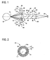
- FIG. 1 is a schematic configuration view of a measurement system and an optical system of a non-contact ultrasound tonometer which is a non-contact ultrasound measurement device in this embodiment.
- the following measurement system and optical system are built in a housing not shown.
- This housing may be moved three-dimensionally relative to an examinee's eye by a known movement mechanism for alignment or may be a handheld type (handy type).
- An ultrasound transducer 10 emits an ultrasonic wave (a pulse wave or a continuous wave) toward a cornea Ec of the examinee's eye E by the medium of air and also detects the ultrasonic wave reflected by the cornea Ec.
- the transducer 10 includes, as a transmitting and receiving part 11 of ultrasonic wave, a transmitting section 12 for emitting an ultrasonic wave and a receiving section 13 for detecting a reflection wave from the cornea Ec.
- the transducer 10 is used for measuring intraocular pressure in a non-contact manner.
- the transmitting section 12 and the receiving section 13 are separately configured and placed in different positions, but they are not limited to such configuration and may be shared.
- the optical system of the device includes an observation optical system 20 for observing an anterior segment of the eye E from front, a fixation target projecting (presenting) optical system 30 for inducing the eye E to hold fixation, a first target projecting optical system 40 for projecting a first target onto the cornea Ec to detect an alignment state in up-down and right-left directions, a second target projecting optical system 50 for projecting a second target onto the cornea Ec to detect an alignment state in a working distance which is a front-rear direction, and a target detecting optical system 55 for detecting the second target projected onto the cornea Ec.
- an observation optical system 20 for observing an anterior segment of the eye E from front
- a fixation target projecting (presenting) optical system 30 for inducing the eye E to hold fixation
- a first target projecting optical system 40 for projecting a first target onto the cornea Ec to detect an alignment state in up-down and right-left directions
- a second target projecting optical system 50 for projecting a second target onto the cornea Ec to detect an alignment state
- the observation optical system 20 includes an objective lens 22, an image forming lens 24, and a two-dimensionally imaging element 26.
- This optical system 20 is placed so that its optical axis (an observation optical axis) L1 is almost coaxial with a central axis of the transmitting and receiving part 11. Accordingly, when the observation optical axis L1 is aligned with respect to a predetermined portion (e.g., the center of a cornea, the center of a pupil) of the eye E, the transducer 10 is aligned in up-down and right-left directions relative to the eye E.
- a predetermined portion e.g., the center of a cornea, the center of a pupil
- An image of the anterior segment illuminated by an infrared light source 38 passes through an aperture 15, the objective lens 22, a half mirror 46, and a dichroic mirror 36 in order and then forms an image on the imaging element 26 through the image forming lens 24.
- the anterior segment image imaged by the imaging element 26 is displayed on a monitor 72 mentioned later.
- the fixation target projecting optical system 30 includes a visible light source 32 to project a fixation target onto the eye E to induce the eye E to hold fixation. Visible light from the light source 32 is reflected by the dichroic mirror 36 that transmits infrared light but reflects visible light. This light then passes through the half mirror 46 and the objective lens 22 and is projected onto a fundus of the eye E.
- An optical axis L2 of the fixation target projecting optical system 30 is made coaxial with the observation optical axis L1 by the dichroic mirror 36 placed in the optical path (the observation optical path) of the observation optical system 20.
- the first target projecting optical system 40 includes an infrared light source 42 and projects infrared light onto the cornea Ec from front so that the infrared light forms the first target for detecting the alignment state in the up-down and right-left directions.
- the infrared light from the light source 42 is reflected by the half mirror 46, passes through the objective lens 22, and is projected onto the cornea Ec.
- An optical axis L3 of the first target projecting optical system 40 is made coaxial with the observation optical axis L1 by the half mirror 46 placed in the observation optical path (the optical path of the observation light).
- the observation optical system 20 detects the first target formed on the cornea Ec (i.e., the optical system 20 receives the infrared light that is emitted from the light source 42 and reflected by the cornea Ec) by the first target projecting optical system 40. In other words, the observation optical system 20 is also used as a target detecting optical system.
- the first target image imaged by the imaging element 26 is displayed on the monitor 72 (see a point image I in FIG. 3 ).
- the second target projecting optical system 50 includes an infrared light source 51 and obliquely projects infrared light onto the cornea Ec so that the infrared light forms a second target for detecting an alignment state in the working distance direction.
- the target detecting optical system 55 includes a position detecting device (e.g., a line CCD) 58 and detects the second target image formed on the cornea Ec by the second target projecting optical system 50 (i.e., the optical system 55 receives the infrared light that is emitted from the light source 51 and reflected by the cornea Ec). It is to be noted that detection of the alignment state in the working distance direction may be conducted by the transducer 10. For example, the time until an ultrasonic wave emitted to the examinee's eye returns to the transducer 10 is converted into distance.
- a position detecting device e.g., a line CCD
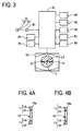
- FIG. 2 is a schematic configuration view of the transducer 10 seen from front in the present embodiment.
- the transducer 10 centrally includes the aperture 15 having a sufficient size to be used as an observation optical path and the transmitting and receiving part 11 is placed to surround the aperture 15.
- the base part 10a is formed with a through hole having an inside diameter corresponding to the aperture 15, and the transmitting and receiving part 11 is placed on the base part 10a on a side facing the eye E and in an almost annular form outside the through hole.
- the transmitting section 12 and the receiving section 13 are placed concentrically in different positions.
- the transmitting section 12 is located outside and the receiving section 13 is located inside.
- the receiving section 13 may be placed outside and the transmitting section 12 may be inside.
- the objective lens 22 is placed in the aperture 15. It is to be understood that other optical member(s) (e.g., a glass plate, a filter, etc.) may be placed in the aperture 15 or the optical member as mentioned above may not be placed in the aperture 15.
- other optical member(s) e.g., a glass plate, a filter, etc.
- the aperture 15 has a size enough for observation of the examinee's eye by the observation optical system 20 to ensure an observation range in a permissible range by the observation optical system 20.
- the size of the aperture 15 (the inside diameter of the through hole of the base part 10a) is appropriately determined by considering whether or not alignment with respect to the examinee's eye is smoothly performed, whether or not a state of the anterior segment is observed well, or others.
- the shape of the aperture 15 is not limited to a perfect circle and may be any other shape (e.g., rectangular, elliptic, and others).
- the transmitting and receiving part 11 is preferably an air-coupled ultrasound transmitting and receiving part (an ultrasound transducer) for transmitting and receiving an ultrasonic wave having a broadband frequency component in order to enhance propagation efficiency in air.
- an ultrasound transducer for transmitting and receiving an ultrasonic wave having a broadband frequency component in order to enhance propagation efficiency in air.
- a BATTM transducer manufactured by MicroAcoustic Instrument Inc. is available.
- the transducer is not limited thereto and may be a piezoelectric ultrasound transmitting and receiving part (ultrasound transducer).
- FIG. 3 is a schematic block diagram of a control system of the device in the present embodiment.
- An arithmetic controller 70 performs control of the entire device. This controller 70 processes an output signal from the transducer 10 and determines intraocular pressure of the eye E.
- the transducer 10 (the transmitting and receiving part 11) is connected to the amplifier 81. Thus, an electric signal output from the transducer 10 is amplified by the amplifier 81 and transmitted to the controller 70.
- the controller 70 is also connected to the imaging element 26, the light sources 32, 38, 42, and 52, the position detecting device 58, the monitor 72, the memory 75, and others.
- the memory 75 stores in advance a measurement program for measuring the intraocular pressure by use of the transducer 10, a control program for controlling the entire device, and other programs.
- An examiner firstly induces an examinee to look at a fixation target. While observing the anterior segment image appearing on the monitor 72, the examiner makes alignment of the transducer 10 with respect to the eye E. At that time, the arithmetic controller 70 displays the anterior segment image imaged by the imaging element 26 including a first target image I, and a reticule LT and an indicator G mentioned later, on the monitor 71 as shown in FIG. 3 .
- the controller 70 detects an alignment state in the working distance direction based on an output signal from the position detecting device 58 and controls the display of the indicator G based on the detection result.
- the examiner makes alignment of the device in the up-down and right-left directions to bring the first target image I into the reticule LT.
- the examiner further makes alignment in the working distance direction so that the indicator G appears in an appropriate display state (for example, the indicator appears as a single line).
- the arithmetic controller 70 causes the transmitting section 12 to emit the ultrasonic wave toward the center of the cornea Ec and causes the receiving section 13 to detect the ultrasonic wave reflected by the cornea Ec.
- the controller 70 determines the intraocular pressure of the eye E based on the detection result by the transmitting and receiving part 11 and displays the result on the monitor 72. Specifically, the controller 70 obtains an intraocular pressure value based on a relationship between amplitude of the ultrasonic wave detected by the transmitting and receiving part 11 and intraocular pressure. For instance, the intraocular pressure is calculated by utilizing the tendency that an amplitude level of the reflection wave is larger as the intraocular pressure value is larger.
- the transmitting and receiving part 11 is placed outside the observation optical path and hence the areas of the transmitting section 12 and the receiving section 13 are ensured and the observation optical path is not interrupted. Since the transmitting and receiving part 11 is placed to surround the aperture 15, it is possible to increase an S/N ratio of a detection signal of the reflection wave from the cornea Ec detected by the transducer 10 even when the working distance from the eye E is increased.
- the region for observation of the anterior segment is appropriately placed in the central portion and the region for transmission and reception of the ultrasonic wave is appropriately placed in a peripheral portion relative to the cornea. Accordingly, the transducer 10 and the observation optical system 20 are optimized to enable appropriate measurement of intraocular pressure and observation of the anterior segment by transmission and reception of the ultrasonic wave.
- the transmitting and receiving part 11 (the transmitting section 12 and the receiving section 13) is designed to be almost annular, an incident wave to the cornea Ec is almost uniform and thus the reflection wave from the cornea Ec can be precisely detected.
- a cross-sectional shape of the transmitting and receiving part 11 on the eye E side is not limited to the flat shape as shown in FIG. 1 but may be conical (or tapered) as shown in FIG. 4A or spherical as shown in FIG. 4B .
- the transmitting section 12 and the receiving section 13 are not limited to the double ring structure shown in FIG. 2 but may be configured as a triple or more ring structure. In other words, at least one of the transmitting section 12 and the receiving section 13 may be configured as a double or more ring structure.
- the transmitting and receiving part 11 is not limited to a configuration surrounding almost the entire aperture 15 as shown in FIG. 2 but may be designed to surround a part of the circumstance of the aperture 15. In the case where the transmitting and receiving part 11 is placed in almost annular form, accordingly, it may be arranged in an intermittent circular form instead of a continuous circular form.
- the shape of the transmitting and receiving part 11 is preferably almost annular but may be variously modified. For instance, it may be polygonal (a polygon having the larger number of sides is more preferable).
- a measuring optical system may be provided to measure a second characteristic of the eye E different from the intraocular pressure.
- the aperture 15 is used as a measuring optical path (an optical path of measurement light).
- the aperture 15 is also designed to have a sufficient size to measure the examinee's eye by the measurement optical system in order to ensure permissible measurement precision.
- the measurement optical system may include for example an eye refractive power measurement optical system adapted to project measurement light onto the fundus of the eye E and receive reflection light therefrom to measure eye refractive power, a corneal shape measurement optical system adapted to project measurement light onto the cornea Ec and receive reflection light therefrom to measure a corneal shape, an eye axial length measurement optical system adapted to receive interference light by measurement light and reference light, and others to measure an axial length.
- an eye refractive power measurement optical system adapted to project measurement light onto the fundus of the eye E and receive reflection light therefrom to measure eye refractive power
- a corneal shape measurement optical system adapted to project measurement light onto the cornea Ec and receive reflection light therefrom to measure a corneal shape
- an eye axial length measurement optical system adapted to receive interference light by measurement light and reference light, and others to measure an axial length.
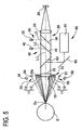
- FIG. 5 is a schematic configuration view of a measurement system and an optical system in a concrete example in the case where the measurement optical system is provided in addition to the intraocular pressure measurement system.
- the components assigned with the same reference signs as those in FIG. 1 have the same functions and configurations as those in FIG. 1 unless particular explanation.
- the intraocular pressure measurement is performed by the same configuration as mentioned above and thus the explanation thereof is not repeated here.
- a measurement optical system 60 includes a measurement optical unit 61 having a structure to project measurement light onto the eye E and receive reflection light therefrom, a total reflection mirror 62, a beam splitter 63 (e.g., a half mirror and a dichroic mirror) that transmits anterior segment observation light and reflects measurement light, and an objective lens 22.
- the fixation target projecting optical system 30 is preferably a known structure capable of fogging a fixation target.
- Measurement light emitted from a measurement light source of the measurement optical unit 61 is reflected by the mirror 62 and the beam splitter 63, then passes through the objective lens 22 and enters the eye E.
- the measurement light reflected by a predetermined portion of the eye E such as the fundus, the cornea, and other passes through the objective lens 22, is reflected by the beam splitter 63 and the mirror 62, and received by a light receiving element, an imaging element, and others in the measurement optical unit 61.
- the arithmetic controller 70 performs a test (e.g., measurement of eye characteristics, acquisition of an image of an examinee's eye, etc.) on the eye E based on a light receiving result (an imaging result).
- a complex type ophthalmic device including the intraocular pressure measurement system and the measurement optical system can be made very compact as compared with a conventional device.
- the device is not limited to the above configuration.
- a projecting optical system for projecting a target onto the cornea Ec to measure corneal curvature e.g., a ring target and a Placido target
- a target image projected on the cornea Ec is imaged by the observation optical system 20 (the imaging element 26) to measure the corneal curvature.
- the target projecting optical system for measuring the corneal curvature is placed without interfering with the transmitting and receiving part 11.
- the device may additionally include a light projecting optical system adapted to project slit light onto an anterior segment of the eye E through the aperture 15 and an imaging optical system having an imaging optical axis intersecting with the observation optical axis (the measurement optical axis) L1 at a predetermined angle and being adapted to receive reflection light from the anterior segment and image a cross-sectional image of the anterior segment, in order to measure corneal thickness, anterior chamber depth, and others based on the cross-sectional image of the imaged anterior segment.
- the imaging optical system is placed without interfering with the transmitting and receiving part 11.
- the device may include an illumination optical system having an illumination optical axis intersecting with the observation optical axis L1 at a predetermined angle and being adapted to obliquely illuminate illumination light to the cornea Ec and an imaging optical system having an imaging optical axis intersecting with the observation optical axis L1 at a predetermined angle and being adapted to receive reflection light from the cornea Ec and image a corneal endothelial cell image, in order to image the corneal endothelial cell image.
- the illumination optical system and the imaging optical system are placed without interfering with the transmitting and receiving part 11.
- the present invention is not limited to the configuration for measuring intraocular pressure by use of the transducer 10 and may be applied to any configuration for measuring internal pressure of an object to be examined (not limited to a living body) by use of the transducer 10. Furthermore, the invention may be applied to any configuration for measuring the characteristics of the object (e.g., stress distribution, shape) by use of the transducer 10.
- the device is provided with the observation unit for observing the object from front in a non-contact manner (e.g., an optical observation unit, an X-ray observation unit, an ultrasound observation unit, and an acoustic observation unit) and the transducer (a first unit) including the aperture having a sufficient size for observation of the object by the observation unit (see FIG. 1 ).
- the object is observed with the observation unit through the aperture 15 of the transducer 10.
- the central axis of the observation unit and the central axis of the transmitting and receiving part 11 are placed in an almost coaxial relation.
- the aperture 15 of the transducer 10 is used to measure the second characteristic of the eye E.
- the invention may also be applied to any configuration utilizing the aperture 15 of the transducer 10 to measure the second characteristic of the object.
- the device includes a second measurement unit 100 (e.g., an optical measurement unit, an X-ray measurement unit, an ultrasound measurement unit, an acoustic measurement unit) for measuring the second characteristic of an object S from front in a non-contact manner, and the transducer (the first unit) including the aperture 15 having a sufficient size for measuring the object S by the measurement unit 100 (see FIG. 6 ).
- the second characteristic of the object S is measured by the measurement unit 100 through the aperture 15 of the transducer 10.
- the central axis of the measurement unit 100 and the central axis of the transmitting and receiving part 11 are preferably placed in an almost coaxial relation.
- the measurement unit 100 emits and/or detects a measurement wave to measure the second characteristic of the object S.
- the measurement wave may be selected according to measurement purposes from an electromagnetic wave (electric wave, light, X-rays, gamma rays, etc.), a sonic wave (ultrasonic wave, acoustic energy), and others.
- a first ultrasound measurement system including the transducer having the aperture and the second measurement system are separately arranged and respective measurements are optimized.
- the present invention is not limited to a configuration to be used in air but may be applied to any configuration to be used in gases.
- the invention is used in gases containing air under atmosphere pressure or in any gases (including inert gas) under arbitrary pressure.
Description
- The present invention relates to a non-contact ultrasound measurement device for measuring characteristics of an object to be examined non-contactively by use of ultrasonic waves.
- As one of non-contact ultrasound measurement devices, there is recently proposed a non-contact ultrasound tonometer including a transducer having a vibrator for emitting an ultrasonic wave toward a cornea of an examinee's eye and a sensor for detecting the ultrasonic wave reflected by the cornea to measure intraocular pressure of the eye in a non-contact manner (see Patent Literature 1).
-
US 5 865 742 A (Patent Literature 2) forms the closest prior art document. It describes how a beam of acoustic energy comprising acoustic radiation and the associated acoustic streaming of an ultrasonic beam is used to indent or applanate (flatten) the eye. These two effects produce acoustic pressure on the eye which partially overcomes the IOP of the eye. Such concurrent determination of acoustic pressure and distortion of the eye is then used to determine the IOP. - Patent Literature 1:
WO 2008/072527 - Patent Literature 2 :
US 5 865 135 A . - Meanwhile, the ultrasound measurement device mentioned above is preferably arranged to enable good observation of the object located in a position away from the device. The ultrasound measurement device is further preferably arranged to enable good measurement of various data on the object.
- For instance, the device in Patent Literature 1 is designed to merely measure a schematic eye. Thus such device is still insufficient to measure a real human eye and has many problems to be solved for practical use. To mitigate fear of an examinee, for example, it is necessary a certain degree of a working distance (e.g., about 10 mm) between the cornea and the device. It is also preferable to satisfactorily observe a state of the eye held in a position away from the device. Furthermore, this device could not measure second eye characteristic different from the intraocular pressure.
- The present invention has a purpose to provide a non-contact ultrasound measurement device capable of accurately measuring a first characteristic of an object to be examined and appropriately observing the object or measuring a second characteristic of the object.
- To achieve the above purposed, the present invention provides a non-contact ultrasound measurement device according to claim 1.
Further developments of the present invention are given in the dependent claims. - According to the invention, it is possible to accurately measure a first characteristic of an object to be examined and appropriately observe the object or measure a second characteristic of the object.
-
-
FIG. 1 is a schematic configuration view of a measurement system and an optical system of a non-contact ultrasound tonometer which is a non-contact ultrasound measurement device in an embodiment; -
FIG. 2 is a schematic configuration view of a transducer seen from front in the embodiment; -
FIG. 3 is a schematic block diagram of a control system of the device in the embodiment. -
FIGs. 4A and 4B are views showing modified examples of the shape of a cross section of a transmitting and receiving part in the embodiment; -
FIG. 5 is a schematic configuration view of a measurement system and an optical system in a concrete example in which an measuring optical system is provided in addition to an intraocular pressure measuring system; and -
FIG. 6 is a view showing an example of a configuration in which an aperture of the transducer is used for measurement of a second characteristic of an object to be examined. - A detailed description of a preferred embodiment of the present invention will now be given referring to the accompanying drawings.
FIG. 1 is a schematic configuration view of a measurement system and an optical system of a non-contact ultrasound tonometer which is a non-contact ultrasound measurement device in this embodiment. The following measurement system and optical system are built in a housing not shown. This housing may be moved three-dimensionally relative to an examinee's eye by a known movement mechanism for alignment or may be a handheld type (handy type). - An
ultrasound transducer 10 emits an ultrasonic wave (a pulse wave or a continuous wave) toward a cornea Ec of the examinee's eye E by the medium of air and also detects the ultrasonic wave reflected by the cornea Ec. Thetransducer 10 includes, as a transmitting and receivingpart 11 of ultrasonic wave, a transmittingsection 12 for emitting an ultrasonic wave and a receivingsection 13 for detecting a reflection wave from the cornea Ec. Thetransducer 10 is used for measuring intraocular pressure in a non-contact manner. In thetransducer 10, the transmittingsection 12 and the receivingsection 13 are separately configured and placed in different positions, but they are not limited to such configuration and may be shared. - The optical system of the device includes an observation
optical system 20 for observing an anterior segment of the eye E from front, a fixation target projecting (presenting)optical system 30 for inducing the eye E to hold fixation, a first target projectingoptical system 40 for projecting a first target onto the cornea Ec to detect an alignment state in up-down and right-left directions, a second target projectingoptical system 50 for projecting a second target onto the cornea Ec to detect an alignment state in a working distance which is a front-rear direction, and a target detectingoptical system 55 for detecting the second target projected onto the cornea Ec. - The observation
optical system 20 includes anobjective lens 22, animage forming lens 24, and a two-dimensionally imaging element 26. Thisoptical system 20 is placed so that its optical axis (an observation optical axis) L1 is almost coaxial with a central axis of the transmitting and receivingpart 11. Accordingly, when the observation optical axis L1 is aligned with respect to a predetermined portion (e.g., the center of a cornea, the center of a pupil) of the eye E, thetransducer 10 is aligned in up-down and right-left directions relative to the eye E. - An image of the anterior segment illuminated by an
infrared light source 38 passes through anaperture 15, theobjective lens 22, ahalf mirror 46, and adichroic mirror 36 in order and then forms an image on theimaging element 26 through theimage forming lens 24. The anterior segment image imaged by theimaging element 26 is displayed on amonitor 72 mentioned later. - The fixation target projecting
optical system 30 includes avisible light source 32 to project a fixation target onto the eye E to induce the eye E to hold fixation. Visible light from thelight source 32 is reflected by thedichroic mirror 36 that transmits infrared light but reflects visible light. This light then passes through thehalf mirror 46 and theobjective lens 22 and is projected onto a fundus of the eye E. An optical axis L2 of the fixation target projectingoptical system 30 is made coaxial with the observation optical axis L1 by thedichroic mirror 36 placed in the optical path (the observation optical path) of the observationoptical system 20. - The first target projecting
optical system 40 includes aninfrared light source 42 and projects infrared light onto the cornea Ec from front so that the infrared light forms the first target for detecting the alignment state in the up-down and right-left directions. The infrared light from thelight source 42 is reflected by thehalf mirror 46, passes through theobjective lens 22, and is projected onto the cornea Ec. An optical axis L3 of the first target projectingoptical system 40 is made coaxial with the observation optical axis L1 by thehalf mirror 46 placed in the observation optical path (the optical path of the observation light). - The observation
optical system 20 detects the first target formed on the cornea Ec (i.e., theoptical system 20 receives the infrared light that is emitted from thelight source 42 and reflected by the cornea Ec) by the first target projectingoptical system 40. In other words, the observationoptical system 20 is also used as a target detecting optical system. The first target image imaged by theimaging element 26 is displayed on the monitor 72 (see a point image I inFIG. 3 ). - The second target projecting
optical system 50 includes aninfrared light source 51 and obliquely projects infrared light onto the cornea Ec so that the infrared light forms a second target for detecting an alignment state in the working distance direction. - The target detecting
optical system 55 includes a position detecting device (e.g., a line CCD) 58 and detects the second target image formed on the cornea Ec by the second target projecting optical system 50 (i.e., theoptical system 55 receives the infrared light that is emitted from thelight source 51 and reflected by the cornea Ec). It is to be noted that detection of the alignment state in the working distance direction may be conducted by thetransducer 10. For example, the time until an ultrasonic wave emitted to the examinee's eye returns to thetransducer 10 is converted into distance. -
FIG. 2 is a schematic configuration view of thetransducer 10 seen from front in the present embodiment. Thetransducer 10 centrally includes theaperture 15 having a sufficient size to be used as an observation optical path and the transmitting and receivingpart 11 is placed to surround theaperture 15. - To be more specific, the
base part 10a is formed with a through hole having an inside diameter corresponding to theaperture 15, and the transmitting and receivingpart 11 is placed on thebase part 10a on a side facing the eye E and in an almost annular form outside the through hole. The transmittingsection 12 and the receivingsection 13 are placed concentrically in different positions. - In
FIG. 2 , the transmittingsection 12 is located outside and the receivingsection 13 is located inside. Alternatively, the receivingsection 13 may be placed outside and the transmittingsection 12 may be inside. - The
objective lens 22 is placed in theaperture 15. It is to be understood that other optical member(s) (e.g., a glass plate, a filter, etc.) may be placed in theaperture 15 or the optical member as mentioned above may not be placed in theaperture 15. - The
aperture 15 has a size enough for observation of the examinee's eye by the observationoptical system 20 to ensure an observation range in a permissible range by the observationoptical system 20. For instance, the size of the aperture 15 (the inside diameter of the through hole of thebase part 10a) is appropriately determined by considering whether or not alignment with respect to the examinee's eye is smoothly performed, whether or not a state of the anterior segment is observed well, or others. The shape of theaperture 15 is not limited to a perfect circle and may be any other shape (e.g., rectangular, elliptic, and others). - The transmitting and receiving
part 11 is preferably an air-coupled ultrasound transmitting and receiving part (an ultrasound transducer) for transmitting and receiving an ultrasonic wave having a broadband frequency component in order to enhance propagation efficiency in air. In this case, a BAT™ transducer manufactured by MicroAcoustic Instrument Inc. is available. For the details of such transducer, seeUS 5,287,331 andJP-A-2005-506783 -
FIG. 3 is a schematic block diagram of a control system of the device in the present embodiment. Anarithmetic controller 70 performs control of the entire device. Thiscontroller 70 processes an output signal from thetransducer 10 and determines intraocular pressure of the eye E. The transducer 10 (the transmitting and receiving part 11) is connected to theamplifier 81. Thus, an electric signal output from thetransducer 10 is amplified by theamplifier 81 and transmitted to thecontroller 70. Thecontroller 70 is also connected to theimaging element 26, thelight sources position detecting device 58, themonitor 72, thememory 75, and others. Thememory 75 stores in advance a measurement program for measuring the intraocular pressure by use of thetransducer 10, a control program for controlling the entire device, and other programs. - The case of measuring the intraocular pressure of the eye E by the device having the above configuration is explained below. An examiner firstly induces an examinee to look at a fixation target. While observing the anterior segment image appearing on the
monitor 72, the examiner makes alignment of thetransducer 10 with respect to the eye E. At that time, thearithmetic controller 70 displays the anterior segment image imaged by theimaging element 26 including a first target image I, and a reticule LT and an indicator G mentioned later, on the monitor 71 as shown inFIG. 3 . Thecontroller 70 detects an alignment state in the working distance direction based on an output signal from theposition detecting device 58 and controls the display of the indicator G based on the detection result. - The examiner makes alignment of the device in the up-down and right-left directions to bring the first target image I into the reticule LT. The examiner further makes alignment in the working distance direction so that the indicator G appears in an appropriate display state (for example, the indicator appears as a single line).
- After completion of alignment in the up-down, right-left, and front-back directions, when a predetermined trigger signal is manually or automatically input, the
arithmetic controller 70 causes the transmittingsection 12 to emit the ultrasonic wave toward the center of the cornea Ec and causes the receivingsection 13 to detect the ultrasonic wave reflected by the cornea Ec. Thecontroller 70 determines the intraocular pressure of the eye E based on the detection result by the transmitting and receivingpart 11 and displays the result on themonitor 72. Specifically, thecontroller 70 obtains an intraocular pressure value based on a relationship between amplitude of the ultrasonic wave detected by the transmitting and receivingpart 11 and intraocular pressure. For instance, the intraocular pressure is calculated by utilizing the tendency that an amplitude level of the reflection wave is larger as the intraocular pressure value is larger. - As described above, the transmitting and receiving
part 11 is placed outside the observation optical path and hence the areas of the transmittingsection 12 and the receivingsection 13 are ensured and the observation optical path is not interrupted. Since the transmitting and receivingpart 11 is placed to surround theaperture 15, it is possible to increase an S/N ratio of a detection signal of the reflection wave from the cornea Ec detected by thetransducer 10 even when the working distance from the eye E is increased. - In other words, the region for observation of the anterior segment is appropriately placed in the central portion and the region for transmission and reception of the ultrasonic wave is appropriately placed in a peripheral portion relative to the cornea. Accordingly, the
transducer 10 and the observationoptical system 20 are optimized to enable appropriate measurement of intraocular pressure and observation of the anterior segment by transmission and reception of the ultrasonic wave. - Since the transmitting and receiving part 11 (the transmitting
section 12 and the receiving section 13) is designed to be almost annular, an incident wave to the cornea Ec is almost uniform and thus the reflection wave from the cornea Ec can be precisely detected. - A cross-sectional shape of the transmitting and receiving
part 11 on the eye E side is not limited to the flat shape as shown inFIG. 1 but may be conical (or tapered) as shown inFIG. 4A or spherical as shown inFIG. 4B . - The transmitting
section 12 and the receivingsection 13 are not limited to the double ring structure shown inFIG. 2 but may be configured as a triple or more ring structure. In other words, at least one of the transmittingsection 12 and the receivingsection 13 may be configured as a double or more ring structure. - The transmitting and receiving
part 11 is not limited to a configuration surrounding almost theentire aperture 15 as shown inFIG. 2 but may be designed to surround a part of the circumstance of theaperture 15. In the case where the transmitting and receivingpart 11 is placed in almost annular form, accordingly, it may be arranged in an intermittent circular form instead of a continuous circular form. - The shape of the transmitting and receiving
part 11 is preferably almost annular but may be variously modified. For instance, it may be polygonal (a polygon having the larger number of sides is more preferable). - In addition to the configuration for measuring the intraocular pressure with the ultrasonic wave by use of the transducer 10 (the transmitting and receiving part 11), a measuring optical system may be provided to measure a second characteristic of the eye E different from the intraocular pressure. In this case, the
aperture 15 is used as a measuring optical path (an optical path of measurement light). Theaperture 15 is also designed to have a sufficient size to measure the examinee's eye by the measurement optical system in order to ensure permissible measurement precision. The measurement optical system may include for example an eye refractive power measurement optical system adapted to project measurement light onto the fundus of the eye E and receive reflection light therefrom to measure eye refractive power, a corneal shape measurement optical system adapted to project measurement light onto the cornea Ec and receive reflection light therefrom to measure a corneal shape, an eye axial length measurement optical system adapted to receive interference light by measurement light and reference light, and others to measure an axial length. -
FIG. 5 is a schematic configuration view of a measurement system and an optical system in a concrete example in the case where the measurement optical system is provided in addition to the intraocular pressure measurement system. The components assigned with the same reference signs as those inFIG. 1 have the same functions and configurations as those inFIG. 1 unless particular explanation. The intraocular pressure measurement is performed by the same configuration as mentioned above and thus the explanation thereof is not repeated here. - A measurement
optical system 60 includes a measurementoptical unit 61 having a structure to project measurement light onto the eye E and receive reflection light therefrom, atotal reflection mirror 62, a beam splitter 63 (e.g., a half mirror and a dichroic mirror) that transmits anterior segment observation light and reflects measurement light, and anobjective lens 22. In the case where the eye refractive power measurement unit is provided as the measurementoptical unit 61, the fixation target projectingoptical system 30 is preferably a known structure capable of fogging a fixation target. - Measurement light emitted from a measurement light source of the measurement
optical unit 61 is reflected by themirror 62 and thebeam splitter 63, then passes through theobjective lens 22 and enters the eye E. The measurement light reflected by a predetermined portion of the eye E such as the fundus, the cornea, and other passes through theobjective lens 22, is reflected by thebeam splitter 63 and themirror 62, and received by a light receiving element, an imaging element, and others in the measurementoptical unit 61. Thearithmetic controller 70 performs a test (e.g., measurement of eye characteristics, acquisition of an image of an examinee's eye, etc.) on the eye E based on a light receiving result (an imaging result). - With such configuration, a complex type ophthalmic device including the intraocular pressure measurement system and the measurement optical system can be made very compact as compared with a conventional device.
- The device is not limited to the above configuration. For example, a projecting optical system for projecting a target onto the cornea Ec to measure corneal curvature (e.g., a ring target and a Placido target) is further provided so that a target image projected on the cornea Ec is imaged by the observation optical system 20 (the imaging element 26) to measure the corneal curvature. In this case, the target projecting optical system for measuring the corneal curvature is placed without interfering with the transmitting and receiving
part 11. - Furthermore, the device may additionally include a light projecting optical system adapted to project slit light onto an anterior segment of the eye E through the
aperture 15 and an imaging optical system having an imaging optical axis intersecting with the observation optical axis (the measurement optical axis) L1 at a predetermined angle and being adapted to receive reflection light from the anterior segment and image a cross-sectional image of the anterior segment, in order to measure corneal thickness, anterior chamber depth, and others based on the cross-sectional image of the imaged anterior segment. In this case, the imaging optical system is placed without interfering with the transmitting and receivingpart 11. - As another alternative, the device may include an illumination optical system having an illumination optical axis intersecting with the observation optical axis L1 at a predetermined angle and being adapted to obliquely illuminate illumination light to the cornea Ec and an imaging optical system having an imaging optical axis intersecting with the observation optical axis L1 at a predetermined angle and being adapted to receive reflection light from the cornea Ec and image a corneal endothelial cell image, in order to image the corneal endothelial cell image. In this case, the illumination optical system and the imaging optical system are placed without interfering with the transmitting and receiving
part 11. - The present invention is not limited to the configuration for measuring intraocular pressure by use of the
transducer 10 and may be applied to any configuration for measuring internal pressure of an object to be examined (not limited to a living body) by use of thetransducer 10. Furthermore, the invention may be applied to any configuration for measuring the characteristics of the object (e.g., stress distribution, shape) by use of thetransducer 10. - In the above case, the device is provided with the observation unit for observing the object from front in a non-contact manner (e.g., an optical observation unit, an X-ray observation unit, an ultrasound observation unit, and an acoustic observation unit) and the transducer (a first unit) including the aperture having a sufficient size for observation of the object by the observation unit (see
FIG. 1 ). In this case, the object is observed with the observation unit through theaperture 15 of thetransducer 10. Preferably, the central axis of the observation unit and the central axis of the transmitting and receivingpart 11 are placed in an almost coaxial relation. - In the above explanation, the
aperture 15 of thetransducer 10 is used to measure the second characteristic of the eye E. The invention may also be applied to any configuration utilizing theaperture 15 of thetransducer 10 to measure the second characteristic of the object. - In the above case, the device includes a second measurement unit 100 (e.g., an optical measurement unit, an X-ray measurement unit, an ultrasound measurement unit, an acoustic measurement unit) for measuring the second characteristic of an object S from front in a non-contact manner, and the transducer (the first unit) including the
aperture 15 having a sufficient size for measuring the object S by the measurement unit 100 (seeFIG. 6 ). In this case, the second characteristic of the object S is measured by themeasurement unit 100 through theaperture 15 of thetransducer 10. The central axis of themeasurement unit 100 and the central axis of the transmitting and receivingpart 11 are preferably placed in an almost coaxial relation. - Specifically, the
measurement unit 100 emits and/or detects a measurement wave to measure the second characteristic of the object S. The measurement wave may be selected according to measurement purposes from an electromagnetic wave (electric wave, light, X-rays, gamma rays, etc.), a sonic wave (ultrasonic wave, acoustic energy), and others. - With the above structure, a first ultrasound measurement system including the transducer having the aperture and the second measurement system are separately arranged and respective measurements are optimized.
- The present invention is not limited to a configuration to be used in air but may be applied to any configuration to be used in gases. For instance, it is conceived that the invention is used in gases containing air under atmosphere pressure or in any gases (including inert gas) under arbitrary pressure.
- While the presently preferred embodiment of the present invention has been shown and described, it is to be understood that this disclosure is for the purpose of illumination and that various changes and modifications may be made without departing from the scope of the invention as set forth in the appended claims.
-
- 10
- Ultrasound transducer
- 11
- Transmitting and receiving part
- 12
- Transmitting section
- 13
- Receiving section
- 15
- Aperture
- 20
- Observation optical system
- 50
- Second target projecting optical system
- 55
- Target detecting optical system
- 60
- Measurement optical system
- 100
- Second measurement unit
Claims (10)
- A non-contact ultrasound measurement device comprising:a first unit (10, 70) including an ultrasound transducer (10) adapted to transmit and receive an ultrasonic wave in a non-contact manner with respect to an object to be examined (E, S), the first unit being adapted to process an output signal from the transducer and measure a first characteristic of the object, the first characteristic being internal pressure of the object; anda second unit (20, 60, 70, 100) including at least one of an observation unit (20) for observing the object from front in a non-contact manner and a measurement unit (60, 100) for measuring a second characteristic of the object from front in a non-contact manner,wherein the transducer comprises:an aperture (15) being provided in the central part of the transducer and having a sufficient size to be utilized for observation or measurement of the object by the second unit, anda transmitting and receiving part (11) of the ultrasonic wave being provided to surround the aperture,whereinthe transmitting and receiving part (11) includes a transmitting section (12) for emitting an ultrasonic beam toward the object, and a receiving section (13) for detecting the ultrasonic beam reflected by the object, andcharacterized in that the first unit is configured to obtain internal pressure of the object based on a relationship between the amplitude of the ultrasonic beam detected by the receiving section and the internal pressure of the object.
- The non-contact ultrasound measurement device according to claim 1, wherein the observation unit or the measurement unit includes at least one of an optical unit, an X-ray unit, an ultrasound unit, and an acoustic unit.
- The non-contact ultrasound measurement device according to one of claims 1 to 2, wherein the observation unit includes an objective lens (22) to be placed before the object, and the objective lens is placed in the aperture.
- The non-contact ultrasound measurement device according to one of claims 1 to 3, wherein the ultrasound transducer is a broadband air-coupled transducer for transmitting and receiving the ultrasonic wave having a broad band frequency component.
- The non-contact ultrasound measurement device according to one of claims 1 to 4, wherein the transmitting and receiving part is placed in an almost annular form outside the aperture.
- The non-contact ultrasound measurement device according to one of claims 1 to 5, wherein a transmitting section and a receiving section of the transmitting and receiving part are arranged concentrically in different positions.
- The non-contact ultrasound measurement device according to one of claims 1 to 6, wherein
the object is an examinee's eye,
the first characteristic is intraocular pressure which is a first eye characteristic of the examinee's eye, and
the observation unit is an observation optical system adapted to observe an anterior segment of the examinee's eye from front. - The non-contact ultrasound measurement device according to claim 7, wherein
the transmitting section is adapted to transmit an ultrasound pulse wave toward the center of a cornea of the examinee's eye and the receiving section is adapted to receive the ultrasound pulse wave reflected by the center of the cornea, and
the first measurement unit obtains an intraocular pressure value based on a relationship between wave characteristics of the reflected ultrasound pulse wave detected by the receiving section and the intraocular pressure. - The non-contact ultrasound measurement device according to claim 7 or 8, wherein
the measurement unit is a measurement optical system adapted to measure a second eye characteristic of the examinee's eye as the second characteristic from front, and the aperture surrounded by the transmitting and receiving part is used as a measurement optical path of the measurement optical system. - The non-contact ultrasound measurement device according to claim 9, wherein the measurement optical system includes at least one of an eye refractive power measurement optical system adapted to project measurement light onto a fundus of the examinee's eye and receive reflection light from the fundus to measure eye refractive power of the examinee's eye as the second eye characteristic and a corneal shape measurement optical system adapted to project measurement light onto a cornea of the examinee's eye and receive reflection light from the cornea to measure a shape of the cornea as the second eye characteristic.
Applications Claiming Priority (1)
| Application Number | Priority Date | Filing Date | Title |
|---|---|---|---|
| JP2009138620A JP5469381B2 (en) | 2009-06-09 | 2009-06-09 | Non-contact ultrasonic measurement device |
Publications (2)
| Publication Number | Publication Date |
|---|---|
| EP2260765A1 EP2260765A1 (en) | 2010-12-15 |
| EP2260765B1 true EP2260765B1 (en) | 2013-03-06 |
Family
ID=42333326
Family Applications (1)
| Application Number | Title | Priority Date | Filing Date |
|---|---|---|---|
| EP10165412A Not-in-force EP2260765B1 (en) | 2009-06-09 | 2010-06-09 | Non-contact ultrasonic measurement device |
Country Status (4)
| Country | Link |
|---|---|
| US (1) | US20100312087A1 (en) |
| EP (1) | EP2260765B1 (en) |
| JP (1) | JP5469381B2 (en) |
| CA (1) | CA2707193A1 (en) |
Families Citing this family (3)
| Publication number | Priority date | Publication date | Assignee | Title |
|---|---|---|---|---|
| JP5562703B2 (en) * | 2010-03-31 | 2014-07-30 | 株式会社ニデック | Non-contact ultrasonic tonometer |
| US20210068656A1 (en) * | 2018-03-30 | 2021-03-11 | Nidek Co., Ltd. | Non-contact ultrasonic ophthalmotonometer |
| JP7259599B2 (en) * | 2019-07-03 | 2023-04-18 | 株式会社ニデック | ultrasonic tonometer |
Family Cites Families (25)
| Publication number | Priority date | Publication date | Assignee | Title |
|---|---|---|---|---|
| US4764006A (en) * | 1985-09-13 | 1988-08-16 | Canon Kabushiki Kaisha | Ophthalmic measuring apparatus |
| US5325135A (en) * | 1987-03-06 | 1994-06-28 | Canon Kabushiki Kaisha | Ophthalmologic apparatus having two measuring systems |
| US5183044A (en) * | 1987-06-30 | 1993-02-02 | Kabushiki Kaisha Topcon | Noncontact type tonometer |
| US4928697A (en) * | 1988-09-28 | 1990-05-29 | The Ohio State University | Non-contact high frequency tonometer |
| JP2778153B2 (en) * | 1989-09-28 | 1998-07-23 | 株式会社島津製作所 | Ultrasonic probe |
| US6234966B1 (en) * | 1991-08-31 | 2001-05-22 | Nidek Co., Ltd. | Noncontact type tonometer |
| JPH05253190A (en) * | 1991-10-10 | 1993-10-05 | Massie Res Lab Inc | Non-contact type tonometer |
| US5287331A (en) * | 1992-10-26 | 1994-02-15 | Queen's University | Air coupled ultrasonic transducer |
| GB9308286D0 (en) * | 1993-04-22 | 1993-06-09 | Toleman Paul | Tonometer |
| CA2169307C (en) * | 1994-12-12 | 2003-10-14 | David A. Hutchins | Non-contact characterization and inspection of materials using wideband air coupled ultrasound |
| JP3461957B2 (en) * | 1995-02-28 | 2003-10-27 | 株式会社ニデック | Ophthalmic equipment |
| US5865742A (en) * | 1995-03-06 | 1999-02-02 | Massie Research Laboratories, Inc. | Non-contact tonometer |
| AU2285197A (en) * | 1996-04-18 | 1997-11-12 | Ramseier, Hans-Ulrich | Characterisation of objects by means of ultrasonic waves |
| US6339961B1 (en) * | 1996-11-15 | 2002-01-22 | Ue Systems, Inc. | Ultrasonic detecting lubrication apparatus with acoustically isolated transducer |
| US6030343A (en) * | 1997-09-03 | 2000-02-29 | Pgvc Lp | Single beam tone burst ultrasonic non contact tonometer and method of measuring intraocular pressure |
| US6494577B2 (en) * | 2000-03-17 | 2002-12-17 | Canon Kabushiki Kaisha | Ophthalmologic apparatus |
| JP3693561B2 (en) * | 2000-07-26 | 2005-09-07 | 株式会社ニデック | Non-contact tonometer |
| US7101335B2 (en) * | 2001-02-01 | 2006-09-05 | Nidek Co., Ltd. | Non-contact type tonometer |
| US6673014B2 (en) * | 2001-10-05 | 2004-01-06 | Itonix, Inc. | Noninvasive methods and apparatuses for measuring the intraocular pressure of a mammal eye |
| EP1446238B1 (en) * | 2001-10-23 | 2012-06-20 | SCHINDEL, David W. | Ultrasonic printed circuit board transducer |
| DE102006033035B4 (en) * | 2006-07-14 | 2015-06-03 | Universität Bremen | Apparatus and method for contactless internal pressure determination |
| WO2008072527A1 (en) | 2006-12-08 | 2008-06-19 | Nihon University | Intraocular pressure measuring device |
| JP5172141B2 (en) * | 2006-12-26 | 2013-03-27 | 株式会社ニデック | Axial length measuring device |
| US8092018B2 (en) * | 2008-05-03 | 2012-01-10 | Nidek Co., Ltd. | Non-contact ultrasonic tonometer |
| JP5396633B2 (en) * | 2008-05-03 | 2014-01-22 | 株式会社ニデック | Non-contact ultrasonic tonometer |
-
2009
- 2009-06-09 JP JP2009138620A patent/JP5469381B2/en not_active Expired - Fee Related
-
2010
- 2010-06-07 US US12/795,061 patent/US20100312087A1/en not_active Abandoned
- 2010-06-08 CA CA2707193A patent/CA2707193A1/en not_active Abandoned
- 2010-06-09 EP EP10165412A patent/EP2260765B1/en not_active Not-in-force
Also Published As
| Publication number | Publication date |
|---|---|
| US20100312087A1 (en) | 2010-12-09 |
| JP2010284223A (en) | 2010-12-24 |
| EP2260765A1 (en) | 2010-12-15 |
| JP5469381B2 (en) | 2014-04-16 |
| CA2707193A1 (en) | 2010-12-09 |
Similar Documents
| Publication | Publication Date | Title |
|---|---|---|
| US11659994B2 (en) | Method and arrangement for eye pressure measurements | |
| EP2113192B1 (en) | Non-contact ultrasonic tonometer | |
| EP2266454A1 (en) | Non-contact ultrasonic tonometer | |
| EP2236075B1 (en) | Non-contact ultrasonic tonometer | |
| USRE45013E1 (en) | Non-contact ultrasonic tonometer | |
| JP5410692B2 (en) | Non-contact ultrasonic tonometer | |
| US20070123769A1 (en) | Tonometer-pachymeter apparatus for measurement of intraocular pressure | |
| JP2009254779A (en) | Ophthalmological ultrasonic diagnostic system | |
| JP5397670B2 (en) | Non-contact ultrasonic tonometer | |
| EP2260765B1 (en) | Non-contact ultrasonic measurement device | |
| US9232892B2 (en) | Applanation tonometer and method for measuring the intraocular pressure of the eye | |
| JP2015085042A (en) | Non-contact ultrasonic tonometer | |
| JP2011045602A (en) | Non-contact ultrasonic tonometer | |
| JP5465946B2 (en) | Non-contact ultrasonic tonometer | |
| JP5562703B2 (en) | Non-contact ultrasonic tonometer | |
| JP5117275B2 (en) | Non-contact ultrasonic tonometer | |
| JP5601622B2 (en) | Non-contact ultrasonic tonometer | |
| JP7375321B2 (en) | intraocular pressure measuring device | |
| JP5410923B2 (en) | Non-contact ultrasonic tonometer | |
| JPH01242045A (en) | Ophthalmic ultrasonic examination apparatus | |
| JPH0191832A (en) | Ophthalmic measuring apparatus | |
| JP2010240486A (en) | Ophthalmologic examination apparatus |
Legal Events
| Date | Code | Title | Description |
|---|---|---|---|
| PUAI | Public reference made under article 153(3) epc to a published international application that has entered the european phase |
Free format text: ORIGINAL CODE: 0009012 |
|
| AK | Designated contracting states |
Kind code of ref document: A1 Designated state(s): AL AT BE BG CH CY CZ DE DK EE ES FI FR GB GR HR HU IE IS IT LI LT LU LV MC MK MT NL NO PL PT RO SE SI SK SM TR |
|
| AX | Request for extension of the european patent |
Extension state: BA ME RS |
|
| 17P | Request for examination filed |
Effective date: 20110608 |
|
| RIN1 | Information on inventor provided before grant (corrected) |
Inventor name: MIWA, TETSUYUKI Inventor name: JINDE, MASAYUKI Inventor name: SCHINDEL, DAVID W. |
|
| RAP1 | Party data changed (applicant data changed or rights of an application transferred) |
Owner name: NIDEK CO., LTD Owner name: MICROACOUSTIC INSTRUMENTS INC. |
|
| 17Q | First examination report despatched |
Effective date: 20110829 |
|
| RIC1 | Information provided on ipc code assigned before grant |
Ipc: A61B 3/107 20060101ALN20120801BHEP Ipc: A61B 3/103 20060101ALN20120801BHEP Ipc: A61B 3/16 20060101ALI20120801BHEP Ipc: A61B 8/10 20060101AFI20120801BHEP |
|
| GRAP | Despatch of communication of intention to grant a patent |
Free format text: ORIGINAL CODE: EPIDOSNIGR1 |
|
| GRAS | Grant fee paid |
Free format text: ORIGINAL CODE: EPIDOSNIGR3 |
|
| GRAA | (expected) grant |
Free format text: ORIGINAL CODE: 0009210 |
|
| AK | Designated contracting states |
Kind code of ref document: B1 Designated state(s): AL AT BE BG CH CY CZ DE DK EE ES FI FR GB GR HR HU IE IS IT LI LT LU LV MC MK MT NL NO PL PT RO SE SI SK SM TR |
|
| REG | Reference to a national code |
Ref country code: GB Ref legal event code: FG4D |
|
| REG | Reference to a national code |
Ref country code: AT Ref legal event code: REF Ref document number: 599153 Country of ref document: AT Kind code of ref document: T Effective date: 20130315 Ref country code: CH Ref legal event code: EP |
|
| REG | Reference to a national code |
Ref country code: IE Ref legal event code: FG4D |
|
| REG | Reference to a national code |
Ref country code: DE Ref legal event code: R096 Ref document number: 602010005193 Country of ref document: DE Effective date: 20130425 |
|
| REG | Reference to a national code |
Ref country code: AT Ref legal event code: MK05 Ref document number: 599153 Country of ref document: AT Kind code of ref document: T Effective date: 20130306 |
|
| PG25 | Lapsed in a contracting state [announced via postgrant information from national office to epo] |
Ref country code: AT Free format text: LAPSE BECAUSE OF FAILURE TO SUBMIT A TRANSLATION OF THE DESCRIPTION OR TO PAY THE FEE WITHIN THE PRESCRIBED TIME-LIMIT Effective date: 20130306 Ref country code: SE Free format text: LAPSE BECAUSE OF FAILURE TO SUBMIT A TRANSLATION OF THE DESCRIPTION OR TO PAY THE FEE WITHIN THE PRESCRIBED TIME-LIMIT Effective date: 20130306 Ref country code: ES Free format text: LAPSE BECAUSE OF FAILURE TO SUBMIT A TRANSLATION OF THE DESCRIPTION OR TO PAY THE FEE WITHIN THE PRESCRIBED TIME-LIMIT Effective date: 20130617 Ref country code: BG Free format text: LAPSE BECAUSE OF FAILURE TO SUBMIT A TRANSLATION OF THE DESCRIPTION OR TO PAY THE FEE WITHIN THE PRESCRIBED TIME-LIMIT Effective date: 20130606 Ref country code: NO Free format text: LAPSE BECAUSE OF FAILURE TO SUBMIT A TRANSLATION OF THE DESCRIPTION OR TO PAY THE FEE WITHIN THE PRESCRIBED TIME-LIMIT Effective date: 20130606 Ref country code: LT Free format text: LAPSE BECAUSE OF FAILURE TO SUBMIT A TRANSLATION OF THE DESCRIPTION OR TO PAY THE FEE WITHIN THE PRESCRIBED TIME-LIMIT Effective date: 20130306 |
|
| REG | Reference to a national code |
Ref country code: NL Ref legal event code: VDEP Effective date: 20130306 |
|
| REG | Reference to a national code |
Ref country code: LT Ref legal event code: MG4D |
|
| PG25 | Lapsed in a contracting state [announced via postgrant information from national office to epo] |
Ref country code: GR Free format text: LAPSE BECAUSE OF FAILURE TO SUBMIT A TRANSLATION OF THE DESCRIPTION OR TO PAY THE FEE WITHIN THE PRESCRIBED TIME-LIMIT Effective date: 20130607 Ref country code: FI Free format text: LAPSE BECAUSE OF FAILURE TO SUBMIT A TRANSLATION OF THE DESCRIPTION OR TO PAY THE FEE WITHIN THE PRESCRIBED TIME-LIMIT Effective date: 20130306 Ref country code: SI Free format text: LAPSE BECAUSE OF FAILURE TO SUBMIT A TRANSLATION OF THE DESCRIPTION OR TO PAY THE FEE WITHIN THE PRESCRIBED TIME-LIMIT Effective date: 20130306 Ref country code: LV Free format text: LAPSE BECAUSE OF FAILURE TO SUBMIT A TRANSLATION OF THE DESCRIPTION OR TO PAY THE FEE WITHIN THE PRESCRIBED TIME-LIMIT Effective date: 20130306 |
|
| PG25 | Lapsed in a contracting state [announced via postgrant information from national office to epo] |
Ref country code: HR Free format text: LAPSE BECAUSE OF FAILURE TO SUBMIT A TRANSLATION OF THE DESCRIPTION OR TO PAY THE FEE WITHIN THE PRESCRIBED TIME-LIMIT Effective date: 20130306 Ref country code: BE Free format text: LAPSE BECAUSE OF FAILURE TO SUBMIT A TRANSLATION OF THE DESCRIPTION OR TO PAY THE FEE WITHIN THE PRESCRIBED TIME-LIMIT Effective date: 20130306 |
|
| PG25 | Lapsed in a contracting state [announced via postgrant information from national office to epo] |
Ref country code: NL Free format text: LAPSE BECAUSE OF FAILURE TO SUBMIT A TRANSLATION OF THE DESCRIPTION OR TO PAY THE FEE WITHIN THE PRESCRIBED TIME-LIMIT Effective date: 20130306 Ref country code: CZ Free format text: LAPSE BECAUSE OF FAILURE TO SUBMIT A TRANSLATION OF THE DESCRIPTION OR TO PAY THE FEE WITHIN THE PRESCRIBED TIME-LIMIT Effective date: 20130306 Ref country code: IS Free format text: LAPSE BECAUSE OF FAILURE TO SUBMIT A TRANSLATION OF THE DESCRIPTION OR TO PAY THE FEE WITHIN THE PRESCRIBED TIME-LIMIT Effective date: 20130706 Ref country code: EE Free format text: LAPSE BECAUSE OF FAILURE TO SUBMIT A TRANSLATION OF THE DESCRIPTION OR TO PAY THE FEE WITHIN THE PRESCRIBED TIME-LIMIT Effective date: 20130306 Ref country code: RO Free format text: LAPSE BECAUSE OF FAILURE TO SUBMIT A TRANSLATION OF THE DESCRIPTION OR TO PAY THE FEE WITHIN THE PRESCRIBED TIME-LIMIT Effective date: 20130306 Ref country code: SK Free format text: LAPSE BECAUSE OF FAILURE TO SUBMIT A TRANSLATION OF THE DESCRIPTION OR TO PAY THE FEE WITHIN THE PRESCRIBED TIME-LIMIT Effective date: 20130306 Ref country code: PT Free format text: LAPSE BECAUSE OF FAILURE TO SUBMIT A TRANSLATION OF THE DESCRIPTION OR TO PAY THE FEE WITHIN THE PRESCRIBED TIME-LIMIT Effective date: 20130708 |
|
| PG25 | Lapsed in a contracting state [announced via postgrant information from national office to epo] |
Ref country code: PL Free format text: LAPSE BECAUSE OF FAILURE TO SUBMIT A TRANSLATION OF THE DESCRIPTION OR TO PAY THE FEE WITHIN THE PRESCRIBED TIME-LIMIT Effective date: 20130306 |
|
| PLBE | No opposition filed within time limit |
Free format text: ORIGINAL CODE: 0009261 |
|
| STAA | Information on the status of an ep patent application or granted ep patent |
Free format text: STATUS: NO OPPOSITION FILED WITHIN TIME LIMIT |
|
| PG25 | Lapsed in a contracting state [announced via postgrant information from national office to epo] |
Ref country code: MC Free format text: LAPSE BECAUSE OF FAILURE TO SUBMIT A TRANSLATION OF THE DESCRIPTION OR TO PAY THE FEE WITHIN THE PRESCRIBED TIME-LIMIT Effective date: 20130306 Ref country code: DK Free format text: LAPSE BECAUSE OF FAILURE TO SUBMIT A TRANSLATION OF THE DESCRIPTION OR TO PAY THE FEE WITHIN THE PRESCRIBED TIME-LIMIT Effective date: 20130306 |
|
| 26N | No opposition filed |
Effective date: 20131209 |
|
| PG25 | Lapsed in a contracting state [announced via postgrant information from national office to epo] |
Ref country code: IT Free format text: LAPSE BECAUSE OF FAILURE TO SUBMIT A TRANSLATION OF THE DESCRIPTION OR TO PAY THE FEE WITHIN THE PRESCRIBED TIME-LIMIT Effective date: 20130306 |
|
| REG | Reference to a national code |
Ref country code: DE Ref legal event code: R097 Ref document number: 602010005193 Country of ref document: DE Effective date: 20131209 |
|
| REG | Reference to a national code |
Ref country code: IE Ref legal event code: MM4A |
|
| PG25 | Lapsed in a contracting state [announced via postgrant information from national office to epo] |
Ref country code: IE Free format text: LAPSE BECAUSE OF NON-PAYMENT OF DUE FEES Effective date: 20130609 |
|
| REG | Reference to a national code |
Ref country code: CH Ref legal event code: PL |
|
| PG25 | Lapsed in a contracting state [announced via postgrant information from national office to epo] |
Ref country code: MT Free format text: LAPSE BECAUSE OF FAILURE TO SUBMIT A TRANSLATION OF THE DESCRIPTION OR TO PAY THE FEE WITHIN THE PRESCRIBED TIME-LIMIT Effective date: 20130306 |
|
| PG25 | Lapsed in a contracting state [announced via postgrant information from national office to epo] |
Ref country code: LI Free format text: LAPSE BECAUSE OF NON-PAYMENT OF DUE FEES Effective date: 20140630 Ref country code: CH Free format text: LAPSE BECAUSE OF NON-PAYMENT OF DUE FEES Effective date: 20140630 |
|
| PG25 | Lapsed in a contracting state [announced via postgrant information from national office to epo] |
Ref country code: SM Free format text: LAPSE BECAUSE OF FAILURE TO SUBMIT A TRANSLATION OF THE DESCRIPTION OR TO PAY THE FEE WITHIN THE PRESCRIBED TIME-LIMIT Effective date: 20130306 |
|
| PG25 | Lapsed in a contracting state [announced via postgrant information from national office to epo] |
Ref country code: TR Free format text: LAPSE BECAUSE OF FAILURE TO SUBMIT A TRANSLATION OF THE DESCRIPTION OR TO PAY THE FEE WITHIN THE PRESCRIBED TIME-LIMIT Effective date: 20130306 Ref country code: CY Free format text: LAPSE BECAUSE OF FAILURE TO SUBMIT A TRANSLATION OF THE DESCRIPTION OR TO PAY THE FEE WITHIN THE PRESCRIBED TIME-LIMIT Effective date: 20130306 |
|
| PG25 | Lapsed in a contracting state [announced via postgrant information from national office to epo] |
Ref country code: LU Free format text: LAPSE BECAUSE OF NON-PAYMENT OF DUE FEES Effective date: 20130609 Ref country code: HU Free format text: LAPSE BECAUSE OF FAILURE TO SUBMIT A TRANSLATION OF THE DESCRIPTION OR TO PAY THE FEE WITHIN THE PRESCRIBED TIME-LIMIT; INVALID AB INITIO Effective date: 20100609 Ref country code: MK Free format text: LAPSE BECAUSE OF FAILURE TO SUBMIT A TRANSLATION OF THE DESCRIPTION OR TO PAY THE FEE WITHIN THE PRESCRIBED TIME-LIMIT Effective date: 20130306 |
|
| REG | Reference to a national code |
Ref country code: FR Ref legal event code: PLFP Year of fee payment: 7 |
|
| REG | Reference to a national code |
Ref country code: FR Ref legal event code: PLFP Year of fee payment: 8 |
|
| REG | Reference to a national code |
Ref country code: FR Ref legal event code: PLFP Year of fee payment: 9 |
|
| PGFP | Annual fee paid to national office [announced via postgrant information from national office to epo] |
Ref country code: DE Payment date: 20180530 Year of fee payment: 9 |
|
| PGFP | Annual fee paid to national office [announced via postgrant information from national office to epo] |
Ref country code: FR Payment date: 20180511 Year of fee payment: 9 |
|
| PG25 | Lapsed in a contracting state [announced via postgrant information from national office to epo] |
Ref country code: AL Free format text: LAPSE BECAUSE OF FAILURE TO SUBMIT A TRANSLATION OF THE DESCRIPTION OR TO PAY THE FEE WITHIN THE PRESCRIBED TIME-LIMIT Effective date: 20130306 |
|
| PGFP | Annual fee paid to national office [announced via postgrant information from national office to epo] |
Ref country code: GB Payment date: 20180606 Year of fee payment: 9 |
|
| REG | Reference to a national code |
Ref country code: DE Ref legal event code: R119 Ref document number: 602010005193 Country of ref document: DE |
|
| GBPC | Gb: european patent ceased through non-payment of renewal fee |
Effective date: 20190609 |
|
| PG25 | Lapsed in a contracting state [announced via postgrant information from national office to epo] |
Ref country code: DE Free format text: LAPSE BECAUSE OF NON-PAYMENT OF DUE FEES Effective date: 20200101 Ref country code: GB Free format text: LAPSE BECAUSE OF NON-PAYMENT OF DUE FEES Effective date: 20190609 |
|
| PG25 | Lapsed in a contracting state [announced via postgrant information from national office to epo] |
Ref country code: FR Free format text: LAPSE BECAUSE OF NON-PAYMENT OF DUE FEES Effective date: 20190630 |