EP2260689B2 - Metering system - Google Patents
Metering system Download PDFInfo
- Publication number
- EP2260689B2 EP2260689B2 EP10164716.2A EP10164716A EP2260689B2 EP 2260689 B2 EP2260689 B2 EP 2260689B2 EP 10164716 A EP10164716 A EP 10164716A EP 2260689 B2 EP2260689 B2 EP 2260689B2
- Authority
- EP
- European Patent Office
- Prior art keywords
- meter
- gates
- product
- roller
- gate
- Prior art date
- Legal status (The legal status is an assumption and is not a legal conclusion. Google has not performed a legal analysis and makes no representation as to the accuracy of the status listed.)
- Active
Links
- 238000010899 nucleation Methods 0.000 claims description 4
- 230000005484 gravity Effects 0.000 description 3
- 239000002689 soil Substances 0.000 description 3
- 239000003337 fertilizer Substances 0.000 description 2
- 239000011347 resin Substances 0.000 description 2
- 229920005989 resin Polymers 0.000 description 2
- 238000000926 separation method Methods 0.000 description 2
- 244000025254 Cannabis sativa Species 0.000 description 1
- 238000013459 approach Methods 0.000 description 1
- 230000000712 assembly Effects 0.000 description 1
- 238000000429 assembly Methods 0.000 description 1
- 238000004891 communication Methods 0.000 description 1
- 230000000881 depressing effect Effects 0.000 description 1
- 238000010348 incorporation Methods 0.000 description 1
- 238000003780 insertion Methods 0.000 description 1
- 230000037431 insertion Effects 0.000 description 1
- 238000004519 manufacturing process Methods 0.000 description 1
- 239000002184 metal Substances 0.000 description 1
- 238000012986 modification Methods 0.000 description 1
- 230000004048 modification Effects 0.000 description 1
Images


Classifications
-
- A—HUMAN NECESSITIES
- A01—AGRICULTURE; FORESTRY; ANIMAL HUSBANDRY; HUNTING; TRAPPING; FISHING
- A01C—PLANTING; SOWING; FERTILISING
- A01C7/00—Sowing
- A01C7/08—Broadcast seeders; Seeders depositing seeds in rows
- A01C7/12—Seeders with feeding wheels
- A01C7/127—Cell rollers, wheels, discs or belts
-
- A—HUMAN NECESSITIES
- A01—AGRICULTURE; FORESTRY; ANIMAL HUSBANDRY; HUNTING; TRAPPING; FISHING
- A01C—PLANTING; SOWING; FERTILISING
- A01C7/00—Sowing
- A01C7/08—Broadcast seeders; Seeders depositing seeds in rows
- A01C7/12—Seeders with feeding wheels
- A01C7/123—Housings for feed rollers or wheels
- A01C7/125—Housings for feed rollers or wheels with bottom delivery of the seeds
Definitions
- the present invention relates to a metering system for metering a product in a seeding machine having a product tank and a distribution system for distributing the metered product, said metering system comprising a meter roller having a plurality of roller segments aligned along a roller axis for metering product from the tank to the distribution system.
- Volumetric meters are commonly used in agricultural seeding implements such as grain drills and air seeders to meter the seed. Volumetric meters are also used with fertilizer applicators.
- a volumetric meter often employs a meter roller contained within a housing that defines an inlet for receiving product from a tank, typically located above the meter roller to feed seed into the housing by gravity.
- the meter roller is fluted so that as the roller is rotated, product from the tank is carried to an outlet in a controlled manner based on the size of the roller flutes and speed of rotation of the roller.
- the distribution system typically includes a number of individual channels each receiving seed from a defined section of the meter roller.
- the distribution system may be a gravity system that guides the seed as it falls downward from the meter to the soil.
- the distribution system may be pneumatic, using flowing air to distribute the seed from the meter.
- a pneumatic system may also further divide the seed delivered from the meter to one channel of the distribution system into multiple individual row distribution tubes.
- row crop planters In contrast to a volumetric seed meter, row crop planters use individual seed meters located at each row unit. These meters are supplied by either individual seed hoppers mounted to the row unit or supplied with seed from a central tank, often with a pneumatic system to deliver the seed. The seed meters, however, instead of metering the seed based on volume, singulate the seed and deliver one or more seeds upon specified intervals. Recent products have been made available on row crop planters that shut-off the flow of seed at the individual row units. This is often accomplished by a clutch mechanism in the seed meter drive that is actuated to disengage the seed meter drive.
- one object of the invention is to overcome one or more of the above mentioned problems.
- a metering system of above mentioned type is comprising a plurality of gates disposed axially along the meter roller between the meter roller and the distribution system and movable between an open position, in which product is allowed to flow from the meter roller to the distribution system, and a closed position, in which product is prevented from flowing from the meter roller to the distribution system; and more of actuators, each actuator arranged to selectively move one gate from the open to the closed positions.
- the present invention provides a volumetric metering system with movable gates disposed downstream from the meter roller but before the product enters a distribution system.
- movable gates disposed downstream from the meter roller but before the product enters a distribution system.
- FIG. 1 An air seeder constructed according to a preferred embodiment of the present invention is shown in the figures.
- an air seeder is shown comprising of a seed cart 10 towed between a tractor (not shown) and a tilling implement 12.
- the seed cart 10 has a frame 14 to which product tanks 16 and wheels 18 are mounted.
- Each product tank 16 has an associated metering system 20 at its lower end for controlled feeding of product into a pneumatic distribution system 22 at a primary distribution manifold 24.
- the tilling implement 12, towed behind the seed cart 10 consists generally of a frame 30 to which ground openers 32 are mounted. Incorporation of seed row finishing equipment such as closing wheels 34 is also desirable in many applications.
- the pneumatic distribution system 22 includes a centrifugal fan 36 connected to a plenum 38, which is in turn connected to one or more primary distribution manifolds 24, each associated with a product tank 16.
- the individual passages in the primary distribution manifold 24 are each connected by a distribution line 40 to a riser tube 42, only one of which is shown.
- Each riser tube 42 is in turn coupled to a secondary distribution header 44.
- Distribution lines 46 connect the secondary distribution header 44 to seed boots mounted on the ground openers 32 to deliver product, seed or fertilizer, etc. to the furrow formed by the openers 32. Further detail of the air seeder can be found in US Patent No. 5,878,679 . While the air seeder of Fig. 1 is shown as a separate air cart connected to a tilling implement, the product tanks 16, metering system 20 and distribution system 22 can be mounted to the same frame as the ground openers 32.
- Metering system 20 includes a housing 50 having an upper end 52 that is coupled to a product tank 16.
- the housing 50 further has a lower end 54 that is coupled to the primary manifold 24 of the pneumatic distribution system.
- the housing 50 forms an inlet passage 56 through which product is received into the housing and an outlet passage 58 through which metered product is delivered to the distribution system.
- a rotary cut off valve 60 is placed in the inlet passage 56 and can be rotated as shown by the arrow 62 from the open position shown in Fig. 2 to a cleanout position in which product is discharged from the housing 50 to enable the product tank 16 to be emptied without the product flowing through the meter to the distribution system.
- the inlet passage 56 leads to a meter cartridge 70 which houses a meter roller 72.
- the cartridge 70 is removable from the meter housing 50 as shown in Fig. 4 where the cartridge 70 is shown partially withdrawn from the housing 50.
- the cartridge consists of a plurality of meter casings 74 placed adjacent to one another and fastened together by elongated bolts 84, Fig. 5 , extending through apertures 76 in the meter casings.
- the meter roller 72 is constructed of a plurality of roller segments 78 axially positioned along a drive shaft 80.
- the drive shaft 80 is hex shaped to mate with the hex shaped bore 92 in the roller segments 78. Additional attaching hardware is shown and described in the above referenced US Patent No. 5,878,679 .
- Each roller segment 78 is disposed within a separate meter casing 74.
- Each meter casing 74 has a radial wall 86 along one axial end of the casing that separates adjacent roller segments from one another axially along the shaft 80.
- Each casing 74 defines an inlet 88 in communication with the inlet passage 56 of the meter housing for receiving product therefrom.
- product is displaced by the teeth and grooves 92 of the rollers, over the ledge 94 to the outlet 96 in the meter casing. From there product flows to the outlet passage 58 in the meter housing and to the manifold 24 of the distribution system 22.
- a shut-off gate 100 is provided to selectively shut-off the flow of seed from a given section of the meter roller.
- a shut-off gate is shown in Fig. 2 in the closed position preventing product from flowing over the ledge 94.
- the shut-off gate is pivotally mounted to the meter casing at pivot 102 near a proximal end of the gate.
- a pivot rod 108, Fig. 5 extends axially through the cartridge to pivotally mount the shut-off gates 100.
- Each gate 100 is held in the closed position by a plunger 104 that is slidalby moved within a sleeve 106 in the meter casing.
- Actuators 110 are mounted to the meter housing 50 with the majority of the body of the actuators 110 extending outwardly from the housing as shown in Figs. 2 and 4 .
- the actuators have an extendable rod 112 which extends into the sleeve 106 and bears against the plunger 104 as shown in Fig. 2 when the actuator is in the energized state.
- the actuator rod is spring biased to the retracted position so that the rod remains retracted when the actuator is in the non-energized state.
- the terms energized and non-energized mean when the actuating power is present or not present and can be electric, pneumatic, hydraulic, etc.
- the ends of rods 112 are contained within the housing 50 as shown in Fig.
- FIG. 6 A meter casing and shut-off gate are shown in greater detail in Figs. 6 and 7 .
- the gate 100 is shown in the closed position in which a distal end 103 of the gate bears against or is adjacent the ledge 94 to prevent product from flowing over the ledge.
- Fig. 7 the gate is shown in the open position, spaced from the ledge 94, allowing product to flow over the ledge to the outlet 96.
- the gate 100 is integrally formed with a spring tab 114 extending upward from the pivot 102 as shown in Figs. 6 and 7 . The spring tab bears against an inner surface of the casing member 74 in the open position shown in Fig. 7 .
- the spring tab 114 When the gate is moved to the closed position, the spring tab 114 is deflected as shown in Fig. 6 . When the rod 112 of the actuator 110 is retracted, the spring tab provides a biasing force to move the gate 100 to the open position.
- Separate spring members can be used between the gate and the casing member to bias the gate to the open position in place of the integral spring tab 114. These could include a tension spring between the gate and casing near to distal end 103 of the gate or a coil spring at the pivot 102.
- the actuators 110 can be electronic, pneumatic, hydraulic, or any other actuator that provides the desired motion and are preferably electronically controlled.
- the actuators 110 can be controlled selectively by the operator through a control panel in the tractor cab or, preferably, the actuators are controlled by field mapping software in combination with GPS or other vehicle positioning system. With the use of field maps and vehicle positioning, the actuators will be activated to close product flow from the meter, and thus stop product flow to one or more of the distribution lines 40 which supply product to one or more rows of the tilling implement 12, as the tilling implement covers area which has already been seeded or which should not be seeded.
- FIG. 8-12 An alternative implementation of the invention is shown in Figs. 8-12 .
- the pivoting shut-off gates are incorporated into a different meter, in this case, the meter is from a John Deere 1990CCS No-Till Air Drill.
- the metering system 120 is shown in Fig. 8 without the sectional shut-off of the present invention to provide the context for the invention.
- the metering system 120 includes a meter box assembly 150 upon which a product tank (not shown) is supported and supplies product into the open interior 148 of the meter box assembly.
- a metering system drive shaft 180 is supported by meter box assembly and carries a meter roller having a plurality of roller segments 178. The roller segments 178 are axially spaced from one another along the length of the drive shaft 180.
- each roller segment Surrounding each roller segment is a feed cup 168 which is open to the interior 148 of the meter box assembly to receive product therefrom. Each feed cup 168 also forms an outlet tube 169 to direct product to the air stream of the product distribution system 122 shown in Figs. 9, 10 and 12 .
- a shut-off gate 200 is pivotally mounted to each feed cup at the pivot 202 at the upper end of both the gate and the feed cup.
- Actuators 210 are mounted to an air manifold 212 formed as part of the meter box assembly with one actuator beneath each feed cup.
- Each actuator has an extendable rod 213 ( Fig. 11 ) coupled to a clevis 214.
- a connector arm 216 is coupled to the clevis and extends upward, around the exterior of the feed cup, to the shut-off gate 200.
- the connector arm is U-shaped having a pair of legs 218, one on each side of the feed cup.
- the legs are curved to maintain clearance with bearing assemblies (not shown) on the drive shaft 180.
- the legs 218 are connected to each other by a cross bar 220.
- the connector arm is made of a single molded resin member forming the legs 218 and cross bar 220.
- the cross bar is also U-shaped itself to arch over the shut-off gate 200.
- the connector arm could be fabricated of metal instead of molded resin.
- a pivot pin 222 also extends between the two legs 218 of the connector arm near the cross bar 220.
- the connector arm is releasably coupled to the shut-off gate 200 by seating the pivot pin 222 into the hooks 224 formed in the shut-off gate 200.
- the actuators 210 are air cylinders that are reverse acting.
- the rod 213 is normally extended by an internal spring.
- the actuator rod retracts. In the non-energized state, the rod is extended as shown in Fig. 9 . This holds the gate 200 in the open position, allowing product to flow through the feed cups when the roller segments of the meter are rotated.
- the actuator is energized and the rod is retracted, the gate moves to the closed position shown in Fig. 10 , preventing product flow.
- a suitable air cylinder is a model "Flat I" air cylinder available from Bimba Manufacturing of University Park, Illinois. This cylinder is a reverse acting, spring return, rod normally extended cylinder.
- Electric or hydraulic or other actuators can be used in place of the air cylinder shown.
- the connector arm can be released from the gate by depressing the spring clip 226 to withdraw the pivot pin 222 from the hooks 224 on the gate. This allows the connector arm to be pivoted around the feed cup to a clearance position shown in Fig. 12 to allow the roller segments 178 and drive shaft 180 to be removed through the open upper end of the feed cups. This enables different size and shaped roller segments to be used in the seed meter. Differently shaped gates 200 may also be used with the different roller segments 178 depending in the size of the roller segments.
- the gates can be changed by removing the pivot pins 202 attaching the gates to the respective feed cups.
- the actuators for the shut-off gates are positioned beneath the roller segments and are connected to the respective gates by connector arms that extend around the feed cup.
- the connector arm can extend around both sides of the feed cup as shown or have only one leg extending around one side of the feed cup.
- the actuators can be mounted above the roller segments and have rods that extend downward and connect directly to the shut-off gates. This arrangement may not provide as much access to the roller segments for changing of the segments.
- the shut-off gate for a volumetric meter of the present invention located after the meter roller but before product has moved into the air stream, overcomes the challenges described above.
- the long delay between shut-off and the termination of product discharge at the row is reduced since the meter does not need to empty before product flow ceases. Since the product is stopped before the product enters the air stream, diversion of the product back to the tank is not needed. This avoids the need to separate mixed products and avoids the difficulty of returning product to a pressurized tank. While the invention has been shown and described in the context of an air seeder, it will be appreciated by those skilled in the art that the invention can be used with any volumetric meter such as a grain drill that uses gravity to distribute seed from the meter to the ground.
Landscapes
- Life Sciences & Earth Sciences (AREA)
- Soil Sciences (AREA)
- Environmental Sciences (AREA)
- Sowing (AREA)
- Fertilizing (AREA)
- Feeding Of Articles To Conveyors (AREA)
- Apparatuses For Bulk Treatment Of Fruits And Vegetables And Apparatuses For Preparing Feeds (AREA)
- Weight Measurement For Supplying Or Discharging Of Specified Amounts Of Material (AREA)
Description
- The present invention relates to a metering system for metering a product in a seeding machine having a product tank and a distribution system for distributing the metered product, said metering system comprising a meter roller having a plurality of roller segments aligned along a roller axis for metering product from the tank to the distribution system.
- Volumetric meters are commonly used in agricultural seeding implements such as grain drills and air seeders to meter the seed. Volumetric meters are also used with fertilizer applicators. A volumetric meter often employs a meter roller contained within a housing that defines an inlet for receiving product from a tank, typically located above the meter roller to feed seed into the housing by gravity. The meter roller is fluted so that as the roller is rotated, product from the tank is carried to an outlet in a controlled manner based on the size of the roller flutes and speed of rotation of the roller. From the meter housing, the seed is carried by a distribution system for dispensing to the soil. The distribution system typically includes a number of individual channels each receiving seed from a defined section of the meter roller. The distribution system may be a gravity system that guides the seed as it falls downward from the meter to the soil. Alternatively, the distribution system may be pneumatic, using flowing air to distribute the seed from the meter. A pneumatic system may also further divide the seed delivered from the meter to one channel of the distribution system into multiple individual row distribution tubes.
- In contrast to a volumetric seed meter, row crop planters use individual seed meters located at each row unit. These meters are supplied by either individual seed hoppers mounted to the row unit or supplied with seed from a central tank, often with a pneumatic system to deliver the seed. The seed meters, however, instead of metering the seed based on volume, singulate the seed and deliver one or more seeds upon specified intervals. Recent products have been made available on row crop planters that shut-off the flow of seed at the individual row units. This is often accomplished by a clutch mechanism in the seed meter drive that is actuated to disengage the seed meter drive. These have met with commercial success as customers seek to control costs by eliminating any double seeding which can occur at the edge of a field when the area remaining to be seeded is not as wide as the planter or in a non-rectangular field where the rows do not all end at the same location or when crossing waterways that are covered with grass and are not to be seeded. Since the seed shut-off is at the individual meter mounted on the row, there is only a short or no delay from the time the meter is shut-off to stoppage of the seed flow at the soil.
- To provide a similar shut-off on a volumetric meter having an air, i.e. pneumatic, distribution system, a number of unique challenges must be overcome that do not exist with a row crop planter. These challenges include: 1) if seed is stopped from flowing into the meter, there is a long delay until seed stops flowing at the discharge since the meter must empty before seed flow stops; 2) air seeders may mix multiple products within the airstream so that stopping the flow of seed to the ground by redirecting the flow after the seed is introduced into the airstream requires separation of the mixed products; and 3) with some air seeders, the product tanks are pressurized during operation, further complicating the return of redirected product to the tank.
- One approach to providing a sectional meter shut-off is shown in
US patent application publication number 2009/0079624, published March 26, 2009 . Slidable gates are positioned between the product storage tank and the meter roller. Individual actuators are provided to move each gate between open and closed positions. Because the gates are positioned between the storage tank and the meter, after actuation of the shut-off actuators, product will continue to flow until the meter is emptied of product. This arrangement does nothing to address the first challenge listed above. In addition, the sliding gate must "cut" through seed flowing from the product tank generally perpendicular to the direction of motion of the sliding gate. - Accordingly, one object of the invention is to overcome one or more of the above mentioned problems.
- The object will be achieved by the teaching of claim 1. Further advantageous embodiments are described within the accompanying claims.
- Accordingly, a metering system of above mentioned type is comprising a plurality of gates disposed axially along the meter roller between the meter roller and the distribution system and movable between an open position, in which product is allowed to flow from the meter roller to the distribution system, and a closed position, in which product is prevented from flowing from the meter roller to the distribution system; and more of actuators, each actuator arranged to selectively move one gate from the open to the closed positions.
- The present invention provides a volumetric metering system with movable gates disposed downstream from the meter roller but before the product enters a distribution system. By placing the gate in this location, product flow will stop more quickly after shut-off then with the device shown in the above patent application as the meter roller does not first have to empty itself of product. Furthermore, by locating the gate before the distribution system, the metered product is not mixed with the air stream or with additional products, causing a need for product redirection into a pressurized tank or separation of multiple products.
-
Fig. 1 is a side elevational view of an air seeder and tiling implement having the sectional meter shut-off of the present invention; -
Fig. 2 is a side elevational view of the seed meter of the air seeder shown inFig. 1 ; -
Fig. 3 is a side elevational view of the portion ofFig. 2 in thecircle 3 illustrating the actuator rod in a retracted position; -
Fig. 4a is a perspective view of an alternative not within the scope of invention showing an actuator capable of closing two gates; -
Fig. 4a is a perspective view showing an actuator capable of closing two gates; -
Fig. 5 is an exploded perspective view of the meter cartridge illustrating one meter casing and one roller segment separated from the cartridge; -
Fig. 6 is a perspective view of the seed meter casing illustrating the gate in the closed position; -
Fig. 7 is a perspective view of the seed meter casing shown inFig. 6 illustrating the gate in the open position; -
Fig. 8 is a perspective view of a prior art volumetric meter before the addition of an other embodiment of the sectional meter shut-off according to the present invention; -
Fig. 9 is a side sectional view of the meter ofFig. 8 with the addition of the sectional meter shut-off according to the present invention illustrating the shut-off gate in the open position; -
Fig. 10 is a side sectional view of the meter ofFig. 9 illustrating the shut-off gate in the closed position; -
Fig. 11 is a bottom perspective view of the feed cup and sectional meter shut-off shown inFig. 9 and 10 ; and -
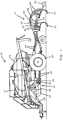
Fig. 12 is side view of the meter ofFig. 9 showing the connecting arm of the shut-off in a released position to enable removal of the meter roller. - An air seeder constructed according to a preferred embodiment of the present invention is shown in the figures. With reference to
Fig. 1 , an air seeder is shown comprising of aseed cart 10 towed between a tractor (not shown) and a tilling implement 12. Theseed cart 10 has aframe 14 to whichproduct tanks 16 andwheels 18 are mounted. Eachproduct tank 16 has an associatedmetering system 20 at its lower end for controlled feeding of product into apneumatic distribution system 22 at aprimary distribution manifold 24. The tilling implement 12, towed behind theseed cart 10, consists generally of aframe 30 to whichground openers 32 are mounted. Incorporation of seed row finishing equipment such asclosing wheels 34 is also desirable in many applications. - The
pneumatic distribution system 22 includes acentrifugal fan 36 connected to aplenum 38, which is in turn connected to one or moreprimary distribution manifolds 24, each associated with aproduct tank 16. The individual passages in theprimary distribution manifold 24 are each connected by adistribution line 40 to ariser tube 42, only one of which is shown. Eachriser tube 42 is in turn coupled to asecondary distribution header 44.Distribution lines 46 connect thesecondary distribution header 44 to seed boots mounted on theground openers 32 to deliver product, seed or fertilizer, etc. to the furrow formed by theopeners 32. Further detail of the air seeder can be found inUS Patent No. 5,878,679 . While the air seeder ofFig. 1 is shown as a separate air cart connected to a tilling implement, theproduct tanks 16,metering system 20 anddistribution system 22 can be mounted to the same frame as theground openers 32. - The
metering system 20 will now be described in greater detail with reference toFigs. 2-5 .Metering system 20 includes ahousing 50 having anupper end 52 that is coupled to aproduct tank 16. Thehousing 50 further has alower end 54 that is coupled to theprimary manifold 24 of the pneumatic distribution system. Thehousing 50 forms aninlet passage 56 through which product is received into the housing and anoutlet passage 58 through which metered product is delivered to the distribution system. A rotary cut offvalve 60 is placed in theinlet passage 56 and can be rotated as shown by thearrow 62 from the open position shown inFig. 2 to a cleanout position in which product is discharged from thehousing 50 to enable theproduct tank 16 to be emptied without the product flowing through the meter to the distribution system. - The
inlet passage 56 leads to ameter cartridge 70 which houses ameter roller 72. Thecartridge 70 is removable from themeter housing 50 as shown inFig. 4 where thecartridge 70 is shown partially withdrawn from thehousing 50. The cartridge consists of a plurality ofmeter casings 74 placed adjacent to one another and fastened together byelongated bolts 84,Fig. 5 , extending throughapertures 76 in the meter casings. Themeter roller 72 is constructed of a plurality ofroller segments 78 axially positioned along adrive shaft 80. In the embodiment shown, thedrive shaft 80 is hex shaped to mate with the hex shaped bore 92 in theroller segments 78. Additional attaching hardware is shown and described in the above referencedUS Patent No. 5,878,679 . - Each
roller segment 78 is disposed within aseparate meter casing 74. Eachmeter casing 74 has aradial wall 86 along one axial end of the casing that separates adjacent roller segments from one another axially along theshaft 80. Eachcasing 74 defines aninlet 88 in communication with theinlet passage 56 of the meter housing for receiving product therefrom. As themeter roller 72 rotates, as shown by thearrow 90 inFig. 2 , product is displaced by the teeth andgrooves 92 of the rollers, over theledge 94 to theoutlet 96 in the meter casing. From there product flows to theoutlet passage 58 in the meter housing and to themanifold 24 of thedistribution system 22. For each meter casing, a shut-offgate 100 is provided to selectively shut-off the flow of seed from a given section of the meter roller. A shut-off gate is shown inFig. 2 in the closed position preventing product from flowing over theledge 94. The shut-off gate is pivotally mounted to the meter casing atpivot 102 near a proximal end of the gate. Apivot rod 108,Fig. 5 , extends axially through the cartridge to pivotally mount the shut-offgates 100. Eachgate 100 is held in the closed position by aplunger 104 that is slidalby moved within asleeve 106 in the meter casing.Actuators 110 are mounted to themeter housing 50 with the majority of the body of theactuators 110 extending outwardly from the housing as shown inFigs. 2 and4 . The actuators have anextendable rod 112 which extends into thesleeve 106 and bears against theplunger 104 as shown inFig. 2 when the actuator is in the energized state. Preferably the actuator rod is spring biased to the retracted position so that the rod remains retracted when the actuator is in the non-energized state. The terms energized and non-energized mean when the actuating power is present or not present and can be electric, pneumatic, hydraulic, etc. When retracted, the ends ofrods 112 are contained within thehousing 50 as shown inFig. 3 , completely withdrawn from the meter casing. This allows themeter cartridge 70 to be removed from thehousing 50 as shown inFig. 4 . Theplungers 104 andsleeves 106 are contained within the respective meter casings so as to not interfere with thehousing 50 during insertion or removal of thecartridge 70 into and from thehousing 50. - A meter casing and shut-off gate are shown in greater detail in
Figs. 6 and 7 . InFig. 6 thegate 100 is shown in the closed position in which adistal end 103 of the gate bears against or is adjacent theledge 94 to prevent product from flowing over the ledge. InFig. 7 , the gate is shown in the open position, spaced from theledge 94, allowing product to flow over the ledge to theoutlet 96. Thegate 100 is integrally formed with aspring tab 114 extending upward from thepivot 102 as shown inFigs. 6 and 7 . The spring tab bears against an inner surface of thecasing member 74 in the open position shown inFig. 7 . When the gate is moved to the closed position, thespring tab 114 is deflected as shown inFig. 6 . When therod 112 of theactuator 110 is retracted, the spring tab provides a biasing force to move thegate 100 to the open position. Separate spring members can be used between the gate and the casing member to bias the gate to the open position in place of theintegral spring tab 114. These could include a tension spring between the gate and casing near todistal end 103 of the gate or a coil spring at thepivot 102. - The
actuators 110 can be electronic, pneumatic, hydraulic, or any other actuator that provides the desired motion and are preferably electronically controlled. Theactuators 110 can be controlled selectively by the operator through a control panel in the tractor cab or, preferably, the actuators are controlled by field mapping software in combination with GPS or other vehicle positioning system. With the use of field maps and vehicle positioning, the actuators will be activated to close product flow from the meter, and thus stop product flow to one or more of thedistribution lines 40 which supply product to one or more rows of the tilling implement 12, as the tilling implement covers area which has already been seeded or which should not be seeded. - An alternative implementation of the invention is shown in
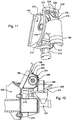
Figs. 8-12 . Here the pivoting shut-off gates are incorporated into a different meter, in this case, the meter is from a John Deere 1990CCS No-Till Air Drill. Themetering system 120 is shown inFig. 8 without the sectional shut-off of the present invention to provide the context for the invention. Themetering system 120 includes ameter box assembly 150 upon which a product tank (not shown) is supported and supplies product into theopen interior 148 of the meter box assembly. A metering system driveshaft 180 is supported by meter box assembly and carries a meter roller having a plurality ofroller segments 178. Theroller segments 178 are axially spaced from one another along the length of thedrive shaft 180. Surrounding each roller segment is afeed cup 168 which is open to theinterior 148 of the meter box assembly to receive product therefrom. Eachfeed cup 168 also forms anoutlet tube 169 to direct product to the air stream of theproduct distribution system 122 shown inFigs. 9, 10 and12 . - During operation, rotation of the roller segments, counter-clockwise as shown in
Figs. 9 and 10 , causes product flow over theledge 194 of the feed cup and into thetube 169. A shut-offgate 200 is pivotally mounted to each feed cup at thepivot 202 at the upper end of both the gate and the feed cup.Actuators 210 are mounted to anair manifold 212 formed as part of the meter box assembly with one actuator beneath each feed cup. Each actuator has an extendable rod 213 (Fig. 11 ) coupled to aclevis 214. Aconnector arm 216 is coupled to the clevis and extends upward, around the exterior of the feed cup, to the shut-offgate 200. In the preferred embodiment shown, the connector arm is U-shaped having a pair oflegs 218, one on each side of the feed cup. The legs are curved to maintain clearance with bearing assemblies (not shown) on thedrive shaft 180. At the upper ends of the connector arm, thelegs 218 are connected to each other by across bar 220. As shown, the connector arm is made of a single molded resin member forming thelegs 218 andcross bar 220. The cross bar is also U-shaped itself to arch over the shut-offgate 200. The connector arm could be fabricated of metal instead of molded resin. Apivot pin 222 also extends between the twolegs 218 of the connector arm near thecross bar 220. The connector arm is releasably coupled to the shut-offgate 200 by seating thepivot pin 222 into thehooks 224 formed in the shut-offgate 200. Aspring clip 226, riveted or otherwise fastened to the gate, bears against thepivot pin 222 to hold the pivot pin seated in thehooks 224. - The
actuators 210 are air cylinders that are reverse acting. Therod 213 is normally extended by an internal spring. When the actuators are energized by compressed air, the actuator rod retracts. In the non-energized state, the rod is extended as shown inFig. 9 . This holds thegate 200 in the open position, allowing product to flow through the feed cups when the roller segments of the meter are rotated. When the actuator is energized and the rod is retracted, the gate moves to the closed position shown inFig. 10 , preventing product flow. A suitable air cylinder is a model "Flat I" air cylinder available from Bimba Manufacturing of University Park, Illinois. This cylinder is a reverse acting, spring return, rod normally extended cylinder. Electric or hydraulic or other actuators can be used in place of the air cylinder shown. The connector arm can be released from the gate by depressing thespring clip 226 to withdraw thepivot pin 222 from thehooks 224 on the gate. This allows the connector arm to be pivoted around the feed cup to a clearance position shown inFig. 12 to allow theroller segments 178 and driveshaft 180 to be removed through the open upper end of the feed cups. This enables different size and shaped roller segments to be used in the seed meter. Differently shapedgates 200 may also be used with thedifferent roller segments 178 depending in the size of the roller segments. The gates can be changed by removing the pivot pins 202 attaching the gates to the respective feed cups. - In the embodiment of the invention shown in
Fig. 9-12 , the actuators for the shut-off gates are positioned beneath the roller segments and are connected to the respective gates by connector arms that extend around the feed cup. The connector arm can extend around both sides of the feed cup as shown or have only one leg extending around one side of the feed cup. The actuators can be mounted above the roller segments and have rods that extend downward and connect directly to the shut-off gates. This arrangement may not provide as much access to the roller segments for changing of the segments. - While the invention has been shown and described with a pivoting shut-off gate, other types of motion can be used to move the gate between open and closed positions such as a slide gate as shown in the above referenced patent publication.
- The shut-off gate for a volumetric meter of the present invention, located after the meter roller but before product has moved into the air stream, overcomes the challenges described above. The long delay between shut-off and the termination of product discharge at the row is reduced since the meter does not need to empty before product flow ceases. Since the product is stopped before the product enters the air stream, diversion of the product back to the tank is not needed. This avoids the need to separate mixed products and avoids the difficulty of returning product to a pressurized tank. While the invention has been shown and described in the context of an air seeder, it will be appreciated by those skilled in the art that the invention can be used with any volumetric meter such as a grain drill that uses gravity to distribute seed from the meter to the ground.
- Having described the preferred embodiment, it will become apparent that various modifications can be made without departing from the scope of the invention as defined in the accompanying claims.
Claims (15)
- A volumetric metering system (20) for metering a product in a seeding machine (10) having a product tank (16) and a distribution system (22) for distributing the metered product, said metering system (20) comprising: a meter roller (72) having a plurality of roller segments (78, 178) aligned along a roller axis for metering product from the tank (16) to the distribution system (22), characterized in that a plurality of gates (100, 200) are disposed axially along the meter roller (72) between the meter roller (72) and the distribution system (22) and are movable between an open position, in which product is allowed to flow from the meter roller (72) to the distribution system (22), and a closed position, in which product is prevented from flowing from the meter roller (72) to the distribution system (22); and more of actuators (110, 210), each actuator (110, 210) arranged to selectively move one gate (100, 200) from the open to the closed positions, further comprising meter casings (74) within which each roller segment (72) is disposed, each meter casing (74) defining an inlet (88) from the tank (16) into the meter casing (74) and an outlet (96) from the meter casing (74) to the distribution system (22), wherein each gate (100, 200) is pivotally mounted to a meter casing (74) and each meter casing (74) is provided with the shut-off gate (100, 200) to selectively shut-off the flow of seed from a given section of the meter roller (72).
- The metering system (20) of claim 1 wherein the gates (100, 200) are pivotally mounted for rotation between the open and closed positions.
- The metering system (20) of claim 1 wherein the actuators (110, 210) have a non-energized state and an energized state, when in the energized state, the actuators (110, 210) move the gates (100, 200) to the closed positions.
- The metering system (20) of claim 3 further comprising bias means (114) to hold the gates (100, 200) in their open positions when the actuators (110, 210) are in their non-energized state.
- The metering system (20) of claim 1 wherein the actuators (110, 210) are coupled and selectively releasable from the gates (100, 200).
- The metering system (20) of claim 1 wherein the actuators (110, 210) are coupled to the gates (100, 200) and wherein the actuator (110, 210) is spring biased to move the gates (100, 200) to the open position when the actuators (110, 210) are in the non-energized state.
- The metering system (20) of claim 1 wherein each gate (100, 200) includes a spring portion that engages the meter casing (74) and which is deflected when the gate (100) is moved to the closed position to bias the gate (100) toward the open position.
- The metering system (20) of claim 1 wherein the meter casing (74) defines a ledge (94) over which product flows to the outlet (96) and wherein the gate (100) is pivotally coupled to the meter casing (74) at a proximal end of the gate (100) and the distal end of the gate (100) is adjacent the ledge (94) when in the closed position.
- The metering system (20) of claim 1 further comprising a meter housing (50) and wherein the meter casings (74) and the meter roller (72) form a meter cartridge (70) removably mounted in the housing (50), said actuators (110, 210) being mounted to the housing (50).
- The metering system (20) of claim 9 wherein the actuators (110,210) each have an extendable rod (112, 213) that is extendable into the meter casing (74) to move the gates (100, 200) to the closed position and which is retractable from the meter casings (74) to enable removal of the meter cartridge (70).
- The metering system (20) of claim 10 further comprising a plunger (104) slidably mounted within the meter casing (74) between the actuators (110) and the gates (100) wherein the actuator (110) moves the plungers (104) into engagement with the gates (100) to move the gates (100) to the closed positions.
- The metering system (20) of cl6aim 1 wherein the roller segments (178) are spaced along a roller drive shaft (180) and further comprising a separate feed cup (168) surrounding each roller segment (178) having an inlet (148) to receive product from the product tank (16) and an outlet (169) through which product is directed to the distribution system (122) and wherein each shut-off gate (200) is mounted to an associated feed cup (168) for movement between the open and closed positions.
- The metering system (20) of claim 12 wherein the feed cups (168) are open from above exposing in the roller segments (178) and wherein the gates (200) cover the roller segments (178), said actuators (210) being located below the feed cups (168) and further comprising connecting arms (216) extending between an actuator rods (213) and the gates (200), wherein the connecting arms (216) wrap around the feed cups (168) and are releaseably coupled to the gates (200).
- The metering system (20) of claim 13 wherein the connecting arms (216) are generally U-shaped having a pair of legs (218) extending around opposite sides of the feed cups (168) and a cross bar (220) connecting the pair of legs (218) above the gates (200), the connecting arms (216) further comprising a pivot pin (222) also extending between the legs (218) above the gates (200), the pivot pins (222) being seated into hooks (224) on the gates (200), and further comprising a releasable spring clip (226) on each gate (200) to hold the pivot pins (222) in the hooks (224).
- The metering system (20) of claim 12 wherein each feed cup (168) forms a ledge (194) over which product flows from the meter roller (178) and wherein the shut-off gates (200), when in the closed positions, stop flow of product over the ledges (194).
Priority Applications (1)
| Application Number | Priority Date | Filing Date | Title |
|---|---|---|---|
| PL10164716T PL2260689T3 (en) | 2009-06-09 | 2010-06-02 | Metering system |
Applications Claiming Priority (1)
| Application Number | Priority Date | Filing Date | Title |
|---|---|---|---|
| US12/481,254 US8132521B2 (en) | 2009-06-09 | 2009-06-09 | Volumetric metering system with sectional shut-off |
Publications (3)
| Publication Number | Publication Date |
|---|---|
| EP2260689A1 EP2260689A1 (en) | 2010-12-15 |
| EP2260689B1 EP2260689B1 (en) | 2013-03-27 |
| EP2260689B2 true EP2260689B2 (en) | 2020-02-12 |
Family
ID=42827321
Family Applications (1)
| Application Number | Title | Priority Date | Filing Date |
|---|---|---|---|
| EP10164716.2A Active EP2260689B2 (en) | 2009-06-09 | 2010-06-02 | Metering system |
Country Status (11)
| Country | Link |
|---|---|
| US (1) | US8132521B2 (en) |
| EP (1) | EP2260689B2 (en) |
| AR (1) | AR077029A1 (en) |
| AU (1) | AU2010202169B2 (en) |
| BR (1) | BRPI1002303B1 (en) |
| CA (1) | CA2704887C (en) |
| ES (1) | ES2415933T3 (en) |
| MX (1) | MX2010006140A (en) |
| PL (1) | PL2260689T3 (en) |
| RU (1) | RU2530994C2 (en) |
| UA (1) | UA106198C2 (en) |
Families Citing this family (39)
| Publication number | Priority date | Publication date | Assignee | Title |
|---|---|---|---|---|
| US8678347B2 (en) * | 2010-09-20 | 2014-03-25 | Deere & Company | Manifold actuator assembly |
| US8671857B2 (en) | 2011-03-10 | 2014-03-18 | Cnh Canada, Ltd. | Variable geometry meter roller |
| US20140076218A1 (en) | 2012-09-14 | 2014-03-20 | James Z. Liu | Product distribution device with flow rate and section control monitoring |
| US9265188B2 (en) | 2012-12-07 | 2016-02-23 | Cnh Industrial Canada, Ltd. | Sectioned meter box assembly |
| US9591799B2 (en) * | 2013-01-25 | 2017-03-14 | Cnh Industrial Canada, Ltd. | Metering of product in an air cart on hilly terrain |
| US9420738B2 (en) * | 2013-06-12 | 2016-08-23 | Agco Corporation | Low rate metering wheel for coarse granules |
| DK2862430T3 (en) | 2013-10-16 | 2016-04-11 | Kverneland As | Dosing device for dosing bulk material |
| CA2886436C (en) | 2014-03-31 | 2022-05-24 | Salford Group Inc. | Metering apparatuses for sectional control |
| CA2905014C (en) | 2014-11-04 | 2020-03-10 | Cnh Industrial Canada, Ltd. | Flow control assembly for an agricultural metering system |
| CN105659999A (en) * | 2014-11-19 | 2016-06-15 | 现代农装科技股份有限公司 | Air-suction vegetable seedling-raising and precision seeding roller |
| DE102015101572A1 (en) | 2015-02-04 | 2016-08-04 | Horsch Maschinen Gmbh | Pneumatic seed drill |
| US20160330901A1 (en) * | 2015-05-14 | 2016-11-17 | Deere & Company | Product distribution device with section control monitoring |
| US9861030B2 (en) * | 2015-09-23 | 2018-01-09 | Deere & Company | Biased guide to reduce variation in a volumetric meter |
| US9949427B2 (en) | 2015-09-30 | 2018-04-24 | Deere & Company | System and method of distributing seeds and agricultural particles |
| US9814173B2 (en) | 2015-09-30 | 2017-11-14 | Deere & Company | Seeding system |
| US20170086351A1 (en) | 2015-09-30 | 2017-03-30 | Deere & Company | Seed metering system and method of operating the same |
| US10492359B2 (en) | 2015-09-30 | 2019-12-03 | Deere & Company | Seeding system |
| US10085375B2 (en) | 2016-06-28 | 2018-10-02 | Cnh Industrial Canada, Ltd. | Sectional control system for delivery of agricultural product according to location |
| DE102016112058A1 (en) * | 2016-07-01 | 2018-01-04 | Amazonen-Werke H. Dreyer Gmbh & Co. Kg | Agricultural distributor with cover |
| CA2977467A1 (en) | 2016-10-11 | 2018-04-11 | Deere & Company | Seeding system |
| US10563774B2 (en) | 2017-06-30 | 2020-02-18 | Intelligent Agricultural Solutions Llc | Sectional control device |
| US10609858B2 (en) | 2017-09-21 | 2020-04-07 | Deere & Company | Commodity metering system for work vehicle and calibration method for same |
| US10575457B2 (en) | 2017-09-21 | 2020-03-03 | Deere & Company | Commodity metering system with speed compensation based on machine tilt and methods for operating the same |
| US11191207B2 (en) | 2017-09-21 | 2021-12-07 | Deere & Company | Commodity metering system for work vehicle and calibration method for same |
| US10942053B2 (en) | 2018-05-14 | 2021-03-09 | Deere & Company | Seeding system |
| US11140811B2 (en) | 2018-06-13 | 2021-10-12 | Deere & Company | Commodity metering system for work vehicle with rollers in staggered arrangement |
| CN109005801A (en) * | 2018-06-28 | 2018-12-18 | 安徽灵杨农机制造有限公司 | A kind of pea seeder |
| IT201800007355A1 (en) * | 2018-07-19 | 2020-01-19 | Adjustable distributor group for granulated materials and the like | |
| DE102018006660A1 (en) * | 2018-08-23 | 2020-02-27 | Rauch Landmaschinenfabrik Gmbh | Dosing unit for powder or particulate material to be distributed and distribution machine with such a dosing unit |
| US10986773B2 (en) | 2019-02-19 | 2021-04-27 | Cnh Industrial Canada, Ltd. | Look-ahead functionality tuning for independent sections |
| US11765991B2 (en) | 2019-11-14 | 2023-09-26 | Cnh Industrial Canada, Ltd. | Particulate material metering system for an agricultural implement |
| CA3097708A1 (en) | 2019-11-14 | 2021-05-14 | Cnh Industrial Canada, Ltd. | Particulate material metering system for an agricultural implement |
| US11770996B2 (en) * | 2020-02-03 | 2023-10-03 | Cnh Industrial America Llc | Housing for a modular meter assembly of a dry product applicator |
| US11555726B2 (en) | 2020-03-05 | 2023-01-17 | Cnh Industrial Canada, Ltd. | Metering system for distributing particulate material |
| US20220132726A1 (en) * | 2020-10-30 | 2022-05-05 | Deere & Company | Removable roller with rotation indicator |
| RU2759322C1 (en) * | 2021-01-11 | 2021-11-11 | Федеральное государственное бюджетное образовательное учреждение высшего образования "Кубанский государственный аграрный университет имени И.Т. Трубилина" | Sowing device with simultaneous application of the main fertilizer |
| CN114271073B (en) * | 2022-01-04 | 2023-05-23 | 许昌市农业技术推广站 | Wheat seed manure suppression all-in-one seeder |
| DE102022112265A1 (en) | 2022-05-17 | 2023-11-23 | Amazonen-Werke H. Dreyer SE & Co. KG | Machine for spreading seeds |
| CN118275433B (en) * | 2024-05-31 | 2024-07-30 | 西北农林科技大学 | Quarantine weed seed detection device and method |
Citations (2)
| Publication number | Priority date | Publication date | Assignee | Title |
|---|---|---|---|---|
| AT383720B (en) † | 1985-02-05 | 1987-08-10 | Groemer Hubert | Seed drill designed as a tractor-mounted appliance |
| US20090079624A1 (en) † | 2007-09-21 | 2009-03-26 | Dean Brian F | Sectional meter shut-off and agricultural implement having sectional meter shut-off |
Family Cites Families (10)
| Publication number | Priority date | Publication date | Assignee | Title |
|---|---|---|---|---|
| US4023707A (en) * | 1973-03-08 | 1977-05-17 | Johnson Leroy E | Seeder with seed flow modification for marking seeded fields |
| DK353279A (en) * | 1979-08-24 | 1981-02-25 | Nordsten As P | MACHINE FOR SPREADING CORN MATERIAL |
| SU927682A1 (en) * | 1980-03-12 | 1982-05-15 | Башкирский сельскохозяйственный институт | Metering-out feeder of pneumatic transport installation |
| RU2089057C1 (en) * | 1995-02-27 | 1997-09-10 | Всероссийский научно-исследовательский институт орошаемого земледелия | Drill |
| US5878679A (en) * | 1997-08-18 | 1999-03-09 | Deere & Company | Product disconnect for metering device |
| US5826523A (en) * | 1997-08-18 | 1998-10-27 | Deere & Company | Brush for air seeder metering system |
| CA2311698C (en) * | 2000-06-15 | 2003-05-06 | Bourgault Industries Ltd. | Seeder calibration apparatus and method |
| CA2566248C (en) * | 2006-03-06 | 2013-10-08 | Patrick Audette | Multi configuration distribution system for a drill or the like |
| RU2356208C2 (en) * | 2007-05-10 | 2009-05-27 | Анистрад Григорьевич Васильев | Method of green manure crop seeding and device for its implementation |
| PL2022309T3 (en) | 2007-08-08 | 2012-11-30 | Amazonen Werke Dreyer H | Pneumatic sowing machine |
-
2009
- 2009-06-09 US US12/481,254 patent/US8132521B2/en active Active
-
2010
- 2010-05-21 CA CA2704887A patent/CA2704887C/en active Active
- 2010-05-27 AU AU2010202169A patent/AU2010202169B2/en active Active
- 2010-06-02 EP EP10164716.2A patent/EP2260689B2/en active Active
- 2010-06-02 ES ES10164716T patent/ES2415933T3/en active Active
- 2010-06-02 PL PL10164716T patent/PL2260689T3/en unknown
- 2010-06-04 MX MX2010006140A patent/MX2010006140A/en active IP Right Grant
- 2010-06-08 BR BRPI1002303-8A patent/BRPI1002303B1/en active IP Right Grant
- 2010-06-08 RU RU2010123395/13A patent/RU2530994C2/en not_active IP Right Cessation
- 2010-06-09 UA UAA201007122A patent/UA106198C2/en unknown
- 2010-06-09 AR ARP100102019A patent/AR077029A1/en unknown
Patent Citations (2)
| Publication number | Priority date | Publication date | Assignee | Title |
|---|---|---|---|---|
| AT383720B (en) † | 1985-02-05 | 1987-08-10 | Groemer Hubert | Seed drill designed as a tractor-mounted appliance |
| US20090079624A1 (en) † | 2007-09-21 | 2009-03-26 | Dean Brian F | Sectional meter shut-off and agricultural implement having sectional meter shut-off |
Also Published As
| Publication number | Publication date |
|---|---|
| AU2010202169A1 (en) | 2010-12-23 |
| AU2010202169B2 (en) | 2016-05-19 |
| MX2010006140A (en) | 2010-12-13 |
| AR077029A1 (en) | 2011-07-27 |
| BRPI1002303A2 (en) | 2012-02-07 |
| US8132521B2 (en) | 2012-03-13 |
| RU2530994C2 (en) | 2014-10-20 |
| US20100307394A1 (en) | 2010-12-09 |
| BRPI1002303B1 (en) | 2023-01-24 |
| UA106198C2 (en) | 2014-08-11 |
| CA2704887A1 (en) | 2010-12-09 |
| EP2260689B1 (en) | 2013-03-27 |
| ES2415933T3 (en) | 2013-07-29 |
| EP2260689A1 (en) | 2010-12-15 |
| RU2010123395A (en) | 2011-12-20 |
| PL2260689T3 (en) | 2013-08-30 |
| CA2704887C (en) | 2017-09-26 |
Similar Documents
| Publication | Publication Date | Title |
|---|---|---|
| EP2260689B2 (en) | Metering system | |
| CA2716678C (en) | Volumetric metering system with sectional shut-off | |
| AU2010246522B2 (en) | Volumetric metering system with clutch based sectional shut-off | |
| EP2430897B1 (en) | Manifold actuator system and seed metering system with such or locking apparatus with such |
Legal Events
| Date | Code | Title | Description |
|---|---|---|---|
| PUAI | Public reference made under article 153(3) epc to a published international application that has entered the european phase |
Free format text: ORIGINAL CODE: 0009012 |
|
| AK | Designated contracting states |
Kind code of ref document: A1 Designated state(s): AL AT BE BG CH CY CZ DE DK EE ES FI FR GB GR HR HU IE IS IT LI LT LU LV MC MK MT NL NO PL PT RO SE SI SK SM TR |
|
| AX | Request for extension of the european patent |
Extension state: BA ME RS |
|
| 17P | Request for examination filed |
Effective date: 20110615 |
|
| GRAP | Despatch of communication of intention to grant a patent |
Free format text: ORIGINAL CODE: EPIDOSNIGR1 |
|
| RIC1 | Information provided on ipc code assigned before grant |
Ipc: A01C 7/08 20060101AFI20121112BHEP |
|
| GRAS | Grant fee paid |
Free format text: ORIGINAL CODE: EPIDOSNIGR3 |
|
| GRAA | (expected) grant |
Free format text: ORIGINAL CODE: 0009210 |
|
| AK | Designated contracting states |
Kind code of ref document: B1 Designated state(s): AL AT BE BG CH CY CZ DE DK EE ES FI FR GB GR HR HU IE IS IT LI LT LU LV MC MK MT NL NO PL PT RO SE SI SK SM TR |
|
| REG | Reference to a national code |
Ref country code: GB Ref legal event code: FG4D |
|
| REG | Reference to a national code |
Ref country code: CH Ref legal event code: EP |
|
| REG | Reference to a national code |
Ref country code: AT Ref legal event code: REF Ref document number: 602746 Country of ref document: AT Kind code of ref document: T Effective date: 20130415 |
|
| REG | Reference to a national code |
Ref country code: IE Ref legal event code: FG4D |
|
| REG | Reference to a national code |
Ref country code: DE Ref legal event code: R096 Ref document number: 602010005729 Country of ref document: DE Effective date: 20130529 |
|
| REG | Reference to a national code |
Ref country code: ES Ref legal event code: FG2A Ref document number: 2415933 Country of ref document: ES Kind code of ref document: T3 Effective date: 20130729 |
|
| PG25 | Lapsed in a contracting state [announced via postgrant information from national office to epo] |
Ref country code: BG Free format text: LAPSE BECAUSE OF FAILURE TO SUBMIT A TRANSLATION OF THE DESCRIPTION OR TO PAY THE FEE WITHIN THE PRESCRIBED TIME-LIMIT Effective date: 20130627 Ref country code: NO Free format text: LAPSE BECAUSE OF FAILURE TO SUBMIT A TRANSLATION OF THE DESCRIPTION OR TO PAY THE FEE WITHIN THE PRESCRIBED TIME-LIMIT Effective date: 20130627 Ref country code: LT Free format text: LAPSE BECAUSE OF FAILURE TO SUBMIT A TRANSLATION OF THE DESCRIPTION OR TO PAY THE FEE WITHIN THE PRESCRIBED TIME-LIMIT Effective date: 20130327 Ref country code: SE Free format text: LAPSE BECAUSE OF FAILURE TO SUBMIT A TRANSLATION OF THE DESCRIPTION OR TO PAY THE FEE WITHIN THE PRESCRIBED TIME-LIMIT Effective date: 20130327 |
|
| REG | Reference to a national code |
Ref country code: AT Ref legal event code: MK05 Ref document number: 602746 Country of ref document: AT Kind code of ref document: T Effective date: 20130327 |
|
| REG | Reference to a national code |
Ref country code: LT Ref legal event code: MG4D |
|
| PG25 | Lapsed in a contracting state [announced via postgrant information from national office to epo] |
Ref country code: GR Free format text: LAPSE BECAUSE OF FAILURE TO SUBMIT A TRANSLATION OF THE DESCRIPTION OR TO PAY THE FEE WITHIN THE PRESCRIBED TIME-LIMIT Effective date: 20130628 Ref country code: LV Free format text: LAPSE BECAUSE OF FAILURE TO SUBMIT A TRANSLATION OF THE DESCRIPTION OR TO PAY THE FEE WITHIN THE PRESCRIBED TIME-LIMIT Effective date: 20130327 Ref country code: SI Free format text: LAPSE BECAUSE OF FAILURE TO SUBMIT A TRANSLATION OF THE DESCRIPTION OR TO PAY THE FEE WITHIN THE PRESCRIBED TIME-LIMIT Effective date: 20130327 Ref country code: FI Free format text: LAPSE BECAUSE OF FAILURE TO SUBMIT A TRANSLATION OF THE DESCRIPTION OR TO PAY THE FEE WITHIN THE PRESCRIBED TIME-LIMIT Effective date: 20130327 |
|
| REG | Reference to a national code |
Ref country code: PL Ref legal event code: T3 |
|
| REG | Reference to a national code |
Ref country code: NL Ref legal event code: VDEP Effective date: 20130327 |
|
| PG25 | Lapsed in a contracting state [announced via postgrant information from national office to epo] |
Ref country code: HR Free format text: LAPSE BECAUSE OF FAILURE TO SUBMIT A TRANSLATION OF THE DESCRIPTION OR TO PAY THE FEE WITHIN THE PRESCRIBED TIME-LIMIT Effective date: 20130327 Ref country code: BE Free format text: LAPSE BECAUSE OF FAILURE TO SUBMIT A TRANSLATION OF THE DESCRIPTION OR TO PAY THE FEE WITHIN THE PRESCRIBED TIME-LIMIT Effective date: 20130327 |
|
| PG25 | Lapsed in a contracting state [announced via postgrant information from national office to epo] |
Ref country code: CZ Free format text: LAPSE BECAUSE OF FAILURE TO SUBMIT A TRANSLATION OF THE DESCRIPTION OR TO PAY THE FEE WITHIN THE PRESCRIBED TIME-LIMIT Effective date: 20130327 Ref country code: AT Free format text: LAPSE BECAUSE OF FAILURE TO SUBMIT A TRANSLATION OF THE DESCRIPTION OR TO PAY THE FEE WITHIN THE PRESCRIBED TIME-LIMIT Effective date: 20130327 Ref country code: RO Free format text: LAPSE BECAUSE OF FAILURE TO SUBMIT A TRANSLATION OF THE DESCRIPTION OR TO PAY THE FEE WITHIN THE PRESCRIBED TIME-LIMIT Effective date: 20130327 Ref country code: PT Free format text: LAPSE BECAUSE OF FAILURE TO SUBMIT A TRANSLATION OF THE DESCRIPTION OR TO PAY THE FEE WITHIN THE PRESCRIBED TIME-LIMIT Effective date: 20130729 Ref country code: SK Free format text: LAPSE BECAUSE OF FAILURE TO SUBMIT A TRANSLATION OF THE DESCRIPTION OR TO PAY THE FEE WITHIN THE PRESCRIBED TIME-LIMIT Effective date: 20130327 Ref country code: EE Free format text: LAPSE BECAUSE OF FAILURE TO SUBMIT A TRANSLATION OF THE DESCRIPTION OR TO PAY THE FEE WITHIN THE PRESCRIBED TIME-LIMIT Effective date: 20130327 Ref country code: IS Free format text: LAPSE BECAUSE OF FAILURE TO SUBMIT A TRANSLATION OF THE DESCRIPTION OR TO PAY THE FEE WITHIN THE PRESCRIBED TIME-LIMIT Effective date: 20130727 Ref country code: NL Free format text: LAPSE BECAUSE OF FAILURE TO SUBMIT A TRANSLATION OF THE DESCRIPTION OR TO PAY THE FEE WITHIN THE PRESCRIBED TIME-LIMIT Effective date: 20130327 |
|
| REG | Reference to a national code |
Ref country code: HU Ref legal event code: AG4A Ref document number: E017191 Country of ref document: HU |
|
| PG25 | Lapsed in a contracting state [announced via postgrant information from national office to epo] |
Ref country code: CY Free format text: LAPSE BECAUSE OF FAILURE TO SUBMIT A TRANSLATION OF THE DESCRIPTION OR TO PAY THE FEE WITHIN THE PRESCRIBED TIME-LIMIT Effective date: 20130327 |
|
| PLBI | Opposition filed |
Free format text: ORIGINAL CODE: 0009260 |
|
| 26 | Opposition filed |
Opponent name: AMAZONEN-WERKE H. DREYER GMBH & CO. KG Effective date: 20131220 |
|
| PG25 | Lapsed in a contracting state [announced via postgrant information from national office to epo] |
Ref country code: MC Free format text: LAPSE BECAUSE OF FAILURE TO SUBMIT A TRANSLATION OF THE DESCRIPTION OR TO PAY THE FEE WITHIN THE PRESCRIBED TIME-LIMIT Effective date: 20130327 Ref country code: DK Free format text: LAPSE BECAUSE OF FAILURE TO SUBMIT A TRANSLATION OF THE DESCRIPTION OR TO PAY THE FEE WITHIN THE PRESCRIBED TIME-LIMIT Effective date: 20130327 |
|
| PLAX | Notice of opposition and request to file observation + time limit sent |
Free format text: ORIGINAL CODE: EPIDOSNOBS2 |
|
| REG | Reference to a national code |
Ref country code: DE Ref legal event code: R026 Ref document number: 602010005729 Country of ref document: DE Effective date: 20131220 |
|
| REG | Reference to a national code |
Ref country code: IE Ref legal event code: MM4A |
|
| PG25 | Lapsed in a contracting state [announced via postgrant information from national office to epo] |
Ref country code: IE Free format text: LAPSE BECAUSE OF NON-PAYMENT OF DUE FEES Effective date: 20130602 |
|
| PLBB | Reply of patent proprietor to notice(s) of opposition received |
Free format text: ORIGINAL CODE: EPIDOSNOBS3 |
|
| PGFP | Annual fee paid to national office [announced via postgrant information from national office to epo] |
Ref country code: GB Payment date: 20140627 Year of fee payment: 5 |
|
| PGFP | Annual fee paid to national office [announced via postgrant information from national office to epo] |
Ref country code: IT Payment date: 20140621 Year of fee payment: 5 Ref country code: ES Payment date: 20140626 Year of fee payment: 5 |
|
| PGFP | Annual fee paid to national office [announced via postgrant information from national office to epo] |
Ref country code: PL Payment date: 20140521 Year of fee payment: 5 Ref country code: HU Payment date: 20140527 Year of fee payment: 5 |
|
| REG | Reference to a national code |
Ref country code: CH Ref legal event code: PL |
|
| PG25 | Lapsed in a contracting state [announced via postgrant information from national office to epo] |
Ref country code: MT Free format text: LAPSE BECAUSE OF FAILURE TO SUBMIT A TRANSLATION OF THE DESCRIPTION OR TO PAY THE FEE WITHIN THE PRESCRIBED TIME-LIMIT Effective date: 20130327 |
|
| PG25 | Lapsed in a contracting state [announced via postgrant information from national office to epo] |
Ref country code: CH Free format text: LAPSE BECAUSE OF NON-PAYMENT OF DUE FEES Effective date: 20140630 Ref country code: LI Free format text: LAPSE BECAUSE OF NON-PAYMENT OF DUE FEES Effective date: 20140630 |
|
| PG25 | Lapsed in a contracting state [announced via postgrant information from national office to epo] |
Ref country code: SM Free format text: LAPSE BECAUSE OF FAILURE TO SUBMIT A TRANSLATION OF THE DESCRIPTION OR TO PAY THE FEE WITHIN THE PRESCRIBED TIME-LIMIT Effective date: 20130327 |
|
| PG25 | Lapsed in a contracting state [announced via postgrant information from national office to epo] |
Ref country code: TR Free format text: LAPSE BECAUSE OF FAILURE TO SUBMIT A TRANSLATION OF THE DESCRIPTION OR TO PAY THE FEE WITHIN THE PRESCRIBED TIME-LIMIT Effective date: 20130327 |
|
| PG25 | Lapsed in a contracting state [announced via postgrant information from national office to epo] |
Ref country code: LU Free format text: LAPSE BECAUSE OF NON-PAYMENT OF DUE FEES Effective date: 20130602 Ref country code: MK Free format text: LAPSE BECAUSE OF FAILURE TO SUBMIT A TRANSLATION OF THE DESCRIPTION OR TO PAY THE FEE WITHIN THE PRESCRIBED TIME-LIMIT Effective date: 20130327 |
|
| PG25 | Lapsed in a contracting state [announced via postgrant information from national office to epo] |
Ref country code: IT Free format text: LAPSE BECAUSE OF NON-PAYMENT OF DUE FEES Effective date: 20150602 |
|
| GBPC | Gb: european patent ceased through non-payment of renewal fee |
Effective date: 20150602 |
|
| APAH | Appeal reference modified |
Free format text: ORIGINAL CODE: EPIDOSCREFNO |
|
| APBM | Appeal reference recorded |
Free format text: ORIGINAL CODE: EPIDOSNREFNO |
|
| APBP | Date of receipt of notice of appeal recorded |
Free format text: ORIGINAL CODE: EPIDOSNNOA2O |
|
| PG25 | Lapsed in a contracting state [announced via postgrant information from national office to epo] |
Ref country code: GB Free format text: LAPSE BECAUSE OF NON-PAYMENT OF DUE FEES Effective date: 20150602 |
|
| PG25 | Lapsed in a contracting state [announced via postgrant information from national office to epo] |
Ref country code: HU Free format text: LAPSE BECAUSE OF NON-PAYMENT OF DUE FEES Effective date: 20150603 |
|
| REG | Reference to a national code |
Ref country code: FR Ref legal event code: PLFP Year of fee payment: 7 |
|
| REG | Reference to a national code |
Ref country code: ES Ref legal event code: FD2A Effective date: 20160727 |
|
| PG25 | Lapsed in a contracting state [announced via postgrant information from national office to epo] |
Ref country code: PL Free format text: LAPSE BECAUSE OF NON-PAYMENT OF DUE FEES Effective date: 20150602 |
|
| PG25 | Lapsed in a contracting state [announced via postgrant information from national office to epo] |
Ref country code: ES Free format text: LAPSE BECAUSE OF NON-PAYMENT OF DUE FEES Effective date: 20150603 |
|
| REG | Reference to a national code |
Ref country code: FR Ref legal event code: PLFP Year of fee payment: 8 |
|
| REG | Reference to a national code |
Ref country code: FR Ref legal event code: PLFP Year of fee payment: 9 |
|
| PG25 | Lapsed in a contracting state [announced via postgrant information from national office to epo] |
Ref country code: AL Free format text: LAPSE BECAUSE OF FAILURE TO SUBMIT A TRANSLATION OF THE DESCRIPTION OR TO PAY THE FEE WITHIN THE PRESCRIBED TIME-LIMIT Effective date: 20130327 |
|
| APBU | Appeal procedure closed |
Free format text: ORIGINAL CODE: EPIDOSNNOA9O |
|
| PUAH | Patent maintained in amended form |
Free format text: ORIGINAL CODE: 0009272 |
|
| STAA | Information on the status of an ep patent application or granted ep patent |
Free format text: STATUS: PATENT MAINTAINED AS AMENDED |
|
| 27A | Patent maintained in amended form |
Effective date: 20200212 |
|
| AK | Designated contracting states |
Kind code of ref document: B2 Designated state(s): AL AT BE BG CH CY CZ DE DK EE ES FI FR GB GR HR HU IE IS IT LI LT LU LV MC MK MT NL NO PL PT RO SE SI SK SM TR |
|
| REG | Reference to a national code |
Ref country code: DE Ref legal event code: R102 Ref document number: 602010005729 Country of ref document: DE |
|
| PGFP | Annual fee paid to national office [announced via postgrant information from national office to epo] |
Ref country code: DE Payment date: 20240521 Year of fee payment: 15 |
|
| PGFP | Annual fee paid to national office [announced via postgrant information from national office to epo] |
Ref country code: FR Payment date: 20240625 Year of fee payment: 15 |