EP2260655B1 - Doppelte funkrelaisstation - Google Patents
Doppelte funkrelaisstation Download PDFInfo
- Publication number
- EP2260655B1 EP2260655B1 EP09726487.3A EP09726487A EP2260655B1 EP 2260655 B1 EP2260655 B1 EP 2260655B1 EP 09726487 A EP09726487 A EP 09726487A EP 2260655 B1 EP2260655 B1 EP 2260655B1
- Authority
- EP
- European Patent Office
- Prior art keywords
- station
- relay station
- stations
- period
- relay
- Prior art date
- Legal status (The legal status is an assumption and is not a legal conclusion. Google has not performed a legal analysis and makes no representation as to the accuracy of the status listed.)
- Active
Links
Images


Classifications
-
- H—ELECTRICITY
- H04—ELECTRIC COMMUNICATION TECHNIQUE
- H04B—TRANSMISSION
- H04B7/00—Radio transmission systems, i.e. using radiation field
- H04B7/24—Radio transmission systems, i.e. using radiation field for communication between two or more posts
- H04B7/26—Radio transmission systems, i.e. using radiation field for communication between two or more posts at least one of which is mobile
- H04B7/2603—Arrangements for wireless physical layer control
- H04B7/2606—Arrangements for base station coverage control, e.g. by using relays in tunnels
-
- H—ELECTRICITY
- H04—ELECTRIC COMMUNICATION TECHNIQUE
- H04B—TRANSMISSION
- H04B7/00—Radio transmission systems, i.e. using radiation field
- H04B7/14—Relay systems
- H04B7/15—Active relay systems
- H04B7/155—Ground-based stations
- H04B7/15528—Control of operation parameters of a relay station to exploit the physical medium
- H04B7/1555—Selecting relay station antenna mode, e.g. selecting omnidirectional -, directional beams, selecting polarizations
Definitions
- the invention relates to a relay station equipped with one or more transceiver antennas and using two radio modules, based on the same technology, which are coupled together and synchronized at the level of the medium access layer, better known as the English name MAC (Medium Access Control).
- MAC Medium Access Control
- relay stations in high-capacity communication systems for example the WiMax system
- WiMax wireless wide area network
- suburban surveillance systems or monitoring of hot spots can be mentioned.
- defense applications such as camp protection and zone control.
- the letters RF designate the radio frequency and the letters BB, the signal Base Band.
- the object of the present invention relates to system and hardware architectures (better known as hardware hardware) for the rapid and low-cost development of relay stations.
- This new approach is based in particular on the coupling of two radio modules within a relay station which are synchronized at the level of the MAC layer.
- the document entitled "Multihop communication in relay enhanced EEE 802.16 networks” presents two ways to integrate a multi-hop communication into an IEEE 802.16 system.
- the first concept follows a centralized approach where the base station has full control over the relay cell.
- the second concept follows a semi-distributed approach where a relay station controls whoever wants to join the network.
- the proposed solution takes into account the possibility of deploying directive antennas that can operate in two hierarchical levels (upper and lower), for a communication network deployed in a tree form.
- This approach is based on the implementation of fast switching low cost smart antennas or Fast Electronically Steerable Antenna (FESA).
- FESA Fast Electronically Steerable Antenna
- the tree topology consists of a higher hierarchical base station, RS relay stations and SS subscriber stations.
- n is used to designate a given hierarchy level in the network tree structure, "n-1” to designate the level of hierarchy higher than level n and "n + 1" to designate a level of hierarchy lower than level n.
- frame refers to a recurring period of time including the different resource allocations for each station. It can also be called “superframe” and is usually delimited by the transmission of synchronization patterns.
- the invention relates to a relay station RS used in a communication network having a tree architecture consisting of several hierarchical levels TL i , said communication network comprising a central point, for example a BS 0 base station. of the highest hierarchical level, one or more relay stations RS i and one or more subscriber station (s) SSi, characterized in that a relay station RS n has at least two radio modules, a first radio module being adapted to communicate with subordinate level stations TL (n + 1) and a second radio module being adapted to communicate with higher level hierarchical stations TL (n-1) , said RS uses two different frequencies for communications carried out in the lower hierarchical level TL (n + 1) and in the higher hierarchical level TL ( n-1) , the two radio modules being synchronized at their MAC layer and said relay station comprising at least one antenna connected to said MAC layer of the radio modules.
- the relaying of information is performed at the MAC layer so as to minimize end-to-end transmission delays
- the invention also relates to sharing the bandwidth between the different nodes of a network as described above.
- two modes of operation are described providing different frame structures.
- the multi-channel mode corresponds to the use of several frequency channels on the different hierarchical levels attached to the relay station.
- a relay station operates on the same frequency in the different hierarchical levels associated with it.
- the invention also relates to a transmission method or protocol implemented within a relay station having at least one of the aforementioned characteristics, characterized in that it uses an intelligent antenna and said intelligent antenna using an omnidirectional mode in the periods of the frame in which the relay station transmits in broadcast mode to the lower hierarchical level or in which the relay station receives messages transmitted in a contention period, said messages transmitted in these two periods of the frame using a robust modulation (such as than QPSK) while other transmission slots use modulations adapted to offer a higher bit rate.
- a robust modulation such as than QPSK
- the example of the description implements a FESA-type intelligent antenna in a context 802.16d and 802.16e, for example.
- the latter can also be applied to omnidirectional antennas.
- FESA intelligent antennas makes it possible to obtain a better gain and a better speed in changes of pointing direction.
- the description will also cover, by way of example, the WiMAX context, within a system comprising one or more base stations (BS), relay stations (RS) and subscriber stations (SS).
- BS base stations
- RS relay stations
- SS subscriber stations
- the figure 1 represents an exemplary architecture of a point-to-multipoint system comprising a base station BS communicating with several subscriber stations SS which are distributed in the form of a star. Such a structure offers limited coverage and limited connections too.
- the figure 2 represents an architecture that implements several RS relay stations.
- This architecture corresponds to a tree topology in which the RS relay stations communicate with the base station BS of the system and also with the subscriber stations SS.
- the network has a tree structure that is composed of several hierarchical levels designated by the letters TL i where i denotes a level of hierarchy in the network.
- An RS relay station has the ability to relay information flows flowing on the upstream link (to a base station, the main base station of the network or the radio module having the role of a base station of a relay station). It also has the ability to relay the flow of information flowing on the downlink (base station to relay station or relay station to subscriber station SS).
- An access zone represents all the links existing between an SS subscriber station and an RS relay station or between an SS subscriber station and the base station.
- a relay zone is relative to the links called relay links, link between two RS relay stations or between an RS relay station and the BS base station.
- the point-to-multipoint topology consists of exclusively in access links.
- the relay mode according to the invention is a so-called "non-transparent" relaying mode in which all the packets, including the signaling, are transmitted by the relay stations RS.
- the architecture in which the invention is implemented comprises, in particular, a base station BS and several subscriber stations SS which can be connected to this base station BS by using one or more relay stations RS.
- the network has for example the shape of a tree with different levels TL 0 , TL 1 , etc. where the lowest index i corresponds to the highest hierarchy level.
- An RS relay station may be implemented to operate in at least one of the following two modes: a first mode that operates in a single channel (a single frequency is used by the RS) and a second mode that operates in a multi-channel (the RS uses two different frequencies for communications in the two different hierarchical levels). These two modes of operation require the presence of two radio modules to operate, a radio module that can be seen as a subscriber station capable of communicating with a BS or a higher level RS, and a radio module corresponding to a base station, which can communicate with a lower level SS or RS.
- the tree-based network topology can be divided into several subnetworks, each sub-network consisting of a radio operating as a base station BS of a TL n hierarchical level associated with one or more radio modules assimilated to a subscriber station SS n + 1 lower level TL.
- Such subnets correspond to point-to-multipoint topologies interconnected by relay stations.
- Three examples of architecture for a relay station according to the invention are given to illustrate the principle implemented by the invention.
- the examples are given using a FESA-type intelligent antenna. These antennas are controlled by the MAC layer of the WiMAX station in real time so as to control the system with a very short time. switching. The goal is to change the beam direction after each packet transmission in order to allow point-to-multipoint communications. Without departing from the scope of the invention, it is also possible to use any type of antenna comprising a transmission function and a reception function.
- Several examples of architecture will be detailed to better understand the operation of a relay station according to the invention.
- the figure 3A is a first block diagram for a relay station according to the invention.
- a relay station comprises for example a motherboard 1 comprising the high layers of the OSI model, and two radio modules 2A, 2B.
- Each radio module 2A, 2B comprises a medium access control (MAC) medium access layer 3A, 3B, a baseband physical layer, 4A, 4B, an RF radio frequency physical layer 5A, 5B.
- the physical layers 5A, 5B receive the radio frequency signal from the antennas 6A, 6B or allow the emission of an RF radio frequency signal.
- the antenna 6A, 6B is in this embodiment an intelligent antenna type FESA. However, any type of intelligent or omnidirectional antenna can be used instead of the FESA antenna.
- An RS relay station can be seen as a station comprising a first radio module 2A (3A, 4A, 5A) and a second radio module 2B (3B, 4B, 5B), the two modules being synchronized with each other.
- the first module is dedicated, for example to the communication with the higher hierarchical level stations and the second module is dedicated to the communication with the stations of lower hierarchical level.
- One of the relay radio modules for example, the module 2A comprising the MAC layer 3A, the baseband physical layer 4A and the radio frequency physical layer 5A groups the low layers dedicated to communication with the lower hierarchical level stations.
- FIG. figure 3B represents an example of an architecture or physical implementation corresponding to the functional diagram represented in FIG. figure 3A .
- the numbers have been taken over to designate the elements or modules constituting the relay station, described by their functionality at the figure 3A .
- REL relayed information flows which concern MAC layers 3A, 3B; the synchronization control SYNC between the MAC layers 3A, 3B of the radio modules of the relay according to the invention, the commands C A and C B of the antennas managed by a MAC layer.
- the Figures 4A and 4B represent an alternative embodiment of the relay station, which comprises a single transmitting-receiving antenna 7, a first switch 8 through which the RF radio frequency signals transmitted or coming from the antenna 7 pass, the switch 8 being controlled by a C C command issued for example from the MAC layer 3A dedicated to communication with the higher hierarchical level stations.
- the switch 8 being controlled by a C C command issued for example from the MAC layer 3A dedicated to communication with the higher hierarchical level stations.
- the two radios Station Relay has a role of master.
- This so-called master radio could be for example the SS part because it is it that receives the synchronization pattern of the higher hierarchical level and can therefore synchronize the other party on the higher level.
- both parties are aware of the structure of the frame and therefore know exactly when the switching must be performed.
- a second switch 9 is used to convey commands coming from the MAC layers 3A and 3B (command C A and C B ) and to the antenna 7.
- the command C P corresponds to the juxtaposition of the commands C A and C B and allows to control the direction of the main lobe of the antenna 7.
- the elements identical to those of Figures 3A and 3B bear the same references.
- the switch 8 receives for example from the MAC layer 3A, a control command CTRL whose particular function is to select the radio module to operate according to the upstream or downlink communication.
- SYNC sync and REL relay are always performed at MAC 3A, 3B layers.
- the relaying of data packets, control and management is for example carried out at level two of the OSI protocol stack by establishing a link between the two MAC layers of the two radio modules of this same station.
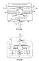
- FIGS. 5A and 5B represent an alternative embodiment of a relay station in which the radio frequency physical layer 10 is common to the two radio modules and is arranged between the switch 8 and the antenna 7.
- the baseband signal emitted by one of the physical layers passes through a switch 8 before being transmitted to a physical radio frequency layer 10 which communicates with the antenna 7.
- the control command C C of the switch 8 is transmitted by the MAC layer 3A for example.
- the synchronization signals SYNC and the relayed data REL are exchanged between the MAC layers 3A, 3B of the relay according to the invention.
- the antenna control C P is derived from the antenna commands C A and C B via the switch 9.
- the command C C from a MAC layer makes it possible in particular to choose the active radio module according to the communication. at a given moment.
- the figure 6 schematizes a frame structure that can operate in a multi-channel transmission context (multi-channel relay station).
- the frame structure for multi-channel mode is built on the following principle; when one of the two radios from the relay station receives, the second radio must not issue. In this case, the two radios must be in the same state, either in transmission or in reception.
- the start of the frame of one of the radios is shifted to match the periods of TX and RX and at each hierarchical level change the radio that performs the shift must be changed.
- the indices n, n-1, n + 1 are used to designate the different levels at which the relay stations are located and corresponding to the indices of the levels TL i in the network tree structure.
- the level TL n is chosen to designate a relay station which communicates with a higher level base station TL n-1 , considering the hierarchy tree of the figure 2 , and also with a lower level station or level TL n + 1 .
- the base station BS and the base station portion of the relay stations RS act as masters in the subnet associated with them (formed with stations of lower hierarchical level). They transmit a synchronization pattern (not shown for reasons of simplification of figure) to their nodes of the slave network in order to temporally synchronize the frames.
- the global synchronization of the network is obtained by a synchronization (at the level of the MAC layer) of the two parts of the relay station; RS (SS) and RS (BS). It can be performed by sending a synchronization pattern from the RS (SS) part to the RS (BS) part in a relay station at the beginning of one of the periods (RX or TX).
- the different subnetworks (a BS or RS (BS) associated with one or more SS or RS (SS)) must use different channels in order to avoid interference between subnetworks. It is possible to implement spatial reuse mechanisms, in particular thanks to the directivity provided by smart antennas, known to those skilled in the art and which will therefore not be detailed.
- the figure 7 schematizes another frame structure that can be used, this time, in a single-channel transmission context (relay station in single-channel mode).
- the ratings of the figure 6 are included for the corresponding elements or modules.
- the frames are divided into 4 parts, symbolized by the periods T 3 , T 4 , T 5 and T 6 on the figure 7 . Note that, in a relay station, the beginning of the lower hierarchical level frame is shifted so as to match the end of the period T 3 with the beginning of the period T 4 .
- the process proceeds from as follows: in the first period RX (time slot T 3 ), the SS part of the relay station RS n receives information or data flow F 5 from the base station BS n-1 or from the relay station RS n -1 of a higher level, during this time, the RS n (BS) part of the relay station is at rest.
- the RS n (BS) of the relay station which will emit information or data flow F 6 to one or more subscriber station (s) (s) ) or RS n + 1 .
- a TX / RX switch allows the same party, the RS n (BS), to receive data F 7 transmitted from the lower hierarchical level n + 1.
- the RS n (SS) portion of the RS may transmit information F 8 to the higher level base station n-1.
- the synchronization between the two radio modules can be obtained by transmitting a synchronization pattern of the RS n (SS) part to the RS n (BS) part at the end of the first RX period, corresponding for example to the beginning of a frame 802.16 (Preamble Issue) in the context of WiMAX.
- SS RS n
- BS RS n
- a "multi-frame" structure is implemented.
- two subnets with consecutive hierarchical levels use the same frame, so an additional frame is used for two other subnets using lower hierarchical levels.
- the sub-networks BS 0 / RS 1 (SS) and RS 1 (BS) / RS 2 (SS) use the frame t while the sub-networks RS 2 (BS) / RS 3 (SS) and RS 3 (BS) / SS 4 use the frame t + 1.
- the RS n (SS) portion of the relay station receives information or data flow F 9 from the radio station. base or relay of a higher level, during this time, the RS n (BS) part of the relay station is at rest.
- time slot T 8 it is still the RS n (SS) portion of the relay station that is in operation. On the other hand this time it will emit information F 10 to the higher level station. Then this part of the RS is at rest, while the subscriber station part is active. Firstly it has the possibility of transmitting F 11 fluxes to the lower level in the period T 9 , and then receiving, in the period T 10 , fluxes F 12 also coming from the lower level.
- the synchronization between the two stations can be obtained by transmitting a synchronization pattern of the SS part to the part BS of the relay station at the end of the period T 8 , corresponding for example to the beginning of a frame 802.16 (emission of the preamble ) in the context of WiMAX.
- This solution allows a simpler hardware implementation.
- This organization can be extended to networks using multiple relay stations (number of subnets greater than two), simply by allocating a consecutive RX period and TX period to each subnet.
- RX and TX two communication periods dedicated to this subnet. This allocation must be offset from other allocations to avoid interference between subnets.
- the Figure 9A shows an example of a frame structure in which the network comprises two relay stations.
- the arrows F correspond to the information flows exchanged between the stations of different hierarchy level.
- the gray arrows correspond to the beginning of a new period as in the Figure 9A .
- the allocation management algorithms are based on identifiers assigned to the base station and each relay station.
- the base station is always associated with the identifier 0, and each relay station is attached to an identifier assigned to it according to its placement in the tree topology, more exactly, it is linked to the hierarchical level (TL i ).
- the objective is that a hierarchical level station has a higher identifier than the higher level stations (nx) and an identifier lower than stations of lower hierarchical level (n + x), x being the number of levels separating the stations.
- the invention provides two modes of allocation management; a static mode and a dynamic mode.
- a simple algorithm can be implemented to manage the allocations made in the frame.
- the relay stations that must be deployed are known initially and their identifiers are assigned during their configuration.
- Each base station and relay station has the same bandwidth corresponding to the division of the available resources by the number of relay stations, incremented by one unit.
- An example of a frame structure is presented on the figure 9 , in which the periods T 11 , T 12 and T 13 would be equal to a period T.
- the base station as well as the "base station" parts of each RS determine the beginning of their period based on the allocated identifier at the node.
- the offset from the beginning of the frame for a BS or RS station (BS) having the identifier y corresponds to the multiplication of this identifier by the period T. Consequently, the base station of the network always starts at the beginning of the frame.
- This algorithm can be used when the base station and relay stations are fixed.
- the dynamic mode makes it possible to take into account the topology modifications that may occur during the operation of the network in the management of the resources of the system.
- the "subscriber station" part scans the predefined channel and tries to associate with the station whose synchronization pattern (preamble, beacon, etc.) corresponds to the best quality. of signal.
- the association procedure consists for example in a synchronization and a data exchange among which the resource allocation information for the part BS of the same relay station; the beginning of the allowance and the duration of this allowance.
- the RS n (SS) can transmit a synchronization pattern Ts to the "base station" part RS n (BS) of this same relay station at the end of the first period RX.
- This synchronization pattern is transmitted at the time corresponding to the beginning of the allocation granted to the RS n (BS) part and must also contain information such as, for example, the duration of the allocation period for the sub-network managed by this RS (BS).
- BS the base station of the network which determines the allocations according to the requests transmitted by the different relay stations. To do this, messages are sent periodically (with a predetermined period) by all relay stations to the base station.
- the "base station” parts of each RS evaluate their bandwidth requirement and transmit this information to the corresponding "subscriber station” part accompanied by additions such as, for example, a priority index. All this information is then transmitted to the BS in the periodic message. If the BS does not receive a certain number of consecutive messages from a RS, then it considers it to be disassociated.
- the identifiers can be modified when a relay station enters or leaves the network (faults, unfavorable environment, etc.).
- the base station informs all the RS of the network so that they take into account a possible modification of their identifier.
- the relay station is not directly linked to the base station of the network, then the information exchanged between these two nodes must be relayed by the intermediate RS. Data from lower level stations can be merged by a relay station into the same message for the BS.
- WiMAX systems support procedures for the entry and registration of a new subscriber station in the network.
- the overall initialization procedure can be divided into several phases, including the channel scan for the downlink, the synchronization, a procedure to perform measurements on the radio channel (more known as "ranging"), trading for basic capabilities and configuring connections.
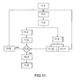
- the algorithm is initialized 11.0 and a timer is initialized 11.1.
- the subscriber station or the SS part of a relay station RS scans the available channels and beam positions, for example according to a procedure where the measurements are taken in turn according to a predefined order or so-called round robin procedure.
- the scan time Tscan is relative to the number of available channels Nchannels and the number of beams that can be used by the Nbeams antenna.
- the procedure for scanning a node equipped with an intelligent antenna consists in searching for the preamble of the start of the frame transmitted by the upper level station step 11.2.
- a beam of the smart antenna is selected randomly so as to start the initialization. Measurements are made for each beam and the duration of the evolution of an antenna beam specifically depends on the scan time called "scan timer" called T20 in the IEEE 802.16-2004 procedure, which corresponds to a duration of 2 * Tframe.
- the modem of the communication system can memorize the measurements made in order to offer different metrics for selecting the beam available for the operation.
- metrics are divided into two subgroups of measures, the first group is the measurement of the signal strength "SSM” or in English signal strength metric and the second group the measurement of the quality of the signal or " SQM "for signal quality metric.
- the CPU can also store various parameters associated with each measurement such as the beam orientation, the address of the associated station. By comparing the different values of SSM and SQM, the receiver module can determine the best beam orientation for the incident signal.
- the procedure requires no modification compared to the synchronization algorithm of a conventional Point-MultiPoint WiMAX system (PMP) until the node is synchronized.
- PMP Point-MultiPoint WiMAX system
- the station if it is a relay station, it will then start transmitting the messages for the downlinks (preamble, FCH and first downward burst) to the lower hierarchical level. This operation is performed according to the structure of the frame envisaged for the relay station.
- Mobility management in the proposed system is performed as follows.
- a set of measurements are carried out continuously and stored at each reception of packets in all the stations. They are based on the two aforementioned metrics: signal strength and signal quality. The average values of these two values are calculated on a number of measurements which is defined according to the environment and the estimated traveling speed for the mobile stations.
- the station will compare the obtained metric to predetermined threshold values.
- These parameters (measured metric) must be determined in a sufficiently precise way to distinguish propagation changes (eg a new obstacle), mainly associated with changes in the received signal strength and changes in arrival angles that impact both metrics.
- propagation changes eg a new obstacle
- the power level alone should be adjusted, whereas when the two SSM and SQM metrics decrease and fall below the predetermined threshold values, the blind pursuit procedure must be implemented.
- the station or its close neighbors will move in a direction that has a component perpendicular to the direction of arrival or DOA.
- the degradation of the state of the link simply requires a power adjustment and not a change of direction of the antenna.
- the proposed tracking method has the advantage of not affecting the behavior of the network because it relies on the use of a transmission slot dedicated to the implementation of measurements. Indeed, a blind procedure for managing the mobility of the nodes of the network, requires to perform measurements with different pointing directions of the beam of the antenna. Such a modification may have an impact on the synchronization if it is performed during the transmission of the synchronization pattern and may also be the cause of a loss of a packet when it is carried out during transmission.
- the figure 12 schematizes an example of a procedure implemented for mobility management in WiMAX systems.
- the proposed procedure is based on the use of the periodic "ranging" procedure which is included in the WiMAX standards.
- the Ranging is a procedure that allows SS and BS stations to maintain a quality of the radio communication link between them.
- the implementation of the tracking procedure in the "ranging" period does not cause any disturbances to the operation of the network because the ranging messages are only associated with measurements. Consequently, the loss of one or more ranging packets during tests performed on the antenna (change of direction of the beam), does not entail any loss of synchronization, or increase of the error rate on the data packets.
- An SS or RS (SS) expects steps 12.0 and 12.1 in the first time the ranging period in the frame, then changes step 12.2 the direction of the beam and sends a ranging request message (RNG-REQ) 12.3 to the station. higher level. If no response to the message is received at this station, the process returns to step 12.1. In the opposite case, a response is received step 12.5 and the node performs measurements on the message transmitted in response by the higher level station (RNG-RSP). This procedure is performed for one or more beams of the antenna so that the measurements can be compared. The resulting metrics are stored 12.6 and if the measured value for each of the two metrics is higher than the value of the predetermined threshold levels, 12.7 then the beam selection is successful and the tracking procedure is completed 12.7.
- the method tests 12.8 if all the beams have been tested. If yes, then there is initialization of the beam 12.9 and if not, the process returns to the step 12.1.
- the initialization of the beam means that the beam associated with the best signal quality is selected and subsequently used for the operation of the relay station when the intelligent antenna is in directional mode. It may be that no beam is available to meet the required signal quality and signal strength levels, in which case the beam used before the procedure is selected and the tracking process is stopped.
- the figure 13 describes the different steps performed during the procedure used by a base station BS or the "base station” part of an RS relay station (BS) is close to that which is implemented in the SS and RS stations (SS ).
- a station initiates a 13.0 tracking procedure, it waits for the next "ranging" period in frame 13.1, then changes antenna mode to use the omni-directional capabilities of the smart antenna.
- the station receives a message from a lower hierarchical station, identified as needing to be followed (“tracking" procedure), then it issues a response (RNG-RSP) requesting retransmission of this message 13.3. Then it goes into directional mode implementing one of the directional beams and waits to receive the message in question 13.4.
- RNG-RSP response
- the station tests whether it receives the message. If the station does not receive the message then it goes into state 13.1. Otherwise, the station performs the signal quality measurements on the received packet 13.6 and then changes the antenna mode 13.7 to omnidirectional operation and thus to communicate with other lower level stations in the ranging period.
- beam selection in the above procedures is not random or done in a round robin fashion. It takes into account the mobility behavior that has been observed during the previous measurements. This is based on beam indices, presented on the figure 13 .
- an index k is associated with a selected beam before the tracking procedure while the other available beams correspond to an index in relation to k.
- a scan direction is determined, based on the stored measurements, allowing a station to be aware of the mobility trend. Any beams that may be available in the scanning direction will receive an index k incremented by the number of beams that separates it from the initial beam, the index including the relevant beam (k-1, k-2, etc.). about half of the beams are located in the scanning direction.
- a target index is identified by the stored measurements. This target index is related to the theoretical direction that should be used if the network behavior had not been changed.
- the method and the relay station according to the invention notably offer the advantages listed below.
Claims (10)
- Relaisstation RS, die in einem Kommunikationsnetz mit einer Baumarchitektur verwendet wird, die aus mehreren Hierarchieebenen TLi gebildet ist, wobei das Kommunikationsnetz eine Zentralstelle wie z.B. die Basisstation BS0 der höchsten Hierarchieebene, eine oder mehrere Relaisstationen RSi und eine oder mehrere Teilnehmerstationen SSi umfasst, dadurch gekennzeichnet, dass eine Relaisstation RSn wenigstens zwei Funkmodule (2A, 2B) umfasst, wobei ein erstes Funkmodul (2A) zum Kommunizieren mit Stationen der unteren Hierarchieebene TL(n+1) ausgelegt ist und ein zweites Funkmodul (2B) zum Kommunizieren mit Stationen der oberen Hierarchieebene TL(n-1) ausgelegt ist, wobei RS zwei verschiedene Frequenzen für Kommunikationen in der unteren Hierarchieebene TL(n+1) und in der oberen Hierarchieebene TL(n-1) benutzt, wobei die beiden Funkmodule (2A, 2B) in der Ebene ihrer MAC-Schicht synchronisiert sind und die Relaisstation wenigstens eine Antenne (6A, 6B, 7) umfasst, die mit der MAC-Schicht der Funkmodule verbunden ist.
- Relaisstation nach Anspruch 1, dadurch gekennzeichnet, dass die Relaisstation RSn eine einzige Antenne (7) umfasst, und dadurch, dass ein Funkmodul (2A, 2B) von einer physischen Basisbandschicht (4A, 4B), einer physischen Funkfrequenzschicht (5A, 5B) und einer MAC-Schicht (3A, 3B) gebildet wird, und dadurch, dass die Relaisstation einen Schalter (8) umfasst, der Funkfrequenzsignale RF der physischen Schicht jedes der Module und auch von der Antenne (7) empfängt, wobei ein Schalter (9) die von der MAC-Schicht kommenden Befehle empfängt und mit der Antenne verbunden ist.
- Relaisstation nach Anspruch 2, dadurch gekennzeichnet, dass sie eine den beiden Funkmodulen gemeinsame physische RF-Schicht (5A, 5B) umfasst, wobei die physische Funkfrequenzschicht (5A, 5B) zwischen dem Schalter (8) und der Antenne platziert ist.
- Relaisstation nach Anspruch 1, dadurch gekennzeichnet, dass der die zu übertragenden Informationen oder Daten enthaltende Frame aus zwei Teilen besteht, die einer Empfangsperiode RX und einer Sendeperiode TX entsprechen, und dadurch, dass die Sendesequenz wie folgt lautet:- in der Periode RX, die dem Zeitschlitz T1 entspricht, empfängt der "Anschlussstation" Teil der Relaisstation RSn(SS) einen Datenfluss F1 von der Station der oberen Ebene (Abwärtsfluss), BSn-1 oder RSn-1(BS), und der "Basisstation" Teil dieser Relaisstation RSn(BS) empfängt einen Datenfluss F2 von einer oder mehreren Anschlussstationen SSn+1 oder RSn+1(SS) der oberen Hierarchieebene (Aufwärtsfluss),- in der Periode TX, die dem Zeitschlitz T2 entspricht, sendet der "Anschlussstation" Teil der Relaisstation RSn(SS) Daten F3 zur Station der oberen Ebene (Aufwärtsfluss), BSn-1 oder RSn-1(BS), und der "Basisstation" Teil dieser Relaisstation RSn(BS) sendet Daten F4 zu einer oder mehreren Stationen der unteren Hierarchieebene (Abwärtsfluss).
- Relaisstation nach einem der Ansprüche 1 bis 3, dadurch gekennzeichnet, dass der die zu sendenden Informationen oder Daten enthaltende Frame aus zwei Teilen besteht, die einer Empfangsperiode RX und einer Sendeperiode TX entsprechen, und dadurch, dass die Sendesequenz wie folgt lautet:- in der ersten Periode RX (Zeitschlitz T3) empfängt der Teil SS der Relaisstation RSn(SS) einen Datenfluss F5 der Station der oberen Ebene, während dieser Zeit ist der Teil BS der Relaisstation RSn(BS) im Ruhezustand,- in der ersten Periode TX, die dem Zeitschlitz T4 entspricht, sendet der Teil BS der Relaisstation RSn(BS) einen Datenfluss F6 zu einer oder mehreren Stationen der unteren Ebene, dann lässt es eine TX/RX-Schaltung zu, dass derselbe Teil, RSn(BS), einen von der unteren Hierarchieebene gesendeten Datenfluss F7 empfängt,- in der zweiten Periode TX, Zeitschlitz T6, sendet der Teil SS der RSn einen Datenfluss F8 zur Station der oberen Ebene BSn+1 oder RSn+1(BS).
- Relaisstation nach einem der Ansprüche 1 bis 3, dadurch gekennzeichnet, dass der die zu sendenden Informationen oder Daten enthaltende Frame aus zwei Teilen besteht, die einer Empfangsperiode RX und einer Sendeperiode TX entsprechen, und dadurch, dass die Sendefolge wie folgt lautet:- in der ersten Periode RX, Zeitschlitz T7, empfängt der Teil SS der Relaisstation RSn(SS) einen Datenfluss F9 von der Station der oberen Ebene n+1, während dieser Zeit ist der Teil BS der Relaisstation RSn(BS) im Ruhezustand,- im ersten Teil der Periode TX, Zeitschlitz T8, sendet der Teil BS der Relaisstation RSn(BS) einen Datenfluss F10 zur Station der oberen Ebene n+1, dann lässt es eine TX/RX-Schaltung zu, dass der Teil SS der Relaisstation RSn(SS) im Zeitschlitz T9 der Periode TX zu einer oder mehreren Stationen der unteren Hierarchieebene n-1 sendet, dann empfängt dieser selbe Teil im Zeitschlitz T10 der Periode RX einen Datenfluss F12, der von einer oder mehreren Stationen der unteren Hierarchieebene n-1 kommt.
- Relaisstation nach Anspruch 6, dadurch gekennzeichnet, dass der Frame in einem Zweig gleichzeitige Sendungen in den Ebenen n und n+2 zulässt, nämlich z.B. zwischen BSn+2 und SSn+3 einerseits und BSn und SSn+1 andererseits.
- Relaisstation nach einem der Ansprüche 1 bis 6, dadurch gekennzeichnet, dass die Synchronisation durch Senden eines Synchronisationsmusters Ts vom Teilnehmerstationsteil RSn(SS) zum Basisstationsteil RSn(BS) am Ende der ersten Periode RX erfolgt.
- Relaisstation nach einem der Ansprüche 1 bis 8, dadurch gekennzeichnet, dass die Weitersendung von Daten-, Steuer- und Managementpaketen in Ebene zwei des OSI-Protokollstapels unter Herstellung einer Verbindung zwischen den beiden MAC-Schichten von zwei Funkmodulen derselben Station erfolgt.
- Relaisstation nach einem der Ansprüche 1 bis 9, dadurch gekennzeichnet, dass die die Relaisstation ausstattende Antenne eine intelligente Antenne mit Schnellumschaltung des Typs FESA ist.
Applications Claiming Priority (2)
| Application Number | Priority Date | Filing Date | Title |
|---|---|---|---|
| FR0801869A FR2929781B1 (fr) | 2008-04-04 | 2008-04-04 | Station relais a double radio. |
| PCT/EP2009/053311 WO2009121730A1 (fr) | 2008-04-04 | 2009-03-20 | Station relais a double radio |
Publications (2)
| Publication Number | Publication Date |
|---|---|
| EP2260655A1 EP2260655A1 (de) | 2010-12-15 |
| EP2260655B1 true EP2260655B1 (de) | 2014-06-04 |
Family
ID=40184946
Family Applications (1)
| Application Number | Title | Priority Date | Filing Date |
|---|---|---|---|
| EP09726487.3A Active EP2260655B1 (de) | 2008-04-04 | 2009-03-20 | Doppelte funkrelaisstation |
Country Status (5)
| Country | Link |
|---|---|
| US (1) | US20110051656A1 (de) |
| EP (1) | EP2260655B1 (de) |
| ES (1) | ES2485640T3 (de) |
| FR (1) | FR2929781B1 (de) |
| WO (1) | WO2009121730A1 (de) |
Families Citing this family (13)
| Publication number | Priority date | Publication date | Assignee | Title |
|---|---|---|---|---|
| KR101339477B1 (ko) * | 2009-08-31 | 2013-12-10 | 엘지전자 주식회사 | 다중 반송파 시스템에서 중계국의 단위 반송파 이용 방법 및 중계국 |
| US9191098B2 (en) * | 2011-01-14 | 2015-11-17 | Telefonaktiebolaget L M Ericsson (Publ) | Capability reporting for relay nodes in wireless networks |
| FR2974264B1 (fr) | 2011-04-14 | 2014-01-17 | Thales Sa | Station emettrice/receptrice pour former un noeud d'un reseau de telecommunication et procede de telecommunication associe |
| KR102028495B1 (ko) * | 2012-01-16 | 2019-10-04 | 한국전자통신연구원 | 센서 네트워크 및 센서 네트워크에서 타임 슬롯 중계 기반의 링크 확장 방법 |
| US9301246B2 (en) * | 2012-01-16 | 2016-03-29 | Electronics And Telecommunications Research Institute | Sensor network and method of link extension based on time slot relaying in the same |
| US9535680B2 (en) * | 2013-03-12 | 2017-01-03 | Broadcom Corporation | Flashless optical network unit |
| US9485797B2 (en) * | 2013-06-20 | 2016-11-01 | Electronics And Telecommunications Research Institute | Method and apparatus for device-to-device direct communication |
| US9851982B2 (en) * | 2014-02-28 | 2017-12-26 | Tyco Fire & Security Gmbh | Emergency video camera system |
| US10878323B2 (en) | 2014-02-28 | 2020-12-29 | Tyco Fire & Security Gmbh | Rules engine combined with message routing |
| US10050865B2 (en) | 2014-02-28 | 2018-08-14 | Tyco Fire & Security Gmbh | Maintaining routing information |
| US20150288604A1 (en) * | 2014-04-02 | 2015-10-08 | Tyco Fire & Security Gmbh | Sensor Network Gateway |
| US9280389B1 (en) | 2014-12-30 | 2016-03-08 | Tyco Fire & Security Gmbh | Preemptive operating system without context switching |
| US10420018B2 (en) * | 2016-11-23 | 2019-09-17 | Qualcomm Incorporated | Steady-state beam scanning and codebook generation |
Family Cites Families (8)
| Publication number | Priority date | Publication date | Assignee | Title |
|---|---|---|---|---|
| US7366089B2 (en) * | 2003-10-08 | 2008-04-29 | Atheros Communications, Inc. | Apparatus and method of multiple antenna receiver combining of high data rate wideband packetized wireless communication signals |
| FR2861231A1 (fr) * | 2003-10-20 | 2005-04-22 | Thomson Licensing Sa | Methode de communication dans un reseau de communication sans fil |
| CN101106807B (zh) * | 2006-07-12 | 2012-04-11 | 株式会社Ntt都科摩 | 一种基于中继器的蜂窝网络以及空分双工通信方法 |
| JP5034369B2 (ja) * | 2006-08-18 | 2012-09-26 | 富士通株式会社 | 無線通信制御方法 |
| US20080068979A1 (en) * | 2006-09-14 | 2008-03-20 | Motorola, Inc. | Adaptive and preemptive scheduling of transmissions |
| US20080107063A1 (en) * | 2006-11-03 | 2008-05-08 | Fujitsu Limited | Bandwidth reuse in a multi-hop mobile relay system |
| US8717965B2 (en) * | 2006-12-01 | 2014-05-06 | Apple Inc. | Enhancing wimax performance with subscriber stations acting as ad hoc repeaters |
| US20090203310A1 (en) * | 2008-02-12 | 2009-08-13 | Lucent Technologies Inc. | Superposition transmission and detection of access and backhaul signals |
-
2008
- 2008-04-04 FR FR0801869A patent/FR2929781B1/fr active Active
-
2009
- 2009-03-20 ES ES09726487.3T patent/ES2485640T3/es active Active
- 2009-03-20 EP EP09726487.3A patent/EP2260655B1/de active Active
- 2009-03-20 WO PCT/EP2009/053311 patent/WO2009121730A1/fr active Application Filing
- 2009-03-20 US US12/936,223 patent/US20110051656A1/en not_active Abandoned
Also Published As
| Publication number | Publication date |
|---|---|
| EP2260655A1 (de) | 2010-12-15 |
| FR2929781B1 (fr) | 2011-09-02 |
| ES2485640T3 (es) | 2014-08-14 |
| US20110051656A1 (en) | 2011-03-03 |
| WO2009121730A1 (fr) | 2009-10-08 |
| FR2929781A1 (fr) | 2009-10-09 |
Similar Documents
| Publication | Publication Date | Title |
|---|---|---|
| EP2260655B1 (de) | Doppelte funkrelaisstation | |
| EP1936872B1 (de) | Flexibles Funknetzwerk | |
| EP2512201B1 (de) | Sende/empfangsstation und verfahren zur Herstellung eines Telekommunikationsnetzknotens | |
| EP3607673B1 (de) | Verfahren und system zum transportieren von signalen in einem satellitensystem | |
| FR2922064A1 (fr) | Procede de pilotage d'antennes intelligentes au sein d'un reseau de communication | |
| CA2769537C (fr) | Methode d'acces multiple aux ressources radio dans un reseau ad hoc mobile et systeme mettant en oeuvre la methode | |
| EP3329702B1 (de) | Verfahren zur knotenerkennung in einem ad-hoc-netzwerk | |
| EP3104534A1 (de) | Verfahren zur lokalen korrektur des routingwegs in einem ad-hoc-netz, und entsprechendes ad-hoc-netz | |
| EP3516794B1 (de) | Verfahren zur unterscheidung von uplink- oder downlink-kommunikation | |
| CA2374339C (fr) | Procede de radiocommunication entre une station de base et des terminaux mobiles | |
| EP0767550B1 (de) | Interbandfrequenzsprungverfahren in einer zellulare Funkkommunikationsanordnung mit mobilen Stationen und Stationen dafür | |
| FR2932627A1 (fr) | Terminal mobile d'un systeme de communication par onde radiofrequence de type dect et procede de gestion des antennes de ce terminal | |
| EP3100519B1 (de) | In ein funkkommunikationsnetzwerk implementiertes relaisverfahren und endgerät zur implementierung des besagten verfahrens | |
| EP3675581A1 (de) | Herstellung einer verbindung zum datenaustausch unter ip-protokoll zwischen basisstationen von mobilstrukturen mit unterteilung des frequenzbands in frequenzteilbänder | |
| FR3091450A1 (fr) | Etablissement d’une liaison d’échange de données sous protocole IP entre des stations de base améliorées par communication directe | |
| EP3675546A1 (de) | Funkscanner an bord einer mobilen struktur eines funkkommunikationssystems, und verfahren zu ihrer verwendung | |
| FR3091437A1 (fr) | Scanner radio embarqué dans une structure mobile d’un système de radiocommunications | |
| FR2983376A1 (fr) | Procede de synchronisation de sous reseaux hierarchises | |
| FR2820257A1 (fr) | Systeme radio haute capacite |
Legal Events
| Date | Code | Title | Description |
|---|---|---|---|
| PUAI | Public reference made under article 153(3) epc to a published international application that has entered the european phase |
Free format text: ORIGINAL CODE: 0009012 |
|
| 17P | Request for examination filed |
Effective date: 20101012 |
|
| AK | Designated contracting states |
Kind code of ref document: A1 Designated state(s): AT BE BG CH CY CZ DE DK EE ES FI FR GB GR HR HU IE IS IT LI LT LU LV MC MK MT NL NO PL PT RO SE SI SK TR |
|
| AX | Request for extension of the european patent |
Extension state: AL BA RS |
|
| 17Q | First examination report despatched |
Effective date: 20110302 |
|
| DAX | Request for extension of the european patent (deleted) | ||
| REG | Reference to a national code |
Ref country code: DE Ref legal event code: R079 Ref document number: 602009024438 Country of ref document: DE Free format text: PREVIOUS MAIN CLASS: H04W0016260000 Ipc: H04B0007260000 |
|
| RIC1 | Information provided on ipc code assigned before grant |
Ipc: H04B 7/155 20060101ALI20130108BHEP Ipc: H04B 7/26 20060101AFI20130108BHEP |
|
| GRAP | Despatch of communication of intention to grant a patent |
Free format text: ORIGINAL CODE: EPIDOSNIGR1 |
|
| INTG | Intention to grant announced |
Effective date: 20140127 |
|
| GRAS | Grant fee paid |
Free format text: ORIGINAL CODE: EPIDOSNIGR3 |
|
| GRAA | (expected) grant |
Free format text: ORIGINAL CODE: 0009210 |
|
| AK | Designated contracting states |
Kind code of ref document: B1 Designated state(s): AT BE BG CH CY CZ DE DK EE ES FI FR GB GR HR HU IE IS IT LI LT LU LV MC MK MT NL NO PL PT RO SE SI SK TR |
|
| REG | Reference to a national code |
Ref country code: GB Ref legal event code: FG4D Free format text: NOT ENGLISH |
|
| REG | Reference to a national code |
Ref country code: CH Ref legal event code: EP |
|
| REG | Reference to a national code |
Ref country code: AT Ref legal event code: REF Ref document number: 671603 Country of ref document: AT Kind code of ref document: T Effective date: 20140615 |
|
| REG | Reference to a national code |
Ref country code: IE Ref legal event code: FG4D Free format text: LANGUAGE OF EP DOCUMENT: FRENCH |
|
| REG | Reference to a national code |
Ref country code: DE Ref legal event code: R096 Ref document number: 602009024438 Country of ref document: DE Effective date: 20140717 |
|
| REG | Reference to a national code |
Ref country code: ES Ref legal event code: FG2A Ref document number: 2485640 Country of ref document: ES Kind code of ref document: T3 Effective date: 20140814 |
|
| REG | Reference to a national code |
Ref country code: NL Ref legal event code: T3 |
|
| REG | Reference to a national code |
Ref country code: AT Ref legal event code: MK05 Ref document number: 671603 Country of ref document: AT Kind code of ref document: T Effective date: 20140604 |
|
| PG25 | Lapsed in a contracting state [announced via postgrant information from national office to epo] |
Ref country code: CY Free format text: LAPSE BECAUSE OF FAILURE TO SUBMIT A TRANSLATION OF THE DESCRIPTION OR TO PAY THE FEE WITHIN THE PRESCRIBED TIME-LIMIT Effective date: 20140604 Ref country code: NO Free format text: LAPSE BECAUSE OF FAILURE TO SUBMIT A TRANSLATION OF THE DESCRIPTION OR TO PAY THE FEE WITHIN THE PRESCRIBED TIME-LIMIT Effective date: 20140904 Ref country code: GR Free format text: LAPSE BECAUSE OF FAILURE TO SUBMIT A TRANSLATION OF THE DESCRIPTION OR TO PAY THE FEE WITHIN THE PRESCRIBED TIME-LIMIT Effective date: 20140905 Ref country code: FI Free format text: LAPSE BECAUSE OF FAILURE TO SUBMIT A TRANSLATION OF THE DESCRIPTION OR TO PAY THE FEE WITHIN THE PRESCRIBED TIME-LIMIT Effective date: 20140604 Ref country code: LT Free format text: LAPSE BECAUSE OF FAILURE TO SUBMIT A TRANSLATION OF THE DESCRIPTION OR TO PAY THE FEE WITHIN THE PRESCRIBED TIME-LIMIT Effective date: 20140604 |
|
| REG | Reference to a national code |
Ref country code: LT Ref legal event code: MG4D |
|
| PG25 | Lapsed in a contracting state [announced via postgrant information from national office to epo] |
Ref country code: AT Free format text: LAPSE BECAUSE OF FAILURE TO SUBMIT A TRANSLATION OF THE DESCRIPTION OR TO PAY THE FEE WITHIN THE PRESCRIBED TIME-LIMIT Effective date: 20140604 Ref country code: SE Free format text: LAPSE BECAUSE OF FAILURE TO SUBMIT A TRANSLATION OF THE DESCRIPTION OR TO PAY THE FEE WITHIN THE PRESCRIBED TIME-LIMIT Effective date: 20140604 Ref country code: LV Free format text: LAPSE BECAUSE OF FAILURE TO SUBMIT A TRANSLATION OF THE DESCRIPTION OR TO PAY THE FEE WITHIN THE PRESCRIBED TIME-LIMIT Effective date: 20140604 Ref country code: HR Free format text: LAPSE BECAUSE OF FAILURE TO SUBMIT A TRANSLATION OF THE DESCRIPTION OR TO PAY THE FEE WITHIN THE PRESCRIBED TIME-LIMIT Effective date: 20140604 |
|
| PG25 | Lapsed in a contracting state [announced via postgrant information from national office to epo] |
Ref country code: SK Free format text: LAPSE BECAUSE OF FAILURE TO SUBMIT A TRANSLATION OF THE DESCRIPTION OR TO PAY THE FEE WITHIN THE PRESCRIBED TIME-LIMIT Effective date: 20140604 Ref country code: PT Free format text: LAPSE BECAUSE OF FAILURE TO SUBMIT A TRANSLATION OF THE DESCRIPTION OR TO PAY THE FEE WITHIN THE PRESCRIBED TIME-LIMIT Effective date: 20141006 Ref country code: RO Free format text: LAPSE BECAUSE OF FAILURE TO SUBMIT A TRANSLATION OF THE DESCRIPTION OR TO PAY THE FEE WITHIN THE PRESCRIBED TIME-LIMIT Effective date: 20140604 Ref country code: CZ Free format text: LAPSE BECAUSE OF FAILURE TO SUBMIT A TRANSLATION OF THE DESCRIPTION OR TO PAY THE FEE WITHIN THE PRESCRIBED TIME-LIMIT Effective date: 20140604 Ref country code: EE Free format text: LAPSE BECAUSE OF FAILURE TO SUBMIT A TRANSLATION OF THE DESCRIPTION OR TO PAY THE FEE WITHIN THE PRESCRIBED TIME-LIMIT Effective date: 20140604 |
|
| PG25 | Lapsed in a contracting state [announced via postgrant information from national office to epo] |
Ref country code: PL Free format text: LAPSE BECAUSE OF FAILURE TO SUBMIT A TRANSLATION OF THE DESCRIPTION OR TO PAY THE FEE WITHIN THE PRESCRIBED TIME-LIMIT Effective date: 20140604 Ref country code: IS Free format text: LAPSE BECAUSE OF FAILURE TO SUBMIT A TRANSLATION OF THE DESCRIPTION OR TO PAY THE FEE WITHIN THE PRESCRIBED TIME-LIMIT Effective date: 20141004 |
|
| REG | Reference to a national code |
Ref country code: DE Ref legal event code: R097 Ref document number: 602009024438 Country of ref document: DE |
|
| PLBE | No opposition filed within time limit |
Free format text: ORIGINAL CODE: 0009261 |
|
| STAA | Information on the status of an ep patent application or granted ep patent |
Free format text: STATUS: NO OPPOSITION FILED WITHIN TIME LIMIT |
|
| PG25 | Lapsed in a contracting state [announced via postgrant information from national office to epo] |
Ref country code: IT Free format text: LAPSE BECAUSE OF FAILURE TO SUBMIT A TRANSLATION OF THE DESCRIPTION OR TO PAY THE FEE WITHIN THE PRESCRIBED TIME-LIMIT Effective date: 20140604 Ref country code: DK Free format text: LAPSE BECAUSE OF FAILURE TO SUBMIT A TRANSLATION OF THE DESCRIPTION OR TO PAY THE FEE WITHIN THE PRESCRIBED TIME-LIMIT Effective date: 20140604 |
|
| 26N | No opposition filed |
Effective date: 20150305 |
|
| REG | Reference to a national code |
Ref country code: DE Ref legal event code: R097 Ref document number: 602009024438 Country of ref document: DE Effective date: 20150305 |
|
| PG25 | Lapsed in a contracting state [announced via postgrant information from national office to epo] |
Ref country code: SI Free format text: LAPSE BECAUSE OF FAILURE TO SUBMIT A TRANSLATION OF THE DESCRIPTION OR TO PAY THE FEE WITHIN THE PRESCRIBED TIME-LIMIT Effective date: 20140604 |
|
| PG25 | Lapsed in a contracting state [announced via postgrant information from national office to epo] |
Ref country code: MC Free format text: LAPSE BECAUSE OF FAILURE TO SUBMIT A TRANSLATION OF THE DESCRIPTION OR TO PAY THE FEE WITHIN THE PRESCRIBED TIME-LIMIT Effective date: 20140604 Ref country code: LU Free format text: LAPSE BECAUSE OF FAILURE TO SUBMIT A TRANSLATION OF THE DESCRIPTION OR TO PAY THE FEE WITHIN THE PRESCRIBED TIME-LIMIT Effective date: 20150320 |
|
| REG | Reference to a national code |
Ref country code: CH Ref legal event code: PL |
|
| REG | Reference to a national code |
Ref country code: IE Ref legal event code: MM4A |
|
| PG25 | Lapsed in a contracting state [announced via postgrant information from national office to epo] |
Ref country code: IE Free format text: LAPSE BECAUSE OF NON-PAYMENT OF DUE FEES Effective date: 20150320 Ref country code: LI Free format text: LAPSE BECAUSE OF NON-PAYMENT OF DUE FEES Effective date: 20150331 Ref country code: CH Free format text: LAPSE BECAUSE OF NON-PAYMENT OF DUE FEES Effective date: 20150331 |
|
| REG | Reference to a national code |
Ref country code: FR Ref legal event code: PLFP Year of fee payment: 8 |
|
| PG25 | Lapsed in a contracting state [announced via postgrant information from national office to epo] |
Ref country code: MT Free format text: LAPSE BECAUSE OF FAILURE TO SUBMIT A TRANSLATION OF THE DESCRIPTION OR TO PAY THE FEE WITHIN THE PRESCRIBED TIME-LIMIT Effective date: 20140604 |
|
| REG | Reference to a national code |
Ref country code: FR Ref legal event code: PLFP Year of fee payment: 9 |
|
| PG25 | Lapsed in a contracting state [announced via postgrant information from national office to epo] |
Ref country code: HU Free format text: LAPSE BECAUSE OF FAILURE TO SUBMIT A TRANSLATION OF THE DESCRIPTION OR TO PAY THE FEE WITHIN THE PRESCRIBED TIME-LIMIT; INVALID AB INITIO Effective date: 20090320 Ref country code: BG Free format text: LAPSE BECAUSE OF FAILURE TO SUBMIT A TRANSLATION OF THE DESCRIPTION OR TO PAY THE FEE WITHIN THE PRESCRIBED TIME-LIMIT Effective date: 20140604 |
|
| PG25 | Lapsed in a contracting state [announced via postgrant information from national office to epo] |
Ref country code: BE Free format text: LAPSE BECAUSE OF NON-PAYMENT OF DUE FEES Effective date: 20150331 |
|
| PG25 | Lapsed in a contracting state [announced via postgrant information from national office to epo] |
Ref country code: TR Free format text: LAPSE BECAUSE OF FAILURE TO SUBMIT A TRANSLATION OF THE DESCRIPTION OR TO PAY THE FEE WITHIN THE PRESCRIBED TIME-LIMIT Effective date: 20140604 |
|
| REG | Reference to a national code |
Ref country code: FR Ref legal event code: PLFP Year of fee payment: 10 |
|
| PG25 | Lapsed in a contracting state [announced via postgrant information from national office to epo] |
Ref country code: MK Free format text: LAPSE BECAUSE OF FAILURE TO SUBMIT A TRANSLATION OF THE DESCRIPTION OR TO PAY THE FEE WITHIN THE PRESCRIBED TIME-LIMIT Effective date: 20140604 |
|
| PGFP | Annual fee paid to national office [announced via postgrant information from national office to epo] |
Ref country code: NL Payment date: 20230224 Year of fee payment: 15 |
|
| PGFP | Annual fee paid to national office [announced via postgrant information from national office to epo] |
Ref country code: FR Payment date: 20230221 Year of fee payment: 15 |
|
| PGFP | Annual fee paid to national office [announced via postgrant information from national office to epo] |
Ref country code: GB Payment date: 20230216 Year of fee payment: 15 Ref country code: DE Payment date: 20230214 Year of fee payment: 15 |
|
| P01 | Opt-out of the competence of the unified patent court (upc) registered |
Effective date: 20230517 |
|
| PGFP | Annual fee paid to national office [announced via postgrant information from national office to epo] |
Ref country code: ES Payment date: 20230405 Year of fee payment: 15 |