EP2259083B1 - Système décorrélé - Google Patents
Système décorrélé Download PDFInfo
- Publication number
- EP2259083B1 EP2259083B1 EP09161975.9A EP09161975A EP2259083B1 EP 2259083 B1 EP2259083 B1 EP 2259083B1 EP 09161975 A EP09161975 A EP 09161975A EP 2259083 B1 EP2259083 B1 EP 2259083B1
- Authority
- EP
- European Patent Office
- Prior art keywords
- wave
- radiation
- devices
- distance
- different
- Prior art date
- Legal status (The legal status is an assumption and is not a legal conclusion. Google has not performed a legal analysis and makes no representation as to the accuracy of the status listed.)
- Active
Links
Images
Classifications
-
- G—PHYSICS
- G01—MEASURING; TESTING
- G01S—RADIO DIRECTION-FINDING; RADIO NAVIGATION; DETERMINING DISTANCE OR VELOCITY BY USE OF RADIO WAVES; LOCATING OR PRESENCE-DETECTING BY USE OF THE REFLECTION OR RERADIATION OF RADIO WAVES; ANALOGOUS ARRANGEMENTS USING OTHER WAVES
- G01S3/00—Direction-finders for determining the direction from which infrasonic, sonic, ultrasonic, or electromagnetic waves, or particle emission, not having a directional significance, are being received
- G01S3/02—Direction-finders for determining the direction from which infrasonic, sonic, ultrasonic, or electromagnetic waves, or particle emission, not having a directional significance, are being received using radio waves
- G01S3/14—Systems for determining direction or deviation from predetermined direction
- G01S3/46—Systems for determining direction or deviation from predetermined direction using antennas spaced apart and measuring phase or time difference between signals therefrom, i.e. path-difference systems
-
- G—PHYSICS
- G01—MEASURING; TESTING
- G01S—RADIO DIRECTION-FINDING; RADIO NAVIGATION; DETERMINING DISTANCE OR VELOCITY BY USE OF RADIO WAVES; LOCATING OR PRESENCE-DETECTING BY USE OF THE REFLECTION OR RERADIATION OF RADIO WAVES; ANALOGOUS ARRANGEMENTS USING OTHER WAVES
- G01S3/00—Direction-finders for determining the direction from which infrasonic, sonic, ultrasonic, or electromagnetic waves, or particle emission, not having a directional significance, are being received
- G01S3/02—Direction-finders for determining the direction from which infrasonic, sonic, ultrasonic, or electromagnetic waves, or particle emission, not having a directional significance, are being received using radio waves
- G01S3/74—Multi-channel systems specially adapted for direction-finding, i.e. having a single antenna system capable of giving simultaneous indications of the directions of different signals
Definitions
- the present invention relates to a method for analyzing directions of incidence of wave portions, in particular electromagnetic, comprising radiating a wave from a radiating device at a first location and receiving the wave components of the shaft irradiated at a second location with at least two reception devices and evaluating the radiated wave components with respect to the direction of arrival.
- Such a method is known, for example from the WO 2007/085517 A1 , It is particularly known to use as receiving device an array of antennas.
- an array of antennas For example, the use of a linear antenna array is known here.
- the direction of incidence of the wave can then be calculated under ideal conditions or determined by special superimposition of the signals of the individual antennas.
- further methods such as MUSIC and / or Capon can be used here.
- the object of the present invention is thus to avoid the disadvantages described and in particular to provide a method, a system and a use which make it possible to determine the direction of incidence of waves even with comparatively little effort, if a broad frequency spectrum is not available ,
- the object of the present invention is thus also to improve the angular resolution to be achieved for a given accuracy of the components used.
- the underlying principle of the different inventive embodiments of the present invention is to use two radiation devices for decorrelation, which are arranged stationary in the radiation relative to a location.
- the inventive idea that underlies this method manifests itself with a corresponding arrangement or choice of emitting devices in that the wave portions arriving at the receiving location are decorrelated by the specific emission and thus can be distinguished and thus an analysis of the directions of incidence also in the case of multipathing Based on the phase differences and / or differences in amplitude of the received signals of the at least two receiving devices is possible.
- the decorrelation can take place on the one hand by the selection of a minimum distance between the first emitting device and the second emitting device or by the use of emitting devices which have different radiation characteristics with respect to the polarization.
- the present object is achieved by a method according to claim 1, by a system according to claim 14, as well as by a use according to claim 15.
- the sub-claims two to thirteen indicate advantageous and further developments, which have partially independent inventive value.
- steps A to D can also be performed in a different order, for example, the blasting of the second wave can be done before wave components of the first wave were received according to step B at the second location.
- the distance between the first and second radiating devices should be small in relation to the distance between the radiating devices and the receiving devices.
- Distance ratios is necessary to ensure a sufficiently small angular divergence at the receiving location to assign the individual Wave components to enable individual propagation paths.
- Klein can mean a ratio of less than one. In more complex environments, however, the ratio will be much smaller, especially on the order of 10 -2 or smaller.
- the distance between the emitting devices does not fall below a minimum distance measured in terms of the resolution capability of the analysis in order to achieve a (measurable) decorrelation at all. The distance must therefore not fall below the (absolute) measurement error with respect to the wavelength in the analysis of the phase difference.
- a minimum distance of at least 3%, in particular at least 5%, of the smallest wavelength used for the analysis has proven to be particularly advantageous. This minimum distance depends on the resolution of the selected components.
- (absolute) measurement error with respect to the wavelength in the analysis of the phase difference is understood to be the length which is obtained by multiplying the absolute phase error in degrees (full circle 360 °) in the analysis of the phase difference with the wavelength of the wave or of the wave component and divided by 360 °.
- the distance between the nearest emitting devices and receiving devices is usually set. However, this can be different if only individual emitting and / or receiving devices from a plurality of emitting and / or receiving devices are closer to each other than the majority of the emitting and / or receiving devices. Decisive is much more that the conditions are observed in the consideration of at least two of the emitting devices and at least two of the receiving devices accordingly.
- the first reception device has slight differences in comparison with the second radiation device incorporating the polarization.
- the emitting devices with different polarization directions be used. This is the case, for example, when using a horizontally polarized antenna and a vertically polarized antenna or when choosing a linearly polarized and a circularly polarized antenna. However, this is also the case if the emitting devices are predominantly horizontal, vertical or circularly polarized.
- the wave components irradiated and reflected on the path at the receiving location by different emission devices are at least partially distinguishable on the basis of the different reflection due to the different polarization on the basis of the phase and / or amplitude. Furthermore, a further improvement can be achieved by analyzing the polarization of the received wave components, in particular when using emission devices with different emission characteristics with respect to the polarization.
- the evaluation of the received signals can be carried out either which directions of incidence have different wave components or are limited to determining the number of different directions of incidence.
- the determination of only a number of different directions of incidence or the number of different directions of incidence represents only a compression of the information material that is or can be obtained when the wave components are separated according to different directions of incidence.
- such an evaluation may include certain limits, according to which only directions are evaluated, from which a certain wave component or a certain signal strength (relatively or absolutely) has occurred.
- only the wave components can be broken down by directions of incidence, which belong to a certain amount of the strongest or weakest signal incidence directions.
- the directions of incidence of the wave components of the first and second wave, which were received via a propagation path are distinguished. It is much more a goal to differentiate the directions of incidence of wave components that have been transmitted via different propagation paths. This means that, for example, the wave components of the first and second waves, which were transmitted directly without reflection (first propagation path), should be distinguished from the wave components of the first and second wave, which were transmitted via the reflection at one plane (two propagation path). , it is also sufficient for the method according to the invention to determine the direction of incidence of the wave components which were received via a propagation path together, that is to say on average, for example.
- the distinction of the propagation paths is carried out using the decorrelation according to the invention. It leads in the wave components received over different propagation paths to differences in phase and / or amplitude and optionally polarization, on the basis of which the wave components which were received via different propagation paths can be distinguished.
- wave components of the first and second wave is based, for example, on the time or sequence or the frequency (when the first wave is emitted with a different frequency / response from the frequency or the frequency spectrum or the frequency response of the second wave). spectrum) possible.
- a signal of a receiving device is to be understood as the signal that arises at a receiving device when a wave component is received. This is usually the measurable at the receiving device voltage waveform.
- the determination of the directions of incidence itself can be carried out, for example, by using autocorrelation matrices of the measured values of the receiving devices and application of array responses. Such methods are known in the art. It can be used on different procedures. So can the Array responses can be calculated as matrices or functions or stored. It is also possible to use multidimensional array responses. Furthermore, further methods, for example MUSIC or Capon, can be used for filtering out noise or interference components. These methods are known in the art.
- the further signal processing can be implemented and adapted to the respective requirement.
- the choice of the corresponding receiving devices and their number as well as the type and number of emitting devices can be adapted by the skilled person to the respective application requirements. It is important to ensure that the desired angular accuracy can be achieved by the components used, in particular for phase analysis.
- the method according to the invention can furthermore be combined with numerous methods from the prior art.
- wave components of the first and second wave which have taken a substantially same signal propagation at the second location, ie at the receiving devices, an angular divergence between the wave portions of the first and the wave portions of second wave of less than ten degrees (full circle 360 °), in particular less than five degrees.
- substantially equal signal propagation paths it is to be understood, for example, that although the wave components were radiated at slightly different positions, they were otherwise reflected at the same planes, but not necessarily at exactly the same points or regions of the planes.
- the angular divergence meets the requirement for the size of the angular divergence only in the case of signal propagation paths which have no reflection or only one or more reflections on flat surfaces. Also, this requirement does not have to be for all such Signal propagation paths apply. Rather, it is sufficient if it is ensured that the requirement for the magnitude of the angular divergence in the selected arrangement is met by wave portions arriving or receivable at the second location, that is to say with sufficient amplitude for the evaluation.
- a planar surface is not only a macroscopically expanded surface. Depending on the waves used and their wavelength, even small planes or approximately flat surfaces are sufficient. Rather, it is decisive that, in a reflection of two waves (fractions) on a flat surface in the sense of the present document, the angular divergence between the wave components before the reflection and after the reflection are approximately identical.
- An arrangement according to claim 2 allows a particularly good assignment of the wave components of the first and the second wave, which have brought a largely identical signal travel path behind. As a result, a particularly reliable or particularly easy to carry out analysis of the directions of incidence is possible. Different angular divergences of waves of two fixed radiators result when the viewing angle on the radiators is changed. This is also the case when looking over a reflective surface on the emitting devices.
- the angular divergence may be minimized by keeping the distance between the first and second radiating devices small relative to the distance between the radiating devices and the receiving devices.
- the person skilled in the art can determine the spacing ratios necessary for certain angular divergences by simple geometrical considerations. This becomes particularly simple if the geometry of the place of use and the arrangement and position (s) of the emitting devices and receiving devices are at least largely known.
- the steps A to D are performed several times according to claim 3.
- preferably more than two emitting devices are used.
- a plurality of emitting devices may be used and the blasting may be performed once with each emitting device.
- it is too it is conceivable to use only a few emitting devices and to emit them several times with each emitting device. Again, it is not necessary that the waves are received before new waves are broadcast. However, doing so can make it more reliable.
- the step F the evaluation of the received signals with respect to the directions of incidence, can also be performed several times or only after all receivable wave components have been received.
- first and second emitting device identical emitting devices and to arrange them at a distance which is greater than the error with respect to the wavelength in the analysis of the phase difference, in particular at least 3% of the smallest wavelength of the first and second wave to be used for the evaluation, in particular more than 5% of this wavelength is.
- Identical emitting devices in this sense are also present if they have deviations within the scope of manufacturing tolerance.
- Such a choice of the emitting devices may be particularly advantageous if it is known which signals are supplied to the emitting devices. Because then can be taken into account in the evaluation that the radiation from the two emitting devices, except for the location shift, was identical.
- a single transmitting device is used as the first and second emitting device, which moves between a first position at the first location to a second position at the first location between steps A and C is, wherein the distance between the first position and the second position is greater than the error with respect to the wavelength in the analysis of the phase differences of the smallest wavelength of the first and second wave and / or the transmitting device is moved so that when performing steps A and C has a different polarization with respect to the polarization.
- a single transmission device between the radiation of the first wave and the second wave is linearly displaced by a linear motor a predetermined distance.
- a transmission device which is linearly polarized for example, to be rotated by 90 degrees and thus to have a different emission characteristic with respect to the polarization during the emission of the first and the second wave, which distinguishes the wave components at the second location allows.
- the emitting devices according to claim 6 may be particularly advantageous for the emitting devices according to claim 6 for the transmission of a signal temporally one after the other and in particular with different phase shift. This can be taken into account in the evaluation and contribute to the simplification or to the achievement of better results.
- the signal according to claim 7 have time-repeating sections. This, too, can contribute to the simplification in the evaluation.
- step F the evaluation according to claim 8 takes into account in step F the amplitude of the received wave components.
- By choosing such different emission devices it may be possible, for example, to separate the first wave from the second wave even better, since correspondingly portions of the first and second waves reflected in a plane will generally have clearer differences in amplitude in such an arrangement when using radiation devices with (apart from the polarization) identical emission characteristics. Also, this can be a better illumination of the environment are made possible. This may for example be advantageous if it is intended to locate the position of the emitting devices. In such a case, it can be ensured by the choice of such radiating devices that also particularly favorable transmission paths with contribute relatively high signal level for transmission of radiating device to receiving device.
- an antenna array It may be particularly advantageous to provide for radiation and / or reception, an antenna array.
- the use of linear arrays is conceivable.
- steps A and C can be particularly advantageous to activate the execution of steps A and C, in particular their repetition, by means of a signal, in particular electromagnetic waves, in particular for a predetermined time.
- energy can be saved in this way and the blasting can be carried out only if it is desired for evaluation.
- the energy for radiation at least partially from the outside, in particular by electromagnetic radiation, are supplied. This makes it possible to carry out the emitting devices with little or no energy storage and / or to achieve an almost infinite duration of use of the emitting devices.
- a system comprises a first object with at least two emitting devices and a signal generating device which can be connected to these emitting devices and a second object with at least two receiving devices and an evaluation device connected by means of communication with the second object.
- the evaluation device is set up to analyze the received wave components by analyzing the Separates phase differences and / or differences in amplitude of the signals according to different directions of incidence of the waves and / or a number of different directions of incidence, from which the received wave components were transmitted determined.
- the distance between the first and the second emitting device is small in relation to the distance between the emitting devices and the receiving devices.
- the first emitting device is arranged at a distance from the second emitting device that is greater than the error with respect to the wavelength in the analysis of the phase difference, in particular at least 3% of the smallest wavelength of the first and second wave to be used for the evaluation, in particular of more than 5% of this wavelength, is and / or the emitting devices are arranged so that they have a different radiation characteristic with respect to the polarization.
- the evaluation is carried out using a method according to one of claims 1 to 13.
- the distance between the emitting devices is small in relation to the distance between the emitting devices and the receiving devices and wherein the analysis and / or the determination with analysis of the phase differences and / or amplitude of Signals are carried out.
- the emitting devices are arranged at a distance from one another which is larger is as the error in the wavelength in the analysis of the phase difference, in particular at least 3% of the smallest wavelength of the first and second wave to be used for the evaluation, in particular of more than 5% of this wavelength, and / or the emitting devices are so selected to have a different polarization with respect to the polarization.
- the use according to the invention is carried out using a method according to any one of claims 1 to 13. The above statements and training opportunities apply accordingly.
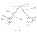
- FIG. 1 shows a first location 1 with a first emitting device 3 and a second emitting device 4. Further shown is a second location 2 with a first receiving device 5 and a second receiving device 6. At the top of the picture, a reflection plane 10 is shown as an example. Furthermore, an exemplary propagation path of the first shaft 11 from the first emitting device 3 to the first receiving device 5 and a propagation path of the second shaft 12 from the second emitting device 4 to the first receiving device 5 are shown by way of example.
- first shaft 11 has an angular divergence 15 with respect to the second shaft 12 when it arrives at the second location 2.
- the Propagation paths for the reception at the second receiving device 6 are not shown here for reasons of clarity.
- the determination of the different directions of incidence takes place in a previously known manner on the basis of the phase differences of the signal components received by an emitting device 3, 4 via a propagation path at the plurality of receiving devices 5, 6.
- the differentiation of the wave components received via different propagation paths takes place on the basis of the decorrelation according to the invention, ie on the basis of different phases, amplitudes and optionally polarizations of the received wave components.
- phase difference results due to different signal propagation path lengths.
- This can be seen in an analogous manner, if one imagines the propagation path of the first shaft 11 and the second shaft 12 from the emitting devices 3, 4 to the second receiving device 6. Then, the signal traveling distance of the first and second shafts 11, 12 to the first receiving device 5 is different from the signal traveling distance to the second receiving device 6. This can be transmitted to two receiving devices 5, 6 for the propagation from one emitting device 3, 4. Then, due to the different lengths of the signal propagation paths of the wave components received at the first receiving device 5 and at the second receiving device 6, a phase difference results.
- the differences that are used to distinguish between individual propagation paths arise due to different signal propagation path lengths and changes in the phase or amplitude and optionally polarization in reflections. This can be seen by considering further propagation paths of the first shaft 11 and the second shaft 12 from the radiating devices 3, 4 to one of the receiving devices 5, 6, such as the direct propagation path. Then, the signal traveling path of the first and second shafts 11, 12 to one of the receiving means 5, 6 is via a first propagation path as compared to the signal propagation path via a second propagation path of different length.
- the Parts of the first shaft 11 and the second shaft 12 received at one of the receiving device 5, 6 via the first propagation path, with respect to the phase position differences to the proportions of the first shaft 11 and the second shaft 12, at one of the receiving device 5, 6 are received via the second propagation path.
- the wave components transmitted via different propagation paths will be reflected at different levels (shown only one level 10) and simply, multiply or not at all, resulting in different changes in the waves in amplitude, phase and / or polarization can.
- the different propagation paths can be distinguished from one another.
- the first shaft 11 radiated from the first radiating device 3 can be distinguished from the second shaft 12 radiated by the second radiating device 4 by various measures. For example, a distinction may be made on the basis of time or chronological sequence or frequency.
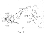
- FIG. 2 shows one of the arrangement FIG. 1 very similar arrangement.
- a first location 1 with a first emitting device 3 and a second emitting device can be seen 4.
- the distance between the first and second emitting device 8 and the distance between the emitting devices and the receiving devices 9, the ratio has effects on the angular divergence 15 of the received wave components.
- a reflection plane 10 is drawn in.
- the propagation of the first shaft 11 and the second shaft 12 are illustrated by different representations of the shaft.
- first and second waves 11, 12 are initially drawn by concentric circles of the same field strength.
- the first wave is illustrated by a line of propagation direction to the reflection plane 10.
- concentric semicircles are then again equal Field strength of a reflected wave component shown.
- the reflected wave is only clarified in the proportion that is reflected at a single point, which is characterized by the solid line of the propagation direction.
- the directions of incidence of the first and second shafts 13, 14 have an angular divergence 15.
- the first and second wave 11, 12 can be distinguished from each other when receiving the decorrelation by the distance 8 between the first and second emitting device 3, 4 .
- the wave components of the first shaft 11 and the second shaft 12, which are reflected at different points, can be assigned to the different propagation paths when the angular divergence 15 of the wave components of the first and second shaft 11, 12 received via a propagation path does not exceed a predetermined extent only the propagation via a propagation path). It is not important here that the directions of incidence of the components of the first shaft 13 and of the second shaft 14, which were received via a propagation path, are distinguished.
- the direction of incidence of the portions of the first and second shaft 11, 12, which were received via a propagation path together, so for example to determine on average.
- the fact that it is not important to determine the direction of incidence of the first and the second wave as separate angle data is also clear from the fact that the angular divergence 15 of the wave components transmitted via a propagation path should preferably not exceed a low upper limit.
Landscapes
- Physics & Mathematics (AREA)
- Engineering & Computer Science (AREA)
- General Physics & Mathematics (AREA)
- Radar, Positioning & Navigation (AREA)
- Remote Sensing (AREA)
- Radar Systems Or Details Thereof (AREA)
Claims (15)
- Procédé d'analyse de trajets de propagation de portions d'ondes comprenant :A le rayonnement d'une première onde à partir d'un premier dispositif de rayonnement en un premier pointB la réception en un second point avec au moins deux dispositifs de réception, des portions d'onde émises de la première ondeC le rayonnement d'une seconde onde à partir d'un second dispositif de rayonnement en un premier pointD la réception au second point des portions d'onde de la seconde onde émiseF l'interprétation des signaux reçus, où les portions d'onde reçues sont séparées selon différentes directions d'incidence des portions d'onde et/ou la détermination de directions d'incidence différentes à partir desquelles les portions d'onde reçues ont été transmises ;où la distance entre le premier dispositif de rayonnement et le second dispositif de rayonnement est inférieure à la distance entre les dispositifs de rayonnement et les dispositifs de réception et caractérisé en ce que les dispositifs de rayonnement sont espacés l'un de l'autre par une distance supérieure à l'erreur associée à la longueur d'onde lorsque l'on analyse les différences de phase de la plus petite longueur d'onde utilisée pour l'analyse de la première onde et de la seconde onde et/ou les dispositifs de rayonnement présentent une caractéristique de rayonnement différente en termes de polarisation.
où ladite opération englobe l'analyse des différences de phase et/ou les amplitudes des signaux desdits au moins deux dispositifs de réception, - Procédé selon la revendication 1, caractérisé en ce que les portions d'onde de la première onde et de la seconde onde ayant sensiblement le même trajet de signal présentent au second point une divergence angulaire inférieure à 10°, en particulier inférieure à 5°, entre les portions d'onde de la première onde et de la seconde onde, où le trajet de signal des portions d'onde considérées n'a aucune réflexion ou seulement des réflexions sur des surfaces planes.
- Procédé selon l'une des revendications précédentes, caractérisé en ce que les phases A et D se déroulent plusieurs fois, en particulier en présence de plus de deux dispositifs de rayonnement.
- Procédé selon l'une des revendications précédentes, caractérisé en ce que l'on utilise des dispositifs de rayonnement identiques comme premier dispositif de rayonnement et comme second dispositif de rayonnement et qu'ils sont espacés l'un de l'autre par une distance supérieure à l'erreur en termes de longueur d'onde lorsque l'on analyse les différences de phase de la plus petite longueur d'onde utilisée pour la première onde et la seconde onde.
- Procédé selon l'une des revendications 1 à 3, caractérisé en ce que l'on utilise un simple dispositif d'émission comme premier dispositif de rayonnement et comme second dispositif de rayonnement, que l'on déplace entre l'exécution de la phase A et l'exécution de la phase C d'une première position au niveau du premier point vers une seconde position au niveau du premier point, où la distance entre la première position et la seconde position est supérieure à l'erreur en termes de longueur d'onde lorsque l'on analyse les différences de phase de la plus petite longueur d'onde de la première onde et de la seconde onde et/ou que l'on déplace le dispositif d'émission de telle sorte qu'il présente une caractéristique de rayonnement différente en termes de polarisation lorsque l'on exécute les phases A et C.
- Procédé selon l'une des revendications précédentes, caractérisé en ce qu'un signal est acheminé aux dispositifs de rayonnement pour émettre des signaux de façon temporaire l'un après l'autre et en particulier avec un décalage de phase différent.
- Procédé selon la revendication ci-dessus, caractérisé en ce que le signal ait des sections temporairement répétées.
- Procédé selon l'une des revendications précédentes, caractérisé en ce que l'interprétation est réalisée sur la base de l'amplitude des portions d'onde reçues.
- Procédé selon la revendication ci-dessus, caractérisé en ce qu'au moins deux dispositifs de rayonnement différents sont employés en termes de caractéristique de rayonnement spatial.
- Procédé selon l'une des revendications précédentes, caractérisé en ce que des ondes soient émises à une fréquence différente à partir d'au moins dispositif de rayonnement et l'interprétation prend en compte les fréquences de portions d'onde reçues.
- Procédé selon l'une des revendications précédentes, caractérisé en ce que la matrice d'antennes sert de dispositifs de réception et/ou de dispositifs de rayonnement.
- Procédé selon l'une des revendications précédentes, caractérisé en ce que les phases A et C, en particulier leur répétition, sont activées par un signal, en particulier des ondes électromagnétiques, en particulier pendant une période prédéterminée.
- Procédé selon l'une des revendications précédentes, caractérisé en ce que l'énergie servant au rayonnement est récupérée, au moins partiellement, de l'énergie acheminée à l'extérieur, en particulier par rayonnement électromagnétique.
- Système comprenant un premier objet avec au moins deux dispositifs de rayonnement et un dispositif de génération de signaux qui peuvent être connectés auxdits dispositifs de rayonnement et un second objet avec au moins deux dispositifs de réception et un dispositif d'interprétation connecté au second objet à travers des moyens de communication, qui divise les portions d'onde reçues par analyse des différences de phase et/ou les amplitudes des signaux des dispositifs de réception selon différentes directions d'incidence des portions d'onde et/ou détermine un certain nombre de directions d'incidence différentes à partir desquelles les portions d'onde reçues ont été transmises,
où la distance entre le premier dispositif de rayonnement et le second dispositif de rayonnement est inférieure à la distance entre les dispositifs de rayonnement et les dispositifs de réception et
caractérisé en ce que le premier dispositif de rayonnement est espacé du second dispositif de rayonnement par une distance qui est supérieure à l'erreur en termes de longueur d'onde lorsque l'on analyse les différences de phase de la plus petite longueur d'onde utilisée pour l'analyse de la première onde et de la seconde onde et/ou les dispositifs de rayonnement présentent une caractéristique de rayonnement différente en termes de polarisation. - Utilisation d'au moins deux dispositifs de rayonnement en un point fixe et au moins deux dispositifs de réception en un second point pour analyser des directions d'incidence, à partir desquelles les portions d'onde émises par les dispositifs de rayonnement ont été transmises au second point, et/ou détermination d'un certain nombre de différentes directions d'incidence, à partir desquelles les portions d'onde émises par les dispositifs de rayonnement ont été transmises au second point, où la distance entre les dispositifs de rayonnement est inférieure à la distance entre les dispositifs de rayonnement et les dispositifs de réception et où les portions d'onde reçues sont analysées et/ou déterminées par analyse des différences de phase,
caractérisée en ce que les dispositifs de rayonnement sont espacés l'un de l'autre par un distance qui est supérieure à l'erreur en termes de longueur d'onde lorsque l'on analyse les différences de phase de la plus petite longueur d'onde utilisée pour l'analyse des différences de phase et/ou les dispositifs de rayonnement présentent une caractéristique de rayonnement différente en termes de polarisation.
Priority Applications (1)
| Application Number | Priority Date | Filing Date | Title |
|---|---|---|---|
| EP09161975.9A EP2259083B1 (fr) | 2009-06-04 | 2009-06-04 | Système décorrélé |
Applications Claiming Priority (1)
| Application Number | Priority Date | Filing Date | Title |
|---|---|---|---|
| EP09161975.9A EP2259083B1 (fr) | 2009-06-04 | 2009-06-04 | Système décorrélé |
Publications (2)
| Publication Number | Publication Date |
|---|---|
| EP2259083A1 EP2259083A1 (fr) | 2010-12-08 |
| EP2259083B1 true EP2259083B1 (fr) | 2015-08-26 |
Family
ID=41531502
Family Applications (1)
| Application Number | Title | Priority Date | Filing Date |
|---|---|---|---|
| EP09161975.9A Active EP2259083B1 (fr) | 2009-06-04 | 2009-06-04 | Système décorrélé |
Country Status (1)
| Country | Link |
|---|---|
| EP (1) | EP2259083B1 (fr) |
Families Citing this family (1)
| Publication number | Priority date | Publication date | Assignee | Title |
|---|---|---|---|---|
| WO2012155990A1 (fr) | 2011-05-18 | 2012-11-22 | Lambda:4 Entwicklungen Gmbh | Procédé permettant de déterminer l'emplacement d'un récepteur |
Family Cites Families (5)
| Publication number | Priority date | Publication date | Assignee | Title |
|---|---|---|---|---|
| AU2002218060A1 (en) * | 2001-12-05 | 2003-06-17 | Austria Wirtschaftsservice Gesellschaft Mit Beschrankter | Method for investigating the propagation of electromagnetic or acoustic waves |
| US7170412B2 (en) * | 2004-08-31 | 2007-01-30 | Symbol Technologies, Inc. | Angle of position object location system and method |
| US8588710B2 (en) * | 2005-10-05 | 2013-11-19 | Telecom Italia S.P.A. | Method and system for multiple antenna communications, related apparatus and corresponding computer program product |
| US8335272B2 (en) * | 2005-10-28 | 2012-12-18 | Koninklijke Philips Electronics N.V. | Multiple antenna transmission with variable diversity gain |
| DE102006004023A1 (de) | 2006-01-27 | 2007-08-09 | Siemens Ag | Vorrichtung und Verfahren zur mehrdimensionalen Ortung von Zielobjekten, insbesondere RFID-Transpondern |
-
2009
- 2009-06-04 EP EP09161975.9A patent/EP2259083B1/fr active Active
Also Published As
| Publication number | Publication date |
|---|---|
| EP2259083A1 (fr) | 2010-12-08 |
Similar Documents
| Publication | Publication Date | Title |
|---|---|---|
| EP1966630B1 (fr) | Dispositif radar à ouverture synthetique haute résolution, et antenne pour un tel dispositif radar | |
| EP2018577B1 (fr) | Système radar haute résolution à visée latérale et à ouverture synthétique utilisant une mise en forme de faisceau numérique | |
| DE19648203C2 (de) | Mehrstrahliges Kraftfahrzeug-Radarsystem | |
| EP0805990B1 (fr) | Systeme radar, notamment pour vehicules a moteur | |
| DE102008059424B4 (de) | Sekundärradarsystem mit dynamischer Sektorisierung des zu überwachenden Raumes unter Verwendung von Multi-Antennenanordnungen und Verfahren hierzu | |
| DE19714570B4 (de) | Mehrstrahliges Radarsystem | |
| EP1628140B1 (fr) | Antenne de réception mono-impulsion interférometrique avec suppression du lobe latéral améliorée | |
| DE2911313A1 (de) | Flughafen-ueberwachungssystem | |
| WO2014139992A4 (fr) | Radar polarimétrique pour la classification d'objets, ainsi que procédé adapté et application adaptée associés | |
| WO2013045232A1 (fr) | Dispositif à radar et procédé pour produire une caractéristique de groupe d'un radar | |
| DE102008010772A1 (de) | Radargerät mit synthetischer Apertur und Verfahren zum Betrieb eines Radargeräts mit synthetischer Apertur | |
| WO2011098173A1 (fr) | Détecteur radar | |
| DE102017223471A1 (de) | Vorrichtung zum Aussenden und Empfangen elektromagnetischer Strahlung | |
| DE102018118863A1 (de) | Radarvorrichtung und Verfahren zum Erzeugen unterschiedlicher Richtcharakteristika | |
| DE102021207330A1 (de) | Koordinierte miniradarzielsimulatoren für verbesserte genauigkeit und verbesserte geistersignalunterbindung | |
| EP2005209B1 (fr) | Procédé et dispositif de saisie d'un ou de plusieurs objets dans l'environnement d'un véhicule à moteur | |
| EP3701280A2 (fr) | Capteur radar comportant une pluralité de directions de rayonnement principales | |
| DE2936168C2 (fr) | ||
| DE102012220773A1 (de) | Vorrichtung und Verfahren zur Elevationswinkelbestimmung in einem Radarsystem | |
| DE102008011889A1 (de) | Digitale Strahlformung mit frequenzmodulierten Signalen | |
| DE102021100695A1 (de) | Verfahren zum Betrieb eines Topologie-erfassenden Radarsystems innerhalb eines Behälters | |
| EP2259083B1 (fr) | Système décorrélé | |
| DE102005037583A1 (de) | Mikrowellen-RFID-System mit adaptiver Strahlformung | |
| EP2722686B1 (fr) | Système sar interférométrique | |
| WO2019242907A1 (fr) | Procédé et dispositif d'évaluation de signaux radar |
Legal Events
| Date | Code | Title | Description |
|---|---|---|---|
| PUAI | Public reference made under article 153(3) epc to a published international application that has entered the european phase |
Free format text: ORIGINAL CODE: 0009012 |
|
| 17P | Request for examination filed |
Effective date: 20100330 |
|
| AK | Designated contracting states |
Kind code of ref document: A1 Designated state(s): AT BE BG CH CY CZ DE DK EE ES FI FR GB GR HR HU IE IS IT LI LT LU LV MC MK MT NL NO PL PT RO SE SI SK TR |
|
| AX | Request for extension of the european patent |
Extension state: AL BA RS |
|
| RIC1 | Information provided on ipc code assigned before grant |
Ipc: G01S 3/74 20060101AFI20110630BHEP Ipc: H04B 7/04 20060101ALI20110630BHEP Ipc: G01S 3/46 20060101ALI20110630BHEP |
|
| GRAP | Despatch of communication of intention to grant a patent |
Free format text: ORIGINAL CODE: EPIDOSNIGR1 |
|
| RIC1 | Information provided on ipc code assigned before grant |
Ipc: G01S 3/46 20060101ALI20150402BHEP Ipc: G01S 3/74 20060101AFI20150402BHEP |
|
| INTG | Intention to grant announced |
Effective date: 20150504 |
|
| GRAS | Grant fee paid |
Free format text: ORIGINAL CODE: EPIDOSNIGR3 |
|
| GRAA | (expected) grant |
Free format text: ORIGINAL CODE: 0009210 |
|
| AK | Designated contracting states |
Kind code of ref document: B1 Designated state(s): AT BE BG CH CY CZ DE DK EE ES FI FR GB GR HR HU IE IS IT LI LT LU LV MC MK MT NL NO PL PT RO SE SI SK TR |
|
| REG | Reference to a national code |
Ref country code: GB Ref legal event code: FG4D Free format text: NOT ENGLISH |
|
| REG | Reference to a national code |
Ref country code: CH Ref legal event code: EP |
|
| REG | Reference to a national code |
Ref country code: AT Ref legal event code: REF Ref document number: 745504 Country of ref document: AT Kind code of ref document: T Effective date: 20150915 |
|
| REG | Reference to a national code |
Ref country code: IE Ref legal event code: FG4D Free format text: LANGUAGE OF EP DOCUMENT: GERMAN |
|
| REG | Reference to a national code |
Ref country code: DE Ref legal event code: R096 Ref document number: 502009011460 Country of ref document: DE |
|
| REG | Reference to a national code |
Ref country code: LT Ref legal event code: MG4D |
|
| PG25 | Lapsed in a contracting state [announced via postgrant information from national office to epo] |
Ref country code: LT Free format text: LAPSE BECAUSE OF FAILURE TO SUBMIT A TRANSLATION OF THE DESCRIPTION OR TO PAY THE FEE WITHIN THE PRESCRIBED TIME-LIMIT Effective date: 20150826 Ref country code: GR Free format text: LAPSE BECAUSE OF FAILURE TO SUBMIT A TRANSLATION OF THE DESCRIPTION OR TO PAY THE FEE WITHIN THE PRESCRIBED TIME-LIMIT Effective date: 20151127 Ref country code: FI Free format text: LAPSE BECAUSE OF FAILURE TO SUBMIT A TRANSLATION OF THE DESCRIPTION OR TO PAY THE FEE WITHIN THE PRESCRIBED TIME-LIMIT Effective date: 20150826 Ref country code: NO Free format text: LAPSE BECAUSE OF FAILURE TO SUBMIT A TRANSLATION OF THE DESCRIPTION OR TO PAY THE FEE WITHIN THE PRESCRIBED TIME-LIMIT Effective date: 20151126 Ref country code: LV Free format text: LAPSE BECAUSE OF FAILURE TO SUBMIT A TRANSLATION OF THE DESCRIPTION OR TO PAY THE FEE WITHIN THE PRESCRIBED TIME-LIMIT Effective date: 20150826 |
|
| REG | Reference to a national code |
Ref country code: NL Ref legal event code: MP Effective date: 20150826 |
|
| PG25 | Lapsed in a contracting state [announced via postgrant information from national office to epo] |
Ref country code: HR Free format text: LAPSE BECAUSE OF FAILURE TO SUBMIT A TRANSLATION OF THE DESCRIPTION OR TO PAY THE FEE WITHIN THE PRESCRIBED TIME-LIMIT Effective date: 20150826 Ref country code: PL Free format text: LAPSE BECAUSE OF FAILURE TO SUBMIT A TRANSLATION OF THE DESCRIPTION OR TO PAY THE FEE WITHIN THE PRESCRIBED TIME-LIMIT Effective date: 20150826 Ref country code: SE Free format text: LAPSE BECAUSE OF FAILURE TO SUBMIT A TRANSLATION OF THE DESCRIPTION OR TO PAY THE FEE WITHIN THE PRESCRIBED TIME-LIMIT Effective date: 20150826 Ref country code: IS Free format text: LAPSE BECAUSE OF FAILURE TO SUBMIT A TRANSLATION OF THE DESCRIPTION OR TO PAY THE FEE WITHIN THE PRESCRIBED TIME-LIMIT Effective date: 20151226 Ref country code: ES Free format text: LAPSE BECAUSE OF FAILURE TO SUBMIT A TRANSLATION OF THE DESCRIPTION OR TO PAY THE FEE WITHIN THE PRESCRIBED TIME-LIMIT Effective date: 20150826 Ref country code: PT Free format text: LAPSE BECAUSE OF FAILURE TO SUBMIT A TRANSLATION OF THE DESCRIPTION OR TO PAY THE FEE WITHIN THE PRESCRIBED TIME-LIMIT Effective date: 20151228 |
|
| PG25 | Lapsed in a contracting state [announced via postgrant information from national office to epo] |
Ref country code: NL Free format text: LAPSE BECAUSE OF FAILURE TO SUBMIT A TRANSLATION OF THE DESCRIPTION OR TO PAY THE FEE WITHIN THE PRESCRIBED TIME-LIMIT Effective date: 20150826 |
|
| PG25 | Lapsed in a contracting state [announced via postgrant information from national office to epo] |
Ref country code: DK Free format text: LAPSE BECAUSE OF FAILURE TO SUBMIT A TRANSLATION OF THE DESCRIPTION OR TO PAY THE FEE WITHIN THE PRESCRIBED TIME-LIMIT Effective date: 20150826 Ref country code: SK Free format text: LAPSE BECAUSE OF FAILURE TO SUBMIT A TRANSLATION OF THE DESCRIPTION OR TO PAY THE FEE WITHIN THE PRESCRIBED TIME-LIMIT Effective date: 20150826 Ref country code: EE Free format text: LAPSE BECAUSE OF FAILURE TO SUBMIT A TRANSLATION OF THE DESCRIPTION OR TO PAY THE FEE WITHIN THE PRESCRIBED TIME-LIMIT Effective date: 20150826 Ref country code: CZ Free format text: LAPSE BECAUSE OF FAILURE TO SUBMIT A TRANSLATION OF THE DESCRIPTION OR TO PAY THE FEE WITHIN THE PRESCRIBED TIME-LIMIT Effective date: 20150826 Ref country code: IT Free format text: LAPSE BECAUSE OF FAILURE TO SUBMIT A TRANSLATION OF THE DESCRIPTION OR TO PAY THE FEE WITHIN THE PRESCRIBED TIME-LIMIT Effective date: 20150826 |
|
| REG | Reference to a national code |
Ref country code: DE Ref legal event code: R097 Ref document number: 502009011460 Country of ref document: DE |
|
| PG25 | Lapsed in a contracting state [announced via postgrant information from national office to epo] |
Ref country code: RO Free format text: LAPSE BECAUSE OF FAILURE TO SUBMIT A TRANSLATION OF THE DESCRIPTION OR TO PAY THE FEE WITHIN THE PRESCRIBED TIME-LIMIT Effective date: 20150826 |
|
| REG | Reference to a national code |
Ref country code: FR Ref legal event code: PLFP Year of fee payment: 8 |
|
| PLBE | No opposition filed within time limit |
Free format text: ORIGINAL CODE: 0009261 |
|
| STAA | Information on the status of an ep patent application or granted ep patent |
Free format text: STATUS: NO OPPOSITION FILED WITHIN TIME LIMIT |
|
| 26N | No opposition filed |
Effective date: 20160530 |
|
| PG25 | Lapsed in a contracting state [announced via postgrant information from national office to epo] |
Ref country code: SI Free format text: LAPSE BECAUSE OF FAILURE TO SUBMIT A TRANSLATION OF THE DESCRIPTION OR TO PAY THE FEE WITHIN THE PRESCRIBED TIME-LIMIT Effective date: 20150826 |
|
| PG25 | Lapsed in a contracting state [announced via postgrant information from national office to epo] |
Ref country code: BE Free format text: LAPSE BECAUSE OF NON-PAYMENT OF DUE FEES Effective date: 20160630 |
|
| PG25 | Lapsed in a contracting state [announced via postgrant information from national office to epo] |
Ref country code: MC Free format text: LAPSE BECAUSE OF FAILURE TO SUBMIT A TRANSLATION OF THE DESCRIPTION OR TO PAY THE FEE WITHIN THE PRESCRIBED TIME-LIMIT Effective date: 20150826 |
|
| REG | Reference to a national code |
Ref country code: CH Ref legal event code: PL |
|
| REG | Reference to a national code |
Ref country code: IE Ref legal event code: MM4A |
|
| PG25 | Lapsed in a contracting state [announced via postgrant information from national office to epo] |
Ref country code: LI Free format text: LAPSE BECAUSE OF NON-PAYMENT OF DUE FEES Effective date: 20160630 Ref country code: CH Free format text: LAPSE BECAUSE OF NON-PAYMENT OF DUE FEES Effective date: 20160630 |
|
| PG25 | Lapsed in a contracting state [announced via postgrant information from national office to epo] |
Ref country code: IE Free format text: LAPSE BECAUSE OF NON-PAYMENT OF DUE FEES Effective date: 20160604 |
|
| REG | Reference to a national code |
Ref country code: FR Ref legal event code: PLFP Year of fee payment: 9 |
|
| REG | Reference to a national code |
Ref country code: AT Ref legal event code: MM01 Ref document number: 745504 Country of ref document: AT Kind code of ref document: T Effective date: 20160604 |
|
| PG25 | Lapsed in a contracting state [announced via postgrant information from national office to epo] |
Ref country code: AT Free format text: LAPSE BECAUSE OF NON-PAYMENT OF DUE FEES Effective date: 20160604 |
|
| PG25 | Lapsed in a contracting state [announced via postgrant information from national office to epo] |
Ref country code: CY Free format text: LAPSE BECAUSE OF FAILURE TO SUBMIT A TRANSLATION OF THE DESCRIPTION OR TO PAY THE FEE WITHIN THE PRESCRIBED TIME-LIMIT Effective date: 20150826 Ref country code: HU Free format text: LAPSE BECAUSE OF FAILURE TO SUBMIT A TRANSLATION OF THE DESCRIPTION OR TO PAY THE FEE WITHIN THE PRESCRIBED TIME-LIMIT; INVALID AB INITIO Effective date: 20090604 |
|
| REG | Reference to a national code |
Ref country code: FR Ref legal event code: PLFP Year of fee payment: 10 |
|
| PG25 | Lapsed in a contracting state [announced via postgrant information from national office to epo] |
Ref country code: MK Free format text: LAPSE BECAUSE OF FAILURE TO SUBMIT A TRANSLATION OF THE DESCRIPTION OR TO PAY THE FEE WITHIN THE PRESCRIBED TIME-LIMIT Effective date: 20150826 Ref country code: MT Free format text: LAPSE BECAUSE OF FAILURE TO SUBMIT A TRANSLATION OF THE DESCRIPTION OR TO PAY THE FEE WITHIN THE PRESCRIBED TIME-LIMIT Effective date: 20150826 Ref country code: LU Free format text: LAPSE BECAUSE OF NON-PAYMENT OF DUE FEES Effective date: 20160604 Ref country code: TR Free format text: LAPSE BECAUSE OF FAILURE TO SUBMIT A TRANSLATION OF THE DESCRIPTION OR TO PAY THE FEE WITHIN THE PRESCRIBED TIME-LIMIT Effective date: 20150826 |
|
| PG25 | Lapsed in a contracting state [announced via postgrant information from national office to epo] |
Ref country code: BG Free format text: LAPSE BECAUSE OF FAILURE TO SUBMIT A TRANSLATION OF THE DESCRIPTION OR TO PAY THE FEE WITHIN THE PRESCRIBED TIME-LIMIT Effective date: 20150826 |
|
| PGFP | Annual fee paid to national office [announced via postgrant information from national office to epo] |
Ref country code: FR Payment date: 20230622 Year of fee payment: 15 Ref country code: DE Payment date: 20230525 Year of fee payment: 15 |
|
| PGFP | Annual fee paid to national office [announced via postgrant information from national office to epo] |
Ref country code: GB Payment date: 20230622 Year of fee payment: 15 |