EP2258577A1 - Shift operation device - Google Patents
Shift operation device Download PDFInfo
- Publication number
- EP2258577A1 EP2258577A1 EP09723885A EP09723885A EP2258577A1 EP 2258577 A1 EP2258577 A1 EP 2258577A1 EP 09723885 A EP09723885 A EP 09723885A EP 09723885 A EP09723885 A EP 09723885A EP 2258577 A1 EP2258577 A1 EP 2258577A1
- Authority
- EP
- European Patent Office
- Prior art keywords
- core
- lever shaft
- operation device
- shift operation
- axial direction
- Prior art date
- Legal status (The legal status is an assumption and is not a legal conclusion. Google has not performed a legal analysis and makes no representation as to the accuracy of the status listed.)
- Granted
Links
Images



Classifications
-
- G—PHYSICS
- G05—CONTROLLING; REGULATING
- G05G—CONTROL DEVICES OR SYSTEMS INSOFAR AS CHARACTERISED BY MECHANICAL FEATURES ONLY
- G05G1/00—Controlling members, e.g. knobs or handles; Assemblies or arrangements thereof; Indicating position of controlling members
- G05G1/04—Controlling members for hand actuation by pivoting movement, e.g. levers
- G05G1/06—Details of their grip parts
-
- F—MECHANICAL ENGINEERING; LIGHTING; HEATING; WEAPONS; BLASTING
- F16—ENGINEERING ELEMENTS AND UNITS; GENERAL MEASURES FOR PRODUCING AND MAINTAINING EFFECTIVE FUNCTIONING OF MACHINES OR INSTALLATIONS; THERMAL INSULATION IN GENERAL
- F16H—GEARING
- F16H59/00—Control inputs to control units of change-speed- or reversing-gearings for conveying rotary motion
- F16H59/02—Selector apparatus
- F16H59/0278—Constructional features of the selector lever, e.g. grip parts, mounting or manufacturing
-
- F—MECHANICAL ENGINEERING; LIGHTING; HEATING; WEAPONS; BLASTING
- F16—ENGINEERING ELEMENTS AND UNITS; GENERAL MEASURES FOR PRODUCING AND MAINTAINING EFFECTIVE FUNCTIONING OF MACHINES OR INSTALLATIONS; THERMAL INSULATION IN GENERAL
- F16H—GEARING
- F16H59/00—Control inputs to control units of change-speed- or reversing-gearings for conveying rotary motion
- F16H59/02—Selector apparatus
- F16H2059/0291—Selector apparatus comprising safety means for preventing injuries in case of accidents
-
- Y—GENERAL TAGGING OF NEW TECHNOLOGICAL DEVELOPMENTS; GENERAL TAGGING OF CROSS-SECTIONAL TECHNOLOGIES SPANNING OVER SEVERAL SECTIONS OF THE IPC; TECHNICAL SUBJECTS COVERED BY FORMER USPC CROSS-REFERENCE ART COLLECTIONS [XRACs] AND DIGESTS
- Y10—TECHNICAL SUBJECTS COVERED BY FORMER USPC
- Y10T—TECHNICAL SUBJECTS COVERED BY FORMER US CLASSIFICATION
- Y10T74/00—Machine element or mechanism
- Y10T74/20—Control lever and linkage systems
- Y10T74/20012—Multiple controlled elements
- Y10T74/20018—Transmission control
- Y10T74/2014—Manually operated selector [e.g., remotely controlled device, lever, push button, rotary dial, etc.]
-
- Y—GENERAL TAGGING OF NEW TECHNOLOGICAL DEVELOPMENTS; GENERAL TAGGING OF CROSS-SECTIONAL TECHNOLOGIES SPANNING OVER SEVERAL SECTIONS OF THE IPC; TECHNICAL SUBJECTS COVERED BY FORMER USPC CROSS-REFERENCE ART COLLECTIONS [XRACs] AND DIGESTS
- Y10—TECHNICAL SUBJECTS COVERED BY FORMER USPC
- Y10T—TECHNICAL SUBJECTS COVERED BY FORMER US CLASSIFICATION
- Y10T74/00—Machine element or mechanism
- Y10T74/20—Control lever and linkage systems
- Y10T74/20576—Elements
- Y10T74/20582—Levers
-
- Y—GENERAL TAGGING OF NEW TECHNOLOGICAL DEVELOPMENTS; GENERAL TAGGING OF CROSS-SECTIONAL TECHNOLOGIES SPANNING OVER SEVERAL SECTIONS OF THE IPC; TECHNICAL SUBJECTS COVERED BY FORMER USPC CROSS-REFERENCE ART COLLECTIONS [XRACs] AND DIGESTS
- Y10—TECHNICAL SUBJECTS COVERED BY FORMER USPC
- Y10T—TECHNICAL SUBJECTS COVERED BY FORMER US CLASSIFICATION
- Y10T74/00—Machine element or mechanism
- Y10T74/20—Control lever and linkage systems
- Y10T74/20576—Elements
- Y10T74/20582—Levers
- Y10T74/20612—Hand
Definitions
- the present invention relates to a shift operation device having a lever knob which can absorb an impact load that is applied on the lever knob.
- Patent Literature 1 a technology for absorbing an impact load is disclosed in a Patent Literature 1, where in order to absorb the impact load input to a shift operation device (operation lever) which is arranged in an instrument panel or its vicinity, a slit is disposed in a bracket supporting the whole shift operation device to support thereof with a support member, and, for example, if the impact load is applied on the shift operation device, the shift operation device slides along the slit, while breaking the support member, to absorb the impact load.
- a shift operation device operation lever
- a slit is disposed in a bracket supporting the whole shift operation device to support thereof with a support member, and, for example, if the impact load is applied on the shift operation device, the shift operation device slides along the slit, while breaking the support member, to absorb the impact load.
- an object of the present invention to provide a shift operation device provided with a lever knob which can absorb an impact load operating in the axial direction of a lever shaft with a simple structure.
- a shift operation device which includes a lever shaft supported by a vehicle, a lever knob provided in an upper end portion of the lever shaft, a core provided inside the lever knob and fixed to the upper end portion of the lever shaft, a connection member for fixing the core to the lever shaft, and a hollow portion which is provided on an upper side of the lever shaft than the connection member and inside the core.
- An outer periphery portion of the core is formed to be thin by disposing the hollow portion.
- a first weak portion to which a load caused by a deformation of the outer periphery portion is applied is formed between the hollow portion and the connection member of the core. The outer periphery portion is deformed by a load operating in an axial direction of the lever shaft.
- an impact load can be absorbed through breaking of the weak portion utilizing the hollow portion by disposing the first weak portion, which is weak against a load operating in the axial direction of the lever shaft, in the core of the lever knob provided in the upper end portion of the lever shaft.
- the shift operation device in which the connection member comprises a screw, and the core comprises a cylindrical boss into which the screw is inserted in a direction perpendicular to the axial direction of the lever shaft and a sidewall standing in a height direction of the cylindrical boss and forming the hollow portion.
- the cylindrical boss and the sidewall are formed in line in the axial direction of the lever shaft and a cylindrical portion of the cylindrical boss and the sidewall are connected by a stiffening rib, and the first weak portion is disposed in a connection portion between the cylindrical portion and the stiffening rib.
- the cylindrical boss into which the screw of the connection member is inserted and the sidewall forming the hollow portion are formed in line in the axial direction of the lever shaft and connected by the stiffening rib, and the first weak portion is disposed in the connection portion between the stiffening rib and the cylindrical boss.
- the shift operation device in which the core is provided with a second weak portion which is weak against a load operating in the axial direction of the lever shaft in the outer periphery portion of the core forming a surrounding of the hollow portion.
- the second weak portion which is weak against a load operating in the axial direction of the lever shaft is disposed by forming a thin portion in the outer periphery portion of the core forming a surrounding of the hollow portion, and thereby an impact load can be absorbed through breaking of the second weak portion.
- the shift operation device in which the core is provided with the second weak portion by forming a concave groove in the outer periphery portion on each of right and left sides of the hollow portion.
- the core is provided with the second weak portion by forming the concave groove in the outer periphery portion on each of right and left sides of the hollow portion. Due to this structure, the core easily expands to right and left to be broken, and the first weak portion can be formed to easily expand to right and left to be broken, accordingly.
- the shift operation device in which the core is provided with the second weak portion by forming a concave groove along a standing direction of the sidewall in the outer periphery portion on each of the right and left sides of the hollow portion.
- the core is provided with the second weak portion by forming the concave groove along the standing direction of the sidewall in the outer periphery portion on each of the right and left sides of the hollow portion. Due to this structure, the core easily expands to right and left to be broken, and accordingly, the first weak portion can be formed to easily expand to right and left to be broken.
- the shift operation device in which a thin portion which is weak against a load operating in the axial direction of the lever shaft is disposed in a connection portion between the sidewall and the outer periphery portion.
- the thin portion can be formed in the connection portion between the sidewall and the outer periphery portion of the core.
- the thin portion forms a weak portion which is weak against a load operating in the axial direction of the lever shaft, and can form an origin of breaking of the core.
- the shift operation device in which a space portion which is weak against a load operating in the axial direction of the lever shaft is disposed by emptying a part of the outer periphery portion.
- the space portion can be formed by emptying a part of the outer periphery portion.
- the space portion is weak against a load operating in the axial direction of the lever shaft, and can form an origin of breaking of the core.
- the shift operation device in which a groove portion which is weak against a load operating in the axial direction of the lever shaft is disposed on an outer wall surface of the outer periphery portion.
- the groove portion can be formed on the outer wall surface of the outer periphery portion.
- the groove portion forms a weak portion which is weak against a load operating in the axial direction of the lever shaft by forming the outer periphery portion to be thin, and can form an origin of breaking of the core.
- the core can be easily broken through deformation in the right and left direction due to extension of the hollow portion and the weak portions by forming the core to easily expand to right and left due to the hollow portion. Accordingly, a shift operation device provided with a lever knob which can absorb an impact load operating in the axial direction of the lever shaft can be provided with a simple structure. In addition, a structure such as a shift button may be arranged in the hollow portion.
- FIG. 1A is a perspective view of an outer appearance of a shift operation device
- FIG. 1B is an illustration showing an inner structure of a lever knob.
- a shift operation device 100 of an automatic transmission according to the present embodiment is provided with, for example, a lever knob 1 that a driver grips on an upper end portion of a lever shaft 5.
- the lever knob 1 includes a shift button 2 which releases a shift lock of the shift operation device 100 and an overdrive button 3 which allows switching ON/OFF of an overdrive mode, and an outer cover 4 is fixed on the lever knob 1 so as to cover an inner structure of the lever knob 1.
- the lever knob 1 is formed in such a manner that an outer 10 made of, for example, styrene-based thermoplastic elastomer covers a core 11 made of, for example, polyacetal.
- a hollow portion 11a is formed by a sidewall 11a1 of the core 11 on a side of a vertex portion T of the outer 10 in order to reduce a weight of the lever knob 1 and secure a space for housing the shift button 2.
- the sidewall 11a1 is disposed so as to surround the hollow portion 11a to ensure strength of the lever knob 1.
- an up-and-down direction of the lever knob 1 is set so that a side of the vertex portion T of the outer 10 is the upper side.
- a side on which the shift button 2 is arranged is named as an operation face, and the opposite side thereof is named as a backside.
- FIG. 2A is a cross sectional view of FIG. 1A taken along X-X line.
- an insertion portion 11c having a space portion 11c1 into which a lever main body 15 that is an axial portion of the lever shaft 5 is inserted is formed below the core 11 so as to extend downward from the hollow portion 11a.
- the lever main body 15 is inserted into the insertion portion 11c so that an upper end of the lever main body 15 is located below the hollow portion 11a. That is, the hollow portion 11a is formed on the upper end side of the lever shaft 5.
- the lever main body 15 that is inserted into the insertion portion 11c is fixed to the insertion portion 11c with screws (screw members) 13 which are fitted up in a direction perpendicular to an axial direction of the lever main body 15, that is, the axial direction of the shaft 5.
- screws (screw members) 13 which are fitted up in a direction perpendicular to an axial direction of the lever main body 15, that is, the axial direction of the shaft 5.
- a screw cramp portion 11b is formed in the insertion portion 11c of the core 11.
- the screw cramp portion 11b is formed so that the screw 13 is inserted into a cylindrical boss which is formed in the insertion portion 11c (see FIG. 2A ), and includes a cylindrical portion 11b1 which is formed so as to surround the screw 13 and a through-hole not shown that a screw portion of the screw 13 passes though.
- the screw cramp portion 11b is the cylindrical boss.
- a screw hole not shown with which the screw portion of the screw 13 is screwed together is formed in the lever main body 15, and as shown in FIG. 2A , the core 11 is fixed to the lever main body 15 with the screw 13.
- the lever shaft 5 may be formed in such a manner that a lever main body 15 exposed outside from the outer 10 is covered by a cover member 15a made of, for example, resin as shown in FIG. 2A .
- the insertion portion 11c is formed so as to connect to a lower side of the sidewall 11a1 (see FIG. 2B ) of the hollow portion 11a, and the space portion 11c1 of the insertion portion 11c is formed passing through the side wall 11a1. Namely, the space portion 11c1 of the insertion portion 11c is formed so as to communicate with the hollow portion 11a.
- the lever shaft 5 of the shift operation device 100 is a member connecting between an automatic transmission, not shown, and the lever knob 1, and includes the lever main body 15 having, for example, a pipe shape.
- a rod 14 for releasing a shift lock is provided in the space portion of the lever main body 15 of the lever shaft 5 in such a manner that the rod 14 freely moves through the space portion in the up-and-down direction, and an upper end of the rod 14 is projected into the hollow portion 11a of the core 11.
- the hollow portion 11a of the core 11 is provided with the shift button 2 which moves the rod 14 in the up-and-down direction.
- FIG. 2B is an enlarged view of the hollow portion.
- a hinge portion 2a supporting the shift button 2 is formed standing in the hollow portion 11a ranging from a back side of the exterior portion 11e (see FIG. 3A ) forming an outer appearance of a backside of the core 11 to the up-and-down direction.
- Two hinge portions 2a described above are formed so as to sandwich the shift button 2, and the shift button 2 is swingably supported by the two hinge portions 2a through a rotation shaft 2b.
- two recesses 11a2 are formed in the sidewall 11a1.
- an arm 2c which operates together with the shift button 2 is provided in the shift button 2, and if the shift button 2 swings around the rotation shaft 2b, the arm 2c swings together with the shift button 2 around the rotation shaft 2b.
- the arm 2c is configured in such a manner that if the shift button 2 is pushed toward a back side of the lever knob 1, the arm 2c moves downward.
- the upper end of the rod 14 and the arm 2c are configured to come in contact with each other, and if the shift button 2 rotates in a direction that the shift button 2 is pushed into the core 11, the rod 14 moves downward by the arm 2c. Namely, if the driver operates the shift button 2 to be pushed into the lever knob 1, the rod 14 moves downward.
- the shift operation device 100 (see FIG. 1A ) is configured so that a shift lock is released when the rod 14 moved downward, the shift lock of the shift operation device 100 is released if the driver operates the shift button 2.
- the rod 14 is configured to be pushed upward by a pushing means not shown, the arm 2c is pushed upward by the rod 14, and the shift button 2 is pushed in a direction to project toward the operation face from the lever knob 1.
- an overdrive button 3 is provided in the lever knob 1.
- a push switch 3a which switches ON/OFF of an electric connection may be used for the overdrive button 3.
- the overdrive button 3 may be provided in such a manner that the push switch 3a is fixed to, for example, the core 11 by a fixing means not shown so that the operation portion protrudes from the operation face side of the lever knob 1 and the driver can operate the operation portion.
- a method for mounting the outer cover 4 shown in FIG. 2A is not limited, and for example, by forming an engagement click not shown in the outer cover 4 and an engagement hole not shown in the core 11, the engagement click in the outer cover 4 may be engaged with the engagement hole in the core 11.
- FIG. 1A, FIG. 1B , FIG. 2A, and FIG. 2B exemplify a selector lever of an automatic transmission, as the shift operation device 100 (see FIG. 1A ).
- the overdrive button 3 including the push switch 3a, the shift button 2, the arm 2c, and the rod 14 which are shown in FIG. 2A may be eliminated.
- the hinge portion 2a (see FIG. 2B ) supporting the shift button 2 may be eliminated.
- the recess 11a2 may be formed as a weak portion described later.
- FIG. 3A is a perspective view showing a core of a lever knob according to the embodiment of the present invention
- FIG. 3B is an illustration of an exterior portion as seen from an operation face side
- FIG. 3C is an illustration showing a deformation of the exterior portion.
- the exterior portion 11e which is a box having a bottom and whose operation face side is opened forms an outer appearance of a backside of the core 11, and, for example, the hollow portion 11a, the two screw cramp portions 11b, 11b, and the insertion portion 11c are formed inside the opening of the exterior portion 11e.
- the sidewall 11a1 stands toward the operation face side from the backside to form the hollow portion 11a having substantially a rectangular shape as seen from the operation face side.
- the insertion portion 11c is formed on the lower side of the sidewall 11a1.
- the exterior portion 11e and the sidewall 11a1 form an outer circumferential portion.
- the insertion portion 11c is formed as a ridge protrusion extending in the up-and-down direction.
- the insertion portion 11c is formed so that one end of the ridge protrusion is connected to the lower side of the sidewall 11a1, and a space portion 11c1 into which the lever main body 15 (see FIG. 2A ) is inserted is formed in the ridge protrusion along the protrusion.
- the space portion 11c1 of the insertion portion 11c is formed so as to penetrate the sidewall 11a1, and the hollow portion 11a communicates with the space portion 11c1 of the insertion portion 11c.
- the other end, which is not connected to the sidewall 11a1, of the insertion portion 11c may be projected from the lower side of the exterior portion 11e to form, for example, an engagement portion 11c2 engaging with a cover member 15a (see FIG. 2A ) covering the lever main body 15 (see FIG. 2A ).
- two screw cramp portions 11b each consisting of a cylindrical boss are arranged along the insertion portion 11c so as to open to the operation face side. That is, the sidewall 11a1 and the screw cramp portions 11b, 11b are formed in line along the insertion portion 11c. In other words, the sidewall 11a1 and the screw cramp portions 11b, 11b are formed in line in the axial direction of the lever main body 15 (see FIG. 2A ) to be inserted into the insertion portion 11c, that is, in the axial direction of the lever shaft 5 (see FIG. 2A ).
- the screw cramp portion 11b consists of a cylindrical boss, and includes a cylinder portion 11b1 surrounding a screw 13 shown in FIG. 2A .
- the cylindrical portion 11b1 of the upper screw cramp portion 11b and the cylindrical portion 11b1 of the lower screw cramp portion 11b are connected by a stiffening rib 11d which is formed on a line connecting between substantially centers of respective screw cramp portions.
- the cylindrical portion 11b1 of the lower screw cramp portion 11b is connected to the exterior portion 11e by the stiffening rib 11d.
- an upper portion of the sidewall 11a1 forming the hollow portion 11a is connected to the exterior portion 11e by the stiffening rib 11d.
- the screw cramp portion 11b consists of a cylindrical boss opening to the operation face side, and the sidewall 11a1 stands toward the operation face side from a back side of the exterior portion 11e. Therefore, the sidewall 11a1 is formed to stand in a height direction of the screw cramp portion 11b. Then, the cylindrical portion 11b1 of the upper screw cramp portion 11b is connected to the lower side of the sidewall 11a1 forming the hollow portion 11a by the stiffening rib 11d.
- the cylindrical portion 11b1 of the upper screw portion 11b and the sidewall 11a1 are connected by a single stiffening rib 11d (center rib 11d1) which is formed on a line along the insertion portion 11c through substantially the center of the screw cramp portion 11b and by two stiffening ribs 11d, 11d (side ribs 11d2, 11d2) which are formed toward respective lower corners of the sidewall 11a1 from the cylindrical portion 11b1.
- the center rib 11d1 is formed in the axial direction of the lever main body 15 (see FIG. 2A ), that is, in the axial direction of the lever shaft 5 (see FIG. 2A ).
- the lower side of the sidewall 11a1 forming the hollow portion 11a and the cylindrical portion 11b1 of the upper screw cramp portion 11b are connected by the stiffening rib 11d
- the cylindrical portion 11b1 of the upper screw cramp portion 11b and the cylindrical portion 11b1 of the lower screw cramp portion 11b are connected by the stiffening rib 11b
- the cylindrical portion 11b1 of the lower screw cramp portion 11b and the exterior portion 11e are connected by the stiffening rib 11d.
- the exterior portion 11e and the upper side of the sidewall 11a1 forming the hollow portion 11a are connected by the stiffening rib 11d.
- the structure as described above ensures a strength of the core 11 against a load operating in the axial direction of the lever main bogy 15 (see FIG. 2A ), that is, in the axial direction (hereinafter, referred to as up-and-down direction) of the lever shaft 5 (see FIG. 2A ).
- a V-shaped cut-out groove 110 formed in a height direction of the cylindrical portion 11b1 is disposed in a connection portion between the center rib 11d1 and the cylindrical portion 11b1 of the upper screw cramp portion 11b. The V-shaped cut-out groove 110 will be described later in detail.
- the number of the screw cramp portions 11b is not limited, and may be one, or may be more than two. If the number of the screw cramp portions 11b is more than two, the cylindrical portion 11b1 of each of the screw cramp portions may be connected by the stiffening rib 11d. In addition, the screw cramp portions 11b which is formed to be closest to the sidewall 11a1 of the hollow portion 11a and the lower side of the sidewall 11a1 may be connected by one center rib 11d1 and two side ribs 11d2, 11d2.
- the lever knob 1 (see FIG. 1A ) according to the embodiment of the present invention is provided with a weak portion in the core 11 (see FIG. 1B ), and if a load (for example, impact load) exceeding a predetermined value and operating in the up-and-down direction is applied in the axial direction of the lever shaft 5 (see FIG. 2A ) from the vertex portion T of the lever knob 1, the core 11 is crashed at the weak portion to absorb the load.
- the predetermined value may be set as appropriated based on, for example, vehicle performances required for the vehicle provided with the shift operation device 100 (see FIG. 1A ).
- a V-shaped groove (concave groove) 11e1 is formed at a position, for example, facing the recess 11a2 of the sidewall 11a1 in a groove-like shape toward the back side from the operation face side.
- the V-shaped groove 11e1 is formed along a standing direction of the sidewall 11a1.
- the V-shaped groove 11e1 may be one, or may be more than one.
- the V-shaped groove 11e1 described above is disposed on each side of the hollow portion 11a as seen from the operation face side as shown, for example, in FIG. 3A and FIG. 3B . Meanwhile, a depth of the V-shaped groove 11e1 from the operation face may be set as appropriate based on, for example, the strength required for the core 11.
- a stress occurs in the exterior portion 11e.
- a stress concentration occurs in the formed V-shaped groove 11e1
- deformation and breaking of the exterior portion 11e originate from the V-shaped groove 11e1. Since a portion of the V-shaped groove 11e1 is formed to be thin, as shown in FIG. 3A , a thin portion due to the exterior portion 11e is formed around the hollow portion 11a.
- the V-shaped groove 11e1 causes deformation and breaking of the exterior portion 11e, and accordingly, the V-shaped groove 11e1 forms a weak portion (second weak portion).
- FIG. 4A is a cross sectional view of FIG. 3A taken along Y-Y line
- FIG. 4B is a schematic illustration showing a state in that a core deforms at a thin portion.
- the hollow portion 11a is formed so that an outer periphery portion including the exterior portion 11e of the core 11 becomes to be thin.
- a connection portion between the sidewall 11a1 of the hollow portion 11a and the exterior portion 11e is formed to be further thinner to form a thin portion 11f.
- the standing portion of the sidewall 11a1 of the core 11 is formed to be thin.
- the load P operating in the up-and-down direction is applied to the vertex portion T of the exterior portion 11e, a stress occurs in the exterior portion 11e, and a stress concentration occurs at the connection portion between the sidewall 11a1 and the exterior portion 11e.
- the thin portion 11f is disposed in the connection portion where the stress concentration occurs between the sidewall 11a1 and the exterior portion 11e so that the deformation and breaking of the core 11 originate from the thin portion 11f.
- FIG. 4B if the load P operating in the up-and-down direction is applied to the vertex portion T of the core 11 configured as described above, a stress occurs in the core 11, and stress concentrations occur at the thin portion 11f and at a vertex angle portion of the V-shaped groove 11e1 (see FIG. 3A ) formed in the exterior portion 11e.
- the stress occurred in the core 11 is transferred to the sidewall 11a1, and a stress concentration occurs at the recess 11a2 (see FIG. 3A ). If the stress occurred in the core 11 exceeds the predetermined value, the recess 11a2 of the sidewall 11a1 deforms in the up-and-down direction to be crashed and broken.
- FIG. 4B if the load P operating in the up-and-down direction is applied to the vertex portion T of the core 11 configured as described above, a stress occurs in the core 11, and stress concentrations occur at the thin portion 11f and at a vertex angle portion of the V-shaped groove 11e1 (see FIG. 3A )
- the exterior portion 11e deforms to break at the V-shaped groove 11e1, as well as the thin portion 11f breaks as shown in FIG. 4B .
- the load P which was applied to the core 11, operating in the up-and-down direction is absorbed through the breaking of the core 11.
- the vertex portion T of the core 11 deforms to be depressed into the hollow portion 11a. Therefore, the hollow portion 11a serves to absorb the deformation of the core 11.
- FIG. 5A is a cross sectional view of FIG. 3A taken along Z-Z line, which is a backside of a core as seen from the operation face side
- FIG. 5B is a schematic illustration showing a state in that the core deforms at a weak portion on the back side of the core.
- a plurality of space portions 11g are formed on the back side of the exterior portion 11e of the core 11 by emptying the exterior portion 11e.
- a plurality of groove portions 11h (four in FIG.
- the space portions 11g and the groove portions 11h formed as described above form weak portions in the case that the load P operating in the up-and-down direction is applied to the vertex portion T of the core 11.
- a thin portion is formed in the core 11 by forming the plurality of the groove portions 11h on the outer wall surface 11s of the exterior portion 11e of the core 11. Then, if the load P operating in the up-and-down direction is applied to the vertex portion T, the thin portions due to the groove portions 11h and the space portions 11g deform to form origins of breaking of the core 11 as shown in FIG. 5B .
- a weak portion is also formed in the screw cramp portion 11b (see FIG. 3A ) of the core 11 (see FIG. 3A ).
- FIG. 6 is an enlarged view of an A portion of FIG. 3A .
- V-shaped cut-out grooves 110 which are formed in the height direction of a boss forming the screw cramp portion 11b are formed in the connection portion between the cylindrical portion 11b1 of the upper screw cramp portion 11b and the center rib 11d1.
- the cylindrical portion 11b1 at the connection portion connecting with the center rib 11d1 can be formed thinner than the other portions of the cylindrical portion 11b1.
- a stress operating in the up-and-down direction and exceeding a predetermined value occurs in the center rib 11d1.
- the upper screw cramp portion 11b breaks starting from the cut-out grooves 110 to absorb the load applied to the core 11.
- the V-shaped cut-out grooves 110 also form weak portions (first weak portion) of the core 11.
- a shape of the cut-out grooves 110 is not limited to a V shape, and, for example, a rectangular shape or a semicircular shape may be used. Other than those, the shape is not limited as long as at least one part of the cylindrical portion 11b1 is formed to be thinner than the other parts.
- FIG. 7 is a graph showing a relationship between a load applied on a core and an amount of deformation of the core.
- the load P compressive load
- FIG. 3A the load P operating in the up-and-down direction
- a deformation amount ⁇ 1 of the core 11 increases as the load P increases.
- the screw cramp portion 11b see FIG. 3A
- the screw cramp portion 11b breaks at the cut-out grooves 110 (see FIG. 3A ).
- the hollow portion 11a see FIG.
- a strength of the core 11 is designed in such a manner that when the applied load P to the core 11 (see FIG. 4A ) is increased, the screw cramp portion 11b (see FIG. 3A ) breaks first at the cut-out grooves 110 (see FIG. 3A ), and the applied load p is further increased, the hollow portion 11a (see FIG. 3A ) breaks next at the V-shaped grooves 11e1 (see FIG. 3A ) of the exterior portion 11e and at the thin portions 11f (see FIG. 4A ).
- the core 11 can absorb the initial impact load through breaking of the screw cramp portion 11b, and the secondary impact load following the initial impact load through the breaking of the hollow portion 11a.
- the shift operation device 100 (see FIG. 1A ) according to the embodiment is provided with the weak portions in the core 11 (see FIG. 3A ) forming the lever knob 1 (see FIG. 1A ), and when a load operating in the up-and-down direction and exceeding the predetermined value is applied to the vertex portion of the lever knob 1 as an impact load, the inner structure of the lever knob 1 breaks. Therefore, the initial impact load and the secondary impact load following the initial impact load can be effectively absorbed through the breaking of the lever knob 1, accordingly.
- an outer periphery portion including the exterior portion 11e (see FIG. 3A ) of the core 11 is formed to be thin so as to expand easily to right and left, thereby, a breaking of the core 11 through deformation of the core 11 in the right and left direction can be easily achieved by expansion of the hollow portion 11a and the weak portions. Therefore, the lever knob 1 (see FIG. 1A ) can absorb the impact load operating in the axial direction of the lever shaft 5 (see FIG. 1A ) with a simple structure.
- the core 11 of the lever knob 1 has a structure that easily deforms in the right and left direction to be broken at the hollow portion 11a, the connection portion between the center rib 11d1 (see FIG. 6 ) and the cylindrical portion 11b1 easily breaks to right and left at the cut-out grooves 110 (see FIG. 6 ).
- an impact load operating in the axial direction of the lever shaft 5 can be absorbed through the breaking of the connection portion between the center rib 11d1 and the cylindrical portion 11b1.
- a structure such as a shift button 2 (see FIG. 2B ) may be arranged in the hollow portion 11a.
- the load P 1 with which the screw cramp portion 11b (see FIG. 3A ) breaks at the cut-out grooves 110 (see FIG. 3A ), the load P 2 with which the hollow portion 11a (see FIG. 3A ) breaks at the V-shaped grooves 11e1 (see FIG. 3A ) and at the thin portion 11f (see FIG. 4A ), and the deformation amount ⁇ 1 by the applied load P are not limited specifically, and may be set as appropriate based on vehicle performances required for the vehicle.
- the screw cramp portion 11b breaks first at the cut-out grooves 110 (see FIG. 3A ), and if the applied load P is further increased, the hollow portion 11a (see FIG. 3A ) breaks at the V-shaped grooves 11e1 (see FIG. 3A ) of the exterior portion 11e and at the thin portions 11f (see FIG. 4A ).
- the order of breaking is not limited to this, and the hollow portion 11a (see FIG. 3A ) may break first at the V-shaped grooves 11e1 of the exterior portion 11e and at the thin portions 11f.
Landscapes
- Engineering & Computer Science (AREA)
- General Engineering & Computer Science (AREA)
- Mechanical Engineering (AREA)
- Physics & Mathematics (AREA)
- General Physics & Mathematics (AREA)
- Automation & Control Theory (AREA)
- Arrangement Or Mounting Of Control Devices For Change-Speed Gearing (AREA)
- Vibration Dampers (AREA)
Abstract

Description
- The present invention relates to a shift operation device having a lever knob which can absorb an impact load that is applied on the lever knob.
- To secure an interior space on the floor of a vehicle by arranging a shift operation device of a manual transmission or an automatic transmission in an instrument panel of the vehicle or its vicinity is widely carried out.
- For example, a technology for absorbing an impact load is disclosed in a
Patent Literature 1, where in order to absorb the impact load input to a shift operation device (operation lever) which is arranged in an instrument panel or its vicinity, a slit is disposed in a bracket supporting the whole shift operation device to support thereof with a support member, and, for example, if the impact load is applied on the shift operation device, the shift operation device slides along the slit, while breaking the support member, to absorb the impact load. - Patent Literature 1: Japanese Patent Laid-Open Publication No.
2002-029275 - However, in the technology disclosed in the
Patent Literature 1, a structure that slides the shift operation device along the slit when an impact load is applied is required, thereby resulting in increase in production cost due to increase in the number of components and decrease in production efficiency due to increase in complexity of the structure.
In addition, due to the requirement of the structure that slides the shift operation device along the slit, downsizing of the shift operation device and the bracket is limited. - It is, therefore, an object of the present invention to provide a shift operation device provided with a lever knob which can absorb an impact load operating in the axial direction of a lever shaft with a simple structure.
- In order to solve the forgoing problems, according to a first aspect of the present invention, there is provided a shift operation device which includes a lever shaft supported by a vehicle, a lever knob provided in an upper end portion of the lever shaft, a core provided inside the lever knob and fixed to the upper end portion of the lever shaft, a connection member for fixing the core to the lever shaft, and a hollow portion which is provided on an upper side of the lever shaft than the connection member and inside the core. An outer periphery portion of the core is formed to be thin by disposing the hollow portion. A first weak portion to which a load caused by a deformation of the outer periphery portion is applied is formed between the hollow portion and the connection member of the core. The outer periphery portion is deformed by a load operating in an axial direction of the lever shaft.
- In the first aspect of the present invention, an impact load can be absorbed through breaking of the weak portion utilizing the hollow portion by disposing the first weak portion, which is weak against a load operating in the axial direction of the lever shaft, in the core of the lever knob provided in the upper end portion of the lever shaft.
- According to a second aspect of the present invention, there is provided the shift operation device, in which the connection member comprises a screw, and the core comprises a cylindrical boss into which the screw is inserted in a direction perpendicular to the axial direction of the lever shaft and a sidewall standing in a height direction of the cylindrical boss and forming the hollow portion. The cylindrical boss and the sidewall are formed in line in the axial direction of the lever shaft and a cylindrical portion of the cylindrical boss and the sidewall are connected by a stiffening rib, and the first weak portion is disposed in a connection portion between the cylindrical portion and the stiffening rib.
- In the second aspect of the present invention, in the core, the cylindrical boss into which the screw of the connection member is inserted and the sidewall forming the hollow portion are formed in line in the axial direction of the lever shaft and connected by the stiffening rib, and the first weak portion is disposed in the connection portion between the stiffening rib and the cylindrical boss. Using this structure, a stress by a load operating in the axial direction of the lever shaft can be focused in the first weak portion, and thereby the first weak portion can be easily broken.
- According to a third aspect of the present invention, there is provided the shift operation device, in which the core is provided with a second weak portion which is weak against a load operating in the axial direction of the lever shaft in the outer periphery portion of the core forming a surrounding of the hollow portion.
- In the third aspect of the present invention, the second weak portion which is weak against a load operating in the axial direction of the lever shaft is disposed by forming a thin portion in the outer periphery portion of the core forming a surrounding of the hollow portion, and thereby an impact load can be absorbed through breaking of the second weak portion.
- According to a fourth aspect of the present invention, there is provided the shift operation device, in which the core is provided with the second weak portion by forming a concave groove in the outer periphery portion on each of right and left sides of the hollow portion.
- In the fourth aspect of the present invention, the core is provided with the second weak portion by forming the concave groove in the outer periphery portion on each of right and left sides of the hollow portion. Due to this structure, the core easily expands to right and left to be broken, and the first weak portion can be formed to easily expand to right and left to be broken, accordingly.
- According to a fifth aspect of the present invention, there is provided the shift operation device, in which the core is provided with the second weak portion by forming a concave groove along a standing direction of the sidewall in the outer periphery portion on each of the right and left sides of the hollow portion.
- In the fifth aspect of the present invention, the core is provided with the second weak portion by forming the concave groove along the standing direction of the sidewall in the outer periphery portion on each of the right and left sides of the hollow portion. Due to this structure, the core easily expands to right and left to be broken, and accordingly, the first weak portion can be formed to easily expand to right and left to be broken.
- According to a sixth aspect of the present invention, there is provided the shift operation device, in which a thin portion which is weak against a load operating in the axial direction of the lever shaft is disposed in a connection portion between the sidewall and the outer periphery portion.
- In the sixth aspect of the present invention, the thin portion can be formed in the connection portion between the sidewall and the outer periphery portion of the core. The thin portion forms a weak portion which is weak against a load operating in the axial direction of the lever shaft, and can form an origin of breaking of the core.
- According to a seventh aspect of the present invention, there is provided the shift operation device, in which a space portion which is weak against a load operating in the axial direction of the lever shaft is disposed by emptying a part of the outer periphery portion.
- In the seventh aspect of the present invention, the space portion can be formed by emptying a part of the outer periphery portion. The space portion is weak against a load operating in the axial direction of the lever shaft, and can form an origin of breaking of the core.
- According to an eighth aspect of the present invention, there is provided the shift operation device, in which a groove portion which is weak against a load operating in the axial direction of the lever shaft is disposed on an outer wall surface of the outer periphery portion.
- In the eighth aspect of the present invention, the groove portion can be formed on the outer wall surface of the outer periphery portion. The groove portion forms a weak portion which is weak against a load operating in the axial direction of the lever shaft by forming the outer periphery portion to be thin, and can form an origin of breaking of the core.
- According to the present invention, the core can be easily broken through deformation in the right and left direction due to extension of the hollow portion and the weak portions by forming the core to easily expand to right and left due to the hollow portion. Accordingly, a shift operation device provided with a lever knob which can absorb an impact load operating in the axial direction of the lever shaft can be provided with a simple structure.
In addition, a structure such as a shift button may be arranged in the hollow portion. -
-
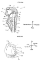
FIG. 1A is a perspective view of an outer appearance of a shift operation device, andFIG. 1B is an illustration showing an inner structure of a lever knob; -
FIG. 2A is a cross sectional view ofFIG. 1A taken along X-X line, andFIG. 2B is an enlarged view of a hollow portion; -
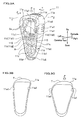
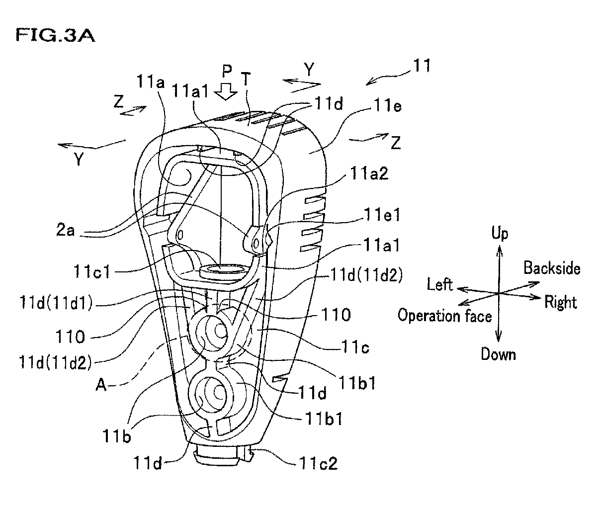
FIG. 3A is a perspective view showing a core of a lever knob according to an embodiment of the present invention,FIG. 3B is an illustration of an exterior portion as seen from an operation face side, andFIG. 3C is an illustration showing a deformation of the exterior portion; -
FIG. 4A is a cross sectional view ofFIG. 3A taken along Y-Y line, andFIG. 4B is a schematic illustration showing a state in that a core deforms at a thin portion; -
FIG. 5A is a cross sectional view ofFIG. 3A taken along Z-Z line, which is a backside of a core as seen from an operation face side, andFIG. 5B is a schematic illustration showing a state that the core deforms at a weak portion on the backside of the core; -
FIG. 6 is an enlarged view of an A portion ofFIG. 3A ; and -
FIG. 7 is a graph showing a relationship between a load to be applied on a core and an amount of deformation of the core. -
- 1 Lever knob
- 5 Lever shaft
- 10 Outer
- 11 Core
- 11a Hollow portion
- 11a1 Sidewall (outer circumferential portion)
- 11b Screw cramp portion (cylindrical boss)
- 11b1 Cylindrical portion
- 11c Insertion portion
- 11d Stiffening rib
- 11e Exterior portion (outer periphery portion)
- 11e1 V-shaped groove (second weak portion, concave groove)
- 11f Thin portion
- 11g Space portion
- 11h Groove portion
- 11s Outer wall surface
- 13 Screw (fixing member, screw member)
- 100 Shift operation device
- 110 Cut-out groove (first weak portion)
- T Vertex portion
- P Load
- Hereinafter, a preferred embodiment of the present invention will be explained in detail by referring to drawings as appropriate.
FIG. 1A is a perspective view of an outer appearance of a shift operation device, andFIG. 1B is an illustration showing an inner structure of a lever knob. As shown inFIG. 1A , ashift operation device 100 of an automatic transmission according to the present embodiment is provided with, for example, alever knob 1 that a driver grips on an upper end portion of alever shaft 5. Thelever knob 1 includes ashift button 2 which releases a shift lock of theshift operation device 100 and anoverdrive button 3 which allows switching ON/OFF of an overdrive mode, and anouter cover 4 is fixed on thelever knob 1 so as to cover an inner structure of thelever knob 1. - As shown in
FIG. 1B , thelever knob 1 is formed in such a manner that an outer 10 made of, for example, styrene-based thermoplastic elastomer covers a core 11 made of, for example, polyacetal. Ahollow portion 11a is formed by a sidewall 11a1 of the core 11 on a side of a vertex portion T of the outer 10 in order to reduce a weight of thelever knob 1 and secure a space for housing theshift button 2.
The sidewall 11a1 is disposed so as to surround thehollow portion 11a to ensure strength of thelever knob 1. Hereinafter, an up-and-down direction of thelever knob 1 is set so that a side of the vertex portion T of the outer 10 is the upper side.
In addition, a side on which theshift button 2 is arranged is named as an operation face, and the opposite side thereof is named as a backside. -
FIG. 2A is a cross sectional view ofFIG. 1A taken along X-X line. As shown inFIG. 2A , aninsertion portion 11c having a space portion 11c1 into which a levermain body 15 that is an axial portion of thelever shaft 5 is inserted is formed below the core 11 so as to extend downward from thehollow portion 11a. In addition, the levermain body 15 is inserted into theinsertion portion 11c so that an upper end of the levermain body 15 is located below thehollow portion 11a. That is, thehollow portion 11a is formed on the upper end side of thelever shaft 5.
The levermain body 15 that is inserted into theinsertion portion 11c is fixed to theinsertion portion 11c with screws (screw members) 13 which are fitted up in a direction perpendicular to an axial direction of the levermain body 15, that is, the axial direction of theshaft 5. For this purpose, ascrew cramp portion 11b is formed in theinsertion portion 11c of thecore 11. - As shown in
FIG. 1B , thescrew cramp portion 11b is formed so that thescrew 13 is inserted into a cylindrical boss which is formed in theinsertion portion 11c (seeFIG. 2A ), and includes a cylindrical portion 11b1 which is formed so as to surround thescrew 13 and a through-hole not shown that a screw portion of thescrew 13 passes though. Namely, thescrew cramp portion 11b is the cylindrical boss. - A screw hole not shown with which the screw portion of the
screw 13 is screwed together is formed in the levermain body 15, and as shown inFIG. 2A , thecore 11 is fixed to the levermain body 15 with thescrew 13.
Meanwhile, thelever shaft 5 may be formed in such a manner that a levermain body 15 exposed outside from the outer 10 is covered by acover member 15a made of, for example, resin as shown inFIG. 2A . - The
insertion portion 11c is formed so as to connect to a lower side of the sidewall 11a1 (seeFIG. 2B ) of thehollow portion 11a, and the space portion 11c1 of theinsertion portion 11c is formed passing through the side wall 11a1. Namely, the space portion 11c1 of theinsertion portion 11c is formed so as to communicate with thehollow portion 11a. - As shown in
FIG. 2A , thelever shaft 5 of the shift operation device 100 (seeFIG. 1A ) is a member connecting between an automatic transmission, not shown, and thelever knob 1, and includes the levermain body 15 having, for example, a pipe shape. Arod 14 for releasing a shift lock is provided in the space portion of the levermain body 15 of thelever shaft 5 in such a manner that therod 14 freely moves through the space portion in the up-and-down direction, and an upper end of therod 14 is projected into thehollow portion 11a of thecore 11.
In addition, thehollow portion 11a of thecore 11 is provided with theshift button 2 which moves therod 14 in the up-and-down direction. -
FIG. 2B is an enlarged view of the hollow portion. As shown inFIG. 2B , ahinge portion 2a supporting theshift button 2 is formed standing in thehollow portion 11a ranging from a back side of theexterior portion 11e (seeFIG. 3A ) forming an outer appearance of a backside of the core 11 to the up-and-down direction. Twohinge portions 2a described above are formed so as to sandwich theshift button 2, and theshift button 2 is swingably supported by the twohinge portions 2a through arotation shaft 2b.
In addition, in order to avoid interference with a projecting end portion of therotation shaft 2b from thehinge portion 2a, two recesses 11a2 are formed in the sidewall 11a1. - As shown in
FIG. 2A , anarm 2c which operates together with theshift button 2 is provided in theshift button 2, and if theshift button 2 swings around therotation shaft 2b, thearm 2c swings together with theshift button 2 around therotation shaft 2b. In the embodiment, thearm 2c is configured in such a manner that if theshift button 2 is pushed toward a back side of thelever knob 1, thearm 2c moves downward. In addition, the upper end of therod 14 and thearm 2c are configured to come in contact with each other, and if theshift button 2 rotates in a direction that theshift button 2 is pushed into thecore 11, therod 14 moves downward by thearm 2c.
Namely, if the driver operates theshift button 2 to be pushed into thelever knob 1, therod 14 moves downward. - Then, if the shift operation device 100 (see
FIG. 1A ) is configured so that a shift lock is released when therod 14 moved downward, the shift lock of theshift operation device 100 is released if the driver operates theshift button 2. In addition, if therod 14 is configured to be pushed upward by a pushing means not shown, thearm 2c is pushed upward by therod 14, and theshift button 2 is pushed in a direction to project toward the operation face from thelever knob 1. - In addition, an
overdrive button 3 is provided in thelever knob 1. For example, apush switch 3a which switches ON/OFF of an electric connection may be used for theoverdrive button 3. Namely, theoverdrive button 3 may be provided in such a manner that thepush switch 3a is fixed to, for example, thecore 11 by a fixing means not shown so that the operation portion protrudes from the operation face side of thelever knob 1 and the driver can operate the operation portion. - Meanwhile, common technologies may be used for the shift lock and the overdrive button 3 (see
FIG. 2A ) of the shift operation device 100 (seeFIG. 1A ) ,and the explanation thereof in detail will be omitted.
In addition, a method for mounting theouter cover 4 shown inFIG. 2A is not limited, and for example, by forming an engagement click not shown in theouter cover 4 and an engagement hole not shown in thecore 11, the engagement click in theouter cover 4 may be engaged with the engagement hole in thecore 11. -
FIG. 1A, FIG. 1B ,FIG. 2A, and FIG. 2B exemplify a selector lever of an automatic transmission, as the shift operation device 100 (seeFIG. 1A ). When the embodiment of the present invention is applied to a shift lever of a manual transmission, theoverdrive button 3 including thepush switch 3a, theshift button 2, thearm 2c, and therod 14 which are shown inFIG. 2A may be eliminated. In addition, thehinge portion 2a (seeFIG. 2B ) supporting theshift button 2 may be eliminated. In this case, the recess 11a2 may be formed as a weak portion described later. -
FIG. 3A is a perspective view showing a core of a lever knob according to the embodiment of the present invention,FIG. 3B is an illustration of an exterior portion as seen from an operation face side, andFIG. 3C is an illustration showing a deformation of the exterior portion. As shown inFIG. 3A , in thecore 11, theexterior portion 11e which is a box having a bottom and whose operation face side is opened forms an outer appearance of a backside of the core 11, and, for example, thehollow portion 11a, the twoscrew cramp portions insertion portion 11c are formed inside the opening of theexterior portion 11e.
In the upper side (side of vertex portion T) inside the opening of theexterior portion 11e, the sidewall 11a1 stands toward the operation face side from the backside to form thehollow portion 11a having substantially a rectangular shape as seen from the operation face side. Theinsertion portion 11c is formed on the lower side of the sidewall 11a1.
Theexterior portion 11e and the sidewall 11a1 form an outer circumferential portion. - On the back side inside the opening of the
exterior portion 11e, theinsertion portion 11c is formed as a ridge protrusion extending in the up-and-down direction. Theinsertion portion 11c is formed so that one end of the ridge protrusion is connected to the lower side of the sidewall 11a1, and a space portion 11c1 into which the lever main body 15 (seeFIG. 2A ) is inserted is formed in the ridge protrusion along the protrusion. The space portion 11c1 of theinsertion portion 11c is formed so as to penetrate the sidewall 11a1, and thehollow portion 11a communicates with the space portion 11c1 of theinsertion portion 11c.
In addition, the other end, which is not connected to the sidewall 11a1, of theinsertion portion 11c may be projected from the lower side of theexterior portion 11e to form, for example, an engagement portion 11c2 engaging with acover member 15a (seeFIG. 2A ) covering the lever main body 15 (seeFIG. 2A ). - In the ridge protrusion of the
insertion portion 11c, for example, twoscrew cramp portions 11b each consisting of a cylindrical boss are arranged along theinsertion portion 11c so as to open to the operation face side. That is, the sidewall 11a1 and thescrew cramp portions insertion portion 11c. In other words, the sidewall 11a1 and thescrew cramp portions FIG. 2A ) to be inserted into theinsertion portion 11c, that is, in the axial direction of the lever shaft 5 (seeFIG. 2A ). - As described above, the
screw cramp portion 11b consists of a cylindrical boss, and includes a cylinder portion 11b1 surrounding ascrew 13 shown inFIG. 2A . The cylindrical portion 11b1 of the upperscrew cramp portion 11b and the cylindrical portion 11b1 of the lowerscrew cramp portion 11b are connected by astiffening rib 11d which is formed on a line connecting between substantially centers of respective screw cramp portions.
In addition, the cylindrical portion 11b1 of the lowerscrew cramp portion 11b is connected to theexterior portion 11e by the stiffeningrib 11d.
Further, an upper portion of the sidewall 11a1 forming thehollow portion 11a is connected to theexterior portion 11e by the stiffeningrib 11d. - The
screw cramp portion 11b consists of a cylindrical boss opening to the operation face side, and the sidewall 11a1 stands toward the operation face side from a back side of theexterior portion 11e. Therefore, the sidewall 11a1 is formed to stand in a height direction of thescrew cramp portion 11b.
Then, the cylindrical portion 11b1 of the upperscrew cramp portion 11b is connected to the lower side of the sidewall 11a1 forming thehollow portion 11a by the stiffeningrib 11d.
The cylindrical portion 11b1 of theupper screw portion 11b and the sidewall 11a1 are connected by asingle stiffening rib 11d (center rib 11d1) which is formed on a line along theinsertion portion 11c through substantially the center of thescrew cramp portion 11b and by two stiffeningribs FIG. 2A ), that is, in the axial direction of the lever shaft 5 (seeFIG. 2A ). - In the
core 11, the lower side of the sidewall 11a1 forming thehollow portion 11a and the cylindrical portion 11b1 of the upperscrew cramp portion 11b are connected by the stiffeningrib 11d, the cylindrical portion 11b1 of the upperscrew cramp portion 11b and the cylindrical portion 11b1 of the lowerscrew cramp portion 11b are connected by the stiffeningrib 11b, and the cylindrical portion 11b1 of the lowerscrew cramp portion 11b and theexterior portion 11e are connected by the stiffeningrib 11d. In addition, as shown inFIG. 3A , theexterior portion 11e and the upper side of the sidewall 11a1 forming thehollow portion 11a are connected by the stiffeningrib 11d.
The structure as described above ensures a strength of the core 11 against a load operating in the axial direction of the lever main bogy 15 (seeFIG. 2A ), that is, in the axial direction (hereinafter, referred to as up-and-down direction) of the lever shaft 5 (seeFIG. 2A ).
In addition, a V-shaped cut-outgroove 110 formed in a height direction of the cylindrical portion 11b1 is disposed in a connection portion between the center rib 11d1 and the cylindrical portion 11b1 of the upperscrew cramp portion 11b. The V-shaped cut-outgroove 110 will be described later in detail. - Meanwhile, the number of the
screw cramp portions 11b is not limited, and may be one, or may be more than two. If the number of thescrew cramp portions 11b is more than two, the cylindrical portion 11b1 of each of the screw cramp portions may be connected by the stiffeningrib 11d.
In addition, thescrew cramp portions 11b which is formed to be closest to the sidewall 11a1 of thehollow portion 11a and the lower side of the sidewall 11a1 may be connected by one center rib 11d1 and two side ribs 11d2, 11d2. - The lever knob 1 (see
FIG. 1A ) according to the embodiment of the present invention is provided with a weak portion in the core 11 (seeFIG. 1B ), and if a load (for example, impact load) exceeding a predetermined value and operating in the up-and-down direction is applied in the axial direction of the lever shaft 5 (seeFIG. 2A ) from the vertex portion T of thelever knob 1, thecore 11 is crashed at the weak portion to absorb the load.
Meanwhile, the predetermined value may be set as appropriated based on, for example, vehicle performances required for the vehicle provided with the shift operation device 100 (seeFIG. 1A ). - As shown in
FIG. 3A , on a wall inside the opening of theexterior portion 11e of the core 11 according to the embodiment, a V-shaped groove (concave groove) 11e1 is formed at a position, for example, facing the recess 11a2 of the sidewall 11a1 in a groove-like shape toward the back side from the operation face side. Namely, the V-shaped groove 11e1 is formed along a standing direction of the sidewall 11a1. The V-shaped groove 11e1 may be one, or may be more than one. The V-shaped groove 11e1 described above is disposed on each side of thehollow portion 11a as seen from the operation face side as shown, for example, inFIG. 3A and FIG. 3B .
Meanwhile, a depth of the V-shaped groove 11e1 from the operation face may be set as appropriate based on, for example, the strength required for thecore 11. - If a load P operating in the up-and-down direction is applied to the vertex portion T of the
exterior portion 11e, a stress occurs in theexterior portion 11e. In this case, as shown inFIG. 3B , a stress concentration occurs in the formed V-shaped groove 11e1, and as shown inFIG. 3C , deformation and breaking of theexterior portion 11e originate from the V-shaped groove 11e1.
Since a portion of the V-shaped groove 11e1 is formed to be thin, as shown inFIG. 3A , a thin portion due to theexterior portion 11e is formed around thehollow portion 11a. In addition, the V-shaped groove 11e1 causes deformation and breaking of theexterior portion 11e, and accordingly, the V-shaped groove 11e1 forms a weak portion (second weak portion). - In addition, the core 11 according to the embodiment is provided with a thin portion in a standing portion of the sidewall 11a1.
FIG. 4A is a cross sectional view ofFIG. 3A taken along Y-Y line, andFIG. 4B is a schematic illustration showing a state in that a core deforms at a thin portion. As shown inFIG. 4A , thehollow portion 11a is formed so that an outer periphery portion including theexterior portion 11e of thecore 11 becomes to be thin. In addition, a connection portion between the sidewall 11a1 of thehollow portion 11a and theexterior portion 11e is formed to be further thinner to form athin portion 11f. Namely, the standing portion of the sidewall 11a1 of thecore 11 is formed to be thin. - If the load P operating in the up-and-down direction is applied to the vertex portion T of the
exterior portion 11e, a stress occurs in theexterior portion 11e, and a stress concentration occurs at the connection portion between the sidewall 11a1 and theexterior portion 11e. In the embodiment, thethin portion 11f is disposed in the connection portion where the stress concentration occurs between the sidewall 11a1 and theexterior portion 11e so that the deformation and breaking of the core 11 originate from thethin portion 11f. - As shown in
FIG. 4B , if the load P operating in the up-and-down direction is applied to the vertex portion T of the core 11 configured as described above, a stress occurs in thecore 11, and stress concentrations occur at thethin portion 11f and at a vertex angle portion of the V-shaped groove 11e1 (seeFIG. 3A ) formed in theexterior portion 11e. In addition, the stress occurred in thecore 11 is transferred to the sidewall 11a1, and a stress concentration occurs at the recess 11a2 (seeFIG. 3A ). If the stress occurred in thecore 11 exceeds the predetermined value, the recess 11a2 of the sidewall 11a1 deforms in the up-and-down direction to be crashed and broken.
In addition, as shown inFIG. 3C , theexterior portion 11e deforms to break at the V-shaped groove 11e1, as well as thethin portion 11f breaks as shown inFIG. 4B . As a result, the load P, which was applied to thecore 11, operating in the up-and-down direction is absorbed through the breaking of thecore 11.
Meanwhile, when the load P operating in the up-and-down direction is applied to the vertex portion T of thecore 11 and the core 11 breaks at the weak portions, the vertex portion T of thecore 11 deforms to be depressed into thehollow portion 11a. Therefore, thehollow portion 11a serves to absorb the deformation of thecore 11. - The core 11 according to the embodiment may have a weak portion on the back side thereof.
FIG. 5A is a cross sectional view ofFIG. 3A taken along Z-Z line, which is a backside of a core as seen from the operation face side, andFIG. 5B is a schematic illustration showing a state in that the core deforms at a weak portion on the back side of the core. As shown inFIG. 5A , a plurality ofspace portions 11g (three inFIG. 5A ) are formed on the back side of theexterior portion 11e of the core 11 by emptying theexterior portion 11e. In addition, a plurality ofgroove portions 11h (four inFIG. 5A ) are formed on anouter wall surface 11s of theexterior portion 11e in a direction, for example, toward the back side from the operation face side.
Thespace portions 11g and thegroove portions 11h formed as described above form weak portions in the case that the load P operating in the up-and-down direction is applied to the vertex portion T of thecore 11. - Namely, a thin portion is formed in the
core 11 by forming the plurality of thegroove portions 11h on theouter wall surface 11s of theexterior portion 11e of thecore 11. Then, if the load P operating in the up-and-down direction is applied to the vertex portion T, the thin portions due to thegroove portions 11h and thespace portions 11g deform to form origins of breaking of the core 11 as shown inFIG. 5B . - In addition, in the embodiment, a weak portion is also formed in the
screw cramp portion 11b (seeFIG. 3A ) of the core 11 (seeFIG. 3A ). -
FIG. 6 is an enlarged view of an A portion ofFIG. 3A . As shown inFIG. 6 , V-shaped cut-outgrooves 110 which are formed in the height direction of a boss forming thescrew cramp portion 11b are formed in the connection portion between the cylindrical portion 11b1 of the upperscrew cramp portion 11b and the center rib 11d1. By forming the V-shaped cut-outgrooves 110 as described above, the cylindrical portion 11b1 at the connection portion connecting with the center rib 11d1 can be formed thinner than the other portions of the cylindrical portion 11b1.
For example, when the load P operating in the up-and-down direction is applied to the center rib 11d1 and a stress occurs in the connection portion between the center rib 11d1 and the cylindrical portion 11b1 by the load, stress concentrations occur at the thin portions of the cylindrical portion 11b1. - Then, if a stress exceeding a predetermined value occurs in the connection portion between center rib 11d1 and the cylindrical portion 11b1, the cylindrical portion 11b1 of the
screw cramp portion 11b is broken by a stress concentration occurred in the thin portion. In addition, since the cut-outgrooves 110 are formed in a V shape, a large stress concentration occurs at the V-shaped vertex angle portion, and accordingly, the cylindrical portion 11b1 is effectively broken. - As shown in
FIG. 3A , if the load P operating in the up-and-down direction is applied to the vertex portion T of the core 11, a stress occurs in thecore 11, and the stress is transferred to the inner structure of the core 11 to generate a stress operating in the up-and-down direction in the center rib 11d1. - Therefore, if the load P operating in the up-and-down direction and exceeding a predetermined value is applied to the vertex portion T of the core 11 (see
FIG. 3A ), a stress operating in the up-and-down direction and exceeding a predetermined value occurs in the center rib 11d1. Then, the upperscrew cramp portion 11b breaks starting from the cut-outgrooves 110 to absorb the load applied to thecore 11.
Accordingly, the V-shaped cut-outgrooves 110 also form weak portions (first weak portion) of thecore 11.
Meanwhile, a shape of the cut-outgrooves 110 is not limited to a V shape, and, for example, a rectangular shape or a semicircular shape may be used. Other than those, the shape is not limited as long as at least one part of the cylindrical portion 11b1 is formed to be thinner than the other parts. -
FIG. 7 is a graph showing a relationship between a load applied on a core and an amount of deformation of the core. As shown inFIG. 7 , when the load P (compressive load) operating in the up-and-down direction is applied to the vertex portion T of the core 11 (seeFIG. 3A ) and increased, a deformation amount Δ1 of the core 11 increases as the load P increases. If the applied load P reaches P1, thescrew cramp portion 11b (seeFIG. 3A ) of the core 11 breaks at the cut-out grooves 110 (seeFIG. 3A ).
With respect to thehollow portion 11a (seeFIG. 3A ), since the outer circumferential portion of thecore 11 is formed to be thin, thecore 11 deforms to expand to right and left direction in thehollow portion 11a. Therefore, a force which deforms the cut-outgrooves 110 in the right and left direction is increased, thereby resulting in easy breaking of thecore 11. In addition, by forming the V-shaped grooves 11e1 (seeFIG. 3A ) in theexterior portion 11e, thecore 11 expands easily to right and left, thereby resulting in further easy breaking of thecore 11. - When the load P applied to the
core 11 is further increased, the deformation amount Δ1 of the core 11 increases, and if the applied load P reaches P2 which is larger than P1, the vertex portion T of thecore 11 deforms to be depressed into thehollow portion 11a to be broken, as shown inFIG. 4B . - As described above, a strength of the
core 11 is designed in such a manner that when the applied load P to the core 11 (seeFIG. 4A ) is increased, thescrew cramp portion 11b (seeFIG. 3A ) breaks first at the cut-out grooves 110 (seeFIG. 3A ), and the applied load p is further increased, thehollow portion 11a (seeFIG. 3A ) breaks next at the V-shaped grooves 11e1 (seeFIG. 3A ) of theexterior portion 11e and at thethin portions 11f (seeFIG. 4A ). As a result, if the load P applied to the vertex portion T of thecore 11 is, for example, an impact load, the core 11 can absorb the initial impact load through breaking of thescrew cramp portion 11b, and the secondary impact load following the initial impact load through the breaking of thehollow portion 11a. - Namely, the shift operation device 100 (see
FIG. 1A ) according to the embodiment is provided with the weak portions in the core 11 (seeFIG. 3A ) forming the lever knob 1 (seeFIG. 1A ), and when a load operating in the up-and-down direction and exceeding the predetermined value is applied to the vertex portion of thelever knob 1 as an impact load, the inner structure of thelever knob 1 breaks. Therefore, the initial impact load and the secondary impact load following the initial impact load can be effectively absorbed through the breaking of thelever knob 1, accordingly. - In addition, by providing the
hollow portion 11a (seeFIG. 3A ), an outer periphery portion including theexterior portion 11e (seeFIG. 3A ) of the core 11 (seeFIG. 3A ) is formed to be thin so as to expand easily to right and left, thereby, a breaking of the core 11 through deformation of the core 11 in the right and left direction can be easily achieved by expansion of thehollow portion 11a and the weak portions. Therefore, the lever knob 1 (seeFIG. 1A ) can absorb the impact load operating in the axial direction of the lever shaft 5 (seeFIG. 1A ) with a simple structure.
In addition, since thecore 11 of thelever knob 1 has a structure that easily deforms in the right and left direction to be broken at thehollow portion 11a, the connection portion between the center rib 11d1 (seeFIG. 6 ) and the cylindrical portion 11b1 easily breaks to right and left at the cut-out grooves 110 (seeFIG. 6 ). As described above, an impact load operating in the axial direction of thelever shaft 5 can be absorbed through the breaking of the connection portion between the center rib 11d1 and the cylindrical portion 11b1.
Furthermore, since thecore 11 deforms in the right and left direction to be broken by a load in the axial direction, a structure such as a shift button 2 (seeFIG. 2B ) may be arranged in thehollow portion 11a. - It is noted that the load P1 with which the
screw cramp portion 11b (seeFIG. 3A ) breaks at the cut-out grooves 110 (seeFIG. 3A ), the load P2 with which thehollow portion 11a (seeFIG. 3A ) breaks at the V-shaped grooves 11e1 (seeFIG. 3A ) and at thethin portion 11f (seeFIG. 4A ), and the deformation amount Δ1 by the applied load P are not limited specifically, and may be set as appropriate based on vehicle performances required for the vehicle. - In addition, in the embodiment, the
screw cramp portion 11b (seeFIG. 3A ) breaks first at the cut-out grooves 110 (seeFIG. 3A ), and if the applied load P is further increased, thehollow portion 11a (seeFIG. 3A ) breaks at the V-shaped grooves 11e1 (seeFIG. 3A ) of theexterior portion 11e and at thethin portions 11f (seeFIG. 4A ). However, the order of breaking is not limited to this, and thehollow portion 11a (seeFIG. 3A ) may break first at the V-shaped grooves 11e1 of theexterior portion 11e and at thethin portions 11f.
Claims (13)
- A shift operation device, comprising:a lever shaft supported by a vehicle;a lever knob provided in an upper end portion of the lever shaft;a core provided inside the lever knob and fixed to the upper end portion of the lever shaft;a connection member for fixing the core to the lever shaft; anda hollow portion which is provided on an upper side of the lever shaft than the connection member and inside the core, an outer periphery portion of the core being formed to be thin by disposing the hollow portion,wherein a first weak portion which is weak against a load operating in an axial direction of the lever shaft is formed between the hollow portion and the connection member.
- The shift operation device according to claim 1,
wherein the connection member comprises a screw; and
wherein the core comprises:a cylindrical boss into which the screw is inserted in a direction perpendicular to the axial direction of the lever shaft; anda sidewall standing in a height direction of the cylindrical boss and forming the hollow portion,wherein the cylindrical boss and the sidewall are formed in line in the axial direction of the lever shaft and a cylindrical portion of the cylindrical boss and the sidewall are connected by a stiffening rib,wherein the first weak portion is disposed in a connection portion between the cylindrical portion and the stiffening rib. - The shift operation device according to claim 1,
wherein the core is provided with a second weak portion which is weak against a load operating in the axial direction of the lever shaft in the outer periphery portion of the core forming a surrounding of the hollow portion. - The shift operation device according to claim 2,
wherein the core is provided with a second weak portion which is weak against a load operating in the axial direction of the lever shaft in the outer periphery portion of the core forming a surrounding of the hollow portion. - The shift operation device according to claim 3,
wherein the core is provided with the second weak portion by forming a concave groove in the outer periphery portion on each of right and left sides of the hollow portion. - The shift operation device according to claim 4,
wherein the core is provided with the second weak portion by forming a concave groove along a standing direction of the sidewall in the outer periphery portion on each of right and left sides of the hollow portion. - The shift operation device according to any one of claims 2, 4 and 6,
wherein a thin portion which is weak against a load operating in the axial direction of the lever shaft is disposed in a connection portion between the sidewall and the outer periphery portion. - The shift operation device according to any one of claims 2 to 6,
wherein a space portion which is weak against a load operating in the axial direction of the lever shaft is disposed by emptying a part of the outer periphery portion. - The shift operation device according to claim 7,
wherein a space portion which is weak against a load operating in the axial direction of the lever shaft is disposed by emptying a part of the outer periphery portion. - The shift operation device according to any one of claims 2 to 6,
wherein a groove portion which is weak against a load operating in the axial direction of the lever shaft is disposed on an outer wall surface of the outer periphery portion. - The shift operation device according to claim 7,
wherein a groove portion which is weak against a load operating in the axial direction of the lever shaft is disposed on an outer wall surface of the outer periphery portion. - The shift operation device according to claim 8,
wherein a groove portion which is weak against a load operating in the axial direction of the lever shaft is disposed on an outer wall surface of the outer periphery portion. - The shift operation device according to claim 9,
wherein a groove portion which is weak against a load operating in the axial direction of the lever shaft is disposed on an outer wall surface of the outer periphery portion.
Applications Claiming Priority (2)
| Application Number | Priority Date | Filing Date | Title |
|---|---|---|---|
| JP2008086479 | 2008-03-28 | ||
| PCT/JP2009/056392 WO2009119851A1 (en) | 2008-03-28 | 2009-03-27 | Shift operation device |
Publications (3)
| Publication Number | Publication Date |
|---|---|
| EP2258577A1 true EP2258577A1 (en) | 2010-12-08 |
| EP2258577A4 EP2258577A4 (en) | 2011-05-25 |
| EP2258577B1 EP2258577B1 (en) | 2013-10-23 |
Family
ID=41114037
Family Applications (1)
| Application Number | Title | Priority Date | Filing Date |
|---|---|---|---|
| EP09723885.1A Not-in-force EP2258577B1 (en) | 2008-03-28 | 2009-03-27 | Shift operation device |
Country Status (5)
| Country | Link |
|---|---|
| US (1) | US8464606B2 (en) |
| EP (1) | EP2258577B1 (en) |
| JP (1) | JP5291702B2 (en) |
| CN (1) | CN101980884B (en) |
| WO (1) | WO2009119851A1 (en) |
Cited By (1)
| Publication number | Priority date | Publication date | Assignee | Title |
|---|---|---|---|---|
| FR3117262A1 (en) * | 2020-12-09 | 2022-06-10 | Crouzet | PADDLE BUTTON |
Families Citing this family (7)
| Publication number | Priority date | Publication date | Assignee | Title |
|---|---|---|---|---|
| WO2010039845A2 (en) * | 2008-09-30 | 2010-04-08 | Dura Global Technologies, Inc. | Shifter assembly including display and actuation for driver control |
| EP2570701B1 (en) * | 2011-09-14 | 2013-11-20 | Kongsberg Automotive AB | Knob assembly |
| US20130133469A1 (en) * | 2011-11-28 | 2013-05-30 | Embraer S.A. | Sidestick controller grip |
| KR101355617B1 (en) * | 2012-10-26 | 2014-01-27 | 현대자동차주식회사 | Shift lever |
| USD789265S1 (en) * | 2016-04-28 | 2017-06-13 | Pilot, Inc. | Shift knob cover |
| KR102699019B1 (en) * | 2016-12-06 | 2024-08-23 | 현대자동차주식회사 | Shift lever assembly of vehicle |
| JP6738270B2 (en) * | 2016-12-26 | 2020-08-12 | 株式会社東海理化電機製作所 | Shift device |
Family Cites Families (18)
| Publication number | Priority date | Publication date | Assignee | Title |
|---|---|---|---|---|
| US3071023A (en) * | 1960-02-09 | 1963-01-01 | Happich Gmbh Gebr | Non-injurious resilient actuating knobs for use in automotive vehicles and the like |
| DE1255522B (en) * | 1963-06-24 | 1967-11-30 | Happich Gmbh Gebr | Control button, especially for motor vehicle window cranks |
| US3561281A (en) * | 1968-09-06 | 1971-02-09 | Thomas Wilfert | Safety control lever |
| DE2003874C3 (en) * | 1970-01-29 | 1974-02-07 | Daimler-Benz Ag, 7000 Stuttgart | Manual shift lever, in particular center shift lever, articulated to a shift tube for the change gear of motor vehicles |
| DE2063371A1 (en) * | 1970-12-23 | 1972-07-13 | Wilhelm Neuscheler | SHIFT LEVER FOR THE TRANSMISSION OF A CAR |
| US3750492A (en) * | 1971-09-20 | 1973-08-07 | Holmes H Sr | Energy absorbing shift lever |
| FR2673401B1 (en) * | 1991-03-01 | 1995-07-28 | Valeo | POLARIZED GEAR LEVER FOR CONTROLLING A GEAR CHANGE DEVICE, ESPECIALLY FOR MOTOR VEHICLES. |
| JPH1067245A (en) * | 1996-08-27 | 1998-03-10 | Honda Motor Co Ltd | Transmission operation lever |
| US6286385B1 (en) * | 1997-12-02 | 2001-09-11 | Kabushiki Kaisha Tokai-Rika-Denki-Seisakusho | Shift lever device |
| JP3693768B2 (en) * | 1996-10-11 | 2005-09-07 | 株式会社東海理化電機製作所 | Shift lever device |
| JP4087493B2 (en) * | 1998-03-30 | 2008-05-21 | 富士機工株式会社 | Automatic transmission shift device |
| JP3958917B2 (en) * | 2000-07-18 | 2007-08-15 | 株式会社アツミテック | Speed change operation device for vehicle |
| DE10158934A1 (en) * | 2001-12-03 | 2003-06-12 | Zf Lemfoerder Metallwaren Ag | shift knob |
| JP2004142651A (en) | 2002-10-25 | 2004-05-20 | Suzuki Motor Corp | Shift knob structure |
| JP4101703B2 (en) * | 2003-06-11 | 2008-06-18 | 富士機工株式会社 | Shift lever device |
| JP4395489B2 (en) | 2006-05-08 | 2010-01-06 | 株式会社東海理化電機製作所 | Shift lever device |
| JP2009018601A (en) * | 2007-07-10 | 2009-01-29 | Atsumi Tec:Kk | Speed change operation device for vehicle |
| US7997548B2 (en) * | 2007-12-31 | 2011-08-16 | Honda Motor Co., Ltd. | Vehicle shifter mounting bracket system and method |
-
2009
- 2009-03-27 CN CN200980110988.4A patent/CN101980884B/en not_active Expired - Fee Related
- 2009-03-27 JP JP2010505874A patent/JP5291702B2/en not_active Expired - Fee Related
- 2009-03-27 EP EP09723885.1A patent/EP2258577B1/en not_active Not-in-force
- 2009-03-27 WO PCT/JP2009/056392 patent/WO2009119851A1/en not_active Ceased
- 2009-03-27 US US12/934,692 patent/US8464606B2/en not_active Expired - Fee Related
Non-Patent Citations (2)
| Title |
|---|
| No further relevant documents disclosed * |
| See also references of WO2009119851A1 * |
Cited By (3)
| Publication number | Priority date | Publication date | Assignee | Title |
|---|---|---|---|---|
| FR3117262A1 (en) * | 2020-12-09 | 2022-06-10 | Crouzet | PADDLE BUTTON |
| WO2022122570A1 (en) | 2020-12-09 | 2022-06-16 | Crouzet | Paddle button |
| US12535844B2 (en) | 2020-12-09 | 2026-01-27 | Crouzet | Paddle button |
Also Published As
| Publication number | Publication date |
|---|---|
| CN101980884A (en) | 2011-02-23 |
| CN101980884B (en) | 2014-04-23 |
| EP2258577A4 (en) | 2011-05-25 |
| EP2258577B1 (en) | 2013-10-23 |
| JP5291702B2 (en) | 2013-09-18 |
| US20110023646A1 (en) | 2011-02-03 |
| WO2009119851A1 (en) | 2009-10-01 |
| US8464606B2 (en) | 2013-06-18 |
| JPWO2009119851A1 (en) | 2011-07-28 |
Similar Documents
| Publication | Publication Date | Title |
|---|---|---|
| EP2258577A1 (en) | Shift operation device | |
| JP2009129871A (en) | Multidirectional operation switch device | |
| US20170114892A1 (en) | Shift lever device | |
| JP2014216262A (en) | Key switch device and keyboard | |
| JP6985878B2 (en) | Switch device | |
| JP4598721B2 (en) | Operation key parts | |
| US6072134A (en) | Key switch device | |
| JP5407636B2 (en) | In-vehicle combined operation switch | |
| JP2008047351A (en) | Key switch device and keyboard having key switch device | |
| JP2014028610A (en) | Shift lever device | |
| JP2023111813A (en) | Multi-directional operation switch device | |
| EP1720186A2 (en) | Switch | |
| JP2008047351A5 (en) | ||
| US7361858B2 (en) | Swing switch | |
| JP4846662B2 (en) | Multi-directional operation switch | |
| JP4592456B2 (en) | Tumbler switch | |
| JP5657336B2 (en) | Shift lever unit | |
| JP4844836B2 (en) | Push button device | |
| JP2006059619A (en) | Vehicle-mounted pushbutton switch | |
| JP2020101633A (en) | Musical instrument | |
| JP2006049021A (en) | Button structure | |
| JP6776110B2 (en) | Seesaw switch structure | |
| IT202300021402A1 (en) | PUSH BUTTON SWITCH FOR MOTOR VEHICLES, ESPECIALLY FOR MOTOR VEHICLE DOOR PANELS | |
| JP2024141103A (en) | Temporary screw retention structure | |
| JP2001233077A (en) | Shift lever device |
Legal Events
| Date | Code | Title | Description |
|---|---|---|---|
| PUAI | Public reference made under article 153(3) epc to a published international application that has entered the european phase |
Free format text: ORIGINAL CODE: 0009012 |
|
| 17P | Request for examination filed |
Effective date: 20100928 |
|
| AK | Designated contracting states |
Kind code of ref document: A1 Designated state(s): AT BE BG CH CY CZ DE DK EE ES FI FR GB GR HR HU IE IS IT LI LT LU LV MC MK MT NL NO PL PT RO SE SI SK TR |
|
| AX | Request for extension of the european patent |
Extension state: AL BA RS |
|
| A4 | Supplementary search report drawn up and despatched |
Effective date: 20110429 |
|
| 17Q | First examination report despatched |
Effective date: 20110512 |
|
| DAX | Request for extension of the european patent (deleted) | ||
| GRAP | Despatch of communication of intention to grant a patent |
Free format text: ORIGINAL CODE: EPIDOSNIGR1 |
|
| INTG | Intention to grant announced |
Effective date: 20130611 |
|
| GRAS | Grant fee paid |
Free format text: ORIGINAL CODE: EPIDOSNIGR3 |
|
| GRAA | (expected) grant |
Free format text: ORIGINAL CODE: 0009210 |
|
| AK | Designated contracting states |
Kind code of ref document: B1 Designated state(s): AT BE BG CH CY CZ DE DK EE ES FI FR GB GR HR HU IE IS IT LI LT LU LV MC MK MT NL NO PL PT RO SE SI SK TR |
|
| REG | Reference to a national code |
Ref country code: GB Ref legal event code: FG4D |
|
| REG | Reference to a national code |
Ref country code: CH Ref legal event code: EP |
|
| REG | Reference to a national code |
Ref country code: AT Ref legal event code: REF Ref document number: 637364 Country of ref document: AT Kind code of ref document: T Effective date: 20131115 |
|
| REG | Reference to a national code |
Ref country code: IE Ref legal event code: FG4D |
|
| REG | Reference to a national code |
Ref country code: DE Ref legal event code: R096 Ref document number: 602009019615 Country of ref document: DE Effective date: 20131219 |
|
| REG | Reference to a national code |
Ref country code: NL Ref legal event code: VDEP Effective date: 20131023 |
|
| REG | Reference to a national code |
Ref country code: AT Ref legal event code: MK05 Ref document number: 637364 Country of ref document: AT Kind code of ref document: T Effective date: 20131023 |
|
| REG | Reference to a national code |
Ref country code: LT Ref legal event code: MG4D |
|
| PG25 | Lapsed in a contracting state [announced via postgrant information from national office to epo] |
Ref country code: FI Free format text: LAPSE BECAUSE OF FAILURE TO SUBMIT A TRANSLATION OF THE DESCRIPTION OR TO PAY THE FEE WITHIN THE PRESCRIBED TIME-LIMIT Effective date: 20131023 Ref country code: NO Free format text: LAPSE BECAUSE OF FAILURE TO SUBMIT A TRANSLATION OF THE DESCRIPTION OR TO PAY THE FEE WITHIN THE PRESCRIBED TIME-LIMIT Effective date: 20140123 Ref country code: BE Free format text: LAPSE BECAUSE OF FAILURE TO SUBMIT A TRANSLATION OF THE DESCRIPTION OR TO PAY THE FEE WITHIN THE PRESCRIBED TIME-LIMIT Effective date: 20131023 Ref country code: LT Free format text: LAPSE BECAUSE OF FAILURE TO SUBMIT A TRANSLATION OF THE DESCRIPTION OR TO PAY THE FEE WITHIN THE PRESCRIBED TIME-LIMIT Effective date: 20131023 Ref country code: SE Free format text: LAPSE BECAUSE OF FAILURE TO SUBMIT A TRANSLATION OF THE DESCRIPTION OR TO PAY THE FEE WITHIN THE PRESCRIBED TIME-LIMIT Effective date: 20131023 Ref country code: IS Free format text: LAPSE BECAUSE OF FAILURE TO SUBMIT A TRANSLATION OF THE DESCRIPTION OR TO PAY THE FEE WITHIN THE PRESCRIBED TIME-LIMIT Effective date: 20140223 Ref country code: HR Free format text: LAPSE BECAUSE OF FAILURE TO SUBMIT A TRANSLATION OF THE DESCRIPTION OR TO PAY THE FEE WITHIN THE PRESCRIBED TIME-LIMIT Effective date: 20131023 Ref country code: NL Free format text: LAPSE BECAUSE OF FAILURE TO SUBMIT A TRANSLATION OF THE DESCRIPTION OR TO PAY THE FEE WITHIN THE PRESCRIBED TIME-LIMIT Effective date: 20131023 |
|
| PG25 | Lapsed in a contracting state [announced via postgrant information from national office to epo] |
Ref country code: CY Free format text: LAPSE BECAUSE OF FAILURE TO SUBMIT A TRANSLATION OF THE DESCRIPTION OR TO PAY THE FEE WITHIN THE PRESCRIBED TIME-LIMIT Effective date: 20131023 Ref country code: ES Free format text: LAPSE BECAUSE OF FAILURE TO SUBMIT A TRANSLATION OF THE DESCRIPTION OR TO PAY THE FEE WITHIN THE PRESCRIBED TIME-LIMIT Effective date: 20131023 Ref country code: LV Free format text: LAPSE BECAUSE OF FAILURE TO SUBMIT A TRANSLATION OF THE DESCRIPTION OR TO PAY THE FEE WITHIN THE PRESCRIBED TIME-LIMIT Effective date: 20131023 Ref country code: AT Free format text: LAPSE BECAUSE OF FAILURE TO SUBMIT A TRANSLATION OF THE DESCRIPTION OR TO PAY THE FEE WITHIN THE PRESCRIBED TIME-LIMIT Effective date: 20131023 |
|
| PG25 | Lapsed in a contracting state [announced via postgrant information from national office to epo] |
Ref country code: PT Free format text: LAPSE BECAUSE OF FAILURE TO SUBMIT A TRANSLATION OF THE DESCRIPTION OR TO PAY THE FEE WITHIN THE PRESCRIBED TIME-LIMIT Effective date: 20140224 |
|
| REG | Reference to a national code |
Ref country code: DE Ref legal event code: R097 Ref document number: 602009019615 Country of ref document: DE |
|
| PG25 | Lapsed in a contracting state [announced via postgrant information from national office to epo] |
Ref country code: EE Free format text: LAPSE BECAUSE OF FAILURE TO SUBMIT A TRANSLATION OF THE DESCRIPTION OR TO PAY THE FEE WITHIN THE PRESCRIBED TIME-LIMIT Effective date: 20131023 |
|
| PG25 | Lapsed in a contracting state [announced via postgrant information from national office to epo] |
Ref country code: SK Free format text: LAPSE BECAUSE OF FAILURE TO SUBMIT A TRANSLATION OF THE DESCRIPTION OR TO PAY THE FEE WITHIN THE PRESCRIBED TIME-LIMIT Effective date: 20131023 Ref country code: IT Free format text: LAPSE BECAUSE OF FAILURE TO SUBMIT A TRANSLATION OF THE DESCRIPTION OR TO PAY THE FEE WITHIN THE PRESCRIBED TIME-LIMIT Effective date: 20131023 Ref country code: PL Free format text: LAPSE BECAUSE OF FAILURE TO SUBMIT A TRANSLATION OF THE DESCRIPTION OR TO PAY THE FEE WITHIN THE PRESCRIBED TIME-LIMIT Effective date: 20131023 Ref country code: CZ Free format text: LAPSE BECAUSE OF FAILURE TO SUBMIT A TRANSLATION OF THE DESCRIPTION OR TO PAY THE FEE WITHIN THE PRESCRIBED TIME-LIMIT Effective date: 20131023 Ref country code: RO Free format text: LAPSE BECAUSE OF FAILURE TO SUBMIT A TRANSLATION OF THE DESCRIPTION OR TO PAY THE FEE WITHIN THE PRESCRIBED TIME-LIMIT Effective date: 20131023 |
|
| PLBE | No opposition filed within time limit |
Free format text: ORIGINAL CODE: 0009261 |
|
| STAA | Information on the status of an ep patent application or granted ep patent |
Free format text: STATUS: NO OPPOSITION FILED WITHIN TIME LIMIT |
|
| PG25 | Lapsed in a contracting state [announced via postgrant information from national office to epo] |
Ref country code: DK Free format text: LAPSE BECAUSE OF FAILURE TO SUBMIT A TRANSLATION OF THE DESCRIPTION OR TO PAY THE FEE WITHIN THE PRESCRIBED TIME-LIMIT Effective date: 20131023 |
|
| 26N | No opposition filed |
Effective date: 20140724 |
|
| PG25 | Lapsed in a contracting state [announced via postgrant information from national office to epo] |
Ref country code: LU Free format text: LAPSE BECAUSE OF FAILURE TO SUBMIT A TRANSLATION OF THE DESCRIPTION OR TO PAY THE FEE WITHIN THE PRESCRIBED TIME-LIMIT Effective date: 20140327 |
|
| REG | Reference to a national code |
Ref country code: CH Ref legal event code: PL |
|
| REG | Reference to a national code |
Ref country code: DE Ref legal event code: R097 Ref document number: 602009019615 Country of ref document: DE Effective date: 20140724 |
|
| REG | Reference to a national code |
Ref country code: DE Ref legal event code: R084 Ref document number: 602009019615 Country of ref document: DE |
|
| REG | Reference to a national code |
Ref country code: GB Ref legal event code: 746 Effective date: 20141114 |
|
| REG | Reference to a national code |
Ref country code: FR Ref legal event code: ST Effective date: 20141128 |
|
| REG | Reference to a national code |
Ref country code: IE Ref legal event code: MM4A Ref country code: DE Ref legal event code: R084 Ref document number: 602009019615 Country of ref document: DE Effective date: 20141120 |
|
| PG25 | Lapsed in a contracting state [announced via postgrant information from national office to epo] |
Ref country code: IE Free format text: LAPSE BECAUSE OF NON-PAYMENT OF DUE FEES Effective date: 20140327 Ref country code: CH Free format text: LAPSE BECAUSE OF NON-PAYMENT OF DUE FEES Effective date: 20140331 Ref country code: FR Free format text: LAPSE BECAUSE OF NON-PAYMENT OF DUE FEES Effective date: 20140331 Ref country code: LI Free format text: LAPSE BECAUSE OF NON-PAYMENT OF DUE FEES Effective date: 20140331 |
|
| PG25 | Lapsed in a contracting state [announced via postgrant information from national office to epo] |
Ref country code: SI Free format text: LAPSE BECAUSE OF FAILURE TO SUBMIT A TRANSLATION OF THE DESCRIPTION OR TO PAY THE FEE WITHIN THE PRESCRIBED TIME-LIMIT Effective date: 20131023 |
|
| PG25 | Lapsed in a contracting state [announced via postgrant information from national office to epo] |
Ref country code: MT Free format text: LAPSE BECAUSE OF FAILURE TO SUBMIT A TRANSLATION OF THE DESCRIPTION OR TO PAY THE FEE WITHIN THE PRESCRIBED TIME-LIMIT Effective date: 20131023 |
|
| PG25 | Lapsed in a contracting state [announced via postgrant information from national office to epo] |
Ref country code: MC Free format text: LAPSE BECAUSE OF FAILURE TO SUBMIT A TRANSLATION OF THE DESCRIPTION OR TO PAY THE FEE WITHIN THE PRESCRIBED TIME-LIMIT Effective date: 20131023 |
|
| PGFP | Annual fee paid to national office [announced via postgrant information from national office to epo] |
Ref country code: GB Payment date: 20160323 Year of fee payment: 8 |
|
| PG25 | Lapsed in a contracting state [announced via postgrant information from national office to epo] |
Ref country code: BG Free format text: LAPSE BECAUSE OF FAILURE TO SUBMIT A TRANSLATION OF THE DESCRIPTION OR TO PAY THE FEE WITHIN THE PRESCRIBED TIME-LIMIT Effective date: 20131023 Ref country code: GR Free format text: LAPSE BECAUSE OF FAILURE TO SUBMIT A TRANSLATION OF THE DESCRIPTION OR TO PAY THE FEE WITHIN THE PRESCRIBED TIME-LIMIT Effective date: 20140124 |
|
| PG25 | Lapsed in a contracting state [announced via postgrant information from national office to epo] |
Ref country code: HU Free format text: LAPSE BECAUSE OF FAILURE TO SUBMIT A TRANSLATION OF THE DESCRIPTION OR TO PAY THE FEE WITHIN THE PRESCRIBED TIME-LIMIT; INVALID AB INITIO Effective date: 20090327 Ref country code: TR Free format text: LAPSE BECAUSE OF FAILURE TO SUBMIT A TRANSLATION OF THE DESCRIPTION OR TO PAY THE FEE WITHIN THE PRESCRIBED TIME-LIMIT Effective date: 20131023 |
|
| PGFP | Annual fee paid to national office [announced via postgrant information from national office to epo] |
Ref country code: DE Payment date: 20170321 Year of fee payment: 9 |
|
| GBPC | Gb: european patent ceased through non-payment of renewal fee |
Effective date: 20170327 |
|
| PG25 | Lapsed in a contracting state [announced via postgrant information from national office to epo] |
Ref country code: GB Free format text: LAPSE BECAUSE OF NON-PAYMENT OF DUE FEES Effective date: 20170327 |
|
| PG25 | Lapsed in a contracting state [announced via postgrant information from national office to epo] |
Ref country code: MK Free format text: LAPSE BECAUSE OF FAILURE TO SUBMIT A TRANSLATION OF THE DESCRIPTION OR TO PAY THE FEE WITHIN THE PRESCRIBED TIME-LIMIT Effective date: 20131023 |
|
| REG | Reference to a national code |
Ref country code: DE Ref legal event code: R119 Ref document number: 602009019615 Country of ref document: DE |
|
| PG25 | Lapsed in a contracting state [announced via postgrant information from national office to epo] |
Ref country code: DE Free format text: LAPSE BECAUSE OF NON-PAYMENT OF DUE FEES Effective date: 20181002 |