EP2258484A1 - Push-button for a pressurised liquid distribution system - Google Patents
Push-button for a pressurised liquid distribution system Download PDFInfo
- Publication number
- EP2258484A1 EP2258484A1 EP20100290285 EP10290285A EP2258484A1 EP 2258484 A1 EP2258484 A1 EP 2258484A1 EP 20100290285 EP20100290285 EP 20100290285 EP 10290285 A EP10290285 A EP 10290285A EP 2258484 A1 EP2258484 A1 EP 2258484A1
- Authority
- EP
- European Patent Office
- Prior art keywords
- push button
- nozzle
- housing
- recess
- anvil
- Prior art date
- Legal status (The legal status is an assumption and is not a legal conclusion. Google has not performed a legal analysis and makes no representation as to the accuracy of the status listed.)
- Granted
Links
Images
Classifications
-
- B—PERFORMING OPERATIONS; TRANSPORTING
- B05—SPRAYING OR ATOMISING IN GENERAL; APPLYING FLUENT MATERIALS TO SURFACES, IN GENERAL
- B05B—SPRAYING APPARATUS; ATOMISING APPARATUS; NOZZLES
- B05B1/00—Nozzles, spray heads or other outlets, with or without auxiliary devices such as valves, heating means
- B05B1/34—Nozzles, spray heads or other outlets, with or without auxiliary devices such as valves, heating means designed to influence the nature of flow of the liquid or other fluent material, e.g. to produce swirl
- B05B1/3405—Nozzles, spray heads or other outlets, with or without auxiliary devices such as valves, heating means designed to influence the nature of flow of the liquid or other fluent material, e.g. to produce swirl to produce swirl
- B05B1/341—Nozzles, spray heads or other outlets, with or without auxiliary devices such as valves, heating means designed to influence the nature of flow of the liquid or other fluent material, e.g. to produce swirl to produce swirl before discharging the liquid or other fluent material, e.g. in a swirl chamber upstream the spray outlet
- B05B1/3421—Nozzles, spray heads or other outlets, with or without auxiliary devices such as valves, heating means designed to influence the nature of flow of the liquid or other fluent material, e.g. to produce swirl to produce swirl before discharging the liquid or other fluent material, e.g. in a swirl chamber upstream the spray outlet with channels emerging substantially tangentially in the swirl chamber
- B05B1/3431—Nozzles, spray heads or other outlets, with or without auxiliary devices such as valves, heating means designed to influence the nature of flow of the liquid or other fluent material, e.g. to produce swirl to produce swirl before discharging the liquid or other fluent material, e.g. in a swirl chamber upstream the spray outlet with channels emerging substantially tangentially in the swirl chamber the channels being formed at the interface of cooperating elements, e.g. by means of grooves
- B05B1/3436—Nozzles, spray heads or other outlets, with or without auxiliary devices such as valves, heating means designed to influence the nature of flow of the liquid or other fluent material, e.g. to produce swirl to produce swirl before discharging the liquid or other fluent material, e.g. in a swirl chamber upstream the spray outlet with channels emerging substantially tangentially in the swirl chamber the channels being formed at the interface of cooperating elements, e.g. by means of grooves the interface being a plane perpendicular to the outlet axis
-
- B—PERFORMING OPERATIONS; TRANSPORTING
- B05—SPRAYING OR ATOMISING IN GENERAL; APPLYING FLUENT MATERIALS TO SURFACES, IN GENERAL
- B05B—SPRAYING APPARATUS; ATOMISING APPARATUS; NOZZLES
- B05B11/00—Single-unit hand-held apparatus in which flow of contents is produced by the muscular force of the operator at the moment of use
- B05B11/01—Single-unit hand-held apparatus in which flow of contents is produced by the muscular force of the operator at the moment of use characterised by the means producing the flow
- B05B11/10—Pump arrangements for transferring the contents from the container to a pump chamber by a sucking effect and forcing the contents out through the dispensing nozzle
-
- B—PERFORMING OPERATIONS; TRANSPORTING
- B65—CONVEYING; PACKING; STORING; HANDLING THIN OR FILAMENTARY MATERIAL
- B65D—CONTAINERS FOR STORAGE OR TRANSPORT OF ARTICLES OR MATERIALS, e.g. BAGS, BARRELS, BOTTLES, BOXES, CANS, CARTONS, CRATES, DRUMS, JARS, TANKS, HOPPERS, FORWARDING CONTAINERS; ACCESSORIES, CLOSURES, OR FITTINGS THEREFOR; PACKAGING ELEMENTS; PACKAGES
- B65D83/00—Containers or packages with special means for dispensing contents
- B65D83/14—Containers or packages with special means for dispensing contents for delivery of liquid or semi-liquid contents by internal gaseous pressure, i.e. aerosol containers comprising propellant for a product delivered by a propellant
Definitions
- the invention relates to a push button for a dispensing system for a pressurized liquid, as well as to such a dispensing system.
- the dispensing system is intended to equip bottles used in perfumery, in cosmetics or for pharmaceutical treatments.
- this type of bottle contains a liquid which is returned by a dispensing system comprising a device for sampling under pressure of said liquid, said system being actuated by a push button to allow the spraying of the liquid.
- the sampling device comprises a pump or a manually operated valve via the push button.
- Such push buttons are conventionally made in two parts: an actuating body and a liquid spray nozzle which are associated with one another to form a vortex assembly comprising a vortex chamber provided with a dispensing orifice as well as channels for dispensing fluid. feeding of said chamber.
- the vortex chamber is arranged to rotate very quickly the liquid so that it escapes through the orifice with a sufficient speed to split into droplets forming the aerosol.
- the nozzle is mounted around an anvil formed in a housing of the body.
- the vortex assembly is then delimited between a proximal wall of the nozzle in which is formed a cavity of said vortex assembly and a distal wall of said anvil which is classically flat.
- the nozzle is pressed on the anvil until the distal wall is pressed against the proximal wall and laterally closes the impression to form the swirl assembly.
- the document FR-2 907 106 describes such a recess to form a swirling counter-chamber so to homogenize the aerosol and the document EP-1 042 072 proposes a recess size sufficient to solve the problem of residual flow.
- the vortex assembly is made at the interface between the nozzle and the anvil which, particularly in view of their size, are difficult to produce industrially large quantities by perfectly mastering the accuracy of their geometry.
- the assembly of the nozzle on the anvil must be performed industrially at high rate, which does not ensure optimal positioning of said nozzle on said anvil.
- the distal wall may have after pressing a convex shape disturbing the swirling of the liquid in the chamber.
- the anvil may undergo deformations due to the withdrawal of the material during its cooling after molding producing its skew.
- the distal wall is then crooked which causes during pressing the partial concealment of some asymmetrical supply channels and especially a distal wall not only convex, but not having a symmetry of revolution.
- the aerosol produced is then called "hollow", that is to say that there are very few droplets at its center, or deformed which means that its impact is not circular, or off-axis, or crosswise to the axis of the dispensing orifice.
- the object of the invention is to solve the problems of the prior art by proposing in particular a push button in which the quality of the aerosol generated by the swirl assembly can be guaranteed independently of the dispersions of manufacture and / or assembly of the spray nozzle around the anvil of the actuating body.
- the invention proposes a push button for a system for dispensing a liquid under pressure, said push button comprising a body having a mounting well on a tube for supplying the pressurized liquid. and a housing in communication with said well, said housing being provided with an anvil around which a spray nozzle is mounted to form a fluid distribution path between said housing and a vortex assembly comprising a vortex chamber provided with a dispensing orifice and at least one supply channel of said chamber, said nozzle having a proximal wall in which is formed an impression of the swirl assembly and said anvil having a distal wall on which the proximal wall of the nozzle is in support to delimit between them said swirl assembly, said distal wall having a recess which is formed in view of the cavity of the vortex chamber, the maximum depth of said recess being between 25% and 300% of the minimum depth of the channel footprint.
- the invention proposes a system for dispensing a liquid under pressure, comprising a sampling device equipped with a pressurized liquid supply tube on which the well of such a push button is mounted to allow spraying of the liquid.
- a push button for a dispensing system for a pressurized liquid is described below, said liquid being of any nature, in particular used in perfumery, in cosmetics or for pharmaceutical treatments.
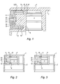
- the push button comprises a body 1 having an annular skirt of appearance 2 surrounding a well 3 mounting the push button on a tube for supplying the pressurized liquid. Furthermore, the push button comprises an upper zone 4 allowing the user to exert a digital support on said push button in order to move it axially.
- the dispensing system comprises a sampling device equipped with a tube for supplying the pressurized liquid (not shown) which is sealed in the well 3.
- the dispensing system also comprises mounting means on a bottle containing the liquid and liquid collection means inside said bottle which are arranged to supply the feed tube with liquid under pressure.
- the sampling device may comprise a manually operated pump or, in the case where the liquid is packaged under pressure in the bottle, a manually operated valve.
- a manually operated pump or, in the case where the liquid is packaged under pressure in the bottle, a manually operated valve.
- the pump or the valve is actuated to supply the supply tube with liquid under pressure.
- the body 1 also has an annular housing 5 of axis perpendicular to that of the mounting well 3, said housing having a rear wall 6 on which axially extends a cylindrical anvil 7 of revolution. Furthermore, the housing 5 is in communication with the well 3 through an orifice 8 formed in the rear wall 6 to allow the passage of the fluid supplied by the tube from said well into said housing.
- the push button also comprises a spray nozzle 9 which is associated with the body 1 by being mounted around the anvil 7 so as to form a fluid distribution path.
- the nozzle 9 is arranged collinearly with the axis of the housing 5 to allow lateral spraying of the liquid relative to the body 1 of the push button.
- the nozzle 9 has a cylindrical side wall 10 of revolution which is closed forward by a proximal wall 11.
- the association of the nozzle 9 in the housing 5 is formed by fitting the outer face of the side wall 10, the rear edge of said outer face being further provided with a radial projection 12 for anchoring the nozzle 9 in said housing.
- the nozzle 9 and the body 1 are made by molding, in particular of a different thermoplastic material.
- the material forming the nozzle 9 has a stiffness that is greater than the stiffness of the material forming the body 1.
- the significant stiffness of the nozzle 9 prevents its deformation during fitting.
- the lower stiffness of the body 1 allows on the one hand a more qualitative touch during the actuation and on the other hand an improved seal between the mounting well 3 and the feed tube.
- the greater rigidity of the nozzle 9 improves the reliability of the harpooning of the projection 12 in the housing 5 to avoid the risk of expulsion of the nozzle 9 during distribution.
- the body 1 is made of polyolefin and the nozzle 9 is made of cycloolefinic copolymer (COC), poly (oxymethylene) or poly (butylene terephthalate).
- the distribution path comprises an annular duct 13 which is formed between the inner face of the side wall 10 of the nozzle 9 and the outer face of the side wall 14 of the anvil 7.
- this annular duct 13 is supplied with pressurized liquid from port 8 by via an upstream annular duct 15 which is formed between the side wall 14 and the housing 5.
- the annular duct 13 supplies pressurized liquid to a vortex assembly comprising a vortex chamber 16 provided at its center with a dispensing orifice 17 and at least one supply channel 18 of said chamber.
- a vortex assembly comprising a vortex chamber 16 provided at its center with a dispensing orifice 17 and at least one supply channel 18 of said chamber.
- an impression of the vortex assembly is formed recess on the rear face of the proximal wall 11 of the nozzle 9 and the anvil 7 has a distal wall 19 on which the proximal wall 11 is supported to delimit between they said swirling assembly.
- the vortex assembly comprises four radial feed channels 18 which open laterally into the vortex chamber 16, said channels having a constant U-section.
- a different number of feed channels 18 may be provided. provided, possibly with an orientation and / or a modified geometry, and another mode of supply of the vortex chamber 16.
- the distal wall 19 has a recess 20 which is formed facing the cavity of the vortex chamber 16, the maximum depth of said recess being between 25% and 300% of the minimum depth of the channel 18 footprint .
- the depth of the supply channels 18 is constant and similar to that of the vortex chamber 16.
- the depth of the recess 20 is sufficient to ensure that, after pressing the nozzle 9 on the anvil 7, the geometry of the distal wall 19 which is arranged facing the vortex chamber 16 is never convex, and this taking into account the manufacturing and assembly dispersions of the nozzle 9 around the anvil 7.
- the depth of the recess 20 is sufficiently limited not to interact significantly on the characteristics of the aerosol dispensed, in particular by not being large enough to form swirling counter-chamber.
- the quality of the aerosol remains identical from one manufacture to another while maintaining high manufacturing and assembly rates.
- the maximum depth of the recess 20 is between 50% and 150% of the minimum depth of the channel footprint 18.
- the recess 20 may have an opening whose size is between 80% and 110% of the diameter of the vortex chamber 16, in particular being substantially equal to said diameter.
- the recess 20 has a geometry of revolution, more precisely cylindrical of revolution on the Figures 1 and 2 .
- a slightly frustoconical or semi-elliptical geometry can be provided as shown in FIG. figure 3 .
- the diameter of the vortex chamber 16 is 0.6 mm
- the feed channels 18 have a depth of 0.33 mm for a width of 0.2 mm
- the diameter of the recess 20 is between 0.5 and 0.6 mm for a depth before pressing between 0.1 and 0.5 mm.
Abstract
Description
L'invention concerne un bouton poussoir pour un système de distribution d'un liquide sous pression, ainsi qu'un tel système de distribution.The invention relates to a push button for a dispensing system for a pressurized liquid, as well as to such a dispensing system.
Dans une application particulière, le système de distribution est destiné à équiper des flacons utilisés en parfumerie, en cosmétique ou pour des traitements pharmaceutiques. En effet, ce type de flacon contient un liquide qui est restitué par un système de distribution comprenant un dispositif de prélèvement sous pression dudit liquide, ledit système étant actionné par un bouton poussoir pour permettre la pulvérisation du liquide. En particulier, le dispositif de prélèvement comprend une pompe ou une valve à actionnement manuel par l'intermédiaire du bouton poussoir.In a particular application, the dispensing system is intended to equip bottles used in perfumery, in cosmetics or for pharmaceutical treatments. Indeed, this type of bottle contains a liquid which is returned by a dispensing system comprising a device for sampling under pressure of said liquid, said system being actuated by a push button to allow the spraying of the liquid. In particular, the sampling device comprises a pump or a manually operated valve via the push button.
De tels boutons poussoirs sont classiquement réalisés en deux parties : un corps d'actionnement et une buse de pulvérisation du liquide qui sont associés entre eux pour former un ensemble tourbillonnaire comprenant une chambre tourbillonnaire pourvue d'un orifice de distribution ainsi que des canaux d'alimentation de ladite chambre. En particulier, la chambre tourbillonnaire est agencée pour faire tourner très rapidement le liquide afin qu'il s'échappe par l'orifice avec une vitesse suffisante pour se fractionner en gouttelettes formant l'aérosol.Such push buttons are conventionally made in two parts: an actuating body and a liquid spray nozzle which are associated with one another to form a vortex assembly comprising a vortex chamber provided with a dispensing orifice as well as channels for dispensing fluid. feeding of said chamber. In particular, the vortex chamber is arranged to rotate very quickly the liquid so that it escapes through the orifice with a sufficient speed to split into droplets forming the aerosol.
Selon une réalisation connue, la buse est montée autour d'une enclume formée dans un logement du corps. L'ensemble tourbillonnaire est alors délimité entre une paroi proximale de la buse dans laquelle est formée une empreinte dudit ensemble tourbillonnaire et une paroi distale de ladite enclume qui est classiquement plane. Pour ce faire, la buse est pressée sur l'enclume jusqu'à ce que la paroi distale soit plaquée sur la paroi proximale et ferme latéralement l'empreinte afin de former l'ensemble tourbillonnaire.According to a known embodiment, the nozzle is mounted around an anvil formed in a housing of the body. The vortex assembly is then delimited between a proximal wall of the nozzle in which is formed a cavity of said vortex assembly and a distal wall of said anvil which is classically flat. To do this, the nozzle is pressed on the anvil until the distal wall is pressed against the proximal wall and laterally closes the impression to form the swirl assembly.
On connaît par ailleurs, la réalisation d'évidements de grande profondeur dans la paroi distale de l'enclume. En particulier, le document
L'ensemble tourbillonnaire est réalisé à l'interface entre la buse et l'enclume qui, notamment compte tenu de leur taille, sont des pièces difficilement réalisables industriellement en grande quantité en maitrisant parfaitement la précision de leur géométrie. En outre, l'assemblage de la buse sur l'enclume doit être réalisé industriellement à cadence élevée, ce qui ne permet pas de garantir un positionnement optimal de ladite buse sur ladite enclume.The vortex assembly is made at the interface between the nozzle and the anvil which, particularly in view of their size, are difficult to produce industrially large quantities by perfectly mastering the accuracy of their geometry. In addition, the assembly of the nozzle on the anvil must be performed industrially at high rate, which does not ensure optimal positioning of said nozzle on said anvil.
Il en résulte donc une dispersion dans la géométrie des ensembles tourbillonnaires, ce qui affecte directement la qualité de l'aérosol distribué. En particulier, le pressage de la buse contre l'enclume entraine parfois un fluage du matériau de ladite enclume dans les canaux d'alimentation les occultant en partie.This results in a dispersion in the geometry of vortex sets, which directly affects the quality of the aerosol dispensed. In particular, the pressing of the nozzle against the anvil sometimes causes a creep material of said anvil in the supply channels partially obscuring them.
En outre, la paroi distale peut présenter après pressage une forme convexe perturbant le tourbillonnement du liquide dans la chambre. Par ailleurs, l'enclume peut subir des déformations dues au retrait du matériau lors de son refroidissement après moulage produisant sa mise en travers. La paroi distale est alors de travers ce qui entraine lors du pressage l'occultation partielle dissymétrique de certains canaux d'alimentation et surtout une paroi distale non seulement convexe, mais ne présentant pas une symétrie de révolution. L'aérosol produit est alors dit « creux », c'est à dire qu'il y a très peu de gouttelettes en son centre, ou bien déformé ce qui signifie que son impact n'est pas circulaire, ou bien désaxé, ou encore de travers par rapport à l'axe de l'orifice de distribution.In addition, the distal wall may have after pressing a convex shape disturbing the swirling of the liquid in the chamber. Furthermore, the anvil may undergo deformations due to the withdrawal of the material during its cooling after molding producing its skew. The distal wall is then crooked which causes during pressing the partial concealment of some asymmetrical supply channels and especially a distal wall not only convex, but not having a symmetry of revolution. The aerosol produced is then called "hollow", that is to say that there are very few droplets at its center, or deformed which means that its impact is not circular, or off-axis, or crosswise to the axis of the dispensing orifice.
L'invention a pour but de résoudre les problèmes de l'art antérieur en proposant notamment un bouton poussoir dans lequel la qualité de l'aérosol généré par l'ensemble tourbillonnaire peut être garantie indépendamment des dispersions de fabrication et/ou d'assemblage de la buse de pulvérisation autour de l'enclume du corps d'actionnement.The object of the invention is to solve the problems of the prior art by proposing in particular a push button in which the quality of the aerosol generated by the swirl assembly can be guaranteed independently of the dispersions of manufacture and / or assembly of the spray nozzle around the anvil of the actuating body.
A cet effet, et selon un premier aspect, l'invention propose un bouton poussoir pour un système de distribution d'un liquide sous pression, ledit bouton poussoir comprenant un corps présentant un puits de montage sur un tube d'amenée du liquide sous pression et un logement en communication avec ledit puits, ledit logement étant pourvu d'une enclume autour de laquelle une buse de pulvérisation est montée de sorte à former un chemin de distribution du fluide entre ledit logement et un ensemble tourbillonnaire comprenant une chambre tourbillonnaire pourvue d'un orifice de distribution ainsi qu'au moins un canal d'alimentation de ladite chambre, ladite buse présentant une paroi proximale dans laquelle est formée une empreinte de l'ensemble tourbillonnaire et ladite enclume présentant une paroi distale sur laquelle la paroi proximale de la buse est en appui pour délimiter entre elles ledit ensemble tourbillonnaire, ladite paroi distale présentant un évidement qui est formé en regard de l'empreinte de la chambre tourbillonnaire, la profondeur maximale dudit évidement étant comprise entre 25% et 300% de la profondeur minimale de l'empreinte des canaux d'alimentation.For this purpose, and according to a first aspect, the invention proposes a push button for a system for dispensing a liquid under pressure, said push button comprising a body having a mounting well on a tube for supplying the pressurized liquid. and a housing in communication with said well, said housing being provided with an anvil around which a spray nozzle is mounted to form a fluid distribution path between said housing and a vortex assembly comprising a vortex chamber provided with a dispensing orifice and at least one supply channel of said chamber, said nozzle having a proximal wall in which is formed an impression of the swirl assembly and said anvil having a distal wall on which the proximal wall of the nozzle is in support to delimit between them said swirl assembly, said distal wall having a recess which is formed in view of the cavity of the vortex chamber, the maximum depth of said recess being between 25% and 300% of the minimum depth of the channel footprint.
Selon un deuxième aspect, l'invention propose un système de distribution d'un liquide sous pression, comprenant un dispositif de prélèvement équipé d'un tube d'amenée du liquide sous pression sur lequel le puits d'un tel bouton poussoir est monté pour permettre la pulvérisation du liquide.According to a second aspect, the invention proposes a system for dispensing a liquid under pressure, comprising a sampling device equipped with a pressurized liquid supply tube on which the well of such a push button is mounted to allow spraying of the liquid.
D'autres objets et avantages de l'invention apparaîtront dans la description qui suit, faite en référence aux figures annexées dans lesquelles :
- la
figure 1 est une vue en coupe longitudinale partielle d'un bouton poussoir selon un mode de réalisation de l'invention ; - la
figure 2 est une vue en coupe longitudinale du corps d'actionnement du bouton poussoir selon lafigure 1 ; - la
figure 3 est une vue en coupe longitudinale d'une variante du corps d'actionnement selon lafigure 2 .
- the
figure 1 is a partial longitudinal sectional view of a push button according to one embodiment of the invention; - the
figure 2 is a longitudinal sectional view of the actuating body of the push button according to thefigure 1 ; - the
figure 3 is a longitudinal sectional view of a variant of the actuating body according to thefigure 2 .
En relation avec les figures, on décrit ci-dessous un bouton poussoir pour un système de distribution d'un liquide sous pression, ledit liquide pouvant être de toute nature, notamment utilisé en parfumerie, en cosmétique ou pour des traitements pharmaceutiques.In relation to the figures, a push button for a dispensing system for a pressurized liquid is described below, said liquid being of any nature, in particular used in perfumery, in cosmetics or for pharmaceutical treatments.
Le bouton poussoir comprend un corps 1 présentant une jupe annulaire d'aspect 2 qui entoure un puits 3 de montage du bouton poussoir sur un tube d'amenée du liquide sous pression. Par ailleurs, le bouton poussoir comprend une zone supérieure 4 permettant à l'utilisateur d'exercer un appui digital sur ledit bouton poussoir afin de pouvoir le déplacer axialement.The push button comprises a body 1 having an annular skirt of
En particulier, le système de distribution comprend un dispositif de prélèvement équipé d'un tube d'amenée du liquide sous pression (non représenté) qui est inséré de façon étanche dans le puits 3. De façon connue, le système de distribution comprend par ailleurs des moyens de montage sur un flacon contenant le liquide et des moyens de prélèvement du liquide à l'intérieur dudit flacon qui sont agencés pour alimenter le tube d'amenée en liquide sous pression.In particular, the dispensing system comprises a sampling device equipped with a tube for supplying the pressurized liquid (not shown) which is sealed in the
Le dispositif de prélèvement peut comprendre une pompe à actionnement manuel ou, dans le cas où le liquide est conditionné sous pression dans le flacon, une valve à actionnement manuel. Ainsi, lors d'un déplacement manuel du bouton poussoir, la pompe ou la valve est actionnée pour alimenter le tube d'amenée en liquide sous pression.The sampling device may comprise a manually operated pump or, in the case where the liquid is packaged under pressure in the bottle, a manually operated valve. Thus, during a manual movement of the push button, the pump or the valve is actuated to supply the supply tube with liquid under pressure.
Le corps 1 présente également un logement annulaire 5 d'axe perpendiculaire à celui du puits de montage 3, ledit logement présentant une paroi arrière 6 sur laquelle s'étend axialement une enclume 7 cylindrique de révolution. Par ailleurs, le logement 5 est en communication avec le puits 3 par l'intermédiaire d'un orifice 8 formé dans la paroi arrière 6 afin de permettre le passage du fluide amené par le tube depuis ledit puits dans ledit logement.The body 1 also has an
Le bouton poussoir comprend également une buse de pulvérisation 9 qui est associée au corps 1 en étant montée autour de l'enclume 7 de sorte à former un chemin de distribution du fluide. Dans le mode de réalisation représenté, la buse 9 est disposée colinéairement à l'axe du logement 5 pour permettre une pulvérisation latérale du liquide relativement au corps 1 du bouton poussoir.The push button also comprises a spray nozzle 9 which is associated with the body 1 by being mounted around the
Dans le mode de réalisation représenté, la buse 9 présente une paroi latérale 10 cylindrique de révolution qui est fermée vers l'avant par une paroi proximale 11. L'association de la buse 9 dans le logement 5 est réalisée par emmanchement de la face externe de la paroi latérale 10, le bord arrière de ladite face externe étant en outre pourvu d'une saillie radiale 12 d'ancrage de la buse 9 dans ledit logement.In the embodiment shown, the nozzle 9 has a cylindrical side wall 10 of revolution which is closed forward by a
De façon avantageuse, la buse 9 et le corps 1 sont réalisés par moulage, notamment d'un matériau thermoplastique différent. En outre, le matériau formant la buse 9 présente une rigidité qui est supérieure à la rigidité du matériau formant le corps 1. Ainsi, la raideur importante de la buse 9 permet d'éviter sa déformation lors de l'emmanchement. En outre, la raideur moins importante du corps 1 permet d'une part un toucher plus qualitatif lors de l'actionnement et d'autre part une étanchéité améliorée entre le puits 3 de montage et le tube d'amenée. Enfin, la rigidité plus grande de la buse 9 permet d'améliorer la fiabilité de l'harponnage de la saillie 12 dans le logement 5 afin d'éviter le risque d'expulsion de la buse 9 lors de la distribution.Advantageously, the nozzle 9 and the body 1 are made by molding, in particular of a different thermoplastic material. In addition, the material forming the nozzle 9 has a stiffness that is greater than the stiffness of the material forming the body 1. Thus, the significant stiffness of the nozzle 9 prevents its deformation during fitting. In addition, the lower stiffness of the body 1 allows on the one hand a more qualitative touch during the actuation and on the other hand an improved seal between the mounting well 3 and the feed tube. Finally, the greater rigidity of the nozzle 9 improves the reliability of the harpooning of the
Dans un exemple de réalisation, le corps 1 est réalisé en polyoléfine et la buse 9 est réalisée en copolymère cyclo oléfinique (COC), en poly(oxyméthylène) ou en poly(butylène téréphtalate).In an exemplary embodiment, the body 1 is made of polyolefin and the nozzle 9 is made of cycloolefinic copolymer (COC), poly (oxymethylene) or poly (butylene terephthalate).
Le chemin de distribution comprend un conduit annulaire 13 qui est formé entre la face interne de la paroi latérale 10 de la buse 9 et la face externe de la paroi latérale 14 de l'enclume 7. Dans le mode de réalisation représenté, ce conduit annulaire 13 est alimenté en liquide sous pression provenant de l'orifice 8 par l'intermédiaire d'un conduit annulaire amont 15 qui est formé entre la paroi latérale 14 et le logement 5.The distribution path comprises an
Du coté aval, le conduit annulaire 13 alimente en liquide sous pression un ensemble tourbillonnaire comprenant une chambre tourbillonnaire 16 pourvue en son centre d'un orifice 17 de distribution ainsi qu'au moins un canal 18 d'alimentation de ladite chambre. Pour ce faire, une empreinte de l'ensemble tourbillonnaire est formée en creux sur la face arrière de la paroi proximale 11 de la buse 9 et l'enclume 7 présente une paroi distale 19 sur laquelle la paroi proximale 11 est en appui pour délimiter entre elles ledit ensemble tourbillonnaire.On the downstream side, the
Dans le mode de réalisation représenté, l'ensemble tourbillonnaire comprend quatre canaux radiaux 18 d'alimentation qui débouchent latéralement dans la chambre tourbillonnaire 16, lesdits canaux présentant une section constante en U. Toutefois, un nombre différent de canaux 18 d'alimentation peut être prévu, avec éventuellement une orientation et/ou une géométrie modifiée, ainsi qu'un autre mode d'alimentation de la chambre tourbillonnaire 16.In the embodiment shown, the vortex assembly comprises four radial feed channels 18 which open laterally into the
La paroi distale 19 présente un évidement 20 qui est formé en regard de l'empreinte de la chambre tourbillonnaire 16, la profondeur maximale dudit évidement étant comprise entre 25% et 300% de la profondeur minimale de l'empreinte des canaux 18 d'alimentation. Dans le mode de réalisation représenté, la profondeur des canaux 18 d'alimentation est constante et analogue à celle de la chambre tourbillonnaire 16.The
Suivant l'invention, la profondeur de l'évidement 20 est suffisante pour garantir que, après pressage de la buse 9 sur l'enclume 7, la géométrie de la paroi distale 19 qui est disposée en regard de la chambre tourbillonnaire 16 ne soit jamais convexe, et ce en tenant compte des dispersions de fabrication et d'assemblage de la buse 9 autour de l'enclume 7. En outre, la profondeur de l'évidement 20 est suffisamment limitée pour ne pas interagir de façon notable sur les caractéristiques de l'aérosol distribué, notamment en n'étant pas suffisamment grand pour former contre-chambre tourbillonnaire. Ainsi, la qualité de l'aérosol reste identique d'une fabrication à l'autre tout en conservant des cadences de fabrication et d'assemblage élevées.According to the invention, the depth of the
De façon préférentielle, ces effets sont obtenus lorsque la profondeur maximale de l'évidement 20 est comprise entre 50% et 150% de la profondeur minimale de l'empreinte des canaux 18 d'alimentation. En outre, l'évidement 20 peut présenter une ouverture dont la dimension est comprise entre 80% et 110% du diamètre de la chambre tourbillonnaire 16, notamment en étant sensiblement égal audit diamètre.Preferably, these effects are obtained when the maximum depth of the
Dans le mode de réalisation représenté, l'évidement 20 présente une géométrie de révolution, plus précisément cylindrique de révolution sur les
Dans un exemple de réalisation, le diamètre de la chambre tourbillonnaire 16 est de 0,6 mm, les canaux 18 d'alimentation ont une profondeur de 0,33 mm pour une largeur de 0,2 mm, le diamètre de l'évidement 20 est compris entre 0,5 et 0,6 mm pour une profondeur comprise avant pressage entre 0,1 et 0,5 mm. Après pressage de la buse 9 sur l'enclume 7, la paroi distale 19 reste concave ou plate mais n'est jamais convexe.In an exemplary embodiment, the diameter of the
Claims (10)
Applications Claiming Priority (1)
| Application Number | Priority Date | Filing Date | Title |
|---|---|---|---|
| FR0902713A FR2946326B1 (en) | 2009-06-04 | 2009-06-04 | PUSH BUTTON FOR A PRESSURIZED LIQUID DISTRIBUTION SYSTEM |
Publications (2)
| Publication Number | Publication Date |
|---|---|
| EP2258484A1 true EP2258484A1 (en) | 2010-12-08 |
| EP2258484B1 EP2258484B1 (en) | 2014-11-05 |
Family
ID=41254672
Family Applications (1)
| Application Number | Title | Priority Date | Filing Date |
|---|---|---|---|
| EP20100290285 Active EP2258484B1 (en) | 2009-06-04 | 2010-06-01 | Push-button for a pressurised liquid distribution system |
Country Status (6)
| Country | Link |
|---|---|
| US (1) | US8640977B2 (en) |
| EP (1) | EP2258484B1 (en) |
| CN (1) | CN101905203B (en) |
| BR (1) | BRPI1001643B1 (en) |
| ES (1) | ES2529493T3 (en) |
| FR (1) | FR2946326B1 (en) |
Families Citing this family (6)
| Publication number | Priority date | Publication date | Assignee | Title |
|---|---|---|---|---|
| US9821126B2 (en) * | 2014-02-21 | 2017-11-21 | Neogen Corporation | Fluid atomizer, nozzle assembly and methods for assembling and utilizing the same |
| FR3019475B1 (en) * | 2014-04-08 | 2021-10-15 | Albea Le Treport | DISTRIBUTION MODULE OF A PRODUCT INTENDED TO BE MOUNTED ON A DUCT SUPPLIED UNDER PRESSURE OF THE SAID PRODUCT |
| US10370177B2 (en) * | 2016-11-22 | 2019-08-06 | Summit Packaging Systems, Inc. | Dual component insert with uniform discharge orifice for fine mist spray |
| WO2019191600A1 (en) * | 2018-03-30 | 2019-10-03 | Rea.Deeming Beauty, Inc. Dba Beautyblender | Container and dispenser system and apparatus |
| US10940493B2 (en) * | 2018-07-26 | 2021-03-09 | S. C. Johnson & Son, Inc. | Actuator and nozzle insert for dispensing systems |
| CN109693884A (en) * | 2019-01-29 | 2019-04-30 | 中山市美捷时包装制品有限公司 | A kind of annular aerosol actuator |
Citations (8)
| Publication number | Priority date | Publication date | Assignee | Title |
|---|---|---|---|---|
| DE19622124A1 (en) * | 1996-06-01 | 1997-12-04 | Alfred Von Schuckmann | Device for applying liquids |
| US5738282A (en) * | 1996-03-20 | 1998-04-14 | Calmar Inc. | Pump sprayer nozzle for producing a solid spray pattern |
| EP1042072A1 (en) | 1997-12-24 | 2000-10-11 | Verbena Corporation N.V. | Spray nozzle with static means for inhibiting outflow |
| WO2003018208A1 (en) * | 2001-08-23 | 2003-03-06 | Valois S.A.S. | Dispensing head for a fluid product dispenser |
| FR2832079A1 (en) | 2001-11-14 | 2003-05-16 | Valois Sa | DISPENSING HEAD AND FLUID PRODUCT DISPENSER COMPRISING SUCH A DISPENSING HEAD |
| FR2887232A1 (en) | 2005-06-21 | 2006-12-22 | Rexam Dispensing Systems Sas | Push-button nozzle for e.g. nasal sprayer, has needle valve closing spraying orifice, and barrel comprising lower end with ring connected to ejection tube and delimiting return chamber closed by snap ring carried by base of valve |
| FR2907106A1 (en) | 2006-10-16 | 2008-04-18 | Rexam Dispensing Systems Sas | Fluid product e.g. cosmetic product, dispensing device, has push-button including annular fitting wall having specific thickness with respect to recess, where thickness is specific times lower than that of thickness of wall |
| EP1925553A1 (en) * | 2006-11-22 | 2008-05-28 | Rexam Dispensing Systems | Spraying push button including an invisible nozzle |
Family Cites Families (3)
| Publication number | Priority date | Publication date | Assignee | Title |
|---|---|---|---|---|
| US2503481A (en) * | 1946-12-04 | 1950-04-11 | William W Hallinan | Atomizing nozzle |
| US3785571A (en) * | 1972-05-05 | 1974-01-15 | Seaquist Valve Co | Mechanical breakup aerosol sprayer button |
| US5992765A (en) * | 1998-04-24 | 1999-11-30 | Summit Packaging Systems, Inc. | Mechanical break-up for spray actuator |
-
2009
- 2009-06-04 FR FR0902713A patent/FR2946326B1/en active Active
-
2010
- 2010-05-27 US US12/789,071 patent/US8640977B2/en active Active
- 2010-06-01 ES ES10290285.5T patent/ES2529493T3/en active Active
- 2010-06-01 EP EP20100290285 patent/EP2258484B1/en active Active
- 2010-06-02 BR BRPI1001643-0A patent/BRPI1001643B1/en active IP Right Grant
- 2010-06-03 CN CN201010196496.6A patent/CN101905203B/en active Active
Patent Citations (9)
| Publication number | Priority date | Publication date | Assignee | Title |
|---|---|---|---|---|
| US5738282A (en) * | 1996-03-20 | 1998-04-14 | Calmar Inc. | Pump sprayer nozzle for producing a solid spray pattern |
| DE19622124A1 (en) * | 1996-06-01 | 1997-12-04 | Alfred Von Schuckmann | Device for applying liquids |
| EP1042072A1 (en) | 1997-12-24 | 2000-10-11 | Verbena Corporation N.V. | Spray nozzle with static means for inhibiting outflow |
| EP1042072B1 (en) * | 1997-12-24 | 2004-06-30 | Verbena Corporation N.V. | Spray nozzle with static means for inhibiting outflow |
| WO2003018208A1 (en) * | 2001-08-23 | 2003-03-06 | Valois S.A.S. | Dispensing head for a fluid product dispenser |
| FR2832079A1 (en) | 2001-11-14 | 2003-05-16 | Valois Sa | DISPENSING HEAD AND FLUID PRODUCT DISPENSER COMPRISING SUCH A DISPENSING HEAD |
| FR2887232A1 (en) | 2005-06-21 | 2006-12-22 | Rexam Dispensing Systems Sas | Push-button nozzle for e.g. nasal sprayer, has needle valve closing spraying orifice, and barrel comprising lower end with ring connected to ejection tube and delimiting return chamber closed by snap ring carried by base of valve |
| FR2907106A1 (en) | 2006-10-16 | 2008-04-18 | Rexam Dispensing Systems Sas | Fluid product e.g. cosmetic product, dispensing device, has push-button including annular fitting wall having specific thickness with respect to recess, where thickness is specific times lower than that of thickness of wall |
| EP1925553A1 (en) * | 2006-11-22 | 2008-05-28 | Rexam Dispensing Systems | Spraying push button including an invisible nozzle |
Also Published As
| Publication number | Publication date |
|---|---|
| US8640977B2 (en) | 2014-02-04 |
| BRPI1001643B1 (en) | 2019-10-08 |
| CN101905203A (en) | 2010-12-08 |
| CN101905203B (en) | 2014-09-24 |
| FR2946326B1 (en) | 2011-08-05 |
| EP2258484B1 (en) | 2014-11-05 |
| US20100308136A1 (en) | 2010-12-09 |
| BRPI1001643A2 (en) | 2011-08-02 |
| ES2529493T3 (en) | 2015-02-20 |
| FR2946326A1 (en) | 2010-12-10 |
Similar Documents
| Publication | Publication Date | Title |
|---|---|---|
| EP2258484B1 (en) | Push-button for a pressurised liquid distribution system | |
| EP2496361B2 (en) | Pushbutton for a system for dispensing a pressurized substance | |
| EP1935503B1 (en) | Compact pump with capacity for rotating the nozzle in relation to the piston | |
| EP2006025B1 (en) | Spray nozzle comprising balanced axial intake grooves for the whirl chamber | |
| FR2985201A1 (en) | HOLLOW DISTRIBUTION HEAD | |
| FR2985202A1 (en) | HEAD OF DISTRIBUTION | |
| FR2980125A1 (en) | Distribution head for use with e.g. pressurized container of conditioning and distribution device to spray lacquer, has restriction unit placed near junction between axial pipe and supply pipe to reduce passage section of axial pipe | |
| EP1974830B1 (en) | Distribution nozzle comprising an axially attached sealing sleeve | |
| EP3231516A1 (en) | Spray nozzle, in particular for a system for dispensing a pressurized fluid provided with a pushbutton, and dispensing system comprising such a nozzle | |
| EP2606980B1 (en) | Push button for a system for pressurised product distribution | |
| EP2119508B1 (en) | Push button for convergent distribution channels | |
| EP2295150B1 (en) | Push button for a dispensing system with pressurised product | |
| EP3206968B1 (en) | Device for dispensing a cosmetic product in aerosol form, associated assembly and method | |
| EP2446970B1 (en) | Dispensing system and dispenser for a fluid product dispenser | |
| EP2353726B1 (en) | Push button for a system for pressurised product distribution | |
| FR2927551A1 (en) | Fluid product e.g. perfume, spraying nozzle for dispenser, has supply conduit defined by internal and external edges in plane perpendicular to rotational axis, where external edge is not tangential to lateral surface of outlet channel | |
| EP2279795B1 (en) | System for dispensing a fluid product | |
| EP2233211A1 (en) | Push button for a pressurised liquid distribution system | |
| FR2972944A1 (en) | Cosmetic product i.e. hairspray dispensing device for conditioning hair, has lever arm moving sealing element between open position for permitting dispensing of cosmetic product by dispensing orifice, and closed position for sealing orifice | |
| FR2736039A1 (en) | VALVE FOR SPRAYER AND SPRAYER SO EQUIPPED | |
| FR3032895B1 (en) | PUSH BUTTON FOR A PRESSURE DISTRIBUTION SYSTEM OF A PRODUCT | |
| FR3034293A1 (en) | REMOVABLE HULL FOR PORTABLE RECHARGEABLE SPRAY | |
| EP1590097A1 (en) | Fluid product dispensing element and dispenser comprising one such element | |
| FR2855159A1 (en) | Fluid distribution head for use in e.g. cosmetic application, has body defining outlet channel with outlet end that defines distribution orifice, and insert connecting distribution unit to outlet channel | |
| EP1925553A1 (en) | Spraying push button including an invisible nozzle |
Legal Events
| Date | Code | Title | Description |
|---|---|---|---|
| PUAI | Public reference made under article 153(3) epc to a published international application that has entered the european phase |
Free format text: ORIGINAL CODE: 0009012 |
|
| AK | Designated contracting states |
Kind code of ref document: A1 Designated state(s): AL AT BE BG CH CY CZ DE DK EE ES FI FR GB GR HR HU IE IS IT LI LT LU LV MC MK MT NL NO PL PT RO SE SI SK SM TR |
|
| AX | Request for extension of the european patent |
Extension state: BA ME RS |
|
| 17P | Request for examination filed |
Effective date: 20110606 |
|
| 17Q | First examination report despatched |
Effective date: 20120814 |
|
| RAP1 | Party data changed (applicant data changed or rights of an application transferred) |
Owner name: ALBEA LE TREPORT |
|
| GRAP | Despatch of communication of intention to grant a patent |
Free format text: ORIGINAL CODE: EPIDOSNIGR1 |
|
| TPAC | Observations filed by third parties |
Free format text: ORIGINAL CODE: EPIDOSNTIPA |
|
| INTG | Intention to grant announced |
Effective date: 20140707 |
|
| GRAS | Grant fee paid |
Free format text: ORIGINAL CODE: EPIDOSNIGR3 |
|
| GRAA | (expected) grant |
Free format text: ORIGINAL CODE: 0009210 |
|
| AK | Designated contracting states |
Kind code of ref document: B1 Designated state(s): AL AT BE BG CH CY CZ DE DK EE ES FI FR GB GR HR HU IE IS IT LI LT LU LV MC MK MT NL NO PL PT RO SE SI SK SM TR |
|
| REG | Reference to a national code |
Ref country code: GB Ref legal event code: FG4D Free format text: NOT ENGLISH |
|
| REG | Reference to a national code |
Ref country code: CH Ref legal event code: EP |
|
| REG | Reference to a national code |
Ref country code: AT Ref legal event code: REF Ref document number: 694307 Country of ref document: AT Kind code of ref document: T Effective date: 20141115 |
|
| REG | Reference to a national code |
Ref country code: IE Ref legal event code: FG4D Free format text: LANGUAGE OF EP DOCUMENT: FRENCH |
|
| REG | Reference to a national code |
Ref country code: DE Ref legal event code: R096 Ref document number: 602010019946 Country of ref document: DE Effective date: 20141218 |
|
| REG | Reference to a national code |
Ref country code: ES Ref legal event code: FG2A Ref document number: 2529493 Country of ref document: ES Kind code of ref document: T3 Effective date: 20150220 |
|
| REG | Reference to a national code |
Ref country code: AT Ref legal event code: MK05 Ref document number: 694307 Country of ref document: AT Kind code of ref document: T Effective date: 20141105 |
|
| REG | Reference to a national code |
Ref country code: NL Ref legal event code: VDEP Effective date: 20141105 |
|
| REG | Reference to a national code |
Ref country code: LT Ref legal event code: MG4D |
|
| PG25 | Lapsed in a contracting state [announced via postgrant information from national office to epo] |
Ref country code: LT Free format text: LAPSE BECAUSE OF FAILURE TO SUBMIT A TRANSLATION OF THE DESCRIPTION OR TO PAY THE FEE WITHIN THE PRESCRIBED TIME-LIMIT Effective date: 20141105 Ref country code: NL Free format text: LAPSE BECAUSE OF FAILURE TO SUBMIT A TRANSLATION OF THE DESCRIPTION OR TO PAY THE FEE WITHIN THE PRESCRIBED TIME-LIMIT Effective date: 20141105 Ref country code: PT Free format text: LAPSE BECAUSE OF FAILURE TO SUBMIT A TRANSLATION OF THE DESCRIPTION OR TO PAY THE FEE WITHIN THE PRESCRIBED TIME-LIMIT Effective date: 20150305 Ref country code: IS Free format text: LAPSE BECAUSE OF FAILURE TO SUBMIT A TRANSLATION OF THE DESCRIPTION OR TO PAY THE FEE WITHIN THE PRESCRIBED TIME-LIMIT Effective date: 20150305 Ref country code: NO Free format text: LAPSE BECAUSE OF FAILURE TO SUBMIT A TRANSLATION OF THE DESCRIPTION OR TO PAY THE FEE WITHIN THE PRESCRIBED TIME-LIMIT Effective date: 20150205 Ref country code: FI Free format text: LAPSE BECAUSE OF FAILURE TO SUBMIT A TRANSLATION OF THE DESCRIPTION OR TO PAY THE FEE WITHIN THE PRESCRIBED TIME-LIMIT Effective date: 20141105 |
|
| PG25 | Lapsed in a contracting state [announced via postgrant information from national office to epo] |
Ref country code: SE Free format text: LAPSE BECAUSE OF FAILURE TO SUBMIT A TRANSLATION OF THE DESCRIPTION OR TO PAY THE FEE WITHIN THE PRESCRIBED TIME-LIMIT Effective date: 20141105 Ref country code: PL Free format text: LAPSE BECAUSE OF FAILURE TO SUBMIT A TRANSLATION OF THE DESCRIPTION OR TO PAY THE FEE WITHIN THE PRESCRIBED TIME-LIMIT Effective date: 20141105 Ref country code: AT Free format text: LAPSE BECAUSE OF FAILURE TO SUBMIT A TRANSLATION OF THE DESCRIPTION OR TO PAY THE FEE WITHIN THE PRESCRIBED TIME-LIMIT Effective date: 20141105 Ref country code: GR Free format text: LAPSE BECAUSE OF FAILURE TO SUBMIT A TRANSLATION OF THE DESCRIPTION OR TO PAY THE FEE WITHIN THE PRESCRIBED TIME-LIMIT Effective date: 20150206 Ref country code: LV Free format text: LAPSE BECAUSE OF FAILURE TO SUBMIT A TRANSLATION OF THE DESCRIPTION OR TO PAY THE FEE WITHIN THE PRESCRIBED TIME-LIMIT Effective date: 20141105 Ref country code: HR Free format text: LAPSE BECAUSE OF FAILURE TO SUBMIT A TRANSLATION OF THE DESCRIPTION OR TO PAY THE FEE WITHIN THE PRESCRIBED TIME-LIMIT Effective date: 20141105 Ref country code: CY Free format text: LAPSE BECAUSE OF FAILURE TO SUBMIT A TRANSLATION OF THE DESCRIPTION OR TO PAY THE FEE WITHIN THE PRESCRIBED TIME-LIMIT Effective date: 20141105 |
|
| REG | Reference to a national code |
Ref country code: FR Ref legal event code: PLFP Year of fee payment: 6 |
|
| PG25 | Lapsed in a contracting state [announced via postgrant information from national office to epo] |
Ref country code: CZ Free format text: LAPSE BECAUSE OF FAILURE TO SUBMIT A TRANSLATION OF THE DESCRIPTION OR TO PAY THE FEE WITHIN THE PRESCRIBED TIME-LIMIT Effective date: 20141105 Ref country code: EE Free format text: LAPSE BECAUSE OF FAILURE TO SUBMIT A TRANSLATION OF THE DESCRIPTION OR TO PAY THE FEE WITHIN THE PRESCRIBED TIME-LIMIT Effective date: 20141105 Ref country code: DK Free format text: LAPSE BECAUSE OF FAILURE TO SUBMIT A TRANSLATION OF THE DESCRIPTION OR TO PAY THE FEE WITHIN THE PRESCRIBED TIME-LIMIT Effective date: 20141105 Ref country code: SK Free format text: LAPSE BECAUSE OF FAILURE TO SUBMIT A TRANSLATION OF THE DESCRIPTION OR TO PAY THE FEE WITHIN THE PRESCRIBED TIME-LIMIT Effective date: 20141105 Ref country code: RO Free format text: LAPSE BECAUSE OF FAILURE TO SUBMIT A TRANSLATION OF THE DESCRIPTION OR TO PAY THE FEE WITHIN THE PRESCRIBED TIME-LIMIT Effective date: 20141105 |
|
| REG | Reference to a national code |
Ref country code: DE Ref legal event code: R097 Ref document number: 602010019946 Country of ref document: DE |
|
| PLBE | No opposition filed within time limit |
Free format text: ORIGINAL CODE: 0009261 |
|
| STAA | Information on the status of an ep patent application or granted ep patent |
Free format text: STATUS: NO OPPOSITION FILED WITHIN TIME LIMIT |
|
| 26N | No opposition filed |
Effective date: 20150806 |
|
| PG25 | Lapsed in a contracting state [announced via postgrant information from national office to epo] |
Ref country code: MC Free format text: LAPSE BECAUSE OF FAILURE TO SUBMIT A TRANSLATION OF THE DESCRIPTION OR TO PAY THE FEE WITHIN THE PRESCRIBED TIME-LIMIT Effective date: 20141105 |
|
| REG | Reference to a national code |
Ref country code: CH Ref legal event code: PL |
|
| GBPC | Gb: european patent ceased through non-payment of renewal fee |
Effective date: 20150601 |
|
| PG25 | Lapsed in a contracting state [announced via postgrant information from national office to epo] |
Ref country code: LU Free format text: LAPSE BECAUSE OF FAILURE TO SUBMIT A TRANSLATION OF THE DESCRIPTION OR TO PAY THE FEE WITHIN THE PRESCRIBED TIME-LIMIT Effective date: 20150601 Ref country code: SI Free format text: LAPSE BECAUSE OF FAILURE TO SUBMIT A TRANSLATION OF THE DESCRIPTION OR TO PAY THE FEE WITHIN THE PRESCRIBED TIME-LIMIT Effective date: 20141105 |
|
| REG | Reference to a national code |
Ref country code: IE Ref legal event code: MM4A |
|
| PG25 | Lapsed in a contracting state [announced via postgrant information from national office to epo] |
Ref country code: LI Free format text: LAPSE BECAUSE OF NON-PAYMENT OF DUE FEES Effective date: 20150630 Ref country code: CH Free format text: LAPSE BECAUSE OF NON-PAYMENT OF DUE FEES Effective date: 20150630 Ref country code: IE Free format text: LAPSE BECAUSE OF NON-PAYMENT OF DUE FEES Effective date: 20150601 Ref country code: GB Free format text: LAPSE BECAUSE OF NON-PAYMENT OF DUE FEES Effective date: 20150601 |
|
| REG | Reference to a national code |
Ref country code: FR Ref legal event code: PLFP Year of fee payment: 7 |
|
| PG25 | Lapsed in a contracting state [announced via postgrant information from national office to epo] |
Ref country code: MT Free format text: LAPSE BECAUSE OF FAILURE TO SUBMIT A TRANSLATION OF THE DESCRIPTION OR TO PAY THE FEE WITHIN THE PRESCRIBED TIME-LIMIT Effective date: 20141105 |
|
| PG25 | Lapsed in a contracting state [announced via postgrant information from national office to epo] |
Ref country code: SM Free format text: LAPSE BECAUSE OF FAILURE TO SUBMIT A TRANSLATION OF THE DESCRIPTION OR TO PAY THE FEE WITHIN THE PRESCRIBED TIME-LIMIT Effective date: 20141105 Ref country code: BG Free format text: LAPSE BECAUSE OF FAILURE TO SUBMIT A TRANSLATION OF THE DESCRIPTION OR TO PAY THE FEE WITHIN THE PRESCRIBED TIME-LIMIT Effective date: 20141105 Ref country code: HU Free format text: LAPSE BECAUSE OF FAILURE TO SUBMIT A TRANSLATION OF THE DESCRIPTION OR TO PAY THE FEE WITHIN THE PRESCRIBED TIME-LIMIT; INVALID AB INITIO Effective date: 20100601 |
|
| REG | Reference to a national code |
Ref country code: FR Ref legal event code: PLFP Year of fee payment: 8 |
|
| PG25 | Lapsed in a contracting state [announced via postgrant information from national office to epo] |
Ref country code: BE Free format text: LAPSE BECAUSE OF NON-PAYMENT OF DUE FEES Effective date: 20150630 |
|
| PG25 | Lapsed in a contracting state [announced via postgrant information from national office to epo] |
Ref country code: TR Free format text: LAPSE BECAUSE OF FAILURE TO SUBMIT A TRANSLATION OF THE DESCRIPTION OR TO PAY THE FEE WITHIN THE PRESCRIBED TIME-LIMIT Effective date: 20141105 |
|
| REG | Reference to a national code |
Ref country code: FR Ref legal event code: PLFP Year of fee payment: 9 |
|
| PG25 | Lapsed in a contracting state [announced via postgrant information from national office to epo] |
Ref country code: MK Free format text: LAPSE BECAUSE OF FAILURE TO SUBMIT A TRANSLATION OF THE DESCRIPTION OR TO PAY THE FEE WITHIN THE PRESCRIBED TIME-LIMIT Effective date: 20141105 |
|
| PG25 | Lapsed in a contracting state [announced via postgrant information from national office to epo] |
Ref country code: AL Free format text: LAPSE BECAUSE OF FAILURE TO SUBMIT A TRANSLATION OF THE DESCRIPTION OR TO PAY THE FEE WITHIN THE PRESCRIBED TIME-LIMIT Effective date: 20141105 |
|
| PGFP | Annual fee paid to national office [announced via postgrant information from national office to epo] |
Ref country code: FR Payment date: 20230626 Year of fee payment: 14 Ref country code: DE Payment date: 20230626 Year of fee payment: 14 |
|
| PGFP | Annual fee paid to national office [announced via postgrant information from national office to epo] |
Ref country code: IT Payment date: 20230620 Year of fee payment: 14 Ref country code: ES Payment date: 20230703 Year of fee payment: 14 |