EP2258456A2 - Operation device - Google Patents
Operation device Download PDFInfo
- Publication number
- EP2258456A2 EP2258456A2 EP10005587A EP10005587A EP2258456A2 EP 2258456 A2 EP2258456 A2 EP 2258456A2 EP 10005587 A EP10005587 A EP 10005587A EP 10005587 A EP10005587 A EP 10005587A EP 2258456 A2 EP2258456 A2 EP 2258456A2
- Authority
- EP
- European Patent Office
- Prior art keywords
- button
- user
- operation device
- thumb
- recessed portion
- Prior art date
- Legal status (The legal status is an assumption and is not a legal conclusion. Google has not performed a legal analysis and makes no representation as to the accuracy of the status listed.)
- Granted
Links
Images

Classifications
-
- A—HUMAN NECESSITIES
- A63—SPORTS; GAMES; AMUSEMENTS
- A63F—CARD, BOARD, OR ROULETTE GAMES; INDOOR GAMES USING SMALL MOVING PLAYING BODIES; VIDEO GAMES; GAMES NOT OTHERWISE PROVIDED FOR
- A63F13/00—Video games, i.e. games using an electronically generated display having two or more dimensions
- A63F13/20—Input arrangements for video game devices
- A63F13/21—Input arrangements for video game devices characterised by their sensors, purposes or types
- A63F13/213—Input arrangements for video game devices characterised by their sensors, purposes or types comprising photodetecting means, e.g. cameras, photodiodes or infrared cells
-
- A—HUMAN NECESSITIES
- A63—SPORTS; GAMES; AMUSEMENTS
- A63F—CARD, BOARD, OR ROULETTE GAMES; INDOOR GAMES USING SMALL MOVING PLAYING BODIES; VIDEO GAMES; GAMES NOT OTHERWISE PROVIDED FOR
- A63F13/00—Video games, i.e. games using an electronically generated display having two or more dimensions
- A63F13/20—Input arrangements for video game devices
- A63F13/21—Input arrangements for video game devices characterised by their sensors, purposes or types
- A63F13/218—Input arrangements for video game devices characterised by their sensors, purposes or types using pressure sensors, e.g. generating a signal proportional to the pressure applied by the player
-
- A—HUMAN NECESSITIES
- A63—SPORTS; GAMES; AMUSEMENTS
- A63F—CARD, BOARD, OR ROULETTE GAMES; INDOOR GAMES USING SMALL MOVING PLAYING BODIES; VIDEO GAMES; GAMES NOT OTHERWISE PROVIDED FOR
- A63F13/00—Video games, i.e. games using an electronically generated display having two or more dimensions
- A63F13/20—Input arrangements for video game devices
- A63F13/23—Input arrangements for video game devices for interfacing with the game device, e.g. specific interfaces between game controller and console
- A63F13/235—Input arrangements for video game devices for interfacing with the game device, e.g. specific interfaces between game controller and console using a wireless connection, e.g. infrared or piconet
-
- A—HUMAN NECESSITIES
- A63—SPORTS; GAMES; AMUSEMENTS
- A63F—CARD, BOARD, OR ROULETTE GAMES; INDOOR GAMES USING SMALL MOVING PLAYING BODIES; VIDEO GAMES; GAMES NOT OTHERWISE PROVIDED FOR
- A63F13/00—Video games, i.e. games using an electronically generated display having two or more dimensions
- A63F13/20—Input arrangements for video game devices
- A63F13/24—Constructional details thereof, e.g. game controllers with detachable joystick handles
-
- A—HUMAN NECESSITIES
- A63—SPORTS; GAMES; AMUSEMENTS
- A63F—CARD, BOARD, OR ROULETTE GAMES; INDOOR GAMES USING SMALL MOVING PLAYING BODIES; VIDEO GAMES; GAMES NOT OTHERWISE PROVIDED FOR
- A63F13/00—Video games, i.e. games using an electronically generated display having two or more dimensions
- A63F13/25—Output arrangements for video game devices
- A63F13/26—Output arrangements for video game devices having at least one additional display device, e.g. on the game controller or outside a game booth
-
- A—HUMAN NECESSITIES
- A63—SPORTS; GAMES; AMUSEMENTS
- A63F—CARD, BOARD, OR ROULETTE GAMES; INDOOR GAMES USING SMALL MOVING PLAYING BODIES; VIDEO GAMES; GAMES NOT OTHERWISE PROVIDED FOR
- A63F2300/00—Features of games using an electronically generated display having two or more dimensions, e.g. on a television screen, showing representations related to the game
- A63F2300/10—Features of games using an electronically generated display having two or more dimensions, e.g. on a television screen, showing representations related to the game characterized by input arrangements for converting player-generated signals into game device control signals
- A63F2300/1043—Features of games using an electronically generated display having two or more dimensions, e.g. on a television screen, showing representations related to the game characterized by input arrangements for converting player-generated signals into game device control signals being characterized by constructional details
-
- A—HUMAN NECESSITIES
- A63—SPORTS; GAMES; AMUSEMENTS
- A63F—CARD, BOARD, OR ROULETTE GAMES; INDOOR GAMES USING SMALL MOVING PLAYING BODIES; VIDEO GAMES; GAMES NOT OTHERWISE PROVIDED FOR
- A63F2300/00—Features of games using an electronically generated display having two or more dimensions, e.g. on a television screen, showing representations related to the game
- A63F2300/10—Features of games using an electronically generated display having two or more dimensions, e.g. on a television screen, showing representations related to the game characterized by input arrangements for converting player-generated signals into game device control signals
- A63F2300/1056—Features of games using an electronically generated display having two or more dimensions, e.g. on a television screen, showing representations related to the game characterized by input arrangements for converting player-generated signals into game device control signals involving pressure sensitive buttons
-
- A—HUMAN NECESSITIES
- A63—SPORTS; GAMES; AMUSEMENTS
- A63F—CARD, BOARD, OR ROULETTE GAMES; INDOOR GAMES USING SMALL MOVING PLAYING BODIES; VIDEO GAMES; GAMES NOT OTHERWISE PROVIDED FOR
- A63F2300/00—Features of games using an electronically generated display having two or more dimensions, e.g. on a television screen, showing representations related to the game
- A63F2300/10—Features of games using an electronically generated display having two or more dimensions, e.g. on a television screen, showing representations related to the game characterized by input arrangements for converting player-generated signals into game device control signals
- A63F2300/1087—Features of games using an electronically generated display having two or more dimensions, e.g. on a television screen, showing representations related to the game characterized by input arrangements for converting player-generated signals into game device control signals comprising photodetecting means, e.g. a camera
Definitions
- the present invention relates to an operation device to be held by a user in their hand when used.
- Those operation devices include an operation device to be held by a user in their hand when used, such as a controller for a video game console (see US 2007/0117625 ).
- a button for operation input is provided on a surface of such an operation device
- the button is provided at a position at which the user places their thumb or finger when the user holds the operation device with their hand, the user does not need to move their thumb or finger onto the button every time they depresses the button, which results in easier operation.
- the user holds the operation device with their thumb or finger placed on the button, there is a higher risk of erroneous operation in which the user depresses the button inadvertently.
- the present invention has been made in view of the above-mentioned circumstances, and has an object to provide an operation device including an operation button which is easy to operate and unlikely to cause erroneous operation when the user uses the operation device by holding the operation device with their hand.
- an operation device to be held by a user with one hand when used including: a recessed portion formed at a position at which at least one of a thumb and fingers is placed when the user holds the operation device; and a first button which is disposed at a bottom of the recessed portion and has a top surface adjacent to a rim portion forming a side surface of the recessed portion.
- the operation device may further include a second button disposed at a position opposite to the first button on a surface of the operation device, at which another one of the thumb and fingers of the user other than the at least one of the thumb and fingers is to be placed.
- the second button may include a button capable of detecting an amount by which the second button is depressed by the user.
- the operation device may further include another button which is disposed at a periphery of the recessed portion and used along with the first button.
- the other button which is disposed at a periphery of the recessed portion may be disposed at a position which corresponds to an end of the recessed portion in a longitudinal direction.
- FIG. 1 is a schematic diagram illustrating a use situation of an information processing system 1 including an operation device 10 according to the embodiment of the present invention.
- the information processing system 1 includes the operation device 10 to be held by a user with their hand when used, and an information processing apparatus 20.
- the information processing apparatus 20 is, for example, a video game console, a personal computer, or the like, and is connected to an image capture apparatus 21 and a display apparatus 22.
- the operation device 10 is capable of establishing communication with the information processing apparatus 20 via a wireless communication interface compliant with, for example, the Bluetooth standard.
- the user of the information processing system 1 holds the operation device 10 with their hand to operate a button or the like provided on the operation device 10.
- the operation device 10 includes a light emitting portion 12, and the light emitting portion 12 emits light according to an instruction from the information processing apparatus 20.
- the information processing apparatus 20 uses the image capture apparatus 21 to capture an image of the light emitted from the light emitting portion 12. Then, the information processing apparatus 20 analyzes the captured image to thereby identify a position of the operation device 10 which is viewed from the image capture apparatus 21.
- the user can perform operation input to the information processing apparatus 20 not only by operating a button or the like provided to the operation device 10, but also by moving the operation device 10 itself.
- FIGS. 2 to 5 are diagrams each illustrating an outer appearance of the operation device 10.
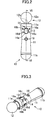
- FIG. 2 is a front view of the operation device 10.
- FIG. 3 is a perspective view of the operation device 10 when viewed from a front side thereof.
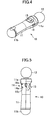
- FIG. 4 is a perspective view of the operation device 10 when viewed from a back side thereof.
- FIG. 5 is a right side view of the operation device 10.
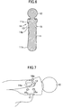
- FIG. 6 is a sectional view of the operation device 10 which is taken along a line VI-VI of FIG. 2 .
- the operation device 10 includes a main body portion 11 and the light emitting portion 12, and the main body portion 11 is provided with a plurality of buttons on a surface thereof. The user holds the main body portion 11, and performs the operation input in which the user depresses the buttons with their thumb and fingers. Those buttons are described later in detail.
- the main body portion 11 is formed in a cylindrical shape as a whole, and has the light emitting portion 12 attached at one end thereof.
- the surface of the cylindrical column forming the main body portion 11 is gently incurved toward the vicinity of the center in a longitudinal direction thereof. With this configuration, a portion in the vicinity of the center of the main body portion 11 is narrower than portions at both ends thereof.
- protruding portions 11a and 11b that protrude outward compared to the portion in the vicinity of the center of the main body portion 11 are respectively formed.
- the light emitting portion 12 includes a spherical-shaped outer shell 12a formed of a light transmissive material, such as a silicone resin, and a plurality of LEDs 12b disposed thereinside.
- a light transmissive material such as a silicone resin
- three LEDs 12b corresponding to the three primary colors of light each emit light with an intensity corresponding to an instruction from the information processing apparatus 20, thereby enabling the light emitting portion 12 to emit light with various colors.
- the image capture apparatus 21 captures an image of the light emitted from the light emitting portion 12, and accordingly, the information processing apparatus 20 identifies a direction of the operation device 10 with respect to the image capture apparatus 21.
- a distance from the image capture apparatus 21 to the operation device 10 is calculated. Based on such information regarding the direction and the distance of the operation device 10, the information processing apparatus 20 performs various kinds of information processing. With this configuration, by holding and moving the operation device 10 with their hand, the user can perform the operation input to the information processing apparatus 20.
- various kinds of detection means for detecting attitude and movement of the operation device 10 such as an acceleration sensor, a gyroscope, and a geomagnetic sensor, may be provided inside the main body portion 11.
- detection means for detecting attitude and movement of the operation device 10 such as an acceleration sensor, a gyroscope, and a geomagnetic sensor.
- the one end of the main body portion 11 to which the light emitting portion 12 is attached has a larger diameter than the outer shell 12a in a cross section perpendicular to the longitudinal direction of the main body portion 11.
- the perimeter of the protruding portion 11a appears as surrounding the perimeter of the outer shell 12a.
- the portion in the vicinity of the center of the main body portion 11 which is to be held by the user is formed to be narrower than the protruding portion 11a.
- a main button 13 an analog button 15, auxiliary buttons 16a to 16d, a start button 17, a select button 18, and a power button 19 are disposed on an enclosure surface of the main body portion 11.
- the main button 13 is disposed, on the front side of the operation device 10, at a position at which the thumb is placed when the user holds the operation device 10 with their hand. Further, the main button 13 is disposed at a bottom of a recessed portion 14 formed at the front of the main body portion 11, and a top surface of the main button 13 is adjacent to a rim portion 14a forming a side surface of the recessed portion 14. Specifically, the top surface of the main button 13 is formed so as to be continuous with the adjacent rim portion 14a, and is positioned lower than the surface of the main body portion 11 which surrounds the recessed portion 14. In this embodiment, the main button 13 corresponds to a first button.
- the main button 13 is assigned a function associated with an instruction expected to be given particularly frequently by the user. Specifically, examples of such an instruction include a confirmation instruction for confirming the contents of instructions given so far by the user.
- the recessed portion 14 has, when viewed from the front of the operation device 10, an approximately rectangular shape with four corners thereof rounded, and a longitudinal direction thereof (that is, long-side direction of a rectangle) coincides with the longitudinal direction of the operation device 10.
- the short side of the rectangle has a length which corresponds to a width of a person's thumb, thereby making it easy to place the thumb within the recessed portion 14.
- the side surface of the recessed portion 14 may be an inclined surface which inclines toward the outside of the recessed portion 14 to form a mortar shape.
- the buttons including the main button 13 are disposed, on the side surface of the main body portion 11, in a cylindrical area ranging from a top end of the recessed portion 14 (end on the side of the light emitting portion 12) to a bottom end thereof (end on the side of the bottom) .
- the user holds the narrowed portion in the vicinity of the center of the main body portion 11 by mainly using their palm, middle finger, ring finger, and little finger. Then, the user uses their thumb and index finger to operate the buttons disposed in the cylindrical area between the portion in the vicinity of the center of the main body portion 11 and the light emitting portion 12.
- the analog button 15 is disposed on the back side of the operation device 10 (that is, side opposite to the side where the main button 13 is disposed) so as to oppose the main button 13.
- the user holds the portion in the vicinity of the center of the main body portion 11 and places their thumb onto the main button 13 as described above, and also places their index finger onto the analog button 15.
- the thumb and the index finger are in a state of facing each other with the main body portion 11 sandwiched therebetween.
- the user performs the operation input by depressing the main button 13 and the analog button 15 with their thumb and index finger, respectively.
- the analog button 15 corresponds to a second button.
- the analog button 15 is capable of detecting to what extent the button is depressed by the user and outputting information indicating the depressed amount. With this configuration, the user can input quantitative information by depressing the analog button 15 lightly or heavily. Note that in order to enable such operation input that corresponds to the depressed amount, the analog button 15 has a larger movable range than the main button 13, and requires a larger stroke amount to be depressed fully than the main button 13.
- a button (analog button 15) is also provided at the position at which the index finger is to be placed.
- the analog button 15 is a device for performing the operation input which corresponds to the depressed amount as described above, the analog button 15 may not be operated constantly with light force and there is a case where the analog button 15 should be depressed with intense force. Accordingly, there is a fear that, when the user attempts to operate the analog button 15, the user may unconsciously move their thumb and mistakenly depresses the main button 13.
- the main button 13 is disposed at the bottom of the recessed portion 14 so that the top surface of the main button 13 is located adjacent to the rim portion 14a.
- the user puts their thumb across a portion in which the main button 13 is adjacent to the rim portion 14a in such a manner that the thumb rests on the rim portion 14a.
- FIG. 7 is a diagram illustrating a situation in which the user is holding the main body portion 11 as described above. If the user holds the main body portion 11 as described above, the user only needs to apply force toward the rim portion 14a with their thumb when the user depresses the analog button 15. Consequently, the user can operate the analog button 15 with an arbitrary force without mistakenly operating the main button 13. Further, because the user places their thumb on the main button 13, the user does not need to shift their thumb significantly in operating the main button 13.
- the top surface of the main button 13 and the rim portion 14a are formed in a continuous manner, but as long as the top surface of the main button 13 and the rim portion 14a are close enough to each other for the user to be able to place their thumb across the main button 13 and the rim portion 14a, there may be a gap therebetween.
- the four auxiliary buttons 16a to 16d are disposed so as to surround the main button 13. Specifically, those auxiliary buttons 16a to 16d are used for various kinds of operation input along with the main button 13 during execution of an application program such as a game application program.
- Each of the auxiliary buttons 16a to 16d is disposed at a position which corresponds to one of the ends of the recessed portion 14 formed in the rectangular shape in the longitudinal direction.
- the auxiliary buttons 16a and 16b are disposed at positions displaced rightward and leftward (that is, directions substantially perpendicular to the longitudinal direction of the recessed portion 14), respectively, from the upper end (end on the side of the light emitting portion 12) of the recessed portion 14.
- the auxiliary buttons 16c and 16d are disposed at positions displaced rightward and leftward, respectively, from the lower end (end on the side of the bottom) of the recessed portion 14.
- the user can recognize the positions of both ends of the recessed portion 14 in the longitudinal direction by touching the rim portion 14a with their thumb placed within the recessed portion 14. Accordingly, by shifting the thumb laterally from the position of one of the two ends of the recessed portion 14 to the position of an auxiliary button which the user desires to operate, it is possible for the user to move their thumb and operate the auxiliary button with ease without actually taking a look at the operation device 10 to check.
- the rim portion 14a serves to prevent the user from performing erroneous operation with respect to the main button 13 by enabling the user's thumb to be placed on the rim portion 14a along with the main button 13 as described above, and also functions as a guide portion when the user feels for the auxiliary buttons.
- the user can recognize the positions of the both ends of the recessed portion 14 by touching, of the side surfaces of the recessed portion 14, the surfaces perpendicular to the longitudinal direction of the recessed portion 14 (that is, surfaces along the short sides of the rectangle).
- the side surface of the recessed portion 14 which is formed in such a direction functions as the guide portion for the user to recognize the positions of the auxiliary buttons.
- the auxiliary buttons 16c and 16d disposed at the positions corresponding to the lower end (end closer to the portion at which the user holds the main body portion 11) of the recessed portion 14 are disposed at positions relatively closer to the recessed portion 14, compared to the auxiliary buttons 16a and 16b disposed at the positions corresponding to the end farther from the portion at which the user holds the main body portion 11.
- the user can operate the auxiliary button 16a by swinging their thumb from the main button 13 to the same extent as a case where the user operates the auxiliary button 16c.
- the start button 17 and the select button 18 are used for starting a game, selecting a game, pausing, or the like during execution, for example, of a game application program. For this reason, in general, those buttons are not used frequently during the execution of a game. Accordingly, in this embodiment, those two buttons are disposed on the right side surface and the left side surface of the main body portion 11, respectively. Specifically, the start button 17 and the select button 18 are disposed, in a cross section perpendicular to the longitudinal direction of the main body portion 11, so as to oppose each other on a line substantially perpendicular to a line connecting the main button 13 and the analog button 15.
- both the start button 17 and the select button 18 are substantially identical in height to upper ends of the main button 13 and the analog button 15.
- the upper ends of the main button 13, the analog button 15, the auxiliary buttons 16a and 16b, the start button 17, and the select button 18 are aligned on substantially the same straight line. Therefore, by rotating the main body portion 11 in the palm or moving the thumb or the index finger significantly, similarly to the case of the auxiliary buttons 16a and 16b, the user can operate the start button 17 and the select button 18 without directly taking a look at the button to check its position.
- the power button 19 is disposed, at the front of the main body portion 11, below the position at which the main button 13 is disposed.
- the power button 19 is used for powering on the operation device 10 to start operation thereof or powering off the operation device 10 to terminate the operation.
- the power button 19 is not operated during the execution of the application program or the like.
- USB universal serial bus
- a portion surrounding the USB connector is provided with a removable cover, and the inside of the portion which is exposed by removing the cover is provided with extension connectors for connecting other equipment.
- the cover is provided with a through hole through which a string such as a strap is passed.
- the main body portion 11 is incurved toward the vicinity of the center thereof, and the protruding portions 11a and 11b are formed at both ends thereof. Therefore, when the operation device 10 is laid on its side on a floor surface, the protruding portions 11a and 11b come into contact with the floor surface, and a portion therebetween is not brought into direct contact with the floor surface.
- the analog button 15, the auxiliary buttons 16a to 16d, and the like may be formed so that heights thereof do not exceed a curved surface formed by connecting the perimeters of the protruding portions 11a and 11b to each other. With this configuration, as well as the main button 13 formed inside the recessed portion 14, the other buttons are also prevented from being mistakenly depressed when the operation device 10 is laid on its side on the floor.
- the main button 13 is disposed so that the main button 13 is adjacent to the rim portion 14a which forms, inside the recessed portion 14, the side surface of the recessed portion 14. Therefore, even when the user holds the operation device 10 with their thumb placed on the main button 13, the user can be prevented from mistakenly operating the main button 13.
- the main button 13 to be operated with the thumb is disposed inside the recessed portion 14, but the present invention is not limited thereto.
- a button to be operated with another finger may be disposed inside a recessed portion formed on the enclosure surface of the operation device 10.
Landscapes
- Engineering & Computer Science (AREA)
- Multimedia (AREA)
- Human Computer Interaction (AREA)
- Computer Networks & Wireless Communication (AREA)
- Position Input By Displaying (AREA)
- Input From Keyboards Or The Like (AREA)
- Mechanical Control Devices (AREA)
- Push-Button Switches (AREA)
Abstract
Description
- The present invention relates to an operation device to be held by a user in their hand when used.
- Various kinds of operation devices that are used for operating information processing apparatuses have been proposed. Those operation devices include an operation device to be held by a user in their hand when used, such as a controller for a video game console (see
US 2007/0117625 ). - In a case where a button for operation input is provided on a surface of such an operation device, if the button is provided at a position at which the user places their thumb or finger when the user holds the operation device with their hand, the user does not need to move their thumb or finger onto the button every time they depresses the button, which results in easier operation. However, if the user holds the operation device with their thumb or finger placed on the button, there is a higher risk of erroneous operation in which the user depresses the button inadvertently.
- The present invention has been made in view of the above-mentioned circumstances, and has an object to provide an operation device including an operation button which is easy to operate and unlikely to cause erroneous operation when the user uses the operation device by holding the operation device with their hand.
- According to the present invention, there is provided an operation device to be held by a user with one hand when used, including: a recessed portion formed at a position at which at least one of a thumb and fingers is placed when the user holds the operation device; and a first button which is disposed at a bottom of the recessed portion and has a top surface adjacent to a rim portion forming a side surface of the recessed portion.
- The operation device may further include a second button disposed at a position opposite to the first button on a surface of the operation device, at which another one of the thumb and fingers of the user other than the at least one of the thumb and fingers is to be placed.
- Further, the second button may include a button capable of detecting an amount by which the second button is depressed by the user.
- Further, the operation device may further include another button which is disposed at a periphery of the recessed portion and used along with the first button.
- Further, the other button which is disposed at a periphery of the recessed portion may be disposed at a position which corresponds to an end of the recessed portion in a longitudinal direction.
- In the accompanying drawings:
-
FIG. 1 is a schematic diagram illustrating a use example of an operation device according to an embodiment of the present invention; -
FIG. 2 is a front view of the operation device according to the embodiment of the present invention; -
FIG. 3 is a perspective view of the operation device according to the embodiment of the present invention when viewed from a front side thereof; -
FIG. 4 is a perspective view of the operation device according to the embodiment of the present invention when viewed from a back side thereof; -
FIG. 5 is a right side view of the operation device according to the embodiment of the present invention; -
FIG. 6 is a sectional view of the operation device according to the embodiment of the present invention; and -
FIG. 7 is a diagram illustrating a situation in which a user is holding the operation device according to the embodiment of the present invention. - Hereinbelow, with reference to the drawings, detailed description is given of an embodiment of the present invention.
-
FIG. 1 is a schematic diagram illustrating a use situation of an information processing system 1 including anoperation device 10 according to the embodiment of the present invention. As illustrated inFIG. 1 , the information processing system 1 includes theoperation device 10 to be held by a user with their hand when used, and aninformation processing apparatus 20. Theinformation processing apparatus 20 is, for example, a video game console, a personal computer, or the like, and is connected to animage capture apparatus 21 and adisplay apparatus 22. Theoperation device 10 is capable of establishing communication with theinformation processing apparatus 20 via a wireless communication interface compliant with, for example, the Bluetooth standard. The user of the information processing system 1 holds theoperation device 10 with their hand to operate a button or the like provided on theoperation device 10. In response to such an operation, content of the operation performed by the user is transmitted to theinformation processing apparatus 20 via the wireless communication interface. Further, in this embodiment, theoperation device 10 includes alight emitting portion 12, and thelight emitting portion 12 emits light according to an instruction from theinformation processing apparatus 20. Theinformation processing apparatus 20 uses theimage capture apparatus 21 to capture an image of the light emitted from thelight emitting portion 12. Then, theinformation processing apparatus 20 analyzes the captured image to thereby identify a position of theoperation device 10 which is viewed from theimage capture apparatus 21. With this configuration, the user can perform operation input to theinformation processing apparatus 20 not only by operating a button or the like provided to theoperation device 10, but also by moving theoperation device 10 itself. - Hereinbelow, description is given of a configuration of the
operation device 10 according to this embodiment. -
FIGS. 2 to 5 are diagrams each illustrating an outer appearance of theoperation device 10.FIG. 2 is a front view of theoperation device 10.FIG. 3 is a perspective view of theoperation device 10 when viewed from a front side thereof.FIG. 4 is a perspective view of theoperation device 10 when viewed from a back side thereof.FIG. 5 is a right side view of theoperation device 10. Further,FIG. 6 is a sectional view of theoperation device 10 which is taken along a line VI-VI ofFIG. 2 . As illustrated inFIGS. 2 to 6 , theoperation device 10 includes amain body portion 11 and thelight emitting portion 12, and themain body portion 11 is provided with a plurality of buttons on a surface thereof. The user holds themain body portion 11, and performs the operation input in which the user depresses the buttons with their thumb and fingers. Those buttons are described later in detail. - The
main body portion 11 is formed in a cylindrical shape as a whole, and has thelight emitting portion 12 attached at one end thereof. The surface of the cylindrical column forming themain body portion 11 is gently incurved toward the vicinity of the center in a longitudinal direction thereof. With this configuration, a portion in the vicinity of the center of themain body portion 11 is narrower than portions at both ends thereof. Conversely, at both ends of themain body portion 11, protrudingportions main body portion 11 are respectively formed. - The
light emitting portion 12 includes a spherical-shapedouter shell 12a formed of a light transmissive material, such as a silicone resin, and a plurality ofLEDs 12b disposed thereinside. In this embodiment, threeLEDs 12b corresponding to the three primary colors of light each emit light with an intensity corresponding to an instruction from theinformation processing apparatus 20, thereby enabling thelight emitting portion 12 to emit light with various colors. Theimage capture apparatus 21 captures an image of the light emitted from thelight emitting portion 12, and accordingly, theinformation processing apparatus 20 identifies a direction of theoperation device 10 with respect to theimage capture apparatus 21. In addition, based on a size of light of thelight emitting portion 12 in the captured image, a distance from theimage capture apparatus 21 to theoperation device 10 is calculated. Based on such information regarding the direction and the distance of theoperation device 10, theinformation processing apparatus 20 performs various kinds of information processing. With this configuration, by holding and moving theoperation device 10 with their hand, the user can perform the operation input to theinformation processing apparatus 20. - Note that inside the
main body portion 11, various kinds of detection means for detecting attitude and movement of theoperation device 10, such as an acceleration sensor, a gyroscope, and a geomagnetic sensor, may be provided. By combining the position and the size of thelight emitting portion 12 in the captured image obtained by theimage capture apparatus 21, using information output by such detection means, it is possible to identify the attitude and the movement of theoperation device 10 with more accuracy. - Further, the one end of the
main body portion 11 to which thelight emitting portion 12 is attached has a larger diameter than theouter shell 12a in a cross section perpendicular to the longitudinal direction of themain body portion 11. Specifically, when theoperation device 10 is viewed from above, the perimeter of theprotruding portion 11a appears as surrounding the perimeter of theouter shell 12a. Further, as described above, the portion in the vicinity of the center of themain body portion 11 which is to be held by the user is formed to be narrower than the protrudingportion 11a. Owing to this configuration, when the user holds the portion in the vicinity of the center of themain body portion 11 with their hand, the user's thumb and fingers are hidden behind the protrudingportion 11a, and hence the user's thumb and fingers are less likely to be captured as one integrated entity with thelight emitting portion 12 in an image captured by theimage capture apparatus 21. This accordingly prevents a problem that, in analyzing the position of thelight emitting portion 12 in the captured image, theinformation processing apparatus 20 fails to discriminate thelight emitting portion 12 from a nail of the user's thumb or finger, which decreases analysis accuracy. - A
main button 13, ananalog button 15,auxiliary buttons 16a to 16d, astart button 17, aselect button 18, and apower button 19 are disposed on an enclosure surface of themain body portion 11. Hereinbelow, description is given of disposition of those buttons. - The
main button 13 is disposed, on the front side of theoperation device 10, at a position at which the thumb is placed when the user holds theoperation device 10 with their hand. Further, themain button 13 is disposed at a bottom of a recessedportion 14 formed at the front of themain body portion 11, and a top surface of themain button 13 is adjacent to arim portion 14a forming a side surface of the recessedportion 14. Specifically, the top surface of themain button 13 is formed so as to be continuous with theadjacent rim portion 14a, and is positioned lower than the surface of themain body portion 11 which surrounds the recessedportion 14. In this embodiment, themain button 13 corresponds to a first button. Themain button 13 is assigned a function associated with an instruction expected to be given particularly frequently by the user. Specifically, examples of such an instruction include a confirmation instruction for confirming the contents of instructions given so far by the user. - The recessed
portion 14 has, when viewed from the front of theoperation device 10, an approximately rectangular shape with four corners thereof rounded, and a longitudinal direction thereof (that is, long-side direction of a rectangle) coincides with the longitudinal direction of theoperation device 10. In addition, the short side of the rectangle has a length which corresponds to a width of a person's thumb, thereby making it easy to place the thumb within the recessedportion 14. The side surface of the recessedportion 14 may be an inclined surface which inclines toward the outside of the recessedportion 14 to form a mortar shape. - Here, excluding the
power button 19, the buttons including themain button 13 are disposed, on the side surface of themain body portion 11, in a cylindrical area ranging from a top end of the recessed portion 14 (end on the side of the light emitting portion 12) to a bottom end thereof (end on the side of the bottom) . The user holds the narrowed portion in the vicinity of the center of themain body portion 11 by mainly using their palm, middle finger, ring finger, and little finger. Then, the user uses their thumb and index finger to operate the buttons disposed in the cylindrical area between the portion in the vicinity of the center of themain body portion 11 and thelight emitting portion 12. - The
analog button 15 is disposed on the back side of the operation device 10 (that is, side opposite to the side where themain button 13 is disposed) so as to oppose themain button 13. The user holds the portion in the vicinity of the center of themain body portion 11 and places their thumb onto themain button 13 as described above, and also places their index finger onto theanalog button 15. In this case, the thumb and the index finger are in a state of facing each other with themain body portion 11 sandwiched therebetween. The user performs the operation input by depressing themain button 13 and theanalog button 15 with their thumb and index finger, respectively. In this embodiment, theanalog button 15 corresponds to a second button. - Moreover, instead of simply outputting binary information indicating whether or not the button is depressed by the user, the
analog button 15 is capable of detecting to what extent the button is depressed by the user and outputting information indicating the depressed amount. With this configuration, the user can input quantitative information by depressing theanalog button 15 lightly or heavily. Note that in order to enable such operation input that corresponds to the depressed amount, theanalog button 15 has a larger movable range than themain button 13, and requires a larger stroke amount to be depressed fully than themain button 13. - When the user holds the
operation device 10 with their thumb placed on themain button 13, if themain button 13 protrudes from the surface of themain body portion 11, there is a higher risk of the user mistakenly depressing themain button 13 with their thumb. Particularly, in this embodiment, there is a case in which the user performs the operation input by moving theoperation device 10 itself in a state where thelight emitting portion 12 is emitting light, which is described above. Accordingly, when the user is performing such operation, there is a fear that the user will mistakenly depresses themain button 13. Further, as described above, when the user is holding themain body portion 11, the user's thumb and index finger are placed on the surface of themain body portion 11 so as to oppose each other. In this embodiment, a button (analog button 15) is also provided at the position at which the index finger is to be placed. Further, because theanalog button 15 is a device for performing the operation input which corresponds to the depressed amount as described above, theanalog button 15 may not be operated constantly with light force and there is a case where theanalog button 15 should be depressed with intense force. Accordingly, there is a fear that, when the user attempts to operate theanalog button 15, the user may unconsciously move their thumb and mistakenly depresses themain button 13. - In view of this, in this embodiment, as described above, the
main button 13 is disposed at the bottom of the recessedportion 14 so that the top surface of themain button 13 is located adjacent to therim portion 14a. When the user holds theoperation device 10, the user puts their thumb across a portion in which themain button 13 is adjacent to therim portion 14a in such a manner that the thumb rests on therim portion 14a.FIG. 7 is a diagram illustrating a situation in which the user is holding themain body portion 11 as described above. If the user holds themain body portion 11 as described above, the user only needs to apply force toward therim portion 14a with their thumb when the user depresses theanalog button 15. Consequently, the user can operate theanalog button 15 with an arbitrary force without mistakenly operating themain button 13. Further, because the user places their thumb on themain button 13, the user does not need to shift their thumb significantly in operating themain button 13. - In particular, in a case where the user places their thumb along the longitudinal direction of the recessed
portion 14, a movement of the thumb in operating themain button 13 is also made along this longitudinal direction. Therefore, of the side surfaces of the recessedportion 14, surfaces perpendicular to the longitudinal direction of the recessed portion 14 (that is, surfaces along the short sides of the rectangle) function as therim portion 14a on which the user's thumb is placed. Note that if therim portion 14a has an inclined surface toward the outside of the recessedportion 14 as described above, it becomes easier for the user to place their thumb over therim portion 14a and themain button 13. Here, in this embodiment, the top surface of themain button 13 and therim portion 14a are formed in a continuous manner, but as long as the top surface of themain button 13 and therim portion 14a are close enough to each other for the user to be able to place their thumb across themain button 13 and therim portion 14a, there may be a gap therebetween. - Around the recessed
portion 14, the fourauxiliary buttons 16a to 16d are disposed so as to surround themain button 13. Specifically, thoseauxiliary buttons 16a to 16d are used for various kinds of operation input along with themain button 13 during execution of an application program such as a game application program. Each of theauxiliary buttons 16a to 16d is disposed at a position which corresponds to one of the ends of the recessedportion 14 formed in the rectangular shape in the longitudinal direction. Specifically, theauxiliary buttons portion 14. Similarly, theauxiliary buttons portion 14. The user can recognize the positions of both ends of the recessedportion 14 in the longitudinal direction by touching therim portion 14a with their thumb placed within the recessedportion 14. Accordingly, by shifting the thumb laterally from the position of one of the two ends of the recessedportion 14 to the position of an auxiliary button which the user desires to operate, it is possible for the user to move their thumb and operate the auxiliary button with ease without actually taking a look at theoperation device 10 to check. In other words, therim portion 14a serves to prevent the user from performing erroneous operation with respect to themain button 13 by enabling the user's thumb to be placed on therim portion 14a along with themain button 13 as described above, and also functions as a guide portion when the user feels for the auxiliary buttons. In particular, when the user displaces their thumb along the longitudinal direction of the recessedportion 14, the user can recognize the positions of the both ends of the recessedportion 14 by touching, of the side surfaces of the recessedportion 14, the surfaces perpendicular to the longitudinal direction of the recessed portion 14 (that is, surfaces along the short sides of the rectangle). As a result, the side surface of the recessedportion 14 which is formed in such a direction functions as the guide portion for the user to recognize the positions of the auxiliary buttons. - Here, the
auxiliary buttons portion 14 are disposed at positions relatively closer to the recessedportion 14, compared to theauxiliary buttons main body portion 11. With this configuration, for example, the user can operate theauxiliary button 16a by swinging their thumb from themain button 13 to the same extent as a case where the user operates theauxiliary button 16c. - The
start button 17 and theselect button 18 are used for starting a game, selecting a game, pausing, or the like during execution, for example, of a game application program. For this reason, in general, those buttons are not used frequently during the execution of a game. Accordingly, in this embodiment, those two buttons are disposed on the right side surface and the left side surface of themain body portion 11, respectively. Specifically, thestart button 17 and theselect button 18 are disposed, in a cross section perpendicular to the longitudinal direction of themain body portion 11, so as to oppose each other on a line substantially perpendicular to a line connecting themain button 13 and theanalog button 15. With this configuration, when the user holds theoperation device 10 by placing their thumb and finger at the positions of themain button 13 and theanalog button 15, respectively, the positions of thestart button 17 and theselect button 18 are located away from the positions at which the user's thumb and finger are placed. Therefore, the fear of the user mistakenly depressing thestart button 17 or theselect button 18 during the execution of the application program can be reduced. - In addition, upper ends of both the
start button 17 and theselect button 18 are substantially identical in height to upper ends of themain button 13 and theanalog button 15. With this configuration, along an upper end of a cylindrical area in which the buttons are disposed, the upper ends of themain button 13, theanalog button 15, theauxiliary buttons start button 17, and theselect button 18 are aligned on substantially the same straight line. Therefore, by rotating themain body portion 11 in the palm or moving the thumb or the index finger significantly, similarly to the case of theauxiliary buttons start button 17 and theselect button 18 without directly taking a look at the button to check its position. - The
power button 19 is disposed, at the front of themain body portion 11, below the position at which themain button 13 is disposed. Thepower button 19 is used for powering on theoperation device 10 to start operation thereof or powering off theoperation device 10 to terminate the operation. In other words, unlike the other buttons, thepower button 19 is not operated during the execution of the application program or the like. - Further, on the bottom side of the main body portion 11 (that is, side opposite to the side where the
light emitting portion 12 is attached), there is provided a universal serial bus (USB) connector (not shown) which is compliant with the USB standard. In addition, a portion surrounding the USB connector is provided with a removable cover, and the inside of the portion which is exposed by removing the cover is provided with extension connectors for connecting other equipment. Further, the cover is provided with a through hole through which a string such as a strap is passed. - Here, as described above, the
main body portion 11 is incurved toward the vicinity of the center thereof, and the protrudingportions operation device 10 is laid on its side on a floor surface, the protrudingportions analog button 15, theauxiliary buttons 16a to 16d, and the like may be formed so that heights thereof do not exceed a curved surface formed by connecting the perimeters of the protrudingportions main button 13 formed inside the recessedportion 14, the other buttons are also prevented from being mistakenly depressed when theoperation device 10 is laid on its side on the floor. - According to the embodiment of the present invention described above, when the user holds the
operation device 10 between their thumb and other fingers, the user holds theoperation device 10 with their thumb and finger placed on themain button 13 and theanalog button 15, respectively. By doing so, the user does not need to move their thumb or fingers significantly every time the user operates those buttons, which results in easier operation. In addition, themain button 13 is disposed so that themain button 13 is adjacent to therim portion 14a which forms, inside the recessedportion 14, the side surface of the recessedportion 14. Therefore, even when the user holds theoperation device 10 with their thumb placed on themain button 13, the user can be prevented from mistakenly operating themain button 13. - Here, in the description given above, the
main button 13 to be operated with the thumb is disposed inside the recessedportion 14, but the present invention is not limited thereto. A button to be operated with another finger may be disposed inside a recessed portion formed on the enclosure surface of theoperation device 10. - While there have been described what are at present considered to be certain embodiments of the invention, it will be understood that various modifications may be made thereto, and it is intended that the appended claims cover all such modifications as fall within the true spirit and scope of the invention.
Claims (5)
- An operation device to be held by a user with one hand when used, comprising:a recessed portion formed at a position at which at least one of a thumb and fingers is placed when the user holds the operation device; anda first button which is disposed at a bottom of the recessed portion and has a top surface adjacent to a rim portion forming a side surface of the recessed portion.
- The operation device according to claim 1, further comprising a second button disposed at a position opposite to the first button on a surface of the operation device, at which another one of the thumb and fingers of the user, other than the at least one of the thumb and fingers, is to be placed.
- The operation device according to claim 2, wherein the second button comprises a button capable of detecting an amount by which the second button is depressed by the user.
- The operation device according to claim 1, further comprising another button which is disposed at a periphery of the recessed portion and used along with the first button.
- The operation button according to claim 4, wherein the other button which is disposed at a periphery of the recessed portion
is disposed at a position which corresponds to an end of the recessed portion in a longitudinal direction.
Applications Claiming Priority (1)
| Application Number | Priority Date | Filing Date | Title |
|---|---|---|---|
| JP2009132010A JP2010277508A (en) | 2009-06-01 | 2009-06-01 | Operation device |
Publications (3)
| Publication Number | Publication Date |
|---|---|
| EP2258456A2 true EP2258456A2 (en) | 2010-12-08 |
| EP2258456A3 EP2258456A3 (en) | 2011-09-14 |
| EP2258456B1 EP2258456B1 (en) | 2018-03-07 |
Family
ID=42813295
Family Applications (1)
| Application Number | Title | Priority Date | Filing Date |
|---|---|---|---|
| EP10005587.0A Active EP2258456B1 (en) | 2009-06-01 | 2010-05-28 | Operation device |
Country Status (5)
| Country | Link |
|---|---|
| US (1) | US8730155B2 (en) |
| EP (1) | EP2258456B1 (en) |
| JP (1) | JP2010277508A (en) |
| CN (1) | CN101901054B (en) |
| TW (1) | TWI404560B (en) |
Cited By (4)
| Publication number | Priority date | Publication date | Assignee | Title |
|---|---|---|---|---|
| US20170072304A1 (en) | 2015-06-12 | 2017-03-16 | Nintendo Co., Ltd. | Information processing system, information processing device, controller device and accessory |
| US10092829B2 (en) | 2016-10-06 | 2018-10-09 | Nintendo Co., Ltd. | Attachment |
| US10258879B2 (en) | 2015-06-12 | 2019-04-16 | Nintendo Co., Ltd. | Supporting device, charging device and controller system |
| US10328350B2 (en) | 2016-10-06 | 2019-06-25 | Nintendo Co., Ltd. | Attachment and control system |
Families Citing this family (11)
| Publication number | Priority date | Publication date | Assignee | Title |
|---|---|---|---|---|
| US10712835B2 (en) | 2016-10-06 | 2020-07-14 | Htc Corporation | System and method for detecting hand gesture |
| US10579151B2 (en) | 2017-01-04 | 2020-03-03 | Htc Corporation | Controller for finger gesture recognition and method for recognizing finger gesture |
| DE102018100122A1 (en) | 2017-01-04 | 2018-07-05 | Htc Corporation | Finger gesture recognition control unit and method for detecting a finger gesture |
| JP6829159B2 (en) | 2017-07-20 | 2021-02-10 | カシオ計算機株式会社 | Mobile terminal |
| JP6642527B2 (en) | 2017-07-20 | 2020-02-05 | カシオ計算機株式会社 | Mobile terminal |
| JP6583742B2 (en) | 2017-07-20 | 2019-10-02 | カシオ計算機株式会社 | Mobile device |
| JP6850696B2 (en) | 2017-07-20 | 2021-03-31 | カシオ計算機株式会社 | Mobile terminal |
| US11135030B2 (en) * | 2018-06-15 | 2021-10-05 | Verb Surgical Inc. | User interface device having finger clutch |
| US11135031B2 (en) | 2018-06-15 | 2021-10-05 | Verb Surgical Inc. | User interface device having grip linkages |
| CN113100988A (en) * | 2021-04-23 | 2021-07-13 | 美家智能科技(广州)有限公司 | Key shell and electronic equipment thereof |
| USD1053260S1 (en) * | 2023-03-14 | 2024-12-03 | NEX Team Inc. | Controller unit |
Citations (1)
| Publication number | Priority date | Publication date | Assignee | Title |
|---|---|---|---|---|
| US20070117625A1 (en) | 2004-01-16 | 2007-05-24 | Sony Computer Entertainment Inc. | System and method for interfacing with a computer program |
Family Cites Families (18)
| Publication number | Priority date | Publication date | Assignee | Title |
|---|---|---|---|---|
| JPH08165826A (en) * | 1994-12-14 | 1996-06-25 | Mitsumi Electric Co Ltd | Remote control device with push button |
| CN1177634C (en) | 1996-03-05 | 2004-12-01 | 世嘉企业股份有限公司 | Controllers and Electronics |
| US5923317A (en) * | 1997-06-17 | 1999-07-13 | Thrustmaster, Inc. | Two-handed controller for video games and simulations |
| JPH1188482A (en) * | 1997-09-05 | 1999-03-30 | Nec Corp | Structure of slave set of cordless telephone set |
| CN1093282C (en) | 1997-09-30 | 2002-10-23 | 叶富国 | Device for control cursor in jump-to-subroutins instruction |
| US20030083114A1 (en) * | 2000-04-13 | 2003-05-01 | Daniel Lavin | Hardware configuration for a navigation control unit for a wireless computer resource access device, such as a wireless web content access device |
| US8323106B2 (en) * | 2008-05-30 | 2012-12-04 | Sony Computer Entertainment America Llc | Determination of controller three-dimensional location using image analysis and ultrasonic communication |
| US20060022942A1 (en) * | 2004-07-30 | 2006-02-02 | Po-Chi Lin | Control method for operating a computer cursor instinctively and the apparatus thereof |
| US8941594B2 (en) * | 2004-10-01 | 2015-01-27 | Nvidia Corporation | Interface, circuit and method for interfacing with an electronic device |
| JP2006157638A (en) | 2004-11-30 | 2006-06-15 | Sharp Corp | Remote control device, electronic device, display device, and control device for game machine |
| US7460111B2 (en) * | 2005-03-02 | 2008-12-02 | Microsoft Corporation | Computer input device |
| JP4805633B2 (en) * | 2005-08-22 | 2011-11-02 | 任天堂株式会社 | Game operation device |
| JP4627072B2 (en) * | 2005-08-22 | 2011-02-09 | 任天堂株式会社 | Game operating device and game system |
| US7942745B2 (en) * | 2005-08-22 | 2011-05-17 | Nintendo Co., Ltd. | Game operating device |
| CN1919389A (en) | 2005-08-24 | 2007-02-28 | 任天堂株式会社 | Video game controller and video game system |
| JP4443531B2 (en) * | 2006-04-11 | 2010-03-31 | 株式会社ソニー・コンピュータエンタテインメント | Entertainment system and processing apparatus |
| JP5061381B2 (en) * | 2007-08-17 | 2012-10-31 | 株式会社リコー | Device operation unit, device equipped with the same, and image forming apparatus |
| JP3141271U (en) * | 2007-12-28 | 2008-05-01 | 加藤電機株式会社 | Portable emergency call device and portable notification device |
-
2009
- 2009-06-01 JP JP2009132010A patent/JP2010277508A/en active Pending
-
2010
- 2010-05-21 US US12/784,834 patent/US8730155B2/en active Active
- 2010-05-27 TW TW099117020A patent/TWI404560B/en active
- 2010-05-28 EP EP10005587.0A patent/EP2258456B1/en active Active
- 2010-06-01 CN CN2010101949415A patent/CN101901054B/en active Active
Patent Citations (1)
| Publication number | Priority date | Publication date | Assignee | Title |
|---|---|---|---|---|
| US20070117625A1 (en) | 2004-01-16 | 2007-05-24 | Sony Computer Entertainment Inc. | System and method for interfacing with a computer program |
Cited By (17)
| Publication number | Priority date | Publication date | Assignee | Title |
|---|---|---|---|---|
| US10583356B2 (en) | 2015-06-12 | 2020-03-10 | Nintendo Co., Ltd. | Information processing system, information processing device, controller device and accessory |
| US11141654B2 (en) | 2015-06-12 | 2021-10-12 | Nintendo Co., Ltd. | Game controller |
| US10010789B2 (en) | 2015-06-12 | 2018-07-03 | Nintendo Co., Ltd. | Information processing system, information processing device, controller device and accessory |
| US12059611B2 (en) | 2015-06-12 | 2024-08-13 | Nintendo Co., Ltd. | Game controller |
| US10118093B2 (en) | 2015-06-12 | 2018-11-06 | Nintendo Co., Ltd. | Information processing system, information processing device, controller device and accessory |
| US10258879B2 (en) | 2015-06-12 | 2019-04-16 | Nintendo Co., Ltd. | Supporting device, charging device and controller system |
| US11951386B2 (en) | 2015-06-12 | 2024-04-09 | Nintendo Co., Ltd. | Information processing system, information processing device, controller device and accessory |
| US10543423B2 (en) | 2015-06-12 | 2020-01-28 | Nintendo Co., Ltd. | Information processing system, information processing device, controller device and accessory |
| EP3275516A1 (en) * | 2015-06-12 | 2018-01-31 | Nintendo Co., Ltd. | Game controller |
| US11724178B2 (en) | 2015-06-12 | 2023-08-15 | Nintendo Co., Ltd. | Game controller |
| US20170072304A1 (en) | 2015-06-12 | 2017-03-16 | Nintendo Co., Ltd. | Information processing system, information processing device, controller device and accessory |
| US10661160B2 (en) | 2015-06-12 | 2020-05-26 | Nintendo Co., Ltd. | Game controller |
| US11110344B2 (en) | 2015-06-12 | 2021-09-07 | Nintendo Co., Ltd. | Information processing system, information processing device, controller device and accessory |
| US10610776B2 (en) | 2015-06-12 | 2020-04-07 | Nintendo Co., Ltd. | Supporting device, charging device and controller system |
| US10596454B2 (en) | 2016-10-06 | 2020-03-24 | Nintendo Co., Ltd. | Attachment |
| US10328350B2 (en) | 2016-10-06 | 2019-06-25 | Nintendo Co., Ltd. | Attachment and control system |
| US10092829B2 (en) | 2016-10-06 | 2018-10-09 | Nintendo Co., Ltd. | Attachment |
Also Published As
| Publication number | Publication date |
|---|---|
| TW201109068A (en) | 2011-03-16 |
| TWI404560B (en) | 2013-08-11 |
| EP2258456B1 (en) | 2018-03-07 |
| CN101901054A (en) | 2010-12-01 |
| CN101901054B (en) | 2013-06-12 |
| US20100302140A1 (en) | 2010-12-02 |
| US8730155B2 (en) | 2014-05-20 |
| JP2010277508A (en) | 2010-12-09 |
| EP2258456A3 (en) | 2011-09-14 |
Similar Documents
| Publication | Publication Date | Title |
|---|---|---|
| US8730155B2 (en) | Operation device having features to assist a user in properly manipulating buttons thereof | |
| JP7813859B2 (en) | Game Controller | |
| US9789395B2 (en) | Operating device | |
| CN110917611B (en) | Game controller | |
| JP2003140823A (en) | Information input device and information processing program | |
| US20160231807A1 (en) | Electronic apparatus | |
| TW201814447A (en) | System and method for detecting hand gesture | |
| TWI454122B (en) | Information processing terminal | |
| JP4940294B2 (en) | Information processing system, operation device, and information processing method | |
| EP3878530B1 (en) | Operation device | |
| HK1149728A (en) | Operation device | |
| JP5168235B2 (en) | Optical information reader | |
| US8333664B2 (en) | Information processing apparatus, control method therefor, operation device, and information storage medium | |
| CN119105655A (en) | Ring type device | |
| HK1149728B (en) | Operation device | |
| JPH08297536A (en) | Head mounted display device | |
| EP4643965A1 (en) | Game controller, game controller set and system | |
| US8485904B2 (en) | Operation device | |
| KR20040020262A (en) | A pen type mouse input device with multi function | |
| WO2025094358A1 (en) | Electronic device | |
| WO2019009197A1 (en) | Reading system and camera | |
| JP2015153363A (en) | Cursor operation system, image generation device, and cursor operation method | |
| HK1154537A (en) | Operation device | |
| CN120051750A (en) | Input device, control apparatus, control method, information processing apparatus, and information processing method | |
| HK1154537B (en) | Operation device |
Legal Events
| Date | Code | Title | Description |
|---|---|---|---|
| PUAI | Public reference made under article 153(3) epc to a published international application that has entered the european phase |
Free format text: ORIGINAL CODE: 0009012 |
|
| AK | Designated contracting states |
Kind code of ref document: A2 Designated state(s): AL AT BE BG CH CY CZ DE DK EE ES FI FR GB GR HR HU IE IS IT LI LT LU LV MC MK MT NL NO PL PT RO SE SI SK SM TR |
|
| AX | Request for extension of the european patent |
Extension state: BA ME RS |
|
| PUAL | Search report despatched |
Free format text: ORIGINAL CODE: 0009013 |
|
| AK | Designated contracting states |
Kind code of ref document: A3 Designated state(s): AL AT BE BG CH CY CZ DE DK EE ES FI FR GB GR HR HU IE IS IT LI LT LU LV MC MK MT NL NO PL PT RO SE SI SK SM TR |
|
| AX | Request for extension of the european patent |
Extension state: BA ME RS |
|
| RIC1 | Information provided on ipc code assigned before grant |
Ipc: A63F 13/06 20060101AFI20110811BHEP |
|
| REG | Reference to a national code |
Ref country code: HK Ref legal event code: DE Ref document number: 1149728 Country of ref document: HK |
|
| 17P | Request for examination filed |
Effective date: 20120124 |
|
| 17Q | First examination report despatched |
Effective date: 20140717 |
|
| RAP1 | Party data changed (applicant data changed or rights of an application transferred) |
Owner name: SONY INTERACTIVE ENTERTAINMENT INC. |
|
| REG | Reference to a national code |
Ref country code: DE Ref legal event code: R079 Ref document number: 602010048942 Country of ref document: DE Free format text: PREVIOUS MAIN CLASS: A63F0013060000 Ipc: A63F0013240000 |
|
| GRAP | Despatch of communication of intention to grant a patent |
Free format text: ORIGINAL CODE: EPIDOSNIGR1 |
|
| STAA | Information on the status of an ep patent application or granted ep patent |
Free format text: STATUS: GRANT OF PATENT IS INTENDED |
|
| RIC1 | Information provided on ipc code assigned before grant |
Ipc: A63F 13/213 20140101ALI20170906BHEP Ipc: A63F 13/26 20140101ALI20170906BHEP Ipc: A63F 13/235 20140101ALI20170906BHEP Ipc: A63F 13/218 20140101ALI20170906BHEP Ipc: A63F 13/24 20140101AFI20170906BHEP |
|
| INTG | Intention to grant announced |
Effective date: 20170929 |
|
| GRAS | Grant fee paid |
Free format text: ORIGINAL CODE: EPIDOSNIGR3 |
|
| GRAA | (expected) grant |
Free format text: ORIGINAL CODE: 0009210 |
|
| STAA | Information on the status of an ep patent application or granted ep patent |
Free format text: STATUS: THE PATENT HAS BEEN GRANTED |
|
| AK | Designated contracting states |
Kind code of ref document: B1 Designated state(s): AL AT BE BG CH CY CZ DE DK EE ES FI FR GB GR HR HU IE IS IT LI LT LU LV MC MK MT NL NO PL PT RO SE SI SK SM TR |
|
| REG | Reference to a national code |
Ref country code: GB Ref legal event code: FG4D |
|
| REG | Reference to a national code |
Ref country code: CH Ref legal event code: EP Ref country code: AT Ref legal event code: REF Ref document number: 975922 Country of ref document: AT Kind code of ref document: T Effective date: 20180315 |
|
| REG | Reference to a national code |
Ref country code: IE Ref legal event code: FG4D |
|
| REG | Reference to a national code |
Ref country code: DE Ref legal event code: R096 Ref document number: 602010048942 Country of ref document: DE |
|
| REG | Reference to a national code |
Ref country code: FR Ref legal event code: PLFP Year of fee payment: 9 |
|
| REG | Reference to a national code |
Ref country code: NL Ref legal event code: MP Effective date: 20180307 |
|
| REG | Reference to a national code |
Ref country code: LT Ref legal event code: MG4D |
|
| PG25 | Lapsed in a contracting state [announced via postgrant information from national office to epo] |
Ref country code: FI Free format text: LAPSE BECAUSE OF FAILURE TO SUBMIT A TRANSLATION OF THE DESCRIPTION OR TO PAY THE FEE WITHIN THE PRESCRIBED TIME-LIMIT Effective date: 20180307 Ref country code: LT Free format text: LAPSE BECAUSE OF FAILURE TO SUBMIT A TRANSLATION OF THE DESCRIPTION OR TO PAY THE FEE WITHIN THE PRESCRIBED TIME-LIMIT Effective date: 20180307 Ref country code: NO Free format text: LAPSE BECAUSE OF FAILURE TO SUBMIT A TRANSLATION OF THE DESCRIPTION OR TO PAY THE FEE WITHIN THE PRESCRIBED TIME-LIMIT Effective date: 20180607 Ref country code: HR Free format text: LAPSE BECAUSE OF FAILURE TO SUBMIT A TRANSLATION OF THE DESCRIPTION OR TO PAY THE FEE WITHIN THE PRESCRIBED TIME-LIMIT Effective date: 20180307 Ref country code: ES Free format text: LAPSE BECAUSE OF FAILURE TO SUBMIT A TRANSLATION OF THE DESCRIPTION OR TO PAY THE FEE WITHIN THE PRESCRIBED TIME-LIMIT Effective date: 20180307 Ref country code: CY Free format text: LAPSE BECAUSE OF FAILURE TO SUBMIT A TRANSLATION OF THE DESCRIPTION OR TO PAY THE FEE WITHIN THE PRESCRIBED TIME-LIMIT Effective date: 20180307 |
|
| REG | Reference to a national code |
Ref country code: AT Ref legal event code: MK05 Ref document number: 975922 Country of ref document: AT Kind code of ref document: T Effective date: 20180307 |
|
| PG25 | Lapsed in a contracting state [announced via postgrant information from national office to epo] |
Ref country code: GR Free format text: LAPSE BECAUSE OF FAILURE TO SUBMIT A TRANSLATION OF THE DESCRIPTION OR TO PAY THE FEE WITHIN THE PRESCRIBED TIME-LIMIT Effective date: 20180608 Ref country code: SE Free format text: LAPSE BECAUSE OF FAILURE TO SUBMIT A TRANSLATION OF THE DESCRIPTION OR TO PAY THE FEE WITHIN THE PRESCRIBED TIME-LIMIT Effective date: 20180307 Ref country code: LV Free format text: LAPSE BECAUSE OF FAILURE TO SUBMIT A TRANSLATION OF THE DESCRIPTION OR TO PAY THE FEE WITHIN THE PRESCRIBED TIME-LIMIT Effective date: 20180307 Ref country code: BG Free format text: LAPSE BECAUSE OF FAILURE TO SUBMIT A TRANSLATION OF THE DESCRIPTION OR TO PAY THE FEE WITHIN THE PRESCRIBED TIME-LIMIT Effective date: 20180607 |
|
| REG | Reference to a national code |
Ref country code: HK Ref legal event code: GR Ref document number: 1149728 Country of ref document: HK |
|
| PG25 | Lapsed in a contracting state [announced via postgrant information from national office to epo] |
Ref country code: RO Free format text: LAPSE BECAUSE OF FAILURE TO SUBMIT A TRANSLATION OF THE DESCRIPTION OR TO PAY THE FEE WITHIN THE PRESCRIBED TIME-LIMIT Effective date: 20180307 Ref country code: PL Free format text: LAPSE BECAUSE OF FAILURE TO SUBMIT A TRANSLATION OF THE DESCRIPTION OR TO PAY THE FEE WITHIN THE PRESCRIBED TIME-LIMIT Effective date: 20180307 Ref country code: NL Free format text: LAPSE BECAUSE OF FAILURE TO SUBMIT A TRANSLATION OF THE DESCRIPTION OR TO PAY THE FEE WITHIN THE PRESCRIBED TIME-LIMIT Effective date: 20180307 Ref country code: AL Free format text: LAPSE BECAUSE OF FAILURE TO SUBMIT A TRANSLATION OF THE DESCRIPTION OR TO PAY THE FEE WITHIN THE PRESCRIBED TIME-LIMIT Effective date: 20180307 Ref country code: EE Free format text: LAPSE BECAUSE OF FAILURE TO SUBMIT A TRANSLATION OF THE DESCRIPTION OR TO PAY THE FEE WITHIN THE PRESCRIBED TIME-LIMIT Effective date: 20180307 Ref country code: IT Free format text: LAPSE BECAUSE OF FAILURE TO SUBMIT A TRANSLATION OF THE DESCRIPTION OR TO PAY THE FEE WITHIN THE PRESCRIBED TIME-LIMIT Effective date: 20180307 |
|
| PG25 | Lapsed in a contracting state [announced via postgrant information from national office to epo] |
Ref country code: CZ Free format text: LAPSE BECAUSE OF FAILURE TO SUBMIT A TRANSLATION OF THE DESCRIPTION OR TO PAY THE FEE WITHIN THE PRESCRIBED TIME-LIMIT Effective date: 20180307 Ref country code: SK Free format text: LAPSE BECAUSE OF FAILURE TO SUBMIT A TRANSLATION OF THE DESCRIPTION OR TO PAY THE FEE WITHIN THE PRESCRIBED TIME-LIMIT Effective date: 20180307 Ref country code: AT Free format text: LAPSE BECAUSE OF FAILURE TO SUBMIT A TRANSLATION OF THE DESCRIPTION OR TO PAY THE FEE WITHIN THE PRESCRIBED TIME-LIMIT Effective date: 20180307 Ref country code: SM Free format text: LAPSE BECAUSE OF FAILURE TO SUBMIT A TRANSLATION OF THE DESCRIPTION OR TO PAY THE FEE WITHIN THE PRESCRIBED TIME-LIMIT Effective date: 20180307 |
|
| REG | Reference to a national code |
Ref country code: DE Ref legal event code: R097 Ref document number: 602010048942 Country of ref document: DE |
|
| REG | Reference to a national code |
Ref country code: CH Ref legal event code: PL |
|
| PG25 | Lapsed in a contracting state [announced via postgrant information from national office to epo] |
Ref country code: PT Free format text: LAPSE BECAUSE OF FAILURE TO SUBMIT A TRANSLATION OF THE DESCRIPTION OR TO PAY THE FEE WITHIN THE PRESCRIBED TIME-LIMIT Effective date: 20180709 |
|
| PLBE | No opposition filed within time limit |
Free format text: ORIGINAL CODE: 0009261 |
|
| STAA | Information on the status of an ep patent application or granted ep patent |
Free format text: STATUS: NO OPPOSITION FILED WITHIN TIME LIMIT |
|
| REG | Reference to a national code |
Ref country code: BE Ref legal event code: MM Effective date: 20180531 |
|
| PG25 | Lapsed in a contracting state [announced via postgrant information from national office to epo] |
Ref country code: DK Free format text: LAPSE BECAUSE OF FAILURE TO SUBMIT A TRANSLATION OF THE DESCRIPTION OR TO PAY THE FEE WITHIN THE PRESCRIBED TIME-LIMIT Effective date: 20180307 Ref country code: MC Free format text: LAPSE BECAUSE OF FAILURE TO SUBMIT A TRANSLATION OF THE DESCRIPTION OR TO PAY THE FEE WITHIN THE PRESCRIBED TIME-LIMIT Effective date: 20180307 |
|
| 26N | No opposition filed |
Effective date: 20181210 |
|
| REG | Reference to a national code |
Ref country code: IE Ref legal event code: MM4A |
|
| PG25 | Lapsed in a contracting state [announced via postgrant information from national office to epo] |
Ref country code: SI Free format text: LAPSE BECAUSE OF FAILURE TO SUBMIT A TRANSLATION OF THE DESCRIPTION OR TO PAY THE FEE WITHIN THE PRESCRIBED TIME-LIMIT Effective date: 20180307 Ref country code: CH Free format text: LAPSE BECAUSE OF NON-PAYMENT OF DUE FEES Effective date: 20180531 Ref country code: LI Free format text: LAPSE BECAUSE OF NON-PAYMENT OF DUE FEES Effective date: 20180531 |
|
| PG25 | Lapsed in a contracting state [announced via postgrant information from national office to epo] |
Ref country code: LU Free format text: LAPSE BECAUSE OF NON-PAYMENT OF DUE FEES Effective date: 20180528 |
|
| PG25 | Lapsed in a contracting state [announced via postgrant information from national office to epo] |
Ref country code: IE Free format text: LAPSE BECAUSE OF NON-PAYMENT OF DUE FEES Effective date: 20180528 |
|
| PG25 | Lapsed in a contracting state [announced via postgrant information from national office to epo] |
Ref country code: BE Free format text: LAPSE BECAUSE OF NON-PAYMENT OF DUE FEES Effective date: 20180531 |
|
| PG25 | Lapsed in a contracting state [announced via postgrant information from national office to epo] |
Ref country code: MT Free format text: LAPSE BECAUSE OF NON-PAYMENT OF DUE FEES Effective date: 20180528 |
|
| PG25 | Lapsed in a contracting state [announced via postgrant information from national office to epo] |
Ref country code: TR Free format text: LAPSE BECAUSE OF FAILURE TO SUBMIT A TRANSLATION OF THE DESCRIPTION OR TO PAY THE FEE WITHIN THE PRESCRIBED TIME-LIMIT Effective date: 20180307 |
|
| PG25 | Lapsed in a contracting state [announced via postgrant information from national office to epo] |
Ref country code: HU Free format text: LAPSE BECAUSE OF FAILURE TO SUBMIT A TRANSLATION OF THE DESCRIPTION OR TO PAY THE FEE WITHIN THE PRESCRIBED TIME-LIMIT; INVALID AB INITIO Effective date: 20100528 |
|
| PG25 | Lapsed in a contracting state [announced via postgrant information from national office to epo] |
Ref country code: MK Free format text: LAPSE BECAUSE OF NON-PAYMENT OF DUE FEES Effective date: 20180307 |
|
| PG25 | Lapsed in a contracting state [announced via postgrant information from national office to epo] |
Ref country code: IS Free format text: LAPSE BECAUSE OF FAILURE TO SUBMIT A TRANSLATION OF THE DESCRIPTION OR TO PAY THE FEE WITHIN THE PRESCRIBED TIME-LIMIT Effective date: 20180707 |
|
| P01 | Opt-out of the competence of the unified patent court (upc) registered |
Effective date: 20230519 |
|
| P02 | Opt-out of the competence of the unified patent court (upc) changed |
Effective date: 20230527 |
|
| PGFP | Annual fee paid to national office [announced via postgrant information from national office to epo] |
Ref country code: DE Payment date: 20250423 Year of fee payment: 16 |
|
| PGFP | Annual fee paid to national office [announced via postgrant information from national office to epo] |
Ref country code: GB Payment date: 20250423 Year of fee payment: 16 |
|
| PGFP | Annual fee paid to national office [announced via postgrant information from national office to epo] |
Ref country code: FR Payment date: 20250424 Year of fee payment: 16 |