EP2258250A1 - Domestic appliance, particularly a dishwasher - Google Patents
Domestic appliance, particularly a dishwasher Download PDFInfo
- Publication number
- EP2258250A1 EP2258250A1 EP10174759A EP10174759A EP2258250A1 EP 2258250 A1 EP2258250 A1 EP 2258250A1 EP 10174759 A EP10174759 A EP 10174759A EP 10174759 A EP10174759 A EP 10174759A EP 2258250 A1 EP2258250 A1 EP 2258250A1
- Authority
- EP
- European Patent Office
- Prior art keywords
- control device
- display
- display elements
- delta
- power supply
- Prior art date
- Legal status (The legal status is an assumption and is not a legal conclusion. Google has not performed a legal analysis and makes no representation as to the accuracy of the status listed.)
- Withdrawn
Links
Images


Classifications
-
- A—HUMAN NECESSITIES
- A47—FURNITURE; DOMESTIC ARTICLES OR APPLIANCES; COFFEE MILLS; SPICE MILLS; SUCTION CLEANERS IN GENERAL
- A47L—DOMESTIC WASHING OR CLEANING; SUCTION CLEANERS IN GENERAL
- A47L15/00—Washing or rinsing machines for crockery or tableware
- A47L15/42—Details
- A47L15/4293—Arrangements for programme selection, e.g. control panels; Indication of the selected programme, programme progress or other parameters of the programme, e.g. by using display panels
Definitions
- the invention relates to a domestic appliance, in particular a dishwasher, according to the preamble of claim 1.
- Modern home appliances, especially dishwashers, are today with a variety of ads, d. H. LEDs or LC displays equipped, which are powered by an electrical control device with energy.
- the time switch display is continuously connected to the electrical supply network throughout the entire operating period. Some of the display elements may also be in operation before a program start or after a program end. In the long term, this can result in an undesirably high energy consumption.
- the household electrical appliance DE 102 36 937 A1 has a motion detector operatively connected to means for controlling and / or means for communicating with a user.
- the device for communicating can be effectively switched only upon receipt of a signal from the motion detector.
- a timer can be activated, by which the duty cycle for the communication device and / or the control device is adjustable.
- the object of the invention is to provide a domestic appliance, in particular a dishwasher, in which the energy consumption is reduced.
- the control device reduces the power supply to the display element after a predetermined period of time. Ie. Within this predetermined period of time, the operator can check the setting made on the operating element of the household appliance by means of the display element supplied with electrical energy, such as an LC display. After expiration of the predetermined period of time, the control device then reduces the energy supply to the display element. Alternatively, after expiration of the predetermined period of time, a minimum display, z. As an LED operated. This results in a long-term significant energy savings and thus a longer life for the display elements.
- control device can supply the display element with energy at predetermined clock intervals or reduce the power supply. In this way, the operator can receive information about the operating state even after the expiration of the predetermined period of time.
- an additional information switching element may be provided instead of the aforementioned clock mode of the display elements or in combination with the clock mode.
- the power supply to the display element can be restored after the predetermined period of time.
- the information switching element can be provided together with the other operating and display elements in a control panel of the household appliance. With the information switching element can - in contrast to the other controls - no operating parameters or the like can be set, but only the power supply to the display elements are restored. The display elements are thus only lit or activated when the operator wants to obtain information about the operating state by operating the information switching element. Accordingly, after actuation of the information switching element, the control device can reduce the power supply to the display element again after a further, predetermined period of time.
- the household appliance For a simple and reliable operability of the household appliance can be provided at a plurality of display elements on the household appliance at least one operation display element, which displays the operating state of the household appliance continuously regardless of an operation of the information switching element. In this way it is ensured that the operator receives at least one feedback on whether the household appliance is switched on or off even with an off-duration in the above-described clock mode or after the expiry of the above-mentioned predetermined time. In a further, detailed information needs, the operator can also operate the information switching element, whereby the remaining display elements light up.
- a dishwasher according to the first embodiment is shown with a control panel 1 having a number of control and display elements.
- a control element a main switch 3 for switching on and off the dishwasher and three program switches 4, 5, 6, each with associated display elements 7, 8, 9 provided.
- the operating elements 3 to 6 are by way of example each push-button, while the display elements 7 to 9 are exemplified as LED displays.
- a display screen 11 is provided with four seven-segment displays, such as the program display and / or the remaining time display.
- a later-described information switching element 13 and an operation display element 15 is also provided in the control panel 1, which is also designed as an LED display.
- the main switch 3 is first pressed and then set a corresponding washing program by means of the controls 4, 5, 6.
- the controls 4, 5, 6 Upon actuation of one of the controls 4, 5, 6 starts the corresponding wash program. Additional information about the wash program is displayed on the display 11.
- control and display elements is assigned a control device 17 which is connected via signal lines 19 to the controls 3 to 6.
- control device via signal lines 22 to the display elements 7, 8, 9, 11 in conjunction and via the signal line 23 to the operation indicator element 15th
- a switch 25 is connected in each of the signal lines 22.
- the measures provided for in the signal lines 22 switch 25 are operatively connected to a timer 26 which is controlled via a control line 27 of the controller 17 and depending on the operating state, the switch 25 opens or closes.
- the control device 17 activates the switches 25 via the timer 26 in order to close the signal lines 22 to the display elements 7, 8, 9, 11. In this way, the control device 17 can supply the display elements 7, 8, 9, 11 with energy over a time period ⁇ t 1 predetermined by the timer 26. After expiration of the predetermined period of time ⁇ t 1 , the timer 26 of the control device 17 opens the switches 25, so that the power supply to the display elements 7, 8, 9, 11 is interrupted.
- the operator can manually actuate the information switching element 13.
- the information switching element 13 is connected via a further control line 28 to the timer 26 of the control device 17 in connection.
- the timer 26 can be reactivated, so that it keeps the switch 25 closed again over the predetermined period of time .DELTA.t 1 .
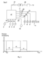
- a time diagram is shown. Accordingly, at the start of the program at the time t start, the control device 17 via the timer 26, the switch 25, whereby the display elements 7, 8, 9, 11 are supplied with electrical energy over the period of time .DELTA.t 1 . After the expiration of the period .DELTA.t 1 , the timer 26 opens the switches 25 in the signal lines 22, whereby the power supply to the display elements 7, 8, 9, 11 is interrupted for an indefinite period of time .DELTA.t 2 . On the other hand, the operation display element 15 continuously lights up regardless of the operating state of the display elements 7, 8, 9, 11.
- the indefinite period of time ⁇ t 2 is terminated when the operator actuates the information switching element 13, whereby the timer 26 is activated again and for the period ⁇ t 1, the switch 25 of the signal lines 22 closes.
- the timer 26 again interrupts the power supply to the display elements 7, 8, 9, 11, so that the washing program until the end of the program t is continued at non-activated display elements 7, 8, 9, 11.
- the 4 and 5 relate to the second embodiment. That in the Fig. 4
- the block diagram shown is essentially identical to the block diagram of FIG Fig. 2 so that its description can be referenced.
- Fig. 2 has been dispensed with the information switching element 13 in the second embodiment. Therefore, the operator can not manually restore a power supply of the display elements 7, 8, 9, 11 interrupted by the timer 26.
- timer 26 is shown in contrast, designed so that it closes at predetermined ON or OFF periods of time .DELTA.t and .DELTA.t from the switch 25 and opens.
- the display elements 7, 8, 9, 11 are supplied in a predetermined clock frequency with energy or the power supply is interrupted, as shown in the timing diagram of Fig. 5 is shown.
- the two embodiments can be combined as desired. So it may be particularly advantageous in terms of ease of use, in the Fig. 4 shown timer 26 additionally in the Fig. 2 Assign shown information element 13. In this way, on the one hand, the power supply to the display elements 7, 8, 9, 11 in the above-mentioned clock mode. On the other hand, can be restored to the display elements at any time, depending on the customer by pressing the information switching element 13, the power supply.
Abstract
Description
Die Erfindung betrifft ein Haushaltsgerät, insbesondere eine Geschirrspülmaschine, nach dem Oberbegriff des Patentanspruches 1.The invention relates to a domestic appliance, in particular a dishwasher, according to the preamble of
Moderne Haushaltsgeräte, insbesondere Geschirrspüler, sind heute mit einer Vielzahl von Anzeigen, d. h. LEDs bzw. LC-Displays, ausgestattet, die über eine elektrische Steuereinrichtung mit Energie versorgt werden.Modern home appliances, especially dishwashers, are today with a variety of ads, d. H. LEDs or LC displays equipped, which are powered by an electrical control device with energy.
Aus der
Die Schaltuhr-Anzeige ist während der gesamten Betriebsdauer kontinuierlich am elektrischen Versorgungsnetz angeschlossen. Andere Anzeigeelemente können teilweise auch vor einem Programmstart bzw. nach einem Programmende in Betrieb sein. Auf Dauer gesehen kann sich dadurch ein unerwünscht hoher Energieverbrauch ergeben.The time switch display is continuously connected to the electrical supply network throughout the entire operating period. Some of the display elements may also be in operation before a program start or after a program end. In the long term, this can result in an undesirably high energy consumption.
Das elektrische Haushaltsgerät der
Die Aufgabe der Erfindung besteht darin, ein Haushaltsgerät, insbesondere eine Geschirrspülmaschine, bereitzustellen, bei der der Energieverbrauch gesenkt ist.The object of the invention is to provide a domestic appliance, in particular a dishwasher, in which the energy consumption is reduced.
Die Aufgabe ist durch die Merkmale des Patentanspruches 1 gelöst. Bevorzugte Weiterentwicklungen der Erfindung sind in den Unteransprüchen offenbart.The object is solved by the features of
Gemäß dem Patentanspruch 1 reduziert die Steuereinrichtung nach einer vorgegebenen Zeitdauer die Energieversorgung zu dem Anzeigeelement. D. h. innerhalb dieser vorgegebenen Zeitdauer kann die Bedienperson die am Bedienelement vorgenommene Einstellung des Haushaltsgeräts anhand des mit elektrischer Energie versorgten Anzeigeelements, etwa einem LC-Display, überprüfen. Nach Ablauf der vorgegebenen Zeitdauer reduziert dann die Steuereinrichtung die Energieversorgung zum Anzeigeelement. Alternativ kann nach Ablauf der vorgegebenen Zeitdauer auch eine Minimalanzeige, z. B. eine LED, betrieben werden. Daraus ergibt sich auf Dauer gesehen eine erhebliche Energieeinsparung und damit auch eine verlängerte Lebensdauer für die Anzeigeelemente.According to
Bevorzugt kann die Steuereinrichtung das Anzeigeelement in vorgegebenen Taktintervallen mit Energie versorgen bzw. die Energieversorgung reduzieren. Auf diese Weise kann die Bedienperson auch nach Ablauf der vorgegebenen Zeitdauer Informationen über den Betriebszustand erhalten.Preferably, the control device can supply the display element with energy at predetermined clock intervals or reduce the power supply. In this way, the operator can receive information about the operating state even after the expiration of the predetermined period of time.
In einer weiteren Ausführungsform kann anstelle des o. g. Taktbetriebs der Anzeigeelemente oder in Kombination mit dem Taktbetrieb ein zusätzliches Informationsschaltelement vorgesehen sein. Bei dessen Betätigung kann nach Ablauf der vorgegebenen Zeitdauer die Steuereinrichtung die Energieversorgung zum Anzeigeelement wiederhergestellt werden. Das Informationsschaltelement kann zusammen mit den weiteren Bedien- und Anzeigeelementen in einem Bedienfeld des Haushaltsgeräts vorgesehen sein. Mit dem Informationsschaltelement kann - im Gegensatz zu den weiteren Bedienelementen - kein Betriebsparameter oder dergleichen eingestellt werden, sondern lediglich die Stromversorgung zu den Anzeigeelementen wiederhergestellt werden. Die Anzeigeelemente sind somit lediglich dann aufgeleuchtet bzw. aktiviert, wenn die Bedienperson durch Betätigung des Informationsschaltelements Informationen zum Betriebszustand einholen will. Entsprechend kann nach Betätigung des Informationsschaltelements die Steuereinrichtung nach einer weiteren, vorgegebenen Zeitdauer die Energieversorgung zum Anzeigeelement wieder reduzieren.In a further embodiment, an additional information switching element may be provided instead of the aforementioned clock mode of the display elements or in combination with the clock mode. Upon actuation of the control device, the power supply to the display element can be restored after the predetermined period of time. The information switching element can be provided together with the other operating and display elements in a control panel of the household appliance. With the information switching element can - in contrast to the other controls - no operating parameters or the like can be set, but only the power supply to the display elements are restored. The display elements are thus only lit or activated when the operator wants to obtain information about the operating state by operating the information switching element. Accordingly, after actuation of the information switching element, the control device can reduce the power supply to the display element again after a further, predetermined period of time.
Für eine einfache und zuverlässige Bedienbarkeit des Haushaltsgeräts kann bei einer Mehrzahl von Anzeigeelementen am Haushaltsgerät zumindest ein Betriebsanzeigeelement vorgesehen sein, das unabhängig von einer Betätigung des Informationsschaltelements den Betriebszustand des Haushaltsgeräts kontinuierlich anzeigt. Auf diese Weise ist gewährleistet, dass die Bedienperson auch bei einer Aus-Zeitdauer im oben beschriebenen Taktbetrieb bzw. nach Ablauf der oben erwähnten vorgegebenen Zeitdauer zumindest eine Rückmeldung darüber erhält, ob das Haushaltsgerät ein- oder ausgeschaltet ist. Bei einem weiteren, detaillierten Informationsbedarf kann die Bedienperson darüber hinaus das Informationsschaltelement bedienen, wodurch auch die verbleibenden Anzeigeelemente aufleuchten.For a simple and reliable operability of the household appliance can be provided at a plurality of display elements on the household appliance at least one operation display element, which displays the operating state of the household appliance continuously regardless of an operation of the information switching element. In this way it is ensured that the operator receives at least one feedback on whether the household appliance is switched on or off even with an off-duration in the above-described clock mode or after the expiry of the above-mentioned predetermined time. In a further, detailed information needs, the operator can also operate the information switching element, whereby the remaining display elements light up.
Nachfolgend sind zwei Ausführungsbeispiele der Erfindung anhand der beigefügten Figuren beschrieben.In the following, two embodiments of the invention will be described with reference to the attached figures.
Es zeigen
- Fig. 1
- in einer Vorderansicht eine Geschirrspülmaschine gemäß dem ersten Ausführungsbeispiel;
- Fig. 2
- stark schematisch in einem Blockschaltdiagramm eine Steuereinrichtung mit zugeordneten Bedien- und Anzeigeelementen;
- Fig. 3
- ein Zeitdiagramm zur Veranschaulichung der Betriebszustände der Anzei- geelemente;
- Fig. 4
- ein Blockschaltdiagramm gemäß dem zweiten Ausführungsbeispiel ent- sprechend der
Fig. 2 ; und - Fig. 5
- ein Zeitdiagramm entsprechend der
Fig. 3 .
- Fig. 1
- in a front view of a dishwasher according to the first embodiment;
- Fig. 2
- very schematically in a block diagram a control device with associated control and display elements;
- Fig. 3
- a timing chart for illustrating the operating states of the display elements;
- Fig. 4
- a block diagram according to the second embodiment according to the
Fig. 2 ; and - Fig. 5
- a timing diagram according to the
Fig. 3 ,
In der
Neben den oben erwähnten Bedien- und Anzeigeelementen ist darüber hinaus in der Bedienblende 1 ein später beschriebenes Informationsschaltelement 13 sowie ein Betriebsanzeigeelement 15 vorgesehen, das ebenfalls als eine LED-Anzeige ausgeführt ist. Zur Inbetriebnahme der Geschirrspülmaschine wird zunächst der Hauptschalter 3 gedrückt und dann ein entsprechendes Spülprogramm mittels der Bedienelemente 4, 5, 6 eingestellt. Bei Betätigung eines der Bedienelemente 4, 5, 6 startet das entsprechende Spülprogramm. Zusätzliche Informationen zum Spülprogramm sind im Anzeigedisplay 11 angezeigt.In addition to the above-mentioned control and display elements, a later-described
Wie aus der
Wie aus der
Nach einem durch Betätigung des Hauptschalters 3 sowie eines der Programmschalter 4, 5, 6 erfolgten Programmstarts steuert die Steuereinrichtung 17 über das Zeitglied 26 die Schalter 25 an, um die Signalleitungen 22 zu den Anzeigeelementen 7, 8, 9, 11 zu schließen. Auf diese Weise kann die Steuereinrichtung 17 über eine, vom Zeitglied 26 vorgegebene Zeitdauer Δt1 die Anzeigeelemente 7, 8, 9, 11 mit Energie versorgen. Nach Ablauf der vorgegebenen Zeitdauer Δt1 öffnet das Zeitglied 26 der Steuereinrichtung 17 die Schalter 25, so dass die Energieversorgung zu den Anzeigeelementen 7, 8, 9, 11 unterbrochen ist.After the program has been started by operating the
Nach Ablauf der vom Zeitglied 26 vorgegebenen Zeitdauer Δt1 kann die Bedienperson manuell das Informationsschaltelement 13 betätigen. Das Informationsschaltelement 13 ist über eine weitere Steuerleitung 28 mit dem Zeitglied 26 der Steuereinrichtung 17 in Verbindung. Durch manuelle Betätigung des Informationsschaltelements 13 kann das Zeitglied 26 erneut aktiviert werden, so dass es über die vorgegebene Zeitdauer Δt1 die Schalter 25 abermals geschlossen hält.After expiration of the time period .DELTA.t 1 given by the
In der
Die unbestimmte Zeitdauer Δt2 ist beendet, wenn die Bedienperson das Informationsschaltelement 13 betätigt, wodurch das Zeitglied 26 abermals aktiviert wird und für die Zeitdauer Δt1 die Schalter 25 der Signalleitungen 22 schließt.The indefinite period of time Δt 2 is terminated when the operator actuates the
Nach einem weiteren Ablauf des Zeitintervalls Δt1 unterbricht das Zeitglied 26 abermals die Energieversorgung zu den Anzeigeelementen 7, 8, 9, 11, so dass das Spülprogramm bis zum Programmendzeitpunkt tende bei nicht aktivierten Anzeigeelementen 7, 8, 9, 11 fortgesetzt wird.After a further expiration of the time interval .DELTA.t 1 , the
Die
Das in der
Die beiden Ausführungsbeispiele können beliebig miteinander kombiniert werden. So kann es bezüglich Bedienkomfort besonders vorteilhaft sein, dem in der
- 11
- Bedienblendecontrol panel
- 33
- Hauptschaltermain switch
- 4, 5, 64, 5, 6
- Programmschalterprogram switch
- 7, 8, 9, 117, 8, 9, 11
- Anzeigeelementeindicators
- 1313
- InformationsschaltelementInformation switching element
- 1515
- BetriebsanzeigeelementOperating indicator
- 1717
- Steuereinrichtungcontrol device
- 19, 22, 2319, 22, 23
- Signalleitungensignal lines
- 2525
- Schalterswitch
- 2626
- Zeitgliedtimer
- 27, 2827, 28
- Steuerleitungencontrol lines
- tstart t start
- Programmstartprogram start
- tende t end
- Programmendeend of program
- Δt1, Δtein, Δtaus .DELTA.t 1, a .DELTA.t, .DELTA.t from
- Zeitintervalletime intervals
Claims (6)
Applications Claiming Priority (2)
| Application Number | Priority Date | Filing Date | Title |
|---|---|---|---|
| DE102007058382A DE102007058382A1 (en) | 2007-12-05 | 2007-12-05 | Household appliance, in particular dishwasher |
| EP08857156A EP2217129A1 (en) | 2007-12-05 | 2008-11-05 | Household appliance, in particular dishwasher |
Related Parent Applications (1)
| Application Number | Title | Priority Date | Filing Date |
|---|---|---|---|
| EP08857156.7 Division | 2008-11-05 |
Publications (1)
| Publication Number | Publication Date |
|---|---|
| EP2258250A1 true EP2258250A1 (en) | 2010-12-08 |
Family
ID=40185034
Family Applications (3)
| Application Number | Title | Priority Date | Filing Date |
|---|---|---|---|
| EP10174760A Revoked EP2263511B1 (en) | 2007-12-05 | 2008-11-05 | Domestic appliance, particularly a dishwasher |
| EP10174759A Withdrawn EP2258250A1 (en) | 2007-12-05 | 2008-11-05 | Domestic appliance, particularly a dishwasher |
| EP08857156A Withdrawn EP2217129A1 (en) | 2007-12-05 | 2008-11-05 | Household appliance, in particular dishwasher |
Family Applications Before (1)
| Application Number | Title | Priority Date | Filing Date |
|---|---|---|---|
| EP10174760A Revoked EP2263511B1 (en) | 2007-12-05 | 2008-11-05 | Domestic appliance, particularly a dishwasher |
Family Applications After (1)
| Application Number | Title | Priority Date | Filing Date |
|---|---|---|---|
| EP08857156A Withdrawn EP2217129A1 (en) | 2007-12-05 | 2008-11-05 | Household appliance, in particular dishwasher |
Country Status (8)
| Country | Link |
|---|---|
| US (1) | US20100262315A1 (en) |
| EP (3) | EP2263511B1 (en) |
| CN (1) | CN101883517B (en) |
| AT (1) | ATE542464T1 (en) |
| DE (2) | DE102007058382A1 (en) |
| ES (1) | ES2378221T3 (en) |
| PL (1) | PL2263511T3 (en) |
| WO (1) | WO2009071411A1 (en) |
Families Citing this family (6)
| Publication number | Priority date | Publication date | Assignee | Title |
|---|---|---|---|---|
| DE102009045595A1 (en) * | 2009-10-12 | 2011-04-14 | BSH Bosch und Siemens Hausgeräte GmbH | Household appliance, in particular household dishwasher |
| DE102009045592A1 (en) * | 2009-10-12 | 2011-04-14 | BSH Bosch und Siemens Hausgeräte GmbH | Household appliance, in particular household dishwasher |
| DE102009045591A1 (en) * | 2009-10-12 | 2011-04-14 | BSH Bosch und Siemens Hausgeräte GmbH | Household appliance, in particular household dishwasher |
| DE102009045593A1 (en) | 2009-10-12 | 2011-04-14 | BSH Bosch und Siemens Hausgeräte GmbH | Household appliance, in particular household dishwasher |
| DE102009045590A1 (en) * | 2009-10-12 | 2011-04-14 | BSH Bosch und Siemens Hausgeräte GmbH | Household appliance, in particular household dishwasher |
| DE102009045594A1 (en) | 2009-10-12 | 2011-04-14 | BSH Bosch und Siemens Hausgeräte GmbH | Household appliance, in particular household dishwasher |
Citations (6)
| Publication number | Priority date | Publication date | Assignee | Title |
|---|---|---|---|---|
| US5151884A (en) * | 1992-03-02 | 1992-09-29 | Maytag Corporation | Control system for appliance indicator light and method for using same |
| DE4311935A1 (en) | 1993-04-10 | 1994-10-13 | Licentia Gmbh | Domestic appliance, in particular electric cooker or baking oven with cooker timer |
| DE19816749A1 (en) * | 1998-04-16 | 1999-10-21 | Abb Patent Gmbh | Electric appliance esp. installation appliance with operating and-or indicating elements and at least one illumination unit for illuminating or back illumination of operating |
| WO2003004753A1 (en) * | 2001-07-04 | 2003-01-16 | Lg Electronics Inc. | Internet-washer and operating method thereof |
| DE10236937A1 (en) | 2002-08-12 | 2004-02-26 | BSH Bosch und Siemens Hausgeräte GmbH | Operating panel for household device, e.g. washing machine, with movement detector to activate indicator displays and lights on panel only when user is nearby to save power |
| DE102006029708A1 (en) * | 2005-07-01 | 2007-02-01 | Lg Electronics Inc. | Controller for standby power drawn by washing machine, determines mains current supply in correspondence with user settings, on wash cycle completion |
Family Cites Families (8)
| Publication number | Priority date | Publication date | Assignee | Title |
|---|---|---|---|---|
| DE3204622A1 (en) * | 1982-02-10 | 1983-08-18 | Bosch-Siemens Hausgeräte GmbH, 7000 Stuttgart | Circuit arrangement for the illumination of indicating displays |
| DE4321101A1 (en) * | 1993-06-25 | 1995-01-05 | Miele & Cie | Domestic appliance having an electronic display |
| DE29602328U1 (en) * | 1996-02-10 | 1997-06-05 | Aeg Hausgeraete Gmbh | Household appliance with illuminants |
| US5789868A (en) * | 1996-08-13 | 1998-08-04 | The Lamson & Sessions Co. | Timed photocell switch circuit |
| KR100549304B1 (en) * | 2003-12-05 | 2006-02-02 | 엘지전자 주식회사 | Method and apparatus for controlling screen light of an image display device |
| US7499003B2 (en) * | 2004-03-31 | 2009-03-03 | Electrolux Home Products, Inc. | Disappearing interface system |
| DE102004063594A1 (en) * | 2004-12-30 | 2006-07-13 | BSH Bosch und Siemens Hausgeräte GmbH | Method for controlling the backlight of a display |
| TWI344594B (en) * | 2007-09-05 | 2011-07-01 | Wistron Corp | Power saving apparatus and method for a portable appliance |
-
2007
- 2007-12-05 DE DE102007058382A patent/DE102007058382A1/en not_active Withdrawn
-
2008
- 2008-11-05 AT AT10174760T patent/ATE542464T1/en active
- 2008-11-05 EP EP10174760A patent/EP2263511B1/en not_active Revoked
- 2008-11-05 WO PCT/EP2008/065004 patent/WO2009071411A1/en active Application Filing
- 2008-11-05 EP EP10174759A patent/EP2258250A1/en not_active Withdrawn
- 2008-11-05 US US12/745,698 patent/US20100262315A1/en not_active Abandoned
- 2008-11-05 EP EP08857156A patent/EP2217129A1/en not_active Withdrawn
- 2008-11-05 PL PL10174760T patent/PL2263511T3/en unknown
- 2008-11-05 DE DE202008018194U patent/DE202008018194U1/en not_active Expired - Lifetime
- 2008-11-05 CN CN2008801189846A patent/CN101883517B/en not_active Expired - Fee Related
- 2008-11-05 ES ES10174760T patent/ES2378221T3/en active Active
Patent Citations (6)
| Publication number | Priority date | Publication date | Assignee | Title |
|---|---|---|---|---|
| US5151884A (en) * | 1992-03-02 | 1992-09-29 | Maytag Corporation | Control system for appliance indicator light and method for using same |
| DE4311935A1 (en) | 1993-04-10 | 1994-10-13 | Licentia Gmbh | Domestic appliance, in particular electric cooker or baking oven with cooker timer |
| DE19816749A1 (en) * | 1998-04-16 | 1999-10-21 | Abb Patent Gmbh | Electric appliance esp. installation appliance with operating and-or indicating elements and at least one illumination unit for illuminating or back illumination of operating |
| WO2003004753A1 (en) * | 2001-07-04 | 2003-01-16 | Lg Electronics Inc. | Internet-washer and operating method thereof |
| DE10236937A1 (en) | 2002-08-12 | 2004-02-26 | BSH Bosch und Siemens Hausgeräte GmbH | Operating panel for household device, e.g. washing machine, with movement detector to activate indicator displays and lights on panel only when user is nearby to save power |
| DE102006029708A1 (en) * | 2005-07-01 | 2007-02-01 | Lg Electronics Inc. | Controller for standby power drawn by washing machine, determines mains current supply in correspondence with user settings, on wash cycle completion |
Also Published As
| Publication number | Publication date |
|---|---|
| PL2263511T3 (en) | 2012-07-31 |
| CN101883517A (en) | 2010-11-10 |
| US20100262315A1 (en) | 2010-10-14 |
| EP2263511A1 (en) | 2010-12-22 |
| ATE542464T1 (en) | 2012-02-15 |
| ES2378221T3 (en) | 2012-04-10 |
| DE202008018194U1 (en) | 2011-12-13 |
| EP2217129A1 (en) | 2010-08-18 |
| WO2009071411A1 (en) | 2009-06-11 |
| CN101883517B (en) | 2012-05-30 |
| DE102007058382A1 (en) | 2009-06-10 |
| EP2263511B1 (en) | 2012-01-25 |
Similar Documents
| Publication | Publication Date | Title |
|---|---|---|
| EP2263511B1 (en) | Domestic appliance, particularly a dishwasher | |
| DE19832757C2 (en) | Method for controlling a cooking appliance, a washing machine or a dishwasher and a cooking appliance, washing machine or dishwasher with a graphic display device | |
| WO2015075126A1 (en) | Domestic appliance | |
| EP2315866B1 (en) | Domestic appliance, especially a dishwasher or washing machine | |
| DE19746423C2 (en) | Electrical household appliance with demonstration mode | |
| DE10148453A1 (en) | Program-controlled household appliance with a display device | |
| EP2220737B1 (en) | Circuit configuration for operating a household appliance | |
| DE10203614B4 (en) | Method and operating device for operating a household appliance | |
| DE19624890A1 (en) | Washing machine with illuminating means | |
| WO2005102139A1 (en) | Dishwasher with optical operating cycle display | |
| EP0980929B2 (en) | Method and device to operate a program controlled domestic appliance | |
| EP0935099A2 (en) | Electrical household appliance with solar cell | |
| EP2488088B1 (en) | Household appliance, in particular a household dishwashing machine | |
| DE3737712C2 (en) | ||
| DE19924648A1 (en) | Programme controlled washing machine comprises control buttons and an acoustic display, with an acoustic signal when the buttons are actuated. | |
| DE102007058380A1 (en) | Circuit arrangement for operating e.g. washing machine, for doing laundry, has network part coupled with supply network by diodes using bistable contact element e.g. bistable relay, where element is controlled in closed condition of door | |
| EP2488090B1 (en) | Household appliance and method for operating a household appliance | |
| DE10337326B4 (en) | Method and control device for controlling a cooking appliance having at least one cooking zone | |
| DE3919947C2 (en) | ||
| DE102014110223A1 (en) | Vacuum cleaner with a display device and display device for a vacuum cleaner | |
| EP2488091B1 (en) | Household appliance, in particular a household dishwashing machine | |
| DE4104761A1 (en) | Display illuminating circuit for domestic equipment - saves power by deactivating main power stage and maintaining auxiliary sage during idle periods | |
| DE102011010615A1 (en) | Household appliance e.g. cooling and/or freezing apparatus, has comparison unit comparing operation duration of appliance with upper- and lower threshold values, so that function is activated when duration lies between threshold values | |
| DE20115646U1 (en) | Household electrical appliance with display device | |
| DE102004034871A1 (en) | Apparatus and method for ventilating a cooking place |
Legal Events
| Date | Code | Title | Description |
|---|---|---|---|
| PUAI | Public reference made under article 153(3) epc to a published international application that has entered the european phase |
Free format text: ORIGINAL CODE: 0009012 |
|
| AC | Divisional application: reference to earlier application |
Ref document number: 2217129 Country of ref document: EP Kind code of ref document: P |
|
| AK | Designated contracting states |
Kind code of ref document: A1 Designated state(s): AT BE BG CH CY CZ DE DK EE ES FI FR GB GR HR HU IE IS IT LI LT LU LV MC MT NL NO PL PT RO SE SI SK TR |
|
| AX | Request for extension of the european patent |
Extension state: AL BA MK RS |
|
| 17P | Request for examination filed |
Effective date: 20110608 |
|
| STAA | Information on the status of an ep patent application or granted ep patent |
Free format text: STATUS: THE APPLICATION IS DEEMED TO BE WITHDRAWN |
|
| 18D | Application deemed to be withdrawn |
Effective date: 20110609 |