EP2258146B1 - System and method for controlling leds - Google Patents
System and method for controlling leds Download PDFInfo
- Publication number
- EP2258146B1 EP2258146B1 EP09726563A EP09726563A EP2258146B1 EP 2258146 B1 EP2258146 B1 EP 2258146B1 EP 09726563 A EP09726563 A EP 09726563A EP 09726563 A EP09726563 A EP 09726563A EP 2258146 B1 EP2258146 B1 EP 2258146B1
- Authority
- EP
- European Patent Office
- Prior art keywords
- led
- leds
- pseudo
- value
- color
- Prior art date
- Legal status (The legal status is an assumption and is not a legal conclusion. Google has not performed a legal analysis and makes no representation as to the accuracy of the status listed.)
- Not-in-force
Links
Images


Classifications
-
- H—ELECTRICITY
- H05—ELECTRIC TECHNIQUES NOT OTHERWISE PROVIDED FOR
- H05B—ELECTRIC HEATING; ELECTRIC LIGHT SOURCES NOT OTHERWISE PROVIDED FOR; CIRCUIT ARRANGEMENTS FOR ELECTRIC LIGHT SOURCES, IN GENERAL
- H05B45/00—Circuit arrangements for operating light-emitting diodes [LED]
- H05B45/20—Controlling the colour of the light
Definitions
- the present invention generally relates to the generation of a light color by mixing a plurality of light emitting diodes (LEDs). More particularly, the invention is directed to the generation of a desired color and to the control of LEDs in order to obtain the desired color by mixing the light produced by the respective LEDs.
- LEDs light emitting diodes
- Prior art US 6552495 B1 discloses a control system for generating a desired light color on the basis of three red, green and blue LEDs.
- the system comprises a sensor for measuring the color coordinates of the light color generated by the three LEDs.
- a transformation module is adapted to convert said color coordinates to another color space. Reference color coordinates corresponding to the desired light and expressed in the second color space are provided by a further transformation module. Error color coordinates between the desired light color coordinates and the generated light color coordinates are then generated and fed to a driver module configured to generate drive signals I R , I G , I B for driving the LEDs.
- Prior art WO 2006/109237 A1 proposes to solve this problem and to increase the CRI of the generated color by using an LED module comprising more that three different LEDs.
- a fourth LED for example a white LED, the CRI index can be improved.
- the reference value of the desired color has only three coordinates X, Y, Z, while four output signals have to be produced to drive the three LEDs and the additional one.
- said prior art evaluates the position of the color coordinates of the desired color in the color space. More specifically, it is evaluated in which sub-triangle that can be produced in the color space by the four light sources the reference color is placed.
- the color diagram of Fig. 6 shows an example with five possible sub-triangles delimited by the points P0 to P5. Then the respectively fourth light source outside of the sub-triangle containing the reference color point Px is switched off, which results in three light sources being easily controlled in view of a tri-stimulus input signal.
- Prior art US 7315139 B1 discloses a light source including three LEDs controlled by a color controller with a color sensor including photodiodes for measuring the light generated by all three LEDs. Coefficients can be determined for a particular controller and set of LEDs by powering each LED separately and observing the signal from each of the photodiodes.
- the addition of a fourth LED requires the addition of a fourth photodiode and bandpass filter to allow the intensities of all four LEDs to be monitored so that the servo loop will maintain the LED intensities at the desired values as the LEDs age.
- the computational workload of such a system is significantly greater, which increases the cost.
- Prior art WO 02080625 A1 discloses a system for controlling a RBG based LED luminary which tracks the tristimulus values of both feedback and reference whereby the forward currents driving the LED luminary are adjusted in accordance with the errors between the feed tristimulus values and the reference tristimulus values until the errors are zero.
- a first aspect relates to a method for driving a plurality of at least four LEDs with differing spectra such that the superposition of the light emitted by the at least four LEDs results in light of a pre-set nominal color coordinate value
- the method comprises the step of determining the drive value for each LED by multiplying the nominal color coordinate value with the pseudo-inverse of a gain matrix representing, in color coordinates, the light output of each LED for a given drive value.
- Another aspect proposes a method for driving a plurality of at least four LEDs with differing spectra such that the superposition of the light emitted by the at least four LEDs results in light of a pre-set nominal color coordinate value, the method comprising the steps of:
- the method may furthermore comprise the step of
- the generated drive signals may be pulse-width modulated signals.
- the method may furthermore comprise the step of calculating and storing for the superimposed light of the at least four LEDs critical areas of the color space, wherein the pseudo-matrix multiplication would result in a drive value of less than zero for at least one LED.
- the pseudo-matrix multiplication step may be carried out only if said coordinate values are comprised in none of the calculated critical areas.
- the method may comprise the step of measuring the gain matrix.
- the measurement may be carried out in a start-up sequence while any feed-back loop is deactivated.
- the invention also relates to a computer software program product, performing a method according to any of the preceding steps when run on a computing device such as e.g. a microprocessor.
- the invention furthermore relates to an integrated circuit, such as e.g. an ASIC, which is designed to carry out a method a set forth above.
- an integrated circuit such as e.g. an ASIC, which is designed to carry out a method a set forth above.
- Another aspect relates to a system for driving a plurality of at least four LEDs with differing spectra such that the superposition of the light emitted by the at least four LEDs results in light of a pre-set nominal color coordinate value.
- the system comprises means for determining the drive value for each LED by multiplying the nominal color coordinate value with a pseudo- inverse of a gain matrix, the gain matrix representing, in color coordinates, the light output of each LED for a given drive value.
- the invention also proposes a system for driving a plurality of at least four LEDs with differing spectra such that the superposition of the light emitted by the at least four LEDs results in light of a pre-set nominal color coordinate value, the system comprising:
- the invention proposes a decoupling method by using the pseudo-inverse of the gain matrix.
- each of the four differing spectra preferably R, G, B, and any additional color
- each of the four differing spectra can be considered independently from each other as the respective contributions from one color to the other color are taking into account by a compensation factor which is given by the pseudo-inverse matrix.
- the four colors are switched on, without feedback loop and control, and via the color sensors the influence of the respectively four colors on the X, Y, Z coordinates are measured.
- the pseudo-inverse matrix is set up in the startup sequence.
- a PWM control is carried out.
- the invention also comprises an additional aspect in which beforehand critical areas in the CIE coordinate system are calculated.
- Critical areas are those areas where the pseudo-inverse matrix based control asks for contribution of a color of zero or even a negative value, which is physically impossible. If a reference color coordinate now is in one of these critical areas, the controller reduces the corresponding one of the at least for different colors to zero and then carries out the control using the remaining three using a 3x3 matrix mapping.
- This aspect reflects the problem that using the complete pseudo-matrix approach for the decoupling, in these critical areas either an instability of the control can occur or it takes longer iteration steps for the controller to reach the target color coordinate, as the controller has to overcome the physical constraint that a color can only be reduced to zero but no negative value - theoretically computed using the method - can be achieved.
- the CIE diagram will show a big portion in which, using the decoupling method, all four light sources or colors are active. At the border areas there will be the critical areas where one of the light sources or colors has to be switched off. Instead of the decoupling pseudo-inverse matrix, the simple three to three mapping will be carried out in order to calculate the control values for the remaining three other LEDs or colors. Actually, as in each of the critical areas one of the four light sources has to be completely switched off, a total of four 'alternative matrices' has to be computed. Actually, these alternative matrices are simply the complete decoupling matrix, in which one row corresponding to the color to be set to zero is entirely set to zero.
- Fig. 1 shows a control system 1 according to the invention and adapted to control a plurality of LEDs so as to generate a given light or light color.
- a control system 1 adapted to control a plurality of LEDs so as to generate a given light or light color.
- four LEDs having different spectra can be controlled.
- the four LEDs may consist in a red, a green and a blue LED together with an additional LED that may e.g. be a white LED.
- the plurality of LEDs is advantageously assembled together in an illumination device.
- the control system 1 is designed to map a nominal color coordinate to drive signals for the different LEDs.
- the control system 1 is designed to control (drive) the at least four different light sources such that the superposition of the at least four spectra results in light having a preset nominal color coordinate with values Xref, Yref, Zref describing a desired color in the so-called CIE 1931 XYZ color space or CIE 1931 color space that has been created by the Commission Internationale d'Eclairage (CIE) in 1931.
- CIE Commission Internationale d'Eclairage
- the tristimulus values can also be defined and given in an alternative three-component additive color model like in the CIE xyY, the CIE L*u*v* or the CIE L*a*b* color space.
- the reference coordinate values Xref, Yref, Zref of the desired color to be generated by the control system 1 can be stored in a memory or buffer 2 designed to store the color coordinates in the used color space which is here the CIE 1931 color space.
- the memory 2 is connected to a controller 3 that comprise e.g. a PI-controller 4 and a pseudo-inverse multiplier 5.
- the PI-controller or proportional-integral controller 4 is advantageously a diagonal PI-controller that is configured to output coordinate values cX, cY, cZ on the basis of the reference coordinate values Xref, Yref, Zref and actually measured color coordinates of the superimposed light emitted by the different LEDs, which measured color coordinates are fed back to the control system.
- Alternatively other known controllers can replace said PI-controller 4.
- the controller 3 is able to provide adapted control signals for driving the LEDs in order to achieve a desired color by mixing the LEDs outputs.
- the control signals can be control voltages or control currents for the LEDs.
- controller 3 defines the duty-cycles of pulse-width modulation (PWM) signals used to drive the LEDs.
- PWM pulse-width modulation
- the PWM control is preferably carried out in order to avoid problems caused by the intensity-dependence of the spectrum of an LED.
- the output of the PI-controller 4 is fed to the pseudo-inverse multiplier 5 that multiplies the coordinate values cX, cY, cZ with a matrix M -1 being the pseudo-inverse or generalized inverse of a matrix M representing the influence of the respective four colors generated by the four LEDs on the X, Y, Z coordinates.
- R G B A M - 1 ⁇ cX cY cZ with the matrix M -1 having the dimension 4*3.
- the calculated values R, G, B, A can be used for generating the PWM signals used to drive the LEDs.
- Said values R, G, B, A correspond to respective driving signals PWM R , PWM G , PWM B , PWM A for controlling the individual LEDs.
- an additional LED driver module (not shown) can be integrated in the system 1 to generate appropriate driving signals PWM R , PWM G , PWM B , PWM A for the RGBA LEDs on the basis of the calculated values R, G, B, A.
- the plant 6 comprises a multiplier 7 that multiplies the obtained R, G, B, A matrix with said M matrix, also called the gain matrix, in order to obtain the coordinate values X, Y, Z of the light generated by the four LEDs.
- Fig. 2 illustrates a startup sequence that is necessary in order to calculate the values of the pseudo-inverse matrix M -1 used in the controller 3.
- the first step S1 of the startup sequence is therefore to measure the influence of the spectrum generated by the red LED on the colors generated by the other green, blue and white LEDs. Likewise the respective influence of the spectrum generated by the green, blue and white LEDs on the other LEDs is measured.
- the four colors are switched on, without feedback loop and control.
- the influence of the respectively four colors on the X, Y, Z (e.g. RGB) coordinates are measured via color sensors (not shown).
- the measurement step S1 can be carried out at different moments.
- the measurement will take place during or after production of the LEDs and/or during production of said illumination device comprising the LEDs.
- the gain matrix M can be measured in a testing routine at startup or during the lifetime of the LEDs to take account of the possible modification of the spectrum generated by each LED. Most advantageously this measurement is carried out periodically during the lifetime of the LEDs.
- control actions can preferably be the PWM duty-cycles for each LED, i.e. for each channel, wherein the minimum possible value for such a control action is zero.
- the second embodiment now comprises an additional step of calculating S4 said critical areas in the CIE 1931 color space in order to avoid such time-consuming tracking.
- Fig. 3 shows a control system 1' according to the second embodiment of the invention and adapted to control the output of four LEDs to generate a desired mixed light/color.
- a memory 2' is adapted to store the color coordinates rx, ry, rY of the desired color according to the CIE xyY color space.
- the memory 2' is coupled to a first xyY to XYZ transformation module 10 for converting color coordinate values from the xyY to the XYZ color space so as to obtain new values Xref, Yref, Zref describing the desired or reference color.
- the output of said first transformation module 10 is connected to a feedback adder 11 that generates an error signal by subtracting coordinate values X, Y, Z generated by the control system 1', from the reference coordinate values Xref, Yref, Zref.
- a PI-controller 4 similar to that of the first embodiment then outputs the values ⁇ X, ⁇ Y, ⁇ Z.
- the color coordinates rx, ry, rY defining the desired color are also fed to a sectoring module 12 that has to verify whether or not the reference point defined by the coordinates rx, ry, rY is located within a critical area of the color space.
- This module 12 also performs the calculation S4 of said critical areas and preferably stores the result.
- a control unit 13 is connected to the output of the PI-controller 4 and to the output of the sectoring module 12.
- the control unit 13 receives from the sectoring module 12 information about the location of the desired color within the color space and whether the desired color is located in a critical area of the color space. More specifically the information received by the control unit 13 can define that all four LEDs or that only three LEDs shall be activated.
- the desired color is outside a critical area of the color space and the control unit 13 causes the pseudo-inverse multiplier 5 to multiply the coordinate values ⁇ X, ⁇ Y, ⁇ Z with the pseudo-inverse matrix M -1 of the first embodiment.
- the control unit 13 causes a multiplier 14 to multiply the coordinates ⁇ X, ⁇ Y, ⁇ Z with a modified pseudo-inverse matrix that has no contribution for the LED to be switched off.
- the system 1' also comprise the multiplier 7 of the first embodiment that multiplies the obtained R, G, B, A coordinates with the gain matrix M to obtain the values X, Y, Z that are sent to the feedback adder 11.
- the values X, Y, Z correspond to the actual colors produced by the LED module and are detected by a photosensor (not shown).
- the system 1' further comprise a second XYZ to xyY transformation module 15 for converting the values X, Y, Z into the xyY color space.
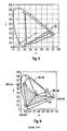
- Figs. 5 and 6 depict a given color gamut in a xyz color space diagram.
- the hatched area 50 corresponds to the critical area of the color space wherein the green LED is turned off according to the present invention.
- the corresponding area of the color space wherein the green LED is switched off according to the above mentioned prior art WO 2006/109237 A1 is the hatched area 60 of Fig. 6 .
- the transitions between the different areas of the color space are also smoother.
- Another advantage is that, upon applying the method of the invention, the LEDs are turned off only when necessary.
- the inventive controller 3, 5 can further store information about temperature and correct the driving of the LEDs accordingly.
- the computing the pseudo-inverse may be performed externally to the LED driving system.
- a calibration sequence can be done during or after production.
- a computer which is not part of the system itself and which may be connected only for the calibration procedure, can control the system and define the light output levels for the LEDs.
- the system can then set up a gain matrix representing, in color coordinates, the light output of each LED for the given drive values.
- the (external) personal computer can compute the pseudo-inverse of the gain matrix, and could also compute the drive values for each LED by multiplying the nominal color coordinate value with the pseudo-matrix.
- the computed results can then be stored in the system, for example in the controller 3 or the memory 2.
- the computing can be done partly in the personal computer, but it can be also done partly or completely within the system itself. While performing parts of the computing outside of the system, the demand on the controller 3 capabilities may be reduced.
Landscapes
- Circuit Arrangement For Electric Light Sources In General (AREA)
- Led Devices (AREA)
Abstract
Description
- The present invention generally relates to the generation of a light color by mixing a plurality of light emitting diodes (LEDs). More particularly, the invention is directed to the generation of a desired color and to the control of LEDs in order to obtain the desired color by mixing the light produced by the respective LEDs.
- Prior art
US 6552495 B1 discloses a control system for generating a desired light color on the basis of three red, green and blue LEDs. The system comprises a sensor for measuring the color coordinates of the light color generated by the three LEDs. A transformation module is adapted to convert said color coordinates to another color space. Reference color coordinates corresponding to the desired light and expressed in the second color space are provided by a further transformation module. Error color coordinates between the desired light color coordinates and the generated light color coordinates are then generated and fed to a driver module configured to generate drive signals IR, IG, IB for driving the LEDs. - However using only three LEDs to produce a color on the basis of only three basic colors (RGB) is disadvantageous since the color rendering index (CRI) of the mixed color is limited in view of the spectral gaps between the red, green and blue colors.
- Prior art
WO 2006/109237 A1 proposes to solve this problem and to increase the CRI of the generated color by using an LED module comprising more that three different LEDs. By adding a fourth LED, for example a white LED, the CRI index can be improved. - However the problem is now that the reference value of the desired color has only three coordinates X, Y, Z, while four output signals have to be produced to drive the three LEDs and the additional one. To overcome this problem said prior art evaluates the position of the color coordinates of the desired color in the color space. More specifically, it is evaluated in which sub-triangle that can be produced in the color space by the four light sources the reference color is placed. The color diagram of
Fig. 6 shows an example with five possible sub-triangles delimited by the points P0 to P5. Then the respectively fourth light source outside of the sub-triangle containing the reference color point Px is switched off, which results in three light sources being easily controlled in view of a tri-stimulus input signal. - Prior art
US 7315139 B1 discloses a light source including three LEDs controlled by a color controller with a color sensor including photodiodes for measuring the light generated by all three LEDs. Coefficients can be determined for a particular controller and set of LEDs by powering each LED separately and observing the signal from each of the photodiodes. The addition of a fourth LED requires the addition of a fourth photodiode and bandpass filter to allow the intensities of all four LEDs to be monitored so that the servo loop will maintain the LED intensities at the desired values as the LEDs age. The computational workload of such a system is significantly greater, which increases the cost. - Prior art
WO 02080625 A1 - Prior art "Colorimetric and Multispectral Image Acquisition Using Model-Based and Empirical Device Characterization" by Daniel Nyström, 15th Scandinavian Conference on Image Analysis, SCIA 2007, LNCS 4522, 10 June 2007- 14 June 2007, pages 798-807, Aalborg, Denmark, discloses an experimental image acquisition system, which besides trichromatic RGB filters also provides the possibility of acquiring multi-channel images using filters. To derive mappings to colorimetric and multispectral representations, a model-based characterization is disclosed in which the physical model describing the process by which the device captures color is inverted to reconstruct spectral reflectance.
- In this respect it is an object of the present invention to improve the control of a light module having at least four different light sources with differing spectra.
- A first aspect relates to a method for driving a plurality of at least four LEDs with differing spectra such that the superposition of the light emitted by the at least four LEDs results in light of a pre-set nominal color coordinate value The method comprises the step of determining the drive value for each LED by multiplying the nominal color coordinate value with the pseudo-inverse of a gain matrix representing, in color coordinates, the light output of each LED for a given drive value.
- Another aspect proposes a method for driving a plurality of at least four LEDs with differing spectra such that the superposition of the light emitted by the at least four LEDs results in light of a pre-set nominal color coordinate value, the method comprising the steps of:
- setting up a gain matrix representing, in color coordinates, the light output of each LED for a given drive value,
- computing the pseudo-inverse of the gain matrix, and
- computing the drive value for each LED by multiplying the nominal color coordinate value wit the pseudo-inverse of the gain matrix.
- The method may furthermore comprise the step of
- measuring the color coordinate of the light produced by the at least four LEDs, and
- computing the drive value for each LED by multiplying a value which is a function of the nominal color coordinate value and the actually measured value with the pseudo-inverse of the gain matrix.
- The generated drive signals may be pulse-width modulated signals.
- The method may furthermore comprise the step of calculating and storing for the superimposed light of the at least four LEDs critical areas of the color space, wherein the pseudo-matrix multiplication would result in a drive value of less than zero for at least one LED.
- The pseudo-matrix multiplication step may be carried out only if said coordinate values are comprised in none of the calculated critical areas.
- Any LED for which the pseudo-inverse multiplication would result in a negative control value can be switched off.
- The method may comprise the step of measuring the gain matrix.
- The measurement may be carried out in a start-up sequence while any feed-back loop is deactivated.
- The invention also relates to a computer software program product, performing a method according to any of the preceding steps when run on a computing device such as e.g. a microprocessor.
- The invention furthermore relates to an integrated circuit, such as e.g. an ASIC, which is designed to carry out a method a set forth above.
- Another aspect relates to a system for driving a plurality of at least four LEDs with differing spectra such that the superposition of the light emitted by the at least four LEDs results in light of a pre-set nominal color coordinate value. The system comprises means for determining the drive value for each LED by multiplying the nominal color coordinate value with a pseudo- inverse of a gain matrix, the gain matrix representing, in color coordinates, the light output of each LED for a given drive value.
- Finally, the invention also proposes a system for driving a plurality of at least four LEDs with differing spectra such that the superposition of the light emitted by the at least four LEDs results in light of a pre-set nominal color coordinate value,
the system comprising: - means for storing a gain matrix representing, in color coordinates, the light output of each LED for a given drive value,
- means for computing the pseudo-inverse of the gain matrix, and
- means for computing the drive value for each LED by multiplying the nominal color coordinate value with the pseudo-matrix.
- The invention proposes a decoupling method by using the pseudo-inverse of the gain matrix. Using the decoupling method, each of the four differing spectra (preferably R, G, B, and any additional color) can be considered independently from each other as the respective contributions from one color to the other color are taking into account by a compensation factor which is given by the pseudo-inverse matrix.
- When using the invention, whenever possible, all four (or more) colors will usually make some contribution, contrary to the prior art. However, it can not be excluded that in "extreme" color coordinate situations (i.e. when the desired nominal color coordinate to be produced is in the outer regions of the color coordinates), one light source or color has to be switched off. This occurs nevertheless less frequently in comparison to the prior art case. In order to calculate the values of the pseudo-inverse matrix, a startup sequence may be necessary, e.g. at the manufacturing side or periodically in use, in order to measure the gain matrix. Via this startup sequence, the gain matrix can be measured and then be stored in the controller (or the pseudo-inverse thereof is stored). E.g. by sequentially switching on the different LEDs, it can be measured how much a certain color spectrum influences the respectively other colors.
- In the startup sequence the four colors are switched on, without feedback loop and control, and via the color sensors the influence of the respectively four colors on the X, Y, Z coordinates are measured. Thus, the pseudo-inverse matrix is set up in the startup sequence. In order to avoid problems caused by the intensity-dependants of the spectrum of a LED, preferably a PWM control is carried out.
- The invention also comprises an additional aspect in which beforehand critical areas in the CIE coordinate system are calculated. Critical areas are those areas where the pseudo-inverse matrix based control asks for contribution of a color of zero or even a negative value, which is physically impossible. If a reference color coordinate now is in one of these critical areas, the controller reduces the corresponding one of the at least for different colors to zero and then carries out the control using the remaining three using a 3x3 matrix mapping. This aspect reflects the problem that using the complete pseudo-matrix approach for the decoupling, in these critical areas either an instability of the control can occur or it takes longer iteration steps for the controller to reach the target color coordinate, as the controller has to overcome the physical constraint that a color can only be reduced to zero but no negative value - theoretically computed using the method - can be achieved.
- Using this critical area approach, the CIE diagram will show a big portion in which, using the decoupling method, all four light sources or colors are active. At the border areas there will be the critical areas where one of the light sources or colors has to be switched off. Instead of the decoupling pseudo-inverse matrix, the simple three to three mapping will be carried out in order to calculate the control values for the remaining three other LEDs or colors. Actually, as in each of the critical areas one of the four light sources has to be completely switched off, a total of four 'alternative matrices' has to be computed. Actually, these alternative matrices are simply the complete decoupling matrix, in which one row corresponding to the color to be set to zero is entirely set to zero.
- The foregoing form as well as other forms, features and advantages of the invention will become further apparent from the following detailed description of the embodiments, read in conjunction with the accompanying drawings. The detailed description and drawings are merely illustrative of the invention rather than limiting, the scope of the invention being defined by the appended claims.
- Fig. 1
- shows a light control system according to a first embodiment of the present invention,
- Fig. 2
- describes a method according to the invention
- Fig. 3
- shows a second embodiment of the present invention,
- Fig. 4
- shows a color space diagram in accordance with the invention,
- Fig. 5
- shows a further color space diagram in accordance with the invention, and
- Fig. 6
- shows a color space diagram according to the prior art.
- With reference to
Fig. 1 a first embodiment of the present invention will be described in the followings. -
Fig. 1 shows acontrol system 1 according to the invention and adapted to control a plurality of LEDs so as to generate a given light or light color. In the particular embodiment ofFig. 1 , four LEDs having different spectra can be controlled. E.g. the four LEDs may consist in a red, a green and a blue LED together with an additional LED that may e.g. be a white LED. The plurality of LEDs is advantageously assembled together in an illumination device. - The
control system 1 is designed to map a nominal color coordinate to drive signals for the different LEDs. - The
control system 1 is designed to control (drive) the at least four different light sources such that the superposition of the at least four spectra results in light having a preset nominal color coordinate with values Xref, Yref, Zref describing a desired color in the so-called CIE 1931 XYZ color space or CIE 1931 color space that has been created by the Commission Internationale d'Eclairage (CIE) in 1931. Such combined values X, Y and Z are also referred to as the tristimulus values of a color and reflect the amounts of the three primary colors in the CIE 1931 color space. Even if the present embodiment bases on said color space, the tristimulus values can also be defined and given in an alternative three-component additive color model like in the CIE xyY, the CIE L*u*v* or the CIE L*a*b* color space. - The reference coordinate values Xref, Yref, Zref of the desired color to be generated by the
control system 1 can be stored in a memory orbuffer 2 designed to store the color coordinates in the used color space which is here the CIE 1931 color space. - The
memory 2 is connected to acontroller 3 that comprise e.g. a PI-controller 4 and apseudo-inverse multiplier 5. The PI-controller or proportional-integral controller 4 is advantageously a diagonal PI-controller that is configured to output coordinate values cX, cY, cZ on the basis of the reference coordinate values Xref, Yref, Zref and actually measured color coordinates of the superimposed light emitted by the different LEDs, which measured color coordinates are fed back to the control system. Alternatively other known controllers can replace said PI-controller 4. - The
controller 3 is able to provide adapted control signals for driving the LEDs in order to achieve a desired color by mixing the LEDs outputs. The control signals can be control voltages or control currents for the LEDs. Preferablycontroller 3 defines the duty-cycles of pulse-width modulation (PWM) signals used to drive the LEDs. The PWM control is preferably carried out in order to avoid problems caused by the intensity-dependence of the spectrum of an LED. - The output of the PI-
controller 4 is fed to thepseudo-inverse multiplier 5 that multiplies the coordinate values cX, cY, cZ with a matrix M-1 being the pseudo-inverse or generalized inverse of a matrix M representing the influence of the respective four colors generated by the four LEDs on the X, Y, Z coordinates. - The
pseudo-inverse multiplier 5 and therefore also thecontroller 3 of thesystem 1 output R, G, B, A values according to the following equation:
with the matrix M-1 having thedimension 4*3. - The calculated values R, G, B, A can be used for generating the PWM signals used to drive the LEDs. Said values R, G, B, A correspond to respective driving signals PWMR, PWMG, PWMB, PWMA for controlling the individual LEDs. Advantageously an additional LED driver module (not shown) can be integrated in the
system 1 to generate appropriate driving signals PWMR, PWMG, PWMB, PWMA for the RGBA LEDs on the basis of the calculated values R, G, B, A. - Applying this pseudo-inverse matrix M-1 at the output of the PI-
controller 4 will result in a decoupled system. In that way, each of the red, green, blue and additional colors can be considered independently from each other as the respective contribution from one color to the other color is taken into account by a compensation factor which is given by the pseudo-inverse matrix M-1. - The
plant 6 comprises amultiplier 7 that multiplies the obtained R, G, B, A matrix with said M matrix, also called the gain matrix, in order to obtain the coordinate values X, Y, Z of the light generated by the four LEDs. -
Fig. 2 illustrates a startup sequence that is necessary in order to calculate the values of the pseudo-inverse matrix M-1 used in thecontroller 3. - Within this startup sequence, it has to be measured S1 how much a certain color spectrum influences the respectively other colors. In the case of an RGBW system making use of red, green, blue and white LEDs, the first step S1 of the startup sequence is therefore to measure the influence of the spectrum generated by the red LED on the colors generated by the other green, blue and white LEDs. Likewise the respective influence of the spectrum generated by the green, blue and white LEDs on the other LEDs is measured.
- In the first step S1 of the startup sequence the four colors are switched on, without feedback loop and control. The influence of the respectively four colors on the X, Y, Z (e.g. RGB) coordinates are measured via color sensors (not shown).
- The result of those measures is put in the gain matrix M. This means that said gain matrix M comprises the influence factors measured in the first step S1.
- The measurement step S1 can be carried out at different moments. Advantageously the measurement will take place during or after production of the LEDs and/or during production of said illumination device comprising the LEDs. After this manufacturing step, the gain matrix M can be measured in a testing routine at startup or during the lifetime of the LEDs to take account of the possible modification of the spectrum generated by each LED. Most advantageously this measurement is carried out periodically during the lifetime of the LEDs.
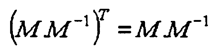
- Once the gain matrix M has been measured, the pseudo-inverse matrix M-1 is calculated S2. This calculation is performed for example according to a known mathematical method, such that the following equation is verified:

- The equations to be fulfilled by the pseudo-inverse matrix M-1 are:



- As a result the output of the
plant 6 corresponds to the coordinate values modified by the PI-controller 4:
- Once the matrix M-1 has been calculated, it is stored S3 in the
controller 3. - The above described embodiment can be generalized to a decoupling method using a pseudo-inverse control for controlling a number of n LEDs, which method can be defined by the equation:

wherein M is the gain matrix and PWM_LEDi is the PWM signal for driving the ith LED of the illumination system, the value of the PWM_LEDi signal being comprised between 0 and 1. - In the followings a second embodiment of the present invention will be described.
- The use of the
pseudo-inverse controller 3 of the first embodiment can result in control actions that are smaller than zero. As previously described the control actions can preferably be the PWM duty-cycles for each LED, i.e. for each channel, wherein the minimum possible value for such a control action is zero. - In other words they are areas of the CIE 1931 color space, which may be called critical areas, where the pseudo-inverse matrix M-1 based control according to the first embodiment asks for a color contribution of zero or below zero. Such a negative contribution is in fact physically impossible and results in a time-consuming tracking of a reference point located in such a critical area.
- The second embodiment now comprises an additional step of calculating S4 said critical areas in the CIE 1931 color space in order to avoid such time-consuming tracking.
-
Fig. 3 shows a control system 1' according to the second embodiment of the invention and adapted to control the output of four LEDs to generate a desired mixed light/color. - A memory 2' is adapted to store the color coordinates rx, ry, rY of the desired color according to the CIE xyY color space. The memory 2' is coupled to a first xyY to XYZ transformation module 10 for converting color coordinate values from the xyY to the XYZ color space so as to obtain new values Xref, Yref, Zref describing the desired or reference color.
- The output of said first transformation module 10 is connected to a
feedback adder 11 that generates an error signal by subtracting coordinate values X, Y, Z generated by the control system 1', from the reference coordinate values Xref, Yref, Zref. A PI-controller 4 similar to that of the first embodiment then outputs the values ΔX, ΔY, ΔZ. - The color coordinates rx, ry, rY defining the desired color are also fed to a
sectoring module 12 that has to verify whether or not the reference point defined by the coordinates rx, ry, rY is located within a critical area of the color space. Thismodule 12 also performs the calculation S4 of said critical areas and preferably stores the result. - A
control unit 13 is connected to the output of the PI-controller 4 and to the output of thesectoring module 12. Thecontrol unit 13 receives from thesectoring module 12 information about the location of the desired color within the color space and whether the desired color is located in a critical area of the color space. More specifically the information received by thecontrol unit 13 can define that all four LEDs or that only three LEDs shall be activated. - In case the four LEDs are to be used, the desired color is outside a critical area of the color space and the
control unit 13 causes thepseudo-inverse multiplier 5 to multiply the coordinate values ΔX, ΔY, ΔZ with the pseudo-inverse matrix M-1 of the first embodiment. The obtained RGBA coordinates are as follows:
- In case one of the LEDs has to be switched off because the desired color is in a critical area, the
control unit 13 causes amultiplier 14 to multiply the coordinates ΔX, ΔY, ΔZ with a modified pseudo-inverse matrix that has no contribution for the LED to be switched off. For example the corresponding modified pseudo-inverse matrix for switching off the red LED would be MR=o -1:
- The system 1' also comprise the
multiplier 7 of the first embodiment that multiplies the obtained R, G, B, A coordinates with the gain matrix M to obtain the values X, Y, Z that are sent to thefeedback adder 11. The values X, Y, Z correspond to the actual colors produced by the LED module and are detected by a photosensor (not shown). The system 1' further comprise a second XYZ to xyY transformation module 15 for converting the values X, Y, Z into the xyY color space. - In the followings the step of calculating S4 said critical areas in the CIE 1931 color space, which can be performed by the
sectoring module 12, will be described. - The critical areas, where respectively the red (R), green (G), blue (B) or additional (A) LED is turned-off, can be defined by following equations:


- For calculating the critical area in which the red LED is turned off, following equation has to be considered:

- The X and Z coordinates can be replaced by the CIE xyY coordinates as follows:


- By solving this equation one obtains:

- This equation defines the critical area with the red LED turned off, which is shown under reference A4 in
Fig. 4 . Similar reasoning applies to the other critical areas. - The advantages of the present invention over the prior art can be seen on
Figs. 5 and 6 that depict a given color gamut in a xyz color space diagram. The hatchedarea 50 corresponds to the critical area of the color space wherein the green LED is turned off according to the present invention. - The corresponding area of the color space wherein the green LED is switched off according to the above mentioned prior art
WO 2006/109237 A1 is the hatchedarea 60 ofFig. 6 . - The fact that the hatched
area - The transitions between the different areas of the color space are also smoother.
- Another advantage is that, upon applying the method of the invention, the LEDs are turned off only when necessary.
- The
inventive controller - The computing the pseudo-inverse may be performed externally to the LED driving system. For example, a calibration sequence can be done during or after production. A computer, which is not part of the system itself and which may be connected only for the calibration procedure, can control the system and define the light output levels for the LEDs. The system can then set up a gain matrix representing, in color coordinates, the light output of each LED for the given drive values. Then the (external) personal computer can compute the pseudo-inverse of the gain matrix, and could also compute the drive values for each LED by multiplying the nominal color coordinate value with the pseudo-matrix. The computed results can then be stored in the system, for example in the
controller 3 or thememory 2. The computing can be done partly in the personal computer, but it can be also done partly or completely within the system itself. While performing parts of the computing outside of the system, the demand on thecontroller 3 capabilities may be reduced.
Claims (20)
- A method for driving a plurality of at least four LEDs with differing spectra such that the superposition of the light emitted by the at least four LEDs results in light of a pre-set nominal color coordinate value,
the method comprising the step of determining the drive value for each LED characterized in that the step of determining the drive value for each LED is carried out by multiplying the nominal color coordinate value with the pseudo-inverse (M -1) of a gain matrix (M)representing, in color coordinates, the light output of each LED for a given drive value. - The method according to claim 1,
the method comprising the steps of:- setting up a gain matrix representing, in color coordinates, the light output of each LED for a given drive value,- computing (S2) the pseudo-inverse of the gain matrix, and- computing the drive value for each LED by multiplying the nominal color coordinate value with the pseudo-inverse matrix. - The method according to claim 1 or 2,
comprising the step of- measuring the color coordinate of the light produced by the at least four LEDs, and- computing the drive value for each LED by multiplying a value which is a function of the nominal color coordinate value and the actually measured value with the pseudo-matrix. - A method according to any of the preceding claims,
wherein the generated drive signals (PWMR, PWMG, PWMB, PWMA) are pulse-width modulation signals. - A method according to claim 3 or 4,
comprising calculating (S4) for the superimposed light of the at least four LEDs critical areas of the color space, wherein the pseudo-matrix multiplication would result in a drive value of less than zero for at least one LED. - A method according to claim 5,
wherein the pseudo-matrix multiplication step is carried out only if said coordinate values are comprised in none of the calculated critical areas. - A method according to claim 5 or 6,
wherein any LED for which the pseudo-inverse multiplication would result in a negative control value is switched off. - A method according to anyone of the preceding claims, comprising the step of measuring (S1) the gain matrix (M).
- The method according to claim 8,
wherein the measurement is carried out in a start-up sequence while any feed-back loop is deactivated. - A computer software program product,
performing a method according to any of the preceding steps when run on a computing device such as e.g. a microprocessor. - An integrated circuit, such as e.g. an ASIC, comprising means for carrying out a method according to any of claims 1 to 9.
- A system (1) for driving a plurality of at least four LEDs with differing spectra such that the superposition of the light emitted by the at least four LEDs results in light of a pre-set nominal color coordinate value, the system comprising means for determining the drive value for each LED characterized in that said means are adapted to determine the drive value for each LED by multiplying the nominal color coordinate value with a pseudo- inverse (M -1) of a gain matrix (M), the gain matrix (M) representing, in color coordinates, the light output of each LED for a given drive value.
- The system according to claim 12,
comprising- color sensors for measuring the color coordinate of the light produced by the at least four LEDs, and- means for computing the drive value for each LED by multiplying a value which is a function of the nominal color coordinate value and the actually measured value with the pseudo-matrix. - The system according to claim 12 or 13,
comprising a PWM drive unit, supplied wit the drive values and performing a PWM driving of the LEDs, wherein the duty cycle of the PWM drive depends on the supplied drive values. - The system according to any of claims 12 to 14, comprising means for storing for the superimposed light of the at least four LEDs critical areas of the color space, wherein the pseudo-matrix multiplication would result in a drive value of less than zero for at least one LED.
- The system according to claim 15,
which is designed to perform the pseudo-matrix multiplication step only if said coordinate values are comprised in none of the calculated critical areas. - The system according to claim 15 or 16,
wherein any LED for which the pseudo-inverse multiplication would result in a negative control value is switched off. - The system according to anyone of claims 12 to 17, comprising means for measuring (S1) the gain matrix (M).
- The system according to claim 18 ,
designed for carrying out the measurement of the gain matrix in a start-up sequence while any feed-back loop is deactivated. - The system according to anyone of claims 12 to 19, where at least a part of the computing is performed externally of the system itself.
Applications Claiming Priority (2)
| Application Number | Priority Date | Filing Date | Title |
|---|---|---|---|
| DE102008016756A DE102008016756A1 (en) | 2008-03-31 | 2008-03-31 | Arrangement and method for controlling LEDs |
| PCT/EP2009/002296 WO2009121539A1 (en) | 2008-03-31 | 2009-03-30 | System and method for controlling leds |
Publications (2)
| Publication Number | Publication Date |
|---|---|
| EP2258146A1 EP2258146A1 (en) | 2010-12-08 |
| EP2258146B1 true EP2258146B1 (en) | 2012-05-23 |
Family
ID=40887379
Family Applications (1)
| Application Number | Title | Priority Date | Filing Date |
|---|---|---|---|
| EP09726563A Not-in-force EP2258146B1 (en) | 2008-03-31 | 2009-03-30 | System and method for controlling leds |
Country Status (3)
| Country | Link |
|---|---|
| EP (1) | EP2258146B1 (en) |
| DE (1) | DE102008016756A1 (en) |
| WO (1) | WO2009121539A1 (en) |
Cited By (1)
| Publication number | Priority date | Publication date | Assignee | Title |
|---|---|---|---|---|
| EP4486198A4 (en) * | 2022-03-01 | 2026-01-14 | Mimosa Diagnostics Inc | Deployable portable imaging device for multispectral tissue assessment |
Families Citing this family (37)
| Publication number | Priority date | Publication date | Assignee | Title |
|---|---|---|---|---|
| US8841864B2 (en) | 2011-12-05 | 2014-09-23 | Biological Illumination, Llc | Tunable LED lamp for producing biologically-adjusted light |
| US8547391B2 (en) * | 2011-05-15 | 2013-10-01 | Lighting Science Group Corporation | High efficacy lighting signal converter and associated methods |
| US9024536B2 (en) | 2011-12-05 | 2015-05-05 | Biological Illumination, Llc | Tunable LED lamp for producing biologically-adjusted light and associated methods |
| US9532423B2 (en) | 2010-07-23 | 2016-12-27 | Lighting Science Group Corporation | System and methods for operating a lighting device |
| US9827439B2 (en) | 2010-07-23 | 2017-11-28 | Biological Illumination, Llc | System for dynamically adjusting circadian rhythm responsive to scheduled events and associated methods |
| US8760370B2 (en) | 2011-05-15 | 2014-06-24 | Lighting Science Group Corporation | System for generating non-homogenous light and associated methods |
| US8686641B2 (en) | 2011-12-05 | 2014-04-01 | Biological Illumination, Llc | Tunable LED lamp for producing biologically-adjusted light |
| US8743023B2 (en) | 2010-07-23 | 2014-06-03 | Biological Illumination, Llc | System for generating non-homogenous biologically-adjusted light and associated methods |
| US9681522B2 (en) | 2012-05-06 | 2017-06-13 | Lighting Science Group Corporation | Adaptive light system and associated methods |
| US8401231B2 (en) | 2010-11-09 | 2013-03-19 | Biological Illumination, Llc | Sustainable outdoor lighting system for use in environmentally photo-sensitive area |
| US8729832B2 (en) | 2011-05-15 | 2014-05-20 | Lighting Science Group Corporation | Programmable luminaire system |
| US8901850B2 (en) | 2012-05-06 | 2014-12-02 | Lighting Science Group Corporation | Adaptive anti-glare light system and associated methods |
| US9173269B2 (en) | 2011-05-15 | 2015-10-27 | Lighting Science Group Corporation | Lighting system for accentuating regions of a layer and associated methods |
| US8754832B2 (en) | 2011-05-15 | 2014-06-17 | Lighting Science Group Corporation | Lighting system for accenting regions of a layer and associated methods |
| US8847436B2 (en) | 2011-09-12 | 2014-09-30 | Lighting Science Group Corporation | System for inductively powering an electrical device and associated methods |
| US9913341B2 (en) | 2011-12-05 | 2018-03-06 | Biological Illumination, Llc | LED lamp for producing biologically-adjusted light including a cyan LED |
| US8866414B2 (en) | 2011-12-05 | 2014-10-21 | Biological Illumination, Llc | Tunable LED lamp for producing biologically-adjusted light |
| US8963450B2 (en) | 2011-12-05 | 2015-02-24 | Biological Illumination, Llc | Adaptable biologically-adjusted indirect lighting device and associated methods |
| US9220202B2 (en) | 2011-12-05 | 2015-12-29 | Biological Illumination, Llc | Lighting system to control the circadian rhythm of agricultural products and associated methods |
| US9289574B2 (en) | 2011-12-05 | 2016-03-22 | Biological Illumination, Llc | Three-channel tuned LED lamp for producing biologically-adjusted light |
| DE102012003018B4 (en) | 2012-02-15 | 2016-08-11 | Diehl Aerospace Gmbh | Method for producing light of a desired light color by means of light-emitting diodes |
| US9366409B2 (en) | 2012-05-06 | 2016-06-14 | Lighting Science Group Corporation | Tunable lighting apparatus |
| US9402294B2 (en) | 2012-05-08 | 2016-07-26 | Lighting Science Group Corporation | Self-calibrating multi-directional security luminaire and associated methods |
| US9006987B2 (en) | 2012-05-07 | 2015-04-14 | Lighting Science Group, Inc. | Wall-mountable luminaire and associated systems and methods |
| US8680457B2 (en) | 2012-05-07 | 2014-03-25 | Lighting Science Group Corporation | Motion detection system and associated methods having at least one LED of second set of LEDs to vary its voltage |
| DE102012209252A1 (en) * | 2012-05-31 | 2013-12-05 | Hella Kgaa Hueck & Co. | Method for calibrating illumination device for illuminating e.g. interior arrangement elements in motor car, involves generating drive signal from output value to control respective light source of illumination device |
| US9174067B2 (en) | 2012-10-15 | 2015-11-03 | Biological Illumination, Llc | System for treating light treatable conditions and associated methods |
| DE102013201915A1 (en) | 2012-10-31 | 2014-05-15 | Tridonic Jennersdorf Gmbh | Method and arrangement for controlling LEDs |
| US9347655B2 (en) | 2013-03-11 | 2016-05-24 | Lighting Science Group Corporation | Rotatable lighting device |
| US9353935B2 (en) | 2013-03-11 | 2016-05-31 | Lighting Science Group, Corporation | Rotatable lighting device |
| US9018854B2 (en) | 2013-03-14 | 2015-04-28 | Biological Illumination, Llc | Lighting system with reduced physioneural compression and associate methods |
| US9151453B2 (en) | 2013-03-15 | 2015-10-06 | Lighting Science Group Corporation | Magnetically-mountable lighting device and associated systems and methods |
| US9222653B2 (en) | 2013-03-15 | 2015-12-29 | Lighting Science Group Corporation | Concave low profile luminaire with magnetic lighting devices and associated systems and methods |
| US20140268731A1 (en) | 2013-03-15 | 2014-09-18 | Lighting Science Group Corpporation | Low bay lighting system and associated methods |
| US9157618B2 (en) | 2013-03-15 | 2015-10-13 | Lighting Science Group Corporation | Trough luminaire with magnetic lighting devices and associated systems and methods |
| DE102013010512B4 (en) | 2013-06-22 | 2015-05-28 | Diehl Aerospace Gmbh | Arrangement with at least one metameric lighting device and passenger cabin |
| CN107454718B (en) * | 2017-08-31 | 2023-11-28 | 广州光联电子科技有限公司 | An LED light source and optical system with color temperature correction function |
Family Cites Families (7)
| Publication number | Priority date | Publication date | Assignee | Title |
|---|---|---|---|---|
| EP0760223A1 (en) * | 1995-08-31 | 1997-03-05 | Hewlett-Packard GmbH | Apparatus for monitoring, in particular pulse oximeter |
| US6205244B1 (en) * | 1998-06-23 | 2001-03-20 | Intel Corporation | Method for imager device color calibration utilizing light-emitting diodes or other spectral light sources |
| DE10040620B4 (en) * | 1999-08-21 | 2006-08-10 | Maryniak, André, Dr.-Ing. | Method for controlling or regulating a unit to be controlled |
| US6507159B2 (en) * | 2001-03-29 | 2003-01-14 | Koninklijke Philips Electronics N.V. | Controlling method and system for RGB based LED luminary |
| US6552495B1 (en) | 2001-12-19 | 2003-04-22 | Koninklijke Philips Electronics N.V. | Adaptive control system and method with spatial uniform color metric for RGB LED based white light illumination |
| CN100566484C (en) | 2005-04-14 | 2009-12-02 | 皇家飞利浦电子股份有限公司 | Color control of white LED lights |
| US7315139B1 (en) * | 2006-11-30 | 2008-01-01 | Avago Technologis Ecbu Ip (Singapore) Pte Ltd | Light source having more than three LEDs in which the color points are maintained using a three channel color sensor |
-
2008
- 2008-03-31 DE DE102008016756A patent/DE102008016756A1/en not_active Withdrawn
-
2009
- 2009-03-30 WO PCT/EP2009/002296 patent/WO2009121539A1/en not_active Ceased
- 2009-03-30 EP EP09726563A patent/EP2258146B1/en not_active Not-in-force
Cited By (1)
| Publication number | Priority date | Publication date | Assignee | Title |
|---|---|---|---|---|
| EP4486198A4 (en) * | 2022-03-01 | 2026-01-14 | Mimosa Diagnostics Inc | Deployable portable imaging device for multispectral tissue assessment |
Also Published As
| Publication number | Publication date |
|---|---|
| EP2258146A1 (en) | 2010-12-08 |
| DE102008016756A1 (en) | 2009-10-01 |
| WO2009121539A1 (en) | 2009-10-08 |
Similar Documents
| Publication | Publication Date | Title |
|---|---|---|
| WO2009121539A1 (en) | System and method for controlling leds | |
| EP2860721B1 (en) | Calibration of displays having spatially-variable backlight | |
| US6411046B1 (en) | Effective modeling of CIE xy coordinates for a plurality of LEDs for white LED light control | |
| CN100544531C (en) | Control system for a lighting device including discrete light sources | |
| CA2708978C (en) | Luminaire control system and method | |
| US8593481B2 (en) | Method and arrangement for setting a color locus, and luminous system | |
| EP1943880B1 (en) | Led luminary system | |
| US6507159B2 (en) | Controlling method and system for RGB based LED luminary | |
| JP5071834B2 (en) | Lighting device and adjustment method | |
| EP2378840B1 (en) | Lighting apparatus and method for controlling the same | |
| US8823630B2 (en) | Systems and methods for providing color management control in a lighting panel | |
| US20080290251A1 (en) | Led Lighting System and Control Method | |
| US20090066631A1 (en) | Backlight control system and method using dither sampling | |
| US20030111533A1 (en) | RGB led based white light control system with quasi-uniform color metric | |
| CN101467490A (en) | Led backlight for LCD with color uniformity recalibration over lifetime | |
| WO2007069149A1 (en) | Illumination device and method for controlling an illumination device | |
| WO2008139369A1 (en) | Lighting device with a plurality of light emitters | |
| US20090078852A1 (en) | Chrominance compensation method and panel lightening method in a display apparatus | |
| EP3065508B1 (en) | Methods of controlling RGBW lamps, RGBW lamps and controller therefor | |
| KR101531378B1 (en) | Luminaire control system and method | |
| Lohaus et al. | Advanced color control for multicolor LED illumination systems with parametric optimization | |
| US7948499B2 (en) | Color control algorithm for use in display systems | |
| EP2429262A2 (en) | Light generating device and method for controlling the device | |
| US20230262855A1 (en) | Illuminant device for emitting light of a continuously adjustable colour, in particular for individualizing and/or illuminating an interior space | |
| KR20160099402A (en) | Lighting apparatus controlling light flux and method for controlling same |
Legal Events
| Date | Code | Title | Description |
|---|---|---|---|
| PUAI | Public reference made under article 153(3) epc to a published international application that has entered the european phase |
Free format text: ORIGINAL CODE: 0009012 |
|
| 17P | Request for examination filed |
Effective date: 20100915 |
|
| AK | Designated contracting states |
Kind code of ref document: A1 Designated state(s): AT BE BG CH CY CZ DE DK EE ES FI FR GB GR HR HU IE IS IT LI LT LU LV MC MK MT NL NO PL PT RO SE SI SK TR |
|
| AX | Request for extension of the european patent |
Extension state: AL BA RS |
|
| RIN1 | Information on inventor provided before grant (corrected) |
Inventor name: BETSCHART, ADRIAN Inventor name: PEREIRA, EDUARDO Inventor name: ZIMMERMANN, MICHAEL Inventor name: SCHENKER, YVES |
|
| 17Q | First examination report despatched |
Effective date: 20110606 |
|
| DAX | Request for extension of the european patent (deleted) | ||
| GRAP | Despatch of communication of intention to grant a patent |
Free format text: ORIGINAL CODE: EPIDOSNIGR1 |
|
| GRAS | Grant fee paid |
Free format text: ORIGINAL CODE: EPIDOSNIGR3 |
|
| GRAA | (expected) grant |
Free format text: ORIGINAL CODE: 0009210 |
|
| AK | Designated contracting states |
Kind code of ref document: B1 Designated state(s): AT BE BG CH CY CZ DE DK EE ES FI FR GB GR HR HU IE IS IT LI LT LU LV MC MK MT NL NO PL PT RO SE SI SK TR |
|
| REG | Reference to a national code |
Ref country code: GB Ref legal event code: FG4D |
|
| REG | Reference to a national code |
Ref country code: CH Ref legal event code: EP |
|
| REG | Reference to a national code |
Ref country code: AT Ref legal event code: REF Ref document number: 559603 Country of ref document: AT Kind code of ref document: T Effective date: 20120615 |
|
| REG | Reference to a national code |
Ref country code: IE Ref legal event code: FG4D |
|
| REG | Reference to a national code |
Ref country code: DE Ref legal event code: R096 Ref document number: 602009007224 Country of ref document: DE Effective date: 20120719 |
|
| REG | Reference to a national code |
Ref country code: NL Ref legal event code: VDEP Effective date: 20120523 |
|
| REG | Reference to a national code |
Ref country code: LT Ref legal event code: MG4D Effective date: 20120523 |
|
| PG25 | Lapsed in a contracting state [announced via postgrant information from national office to epo] |
Ref country code: FI Free format text: LAPSE BECAUSE OF FAILURE TO SUBMIT A TRANSLATION OF THE DESCRIPTION OR TO PAY THE FEE WITHIN THE PRESCRIBED TIME-LIMIT Effective date: 20120523 Ref country code: CY Free format text: LAPSE BECAUSE OF FAILURE TO SUBMIT A TRANSLATION OF THE DESCRIPTION OR TO PAY THE FEE WITHIN THE PRESCRIBED TIME-LIMIT Effective date: 20120523 Ref country code: SE Free format text: LAPSE BECAUSE OF FAILURE TO SUBMIT A TRANSLATION OF THE DESCRIPTION OR TO PAY THE FEE WITHIN THE PRESCRIBED TIME-LIMIT Effective date: 20120523 Ref country code: LT Free format text: LAPSE BECAUSE OF FAILURE TO SUBMIT A TRANSLATION OF THE DESCRIPTION OR TO PAY THE FEE WITHIN THE PRESCRIBED TIME-LIMIT Effective date: 20120523 Ref country code: IS Free format text: LAPSE BECAUSE OF FAILURE TO SUBMIT A TRANSLATION OF THE DESCRIPTION OR TO PAY THE FEE WITHIN THE PRESCRIBED TIME-LIMIT Effective date: 20120923 Ref country code: NO Free format text: LAPSE BECAUSE OF FAILURE TO SUBMIT A TRANSLATION OF THE DESCRIPTION OR TO PAY THE FEE WITHIN THE PRESCRIBED TIME-LIMIT Effective date: 20120823 |
|
| PG25 | Lapsed in a contracting state [announced via postgrant information from national office to epo] |
Ref country code: HR Free format text: LAPSE BECAUSE OF FAILURE TO SUBMIT A TRANSLATION OF THE DESCRIPTION OR TO PAY THE FEE WITHIN THE PRESCRIBED TIME-LIMIT Effective date: 20120523 Ref country code: LV Free format text: LAPSE BECAUSE OF FAILURE TO SUBMIT A TRANSLATION OF THE DESCRIPTION OR TO PAY THE FEE WITHIN THE PRESCRIBED TIME-LIMIT Effective date: 20120523 Ref country code: GR Free format text: LAPSE BECAUSE OF FAILURE TO SUBMIT A TRANSLATION OF THE DESCRIPTION OR TO PAY THE FEE WITHIN THE PRESCRIBED TIME-LIMIT Effective date: 20120824 Ref country code: SI Free format text: LAPSE BECAUSE OF FAILURE TO SUBMIT A TRANSLATION OF THE DESCRIPTION OR TO PAY THE FEE WITHIN THE PRESCRIBED TIME-LIMIT Effective date: 20120523 Ref country code: PT Free format text: LAPSE BECAUSE OF FAILURE TO SUBMIT A TRANSLATION OF THE DESCRIPTION OR TO PAY THE FEE WITHIN THE PRESCRIBED TIME-LIMIT Effective date: 20120924 |
|
| PG25 | Lapsed in a contracting state [announced via postgrant information from national office to epo] |
Ref country code: BE Free format text: LAPSE BECAUSE OF FAILURE TO SUBMIT A TRANSLATION OF THE DESCRIPTION OR TO PAY THE FEE WITHIN THE PRESCRIBED TIME-LIMIT Effective date: 20120523 |
|
| PG25 | Lapsed in a contracting state [announced via postgrant information from national office to epo] |
Ref country code: EE Free format text: LAPSE BECAUSE OF FAILURE TO SUBMIT A TRANSLATION OF THE DESCRIPTION OR TO PAY THE FEE WITHIN THE PRESCRIBED TIME-LIMIT Effective date: 20120523 Ref country code: CZ Free format text: LAPSE BECAUSE OF FAILURE TO SUBMIT A TRANSLATION OF THE DESCRIPTION OR TO PAY THE FEE WITHIN THE PRESCRIBED TIME-LIMIT Effective date: 20120523 Ref country code: DK Free format text: LAPSE BECAUSE OF FAILURE TO SUBMIT A TRANSLATION OF THE DESCRIPTION OR TO PAY THE FEE WITHIN THE PRESCRIBED TIME-LIMIT Effective date: 20120523 Ref country code: SK Free format text: LAPSE BECAUSE OF FAILURE TO SUBMIT A TRANSLATION OF THE DESCRIPTION OR TO PAY THE FEE WITHIN THE PRESCRIBED TIME-LIMIT Effective date: 20120523 Ref country code: NL Free format text: LAPSE BECAUSE OF FAILURE TO SUBMIT A TRANSLATION OF THE DESCRIPTION OR TO PAY THE FEE WITHIN THE PRESCRIBED TIME-LIMIT Effective date: 20120523 Ref country code: RO Free format text: LAPSE BECAUSE OF FAILURE TO SUBMIT A TRANSLATION OF THE DESCRIPTION OR TO PAY THE FEE WITHIN THE PRESCRIBED TIME-LIMIT Effective date: 20120523 |
|
| PG25 | Lapsed in a contracting state [announced via postgrant information from national office to epo] |
Ref country code: IT Free format text: LAPSE BECAUSE OF FAILURE TO SUBMIT A TRANSLATION OF THE DESCRIPTION OR TO PAY THE FEE WITHIN THE PRESCRIBED TIME-LIMIT Effective date: 20120523 Ref country code: PL Free format text: LAPSE BECAUSE OF FAILURE TO SUBMIT A TRANSLATION OF THE DESCRIPTION OR TO PAY THE FEE WITHIN THE PRESCRIBED TIME-LIMIT Effective date: 20120523 |
|
| PLBE | No opposition filed within time limit |
Free format text: ORIGINAL CODE: 0009261 |
|
| STAA | Information on the status of an ep patent application or granted ep patent |
Free format text: STATUS: NO OPPOSITION FILED WITHIN TIME LIMIT |
|
| PG25 | Lapsed in a contracting state [announced via postgrant information from national office to epo] |
Ref country code: ES Free format text: LAPSE BECAUSE OF FAILURE TO SUBMIT A TRANSLATION OF THE DESCRIPTION OR TO PAY THE FEE WITHIN THE PRESCRIBED TIME-LIMIT Effective date: 20120903 |
|
| 26N | No opposition filed |
Effective date: 20130226 |
|
| REG | Reference to a national code |
Ref country code: DE Ref legal event code: R097 Ref document number: 602009007224 Country of ref document: DE Effective date: 20130226 |
|
| PG25 | Lapsed in a contracting state [announced via postgrant information from national office to epo] |
Ref country code: BG Free format text: LAPSE BECAUSE OF FAILURE TO SUBMIT A TRANSLATION OF THE DESCRIPTION OR TO PAY THE FEE WITHIN THE PRESCRIBED TIME-LIMIT Effective date: 20120823 |
|
| PG25 | Lapsed in a contracting state [announced via postgrant information from national office to epo] |
Ref country code: MC Free format text: LAPSE BECAUSE OF NON-PAYMENT OF DUE FEES Effective date: 20130331 |
|
| REG | Reference to a national code |
Ref country code: CH Ref legal event code: PL |
|
| REG | Reference to a national code |
Ref country code: IE Ref legal event code: MM4A |
|
| PG25 | Lapsed in a contracting state [announced via postgrant information from national office to epo] |
Ref country code: CH Free format text: LAPSE BECAUSE OF NON-PAYMENT OF DUE FEES Effective date: 20130331 Ref country code: IE Free format text: LAPSE BECAUSE OF NON-PAYMENT OF DUE FEES Effective date: 20130330 Ref country code: LI Free format text: LAPSE BECAUSE OF NON-PAYMENT OF DUE FEES Effective date: 20130331 |
|
| PG25 | Lapsed in a contracting state [announced via postgrant information from national office to epo] |
Ref country code: MT Free format text: LAPSE BECAUSE OF FAILURE TO SUBMIT A TRANSLATION OF THE DESCRIPTION OR TO PAY THE FEE WITHIN THE PRESCRIBED TIME-LIMIT Effective date: 20120523 |
|
| PGFP | Annual fee paid to national office [announced via postgrant information from national office to epo] |
Ref country code: AT Payment date: 20150326 Year of fee payment: 7 |
|
| PG25 | Lapsed in a contracting state [announced via postgrant information from national office to epo] |
Ref country code: TR Free format text: LAPSE BECAUSE OF FAILURE TO SUBMIT A TRANSLATION OF THE DESCRIPTION OR TO PAY THE FEE WITHIN THE PRESCRIBED TIME-LIMIT Effective date: 20120523 |
|
| PG25 | Lapsed in a contracting state [announced via postgrant information from national office to epo] |
Ref country code: MK Free format text: LAPSE BECAUSE OF FAILURE TO SUBMIT A TRANSLATION OF THE DESCRIPTION OR TO PAY THE FEE WITHIN THE PRESCRIBED TIME-LIMIT Effective date: 20120523 Ref country code: LU Free format text: LAPSE BECAUSE OF NON-PAYMENT OF DUE FEES Effective date: 20130330 Ref country code: HU Free format text: LAPSE BECAUSE OF FAILURE TO SUBMIT A TRANSLATION OF THE DESCRIPTION OR TO PAY THE FEE WITHIN THE PRESCRIBED TIME-LIMIT; INVALID AB INITIO Effective date: 20090330 |
|
| REG | Reference to a national code |
Ref country code: FR Ref legal event code: PLFP Year of fee payment: 8 |
|
| PGFP | Annual fee paid to national office [announced via postgrant information from national office to epo] |
Ref country code: FR Payment date: 20160331 Year of fee payment: 8 |
|
| REG | Reference to a national code |
Ref country code: AT Ref legal event code: MM01 Ref document number: 559603 Country of ref document: AT Kind code of ref document: T Effective date: 20160330 |
|
| PG25 | Lapsed in a contracting state [announced via postgrant information from national office to epo] |
Ref country code: AT Free format text: LAPSE BECAUSE OF NON-PAYMENT OF DUE FEES Effective date: 20160330 |
|
| PGFP | Annual fee paid to national office [announced via postgrant information from national office to epo] |
Ref country code: GB Payment date: 20170330 Year of fee payment: 9 |
|
| REG | Reference to a national code |
Ref country code: FR Ref legal event code: ST Effective date: 20171130 |
|
| PG25 | Lapsed in a contracting state [announced via postgrant information from national office to epo] |
Ref country code: FR Free format text: LAPSE BECAUSE OF NON-PAYMENT OF DUE FEES Effective date: 20170331 |
|
| GBPC | Gb: european patent ceased through non-payment of renewal fee |
Effective date: 20180330 |
|
| REG | Reference to a national code |
Ref country code: DE Ref legal event code: R084 Ref document number: 602009007224 Country of ref document: DE |
|
| PG25 | Lapsed in a contracting state [announced via postgrant information from national office to epo] |
Ref country code: GB Free format text: LAPSE BECAUSE OF NON-PAYMENT OF DUE FEES Effective date: 20180330 |
|
| PGFP | Annual fee paid to national office [announced via postgrant information from national office to epo] |
Ref country code: DE Payment date: 20190528 Year of fee payment: 11 |
|
| REG | Reference to a national code |
Ref country code: DE Ref legal event code: R079 Ref document number: 602009007224 Country of ref document: DE Free format text: PREVIOUS MAIN CLASS: H05B0033080000 Ipc: H05B0045000000 |
|
| REG | Reference to a national code |
Ref country code: DE Ref legal event code: R119 Ref document number: 602009007224 Country of ref document: DE |
|
| PG25 | Lapsed in a contracting state [announced via postgrant information from national office to epo] |
Ref country code: DE Free format text: LAPSE BECAUSE OF NON-PAYMENT OF DUE FEES Effective date: 20201001 |