EP2257084A2 - Multipoint adaptive equalization control method and multipoint adaptive equalization control system - Google Patents
Multipoint adaptive equalization control method and multipoint adaptive equalization control system Download PDFInfo
- Publication number
- EP2257084A2 EP2257084A2 EP10162704A EP10162704A EP2257084A2 EP 2257084 A2 EP2257084 A2 EP 2257084A2 EP 10162704 A EP10162704 A EP 10162704A EP 10162704 A EP10162704 A EP 10162704A EP 2257084 A2 EP2257084 A2 EP 2257084A2
- Authority
- EP
- European Patent Office
- Prior art keywords
- control points
- signals
- audio signal
- adaptive
- speaker
- Prior art date
- Legal status (The legal status is an assumption and is not a legal conclusion. Google has not performed a legal analysis and makes no representation as to the accuracy of the status listed.)
- Granted
Links
Images



Classifications
-
- H—ELECTRICITY
- H04—ELECTRIC COMMUNICATION TECHNIQUE
- H04S—STEREOPHONIC SYSTEMS
- H04S7/00—Indicating arrangements; Control arrangements, e.g. balance control
- H04S7/30—Control circuits for electronic adaptation of the sound field
- H04S7/301—Automatic calibration of stereophonic sound system, e.g. with test microphone
-
- H—ELECTRICITY
- H04—ELECTRIC COMMUNICATION TECHNIQUE
- H04R—LOUDSPEAKERS, MICROPHONES, GRAMOPHONE PICK-UPS OR LIKE ACOUSTIC ELECTROMECHANICAL TRANSDUCERS; ELECTRIC HEARING AIDS; PUBLIC ADDRESS SYSTEMS
- H04R2499/00—Aspects covered by H04R or H04S not otherwise provided for in their subgroups
- H04R2499/10—General applications
- H04R2499/13—Acoustic transducers and sound field adaptation in vehicles
Definitions
- the present invention relates to a method and system for multipoint adaptive equalization control, and in particular, to a multipoint adaptive equalization method and system for performing adaptive equalization control on sound detected at a plurality of control points in a car cabin.
- reflected waves and standing waves are caused by walls and sound waves mutually interfere, which complicates and disturbs an acoustic transmission characteristic.
- a small space such as a car cabin
- the influence of reflected waves and standing waves is large. Accordingly, the disturbance of the acoustic transmission characteristic seriously affects the hearing of sound in such a small space.
- an adaptive equalization control system As a technique of compensating the disturbance of the acoustic transmission characteristic, an adaptive equalization control system has been known.
- the adaptive equalization control system can produce a predetermined sound field space at any control point.
- Fig. 6 is a block diagram of an adaptive equalization control system to be applied to an audio system, the control system being disclosed in Japanese Unexamined Patent Application Publication No. 11-167383 .
- An audio source (not shown) includes, for example, a radio tuner and a CD player and outputs an audio signal x(n).
- a target response characteristic (impulse response) h is set in a target response setting unit 61.
- the target response setting unit 61 receives the audio signal x(n) output from the audio source and outputs a target response signal d(n) corresponding to the received signal.
- a microphone 62 is placed in a listening position (control point) in a car cabin as an acoustic space.
- the microphone 62 detects sound in this control point and outputs a music signal y(n).
- a calculating unit 63 calculates the difference between the music signal y(n) output from the microphone 62 and the target response signal d(n) output from the target response setting unit 61 and outputs an error signal e(n) indicating the difference.
- An adaptive signal processor 60 generates a signal x'(n) so that the power of the error signal e(n) is minimized.
- a speaker 64 radiates sound based on the signal x'(n) output from the adaptive signal processor 60 to the car cabin as the acoustic space.
- the target response characteristic h set in the target response setting unit 61 is a characteristic for a sound field space intended to be reproduced.
- the set characteristic is a characteristic that has the delay time t and is flat over an entire range of audio frequencies (a characteristic having a gain of 1).
- the delay time t is used for accurate approximation of the inverse characteristic of an acoustic space through the adaptive filter.
- the target response setting unit 61 having such a target response characteristic can be realized by setting the coefficient of a tap, corresponding to the delay time t, in a finite impulse response (FIR) digital filter to 1 and setting the coefficients of the other taps to 0.
- FIR finite impulse response
- the adaptive signal processor 60 receives the audio signal x(n) and also receives the error signal e(n) output from the above-described calculating unit 63.
- the adaptive signal processor 60 performs adaptive signal processing so that the power of the error signal e(n) is minimized to output the signal x'(n).
- the adaptive signal processor 60 includes a least mean square (LMS) unit 60a, an FIR filter 60b which serves as an adaptive filter, and a signal processing filter 60c that convolves a propagation characteristic (transmission characteristic) C of an acoustic propagation path from the speaker 64 to the control point (the microphone 62) with the audio signal x(n) to generate a reference signal for adaptive signal processing.
- LMS least mean square
- the LMS unit 60a receives the error signal e(n) in the control point and the reference signal output from the signal processing filter 60c.
- W(n) denote a filter coefficient of an FIR filter at time n
- the LMS unit 60a sets the filter coefficient of the FIR filter 60b at time (n+1) using the above-described signals, the LMS algorithm, and the following equation so that the signal x'(n) at the control point is equivalent to the target response signal d(n) :
- W ⁇ n + 1 W n + 2 ⁇ ⁇ ⁇ x n ⁇ C ⁇ e n
- the FIR filter 60b performs digital filtering on an audio signal x(n+1) using the set filter coefficient to output a signal x'(n+1).
- the above-described adaptive processing allows the filter coefficient of the FIR filter 60b to converge so that the power of the error signal e(n) is minimized, thus allowing listening to music similar to that in a space having the target response characteristic h set in the target response setting unit 61.
- FIG. 7 is a diagram illustrating the configuration of such a multipoint adaptive equalization control system.
- one speaker and one adaptive filter are arranged and microphones are placed at respective control points for multipoint adaptive equalization control.
- the system in Fig. 7 differs from the system in Fig.
- W ⁇ n + 1 W n + ⁇ 1 ⁇ C 1 ⁇ e 1 n ⁇ x 1 n + ⁇ 2 ⁇ C 2 ⁇ e 2 n ⁇ x 2 n ⁇ ⁇ + ⁇ K ⁇ C K ⁇ e K n ⁇ x K n
- signal processing filters 60c 1 to 60c K respectively. Consequently, sound signals detected at the K control points can realize characteristics approximate to those of a desired signal.
- the system operates so as to yield characteristics in which errors of sound signals at all control points are reduced on average.
- the characteristics are deteriorated as compared to the ideal characteristics obtained using only one main control point in Fig. 6 .
- a frequency-phase characteristic indicating sound-wave arrival time at each frequency is subjected to average compensation in the control points, thus causing a feeling of strangeness in hearing.
- a multipoint adaptive equalization control method and system for performing adaptive equalization control on sound detected at a plurality of control points in a car cabin are provided.
- a multipoint adaptive equalization control method includes applying an inverse phase characteristic to an audio signal output from an audio source, the inverse phase characteristic being opposite to a phase characteristic from a speaker to a main control point, outputting sound based on an input audio signal with the applied inverse phase characteristic from the speaker to an acoustic space, outputting error signals indicating the differences between detection signals, corresponding to the detected sound output from the speaker, in the respective control points and target signals for the control points, receiving the error signals in the respective control points and performing adaptive signal processing so that the sum of powers of the error signals is minimized to determine a gain of an audio signal, and applying the inverse phase characteristic and the gain to an audio signal and supplying the resultant audio signal to the speaker.
- a multipoint adaptive equalization control system includes a filter that has an inverse phase characteristic opposite to a phase characteristic to a main control point, a speaker that outputs sound based on an audio signal supplied through the filter, error signal generating units that output error signals indicating the differences between detection signals, corresponding to detected the sound output from the speaker, in the respective control points and target signals for the control points, respectively, an adaptive signal processing unit that receives the error signals in the respective control points and performs adaptive signal processing so that the sum of powers of the error signals is minimized to determine a gain of an audio signal, and a gain setting unit placed before or after the filter, the gain setting unit multiplying an audio signal by the gain and supplying the resultant audio signal to the speaker.
- an inverse phase characteristic opposite to a phase characteristic from a speaker to a main control point is applied to an audio signal output from an audio source. Sound based on an input audio signal with the applied inverse phase characteristic is output from the speaker to an acoustic space. Error signals, related to sound output from the speaker, in respective control points are received and adaptive signal processing is performed so that the sum of powers of the error signals is minimized, thus determining a gain of an audio signal. The inverse phase characteristic and the gain are applied to an audio signal and the resultant signal is supplied to the speaker. Accordingly, when a sound signal is compensated in a plurality of control points using one speaker and one adaptive signal processor, a feeling of strangeness in hearing at a main control point can be removed. In addition, characteristics can be improved in the other control points excluding the main control point.
- An embodiment of the present invention proposes an algorithm for compensating a frequency-phase characteristic indicating sound-wave arrival time at each frequency in only one main control point and compensating a gain characteristic in each of control points. Accordingly, the phase characteristic is compensated in only the main control point while the gain characteristic is being compensated in all the control points, so that the control performance in the main control point can be increased and the gain characteristic can be compensated in the other control points.
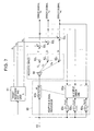
- Fig. 1 is a diagram illustrating of the configuration of a multipoint adaptive equalization control system according to an embodiment of the present invention.
- the system is configured to perform adaptive signal processing in the frequency domain, the system may be configured to perform adaptive signal processing in the time domain.
- sound waves in a main control point and other (first to Kth) control points are controlled.
- suffix M indicates the main control point and suffixes S1 to SK denote the first to Kth control points, respectively.
- a fast Fourier transform (FFT) unit 1 converts an audio signal x(t) into an audio signal X(f) in the frequency domain and supplies the signal to each of a target response setting unit 2 and an adaptive signal processor 8.
- a target response characteristic (impulse response) H is set in the target response setting unit 2.
- the target response setting unit 2 receives the audio signal X(f) and outputs target response signals d M (f), d S1 (f), ..., and d SK (f), which correspond to the audio signal X(f), for the respective control points so as to supply the target response signals to absolute value calculating units 3 M , 3 S1 , ..., and 3 SK , respectively.
- the absolute value calculating units 3 M , 3 S1 , ..., and 3 SK calculate absolute values D M (f), D S1 (f), ..., and D SK (f) of the supplied target response signals d M (f), d S1 (f), ..., and d SK (f) and supply the absolute values D M (f), D S1 (f), ..., and D SK (f) of the target response signals to calculating units 4 M , 4 S1 , ..., and 4 SK , respectively.
- Microphones 5 M , 5 S1 , ..., and 5 SK are arranged in respective listening positions (the main control point and the first to Kth control points) in a car cabin as an acoustic space.
- the microphones 5 M , 5 S1 , ..., and 5 SK detect sound in the control points and supply detection sound signals, each corresponding to the detected sound, to FFT units 6 M , 6 S1 , ..., and 6 SK , respectively.
- the FFT units 6 M ⁇ , 6 S1 , ..., and 6 SK convert the supplied sound signals into sound signals y M (f), y S1 (f), ..., and y SK (f) in the frequency domain and supply the converted signals to absolute value calculating units 7 M , 7 S1 , ..., and 7 SK , respectively.
- the absolute value calculating units 7 M , 7 S1 , ..., and 7 SK calculate absolute values Y M (f), Y S1 (f), ..., and Y SK (f) of the supplied sound signals y M (f), y S1 (f), ..., and y SK (f) and supply the absolute values Y M (f), Y S1 (f), ..., and Y SK (f) to the calculating units 4 M , 4 S1 , ..., and 4 SK , respectively.
- the calculating units 4 M , 4 S1 , ..., and 4 SK calculate the differences between the supplied absolute values D M (f), D S1 (f), ..., and D SK (f) of the target response signals and the absolute values Y M (f), Y S1 (f), ..., and Y SK (f) of the detection sound signals using the following equations to obtain error signals E M (f), E S1 (f), ..., and E SK (f) indicating the differences, respectively.
- E M f D M f - Y M f
- the adaptive signal processor 8 performs adaptive signal processing so that the sum of the powers of the error signals E M (f), E S1 (f), ..., and E SK (f) in the respective control points are minimized, thus determining a gain to be applied to the audio signal X(f).
- the adaptive signal processor 8 multiplies the audio signal X(f) by the gain to generate an audio signal X'(f) and supplies the generated signal to an inverse FFT (IFFT) unit 9.
- IFFT unit 9 converts the supplied signal X'(f) into a sound signal X'(t) in the time domain and supplies the signal to a speaker 10.
- the speaker 10 radiates sound based on the supplied sound signal X'(t) to the car cabin as the acoustic space.
- the target response characteristic H set in the target response setting unit 2 is a characteristic for a sound field space intended to be reproduced.
- the set characteristic is a characteristic that has a delay time t/2 and is flat over an entire range of audio frequencies (a characteristic having a gain of 1).
- the target response setting unit 2 having such a target response characteristic can be realized by setting the coefficient of a tap corresponding to the delay time t/2 of an FIR digital filter to 1 and setting the coefficients of the other taps to 0.
- the target response characteristic can be common to the control points. Alternatively, the target response characteristic may differ from control point to control point.
- the adaptive signal processor 8 receives the audio signal X(f), performs the adaptive signal processing so that the sum of the powers of the error signals E M (f), E S1 (f), ..., and E SK (f) output from the above-described calculating units 4 M , 4 S1 , ..., and 4 SK , is minimized, and outputs the audio signal X'(f).
- the adaptive signal processor 8 includes an LMS unit 8a, a gain setting unit 8b, signal processing filters 8c M , 8c S1 , ..., and 8c SK , absolute value calculating units 8d M , 8d S1 , ..., and 8d SK , and an inverse phase characteristic (IPC) setting unit 8e.
- the LMS unit 8a performs calculation based on an LMS adaptive signal algorithm.
- the gain setting unit 8b sets a gain.
- the absolute value calculating units 8d M , 8d S1 , ..., and 8d SK calculate absolute values of the supplied reference signals, respectively.
- the IPC setting unit 8e constitutes an adaptive filter.
- the adaptive signal processor 8 controls only the gain so that the sum of the powers of the respective error signals is minimized and does not control any phase.
- An inverse phase IPC M (f) of a phase characteristic from the speaker 10 to the main control point is set in the IPC setting unit 8e.
- the IPC setting unit 8e controls the phase of the audio signal and supplies the resultant signal to the gain setting unit 8b. Specifically, the IPC setting unit 8e sets an inverse phase characteristic so that a phase delay of the audio signal is 0 in the main control point.
- the IPC setting unit 8e and the gain setting unit 8b constitute the adaptive filter.
- G(n, f) indicates a gain before one sampling
- ⁇ M (f), ⁇ S1 (f), ..., and ⁇ SK (f) denote parameters for adjusting the amount of update of a filter coefficient
- f includes f 1 , f 2 , ..., and f N/2 .
- the gain setting unit 8b multiplies the audio signal output from the IPC setting unit 8e by the gain G(n+1, f) determined by the LMS unit 8a and supplies the resultant signal to the IFFT unit 9.
- W(f) denotes a compensated filter coefficient for adaptive signal processing
- the coefficient W(f) is given by the following equation on the condition that an initial characteristic of G(f) is 0 at each of the frequencies f 1 , f 2 , ..., f N/2 .
- W f G f * IPC M f
- the phase of the compensated filter coefficient W(f) is fixed by the inverse phase IPC M (f) and only the gain is subjected to adaptive control so that the sum of the powers of the error signals in the respective control points is minimized.
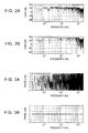
- Figs. 2A to 5B are diagrams illustrating the comparisons between the measurements of gain characteristics and phase characteristics of sound signals in the use of a related-art multipoint adaptive equalization control system and those in the use of the multipoint adaptive equalization control system according to the embodiment of the present invention.
- Figs. 2A and 2B each illustrate a gain characteristic in the main control point.
- Figs. 3A and 3B each illustrate a phase characteristic in the main control point.
- Figs. 4A and 4B each illustrate a gain characteristic in a control point other than the main control point.
- Figs. 5A and 5B each illustrate a phase characteristic in a control point other than the main control point.
- FIG. 2A, 3A , 4A, and 5A illustrate the measurements in the use of the related-art multipoint adaptive equalization control system ( Fig. 7 ).
- Figs. 2B , 3B , 4B, and 5B illustrate the measurements in the use of the multipoint adaptive equalization control system according to the embodiment of the present invention.
- the gain fluctuates over the range of frequencies.
- the gain is substantially flat over the range of frequencies.
- the phase characteristic varies.
- the gain characteristic in the multipoint adaptive equalization control system according to the embodiment of the present invention over the range of frequencies is flatter than that in the related-art system.
- the multipoint adaptive equalization control system according to the embodiment of the present invention provides the phase characteristic as well as that in the related-art system, though phase compensation is not performed over the range of frequencies in the system according to the embodiment of the present invention.
- the IPC setting unit 8e is placed before the gain setting unit 8b.
- the IPC setting unit 8e may be disposed after the gain setting unit 8b.
- characteristics as well as those in the related art can be obtained in the control points other than the main control point.
- the embodiment of the present invention needs only one speaker and only one adaptive signal processor. Accordingly, the configuration of the system can be simplified. According to the embodiment of the present invention, only the gain can be determined using the adaptive signal algorithm. Thus, adaptive signal processing can be performed at high speed.
Landscapes
- Physics & Mathematics (AREA)
- Engineering & Computer Science (AREA)
- Acoustics & Sound (AREA)
- Signal Processing (AREA)
- Circuit For Audible Band Transducer (AREA)
- Soundproofing, Sound Blocking, And Sound Damping (AREA)
- Fittings On The Vehicle Exterior For Carrying Loads, And Devices For Holding Or Mounting Articles (AREA)
- Cable Transmission Systems, Equalization Of Radio And Reduction Of Echo (AREA)
Abstract
Description
- The present invention relates to a method and system for multipoint adaptive equalization control, and in particular, to a multipoint adaptive equalization method and system for performing adaptive equalization control on sound detected at a plurality of control points in a car cabin.
- In a typical acoustic space, reflected waves and standing waves are caused by walls and sound waves mutually interfere, which complicates and disturbs an acoustic transmission characteristic. Particularly, in a small space, such as a car cabin, surrounded by things that easily reflect sound, for example, glass, the influence of reflected waves and standing waves is large. Accordingly, the disturbance of the acoustic transmission characteristic seriously affects the hearing of sound in such a small space. As a technique of compensating the disturbance of the acoustic transmission characteristic, an adaptive equalization control system has been known. The adaptive equalization control system can produce a predetermined sound field space at any control point.
-
Fig. 6 is a block diagram of an adaptive equalization control system to be applied to an audio system, the control system being disclosed in Japanese Unexamined Patent Application Publication No.11-167383 response setting unit 61. The targetresponse setting unit 61 receives the audio signal x(n) output from the audio source and outputs a target response signal d(n) corresponding to the received signal. Amicrophone 62 is placed in a listening position (control point) in a car cabin as an acoustic space. Themicrophone 62 detects sound in this control point and outputs a music signal y(n). A calculatingunit 63 calculates the difference between the music signal y(n) output from themicrophone 62 and the target response signal d(n) output from the targetresponse setting unit 61 and outputs an error signal e(n) indicating the difference. Anadaptive signal processor 60 generates a signal x'(n) so that the power of the error signal e(n) is minimized. Aspeaker 64 radiates sound based on the signal x'(n) output from theadaptive signal processor 60 to the car cabin as the acoustic space. - The target response characteristic h set in the target
response setting unit 61 is a characteristic for a sound field space intended to be reproduced. For example, when let t denote a delay time corresponding to approximately half the number of taps of an adaptive filter, the set characteristic is a characteristic that has the delay time t and is flat over an entire range of audio frequencies (a characteristic having a gain of 1). The delay time t is used for accurate approximation of the inverse characteristic of an acoustic space through the adaptive filter. The targetresponse setting unit 61 having such a target response characteristic can be realized by setting the coefficient of a tap, corresponding to the delay time t, in a finite impulse response (FIR) digital filter to 1 and setting the coefficients of the other taps to 0. - The
adaptive signal processor 60 receives the audio signal x(n) and also receives the error signal e(n) output from the above-described calculatingunit 63. Theadaptive signal processor 60 performs adaptive signal processing so that the power of the error signal e(n) is minimized to output the signal x'(n). Theadaptive signal processor 60 includes a least mean square (LMS)unit 60a, anFIR filter 60b which serves as an adaptive filter, and asignal processing filter 60c that convolves a propagation characteristic (transmission characteristic) C of an acoustic propagation path from thespeaker 64 to the control point (the microphone 62) with the audio signal x(n) to generate a reference signal for adaptive signal processing. - The
LMS unit 60a receives the error signal e(n) in the control point and the reference signal output from thesignal processing filter 60c. When let W(n) denote a filter coefficient of an FIR filter at time n, theLMS unit 60a sets the filter coefficient of theFIR filter 60b at time (n+1) using the above-described signals, the LMS algorithm, and the following equation so that the signal x'(n) at the control point is equivalent to the target response signal d(n) :
TheFIR filter 60b performs digital filtering on an audio signal x(n+1) using the set filter coefficient to output a signal x'(n+1). - The above-described adaptive processing allows the filter coefficient of the
FIR filter 60b to converge so that the power of the error signal e(n) is minimized, thus allowing listening to music similar to that in a space having the target response characteristic h set in the targetresponse setting unit 61. - In the above-described adaptive equalization control system, music can be listened at the control point with a transmission characteristic similar to the target response characteristic h. However, the system does not assure the characteristic at points other than the control point. To achieve ideal listening to music at many positions in an acoustic space through the adaptive equalization control system, many control points have to be set and many speakers and microphones are accordingly needed. In other words, a multipoint adaptive equalization system requires many speakers which serve as control audio sources and many microphones. Accordingly, the number of adaptive filters (FIR filters) is increased. Disadvantageously, it may result in an increase in circuit scale and an increase in the amount of calculation.
- Hence, there has been proposed a multipoint adaptive equalization control system capable of compensating a transmission characteristic over an entire acoustic space using fewer speakers and fewer adaptive filters.
Fig. 7 is a diagram illustrating the configuration of such a multipoint adaptive equalization control system. In this system, one speaker and one adaptive filter are arranged and microphones are placed at respective control points for multipoint adaptive equalization control. The system inFig. 7 differs from the system inFig. 6 in the following points: (1)microphones 621 to 62K are arranged at many (= K) control points, respectively; (2) a target response characteristic for the respective control points is set in the targetresponse setting unit 61; (3) calculatingunits 631 to 63K are placed so as to calculate the differences between sound signals y1 to yK detected at the respective control points and target response signals d1 to dK and output error signals e1 to eK, respectively; and (4) theadaptive signal processor 60 updates the filter coefficient of theFIR filter 60b using the following equation so that the sum of the powers of the error signals are minimized and sets the updated filter coefficient in the filter.
In theadaptive signal processor 60, measurement transmission characteristics from the speaker to the respective control points are set insignal processing filters 60c1 to 60cK, respectively. Consequently, sound signals detected at the K control points can realize characteristics approximate to those of a desired signal. - In the above-described related art, however, the system operates so as to yield characteristics in which errors of sound signals at all control points are reduced on average. Regarding the characteristics of a sound signal at each of the control points, the characteristics are deteriorated as compared to the ideal characteristics obtained using only one main control point in
Fig. 6 . Particularly, a frequency-phase characteristic indicating sound-wave arrival time at each frequency is subjected to average compensation in the control points, thus causing a feeling of strangeness in hearing. - Accordingly, it is an object of the present invention to remove a feeling of strangeness in hearing at a main control point even when compensation is performed in a plurality of control points, particularly when using one speaker and one adaptive signal processor. Further, it would be beneficial to achieve the improvement of characteristics in the other control points excluding the main control point.
- According to aspects of the present invention, there are provided a multipoint adaptive equalization control method and system for performing adaptive equalization control on sound detected at a plurality of control points in a car cabin.
- According to an aspect of the present invention, a multipoint adaptive equalization control method includes applying an inverse phase characteristic to an audio signal output from an audio source, the inverse phase characteristic being opposite to a phase characteristic from a speaker to a main control point, outputting sound based on an input audio signal with the applied inverse phase characteristic from the speaker to an acoustic space, outputting error signals indicating the differences between detection signals, corresponding to the detected sound output from the speaker, in the respective control points and target signals for the control points, receiving the error signals in the respective control points and performing adaptive signal processing so that the sum of powers of the error signals is minimized to determine a gain of an audio signal, and applying the inverse phase characteristic and the gain to an audio signal and supplying the resultant audio signal to the speaker.
- According to another aspect of the present invention, a multipoint adaptive equalization control system includes a filter that has an inverse phase characteristic opposite to a phase characteristic to a main control point, a speaker that outputs sound based on an audio signal supplied through the filter, error signal generating units that output error signals indicating the differences between detection signals, corresponding to detected the sound output from the speaker, in the respective control points and target signals for the control points, respectively, an adaptive signal processing unit that receives the error signals in the respective control points and performs adaptive signal processing so that the sum of powers of the error signals is minimized to determine a gain of an audio signal, and a gain setting unit placed before or after the filter, the gain setting unit multiplying an audio signal by the gain and supplying the resultant audio signal to the speaker.
- According to aspects of the present invention, an inverse phase characteristic opposite to a phase characteristic from a speaker to a main control point is applied to an audio signal output from an audio source. Sound based on an input audio signal with the applied inverse phase characteristic is output from the speaker to an acoustic space. Error signals, related to sound output from the speaker, in respective control points are received and adaptive signal processing is performed so that the sum of powers of the error signals is minimized, thus determining a gain of an audio signal. The inverse phase characteristic and the gain are applied to an audio signal and the resultant signal is supplied to the speaker. Accordingly, when a sound signal is compensated in a plurality of control points using one speaker and one adaptive signal processor, a feeling of strangeness in hearing at a main control point can be removed. In addition, characteristics can be improved in the other control points excluding the main control point.
-
-
Fig. 1 is a diagram of the configuration of a multipoint adaptive equalization control system according to an embodiment of the present invention; -
Figs. 2A and 2B illustrate a gain characteristic obtained at a main control point in a related-art system and that in the system according to the embodiment, respectively; -
Figs. 3A and 3B illustrate a phase characteristic obtained at the main control point in the related-art system and that in the system according to the embodiment, respectively; -
Figs. 4A and 4B illustrate a gain characteristic obtained at a control point other than the main control point in the related-art system and that in the system according to the embodiment, respectively; -
Figs. 5A and 5B illustrate a phase characteristic obtained at a control point other than the main control point in the related-art system and that in the system according to the embodiment, respectively; -
Fig. 6 is a block diagram of a first related-art adaptive equalization control system to be applied to an audio system; and -
Fig. 7 is a diagram of the configuration of a related-art multipoint adaptive equalization control system. - An embodiment of the present invention proposes an algorithm for compensating a frequency-phase characteristic indicating sound-wave arrival time at each frequency in only one main control point and compensating a gain characteristic in each of control points. Accordingly, the phase characteristic is compensated in only the main control point while the gain characteristic is being compensated in all the control points, so that the control performance in the main control point can be increased and the gain characteristic can be compensated in the other control points.
-
Fig. 1 is a diagram illustrating of the configuration of a multipoint adaptive equalization control system according to an embodiment of the present invention. Although the system is configured to perform adaptive signal processing in the frequency domain, the system may be configured to perform adaptive signal processing in the time domain. In the system, it is assumed that sound waves in a main control point and other (first to Kth) control points are controlled. InFig. 1 , suffix M indicates the main control point and suffixes S1 to SK denote the first to Kth control points, respectively. - A fast Fourier transform (FFT)
unit 1 converts an audio signal x(t) into an audio signal X(f) in the frequency domain and supplies the signal to each of a targetresponse setting unit 2 and an adaptive signal processor 8. A target response characteristic (impulse response) H is set in the targetresponse setting unit 2. The targetresponse setting unit 2 receives the audio signal X(f) and outputs target response signals dM(f), dS1(f), ..., and dSK(f), which correspond to the audio signal X(f), for the respective control points so as to supply the target response signals to absolutevalue calculating units - The absolute
value calculating units - The FFT units 6M\, 6S1, ..., and 6SK convert the supplied sound signals into sound signals yM(f), yS1(f), ..., and ySK(f) in the frequency domain and supply the converted signals to absolute value calculating units 7M, 7S1, ..., and 7SK, respectively. The absolute value calculating units 7M, 7S1, ..., and 7SK calculate absolute values YM(f), YS1(f), ..., and YSK(f) of the supplied sound signals yM(f), yS1(f), ..., and ySK(f) and supply the absolute values YM(f), YS1(f), ..., and YSK(f) to the calculating units 4M, 4S1, ..., and 4SK, respectively.
- The calculating units 4M, 4S1, ..., and 4SK calculate the differences between the supplied absolute values DM(f), DS1(f), ..., and DSK(f) of the target response signals and the absolute values YM(f), YS1(f), ..., and YSK(f) of the detection sound signals using the following equations to obtain error signals EM(f), ES1(f), ..., and ESK(f) indicating the differences, respectively.

- The adaptive signal processor 8 performs adaptive signal processing so that the sum of the powers of the error signals EM(f), ES1(f), ..., and ESK(f) in the respective control points are minimized, thus determining a gain to be applied to the audio signal X(f). The adaptive signal processor 8 multiplies the audio signal X(f) by the gain to generate an audio signal X'(f) and supplies the generated signal to an inverse FFT (IFFT)
unit 9. TheIFFT unit 9 converts the supplied signal X'(f) into a sound signal X'(t) in the time domain and supplies the signal to aspeaker 10. Thespeaker 10 radiates sound based on the supplied sound signal X'(t) to the car cabin as the acoustic space. - The target response characteristic H set in the target
response setting unit 2 is a characteristic for a sound field space intended to be reproduced. For example, when let t denote a delay time from the speaker to the main control point, the set characteristic is a characteristic that has a delay time t/2 and is flat over an entire range of audio frequencies (a characteristic having a gain of 1). The targetresponse setting unit 2 having such a target response characteristic can be realized by setting the coefficient of a tap corresponding to the delay time t/2 of an FIR digital filter to 1 and setting the coefficients of the other taps to 0. The target response characteristic can be common to the control points. Alternatively, the target response characteristic may differ from control point to control point. - The adaptive signal processor 8 receives the audio signal X(f), performs the adaptive signal processing so that the sum of the powers of the error signals EM(f), ES1(f), ..., and ESK(f) output from the above-described calculating units 4M, 4S1, ..., and 4SK, is minimized, and outputs the audio signal X'(f).
- The adaptive signal processor 8 includes an
LMS unit 8a, again setting unit 8b, signal processing filters 8cM, 8cS1, ..., and 8cSK, absolute value calculating units 8dM, 8dS1, ..., and 8dSK, and an inverse phase characteristic (IPC)setting unit 8e. TheLMS unit 8a performs calculation based on an LMS adaptive signal algorithm. Thegain setting unit 8b sets a gain. The signal processing filters 8cM, 8cS1, ... , and 8cSK convolve transmission characteristics C^M, C^S1, ..., and C^SK of acoustic propagation paths from thespeaker 10 to the respective microphones (control points) 5M, 5S1, ..., and 5SK with the audio signal X(f) to generate reference signals, respectively. The absolute value calculating units 8dM, 8dS1, ..., and 8dSK calculate absolute values of the supplied reference signals, respectively. TheIPC setting unit 8e constitutes an adaptive filter. The adaptive signal processor 8 controls only the gain so that the sum of the powers of the respective error signals is minimized and does not control any phase. - An inverse phase IPCM(f) of a phase characteristic from the
speaker 10 to the main control point is set in theIPC setting unit 8e. TheIPC setting unit 8e controls the phase of the audio signal and supplies the resultant signal to thegain setting unit 8b. Specifically, theIPC setting unit 8e sets an inverse phase characteristic so that a phase delay of the audio signal is 0 in the main control point. TheIPC setting unit 8e and thegain setting unit 8b constitute the adaptive filter. In this case, the inverse phase IPCM(f) is determined using the following equation.
where * denotes a complex conjugate, |·| indicates an absolute value, and CM(f) denotes a transmission characteristic from the speaker to the main control point. - The
LMS unit 8a receives the error signals EM(f), ES1(f), ..., and ESK(f) in the respective control points and the reference signals output from the absolute value calculating units 8dM, 8dS1, ..., and 8dSK and determines a gain G(n+1, f) for thegain setting unit 8b using the following equation:
where G(n, f) indicates a gain before one sampling, µM(f), µS1(f), ..., and µSK(f) denote parameters for adjusting the amount of update of a filter coefficient, and EM(f), ES1(f), ..., and ESK(f) denote errors in the respective control points relative to the target response. Assuming that the size of FFT is N, f includes f1, f2, ..., and fN/2. Thegain setting unit 8b multiplies the audio signal output from theIPC setting unit 8e by the gain G(n+1, f) determined by theLMS unit 8a and supplies the resultant signal to theIFFT unit 9. - When W(f) denotes a compensated filter coefficient for adaptive signal processing, the coefficient W(f) is given by the following equation on the condition that an initial characteristic of G(f) is 0 at each of the frequencies f1, f2, ..., fN/2.

Specifically, the phase of the compensated filter coefficient W(f) is fixed by the inverse phase IPCM(f) and only the gain is subjected to adaptive control so that the sum of the powers of the error signals in the respective control points is minimized. -
Figs. 2A to 5B are diagrams illustrating the comparisons between the measurements of gain characteristics and phase characteristics of sound signals in the use of a related-art multipoint adaptive equalization control system and those in the use of the multipoint adaptive equalization control system according to the embodiment of the present invention.Figs. 2A and 2B each illustrate a gain characteristic in the main control point.Figs. 3A and 3B each illustrate a phase characteristic in the main control point.Figs. 4A and 4B each illustrate a gain characteristic in a control point other than the main control point.Figs. 5A and 5B each illustrate a phase characteristic in a control point other than the main control point.Figs. 2A, 3A ,4A, and 5A illustrate the measurements in the use of the related-art multipoint adaptive equalization control system (Fig. 7 ).Figs. 2B ,3B ,4B, and 5B illustrate the measurements in the use of the multipoint adaptive equalization control system according to the embodiment of the present invention. - In
Fig. 2A regarding the related art, the gain fluctuates over the range of frequencies. Whereas, inFig. 2B regarding the embodiment of the present invention, the gain is substantially flat over the range of frequencies. Referring toFig. 3A regarding the related art, the phase characteristic varies. Whereas, inFig. 3B regarding the embodiment, the phase characteristic is 0 over the range of frequencies. Since the phase characteristic representing arrival times of signals at respective frequencies in the control point indicates a constant value (= 0), any signal delay does not occur at a desired control point. - Referring to
Figs. 4A and 4B , the gain characteristic in the multipoint adaptive equalization control system according to the embodiment of the present invention over the range of frequencies is flatter than that in the related-art system. Referring toFigs. 5A and 5B , the multipoint adaptive equalization control system according to the embodiment of the present invention provides the phase characteristic as well as that in the related-art system, though phase compensation is not performed over the range of frequencies in the system according to the embodiment of the present invention. In the embodiment, theIPC setting unit 8e is placed before thegain setting unit 8b. TheIPC setting unit 8e may be disposed after thegain setting unit 8b. - In the related art, since average compensation is performed in a plurality of control points, characteristics in all the control points are compensated to an acceptable extent, thus leaving a feeling of strangeness in hearing. According to the embodiment, both of the gain characteristic and phase characteristic over the range of frequencies of sound signals are compensated in a desired control point of a plurality of control points. Only the gain characteristic is compensated in the other control points. Accordingly, the phase characteristic at a constant value (= 0) can be obtained in the desired control point, thus removing a feeling of strangeness in hearing. In addition, characteristics as well as those in the related art can be obtained in the control points other than the main control point.
- The embodiment of the present invention needs only one speaker and only one adaptive signal processor. Accordingly, the configuration of the system can be simplified. According to the embodiment of the present invention, only the gain can be determined using the adaptive signal algorithm. Thus, adaptive signal processing can be performed at high speed.
Claims (11)
- A multipoint adaptive equalization control method for performing adaptive equalization control on sound detected at a plurality of control points in a room, comprising:applying an inverse phase characteristic to an audio signal (X(f))output from an audio source, the inverse phase characteristic being opposite to a phase characteristic from a speaker (10) to a main control point;outputting sound based on an input audio signal (X(f)) with the applied inverse phase characteristic from the speaker (10) to an acoustic space;outputting error signals (EM, ES1, ESK) respectively indicating the differences between detection signals, corresponding to the detected sound output from the speaker, in the respective control points and target signals for the control points;receiving the error signals in the respective control points and performing adaptive signal processing so that the sum of powers of the error signals is minimized to determine a gain (G) of an audio signal; andapplying the inverse phase characteristic and the gain to an audio signal (X(f)) and supplying the resultant audio signal to the speaker.
- The method according to Claim 1, further comprising:setting a target response characteristic (H) for output of the target signals for the respective control points and outputting the target signals for the control points when an audio signal is input.
- The method according to Claim 1 or 2, wherein the adaptive signal processing is performed in the frequency domain.
- The method according to any one of Claims 1, 2, and 3, wherein the adaptive signal processing is calculation based on a least mean square adaptive signal algorithm.
- The method according to any one of Claims 1, 2, 3, and 4, wherein the room is a car cabin.
- A multipoint adaptive equalization control system for performing adaptive equalization control on sound detected at a plurality of control points in a room, comprising:a filter (8e) that has an inverse phase characteristic opposite to a phase characteristic to a main control point;a speaker (10) that outputs sound based on an audio signal supplied through the filter;error signal generating units (4M, 4S1, ..., and 4SK) that output error signals indicating the differences between detection signals, corresponding to the detected sound output from the speaker (10), in the respective control points and target signals for the control points, respectively;an adaptive signal processing unit (8a) that receives the error signals in the respective control points and performs adaptive signal processing so that the sum of powers of the error signals is minimized to determine a gain of an audio signal; anda gain setting unit (8b) placed before or after the filter, the gain setting unit multiplying an audio signal by the gain and supplying the resultant audio signal to the speaker (10).
- The system according to Claim 6, further comprising:a target response setting unit (2) that has a set target response characteristic for output of the target signals for the respective control points and outputs the target signals for the control points when receiving an audio signal.
- The system according to Claim 6 or 7, further comprising:fast Fourier transform units (1, 6M, 6S1, ..., 6SK) that convert signals to be supplied to the adaptive signal processing unit (8a) into signals in the frequency domain.
- The system according to any one of Claims 6, 7, and 8, wherein the adaptive signal processing unit (8a) includes a least mean square unit (8a) that performs calculation based on a least mean square adaptive signal algorithm.
- The system according to any one of Claims 6, 7, 8, and 9, further comprising:signal processing filters (8cM, 8cS1, ..., 8cSK) that convolve transmission characteristics of acoustic propagation paths from the speaker to the respective control points with an audio signal to generate reference signals, respectively.
- The system according to any one of Claims 6, 7, 8, 9, and 10, wherein the room is a car cabin.
Applications Claiming Priority (1)
| Application Number | Priority Date | Filing Date | Title |
|---|---|---|---|
| JP2009116674A JP5430220B2 (en) | 2009-05-13 | 2009-05-13 | Multipoint adaptive equalization control method and multipoint adaptive equalization control system |
Publications (3)
| Publication Number | Publication Date |
|---|---|
| EP2257084A2 true EP2257084A2 (en) | 2010-12-01 |
| EP2257084A3 EP2257084A3 (en) | 2013-11-13 |
| EP2257084B1 EP2257084B1 (en) | 2018-12-05 |
Family
ID=42938508
Family Applications (1)
| Application Number | Title | Priority Date | Filing Date |
|---|---|---|---|
| EP10162704.0A Active EP2257084B1 (en) | 2009-05-13 | 2010-05-12 | Multipoint adaptive equalization control method and multipoint adaptive equalization control system |
Country Status (2)
| Country | Link |
|---|---|
| EP (1) | EP2257084B1 (en) |
| JP (1) | JP5430220B2 (en) |
Cited By (1)
| Publication number | Priority date | Publication date | Assignee | Title |
|---|---|---|---|---|
| WO2024161074A1 (en) * | 2023-02-02 | 2024-08-08 | L-Acoustics | Method and device for obtaining a filter for a digital audio signal, and method and device using this filter |
Citations (1)
| Publication number | Priority date | Publication date | Assignee | Title |
|---|---|---|---|---|
| JPH11167383A (en) | 1997-12-03 | 1999-06-22 | Alpine Electron Inc | Method for checking connection of adaptive equalization system |
Family Cites Families (5)
| Publication number | Priority date | Publication date | Assignee | Title |
|---|---|---|---|---|
| JP2530475B2 (en) * | 1988-03-29 | 1996-09-04 | ティーオーエー株式会社 | Frequency characteristic equalizer for loudspeaker system |
| JP3421146B2 (en) * | 1994-10-28 | 2003-06-30 | アルパイン株式会社 | Sound field control method and device |
| JP3539855B2 (en) * | 1997-12-03 | 2004-07-07 | アルパイン株式会社 | Sound field control device |
| US7567675B2 (en) * | 2002-06-21 | 2009-07-28 | Audyssey Laboratories, Inc. | System and method for automatic multiple listener room acoustic correction with low filter orders |
| EP1986466B1 (en) * | 2007-04-25 | 2018-08-08 | Harman Becker Automotive Systems GmbH | Sound tuning method and apparatus |
-
2009
- 2009-05-13 JP JP2009116674A patent/JP5430220B2/en active Active
-
2010
- 2010-05-12 EP EP10162704.0A patent/EP2257084B1/en active Active
Patent Citations (1)
| Publication number | Priority date | Publication date | Assignee | Title |
|---|---|---|---|---|
| JPH11167383A (en) | 1997-12-03 | 1999-06-22 | Alpine Electron Inc | Method for checking connection of adaptive equalization system |
Cited By (1)
| Publication number | Priority date | Publication date | Assignee | Title |
|---|---|---|---|---|
| WO2024161074A1 (en) * | 2023-02-02 | 2024-08-08 | L-Acoustics | Method and device for obtaining a filter for a digital audio signal, and method and device using this filter |
Also Published As
| Publication number | Publication date |
|---|---|
| JP5430220B2 (en) | 2014-02-26 |
| JP2010266599A (en) | 2010-11-25 |
| EP2257084B1 (en) | 2018-12-05 |
| EP2257084A3 (en) | 2013-11-13 |
Similar Documents
| Publication | Publication Date | Title |
|---|---|---|
| EP2043383B1 (en) | Active noise control using bass management | |
| EP3669780B1 (en) | Methods, devices and system for a compensated hearing test | |
| US10540954B2 (en) | Calibration and stabilization of an active noise cancelation system | |
| US8942976B2 (en) | Method and device for noise reduction control using microphone array | |
| EP1804549B1 (en) | Signal processing system and method for calibrating channel signals supplied from an array of sensors having different operating characteristics | |
| KR101597752B1 (en) | Apparatus and method for noise estimation and noise reduction apparatus employing the same | |
| US9269343B2 (en) | Method of controlling an update algorithm of an adaptive feedback estimation system and a decorrelation unit | |
| US20130129100A1 (en) | Processing audio signals | |
| EP1538868B1 (en) | Audio amplification apparatus | |
| JP6870078B2 (en) | Noise estimation for dynamic sound adjustment | |
| CN111866662B (en) | Adjusting method for active noise reduction and related circuit | |
| US7995774B2 (en) | Sound field control apparatus and sound field control method | |
| JP2008283600A (en) | Automatic sound field correction device | |
| EP2257084B1 (en) | Multipoint adaptive equalization control method and multipoint adaptive equalization control system | |
| EP4362008A1 (en) | System and method for estimating secondary path impulse response for active noise cancellation | |
| CN115529532B (en) | Method for directional signal processing of signals of a microphone arrangement | |
| JP5883580B2 (en) | Filter coefficient determination device | |
| JP4522509B2 (en) | Audio equipment | |
| WO2023214571A1 (en) | Beamforming method and beamforming system | |
| JPWO2009008068A1 (en) | Automatic sound field correction device | |
| JPH10284965A (en) | Control band decision method for audio equipment | |
| JP7020955B2 (en) | Sound field correction device, sound field correction method and sound field correction program | |
| Brännmark et al. | Controlling the impulse responses and the spatial variability in digital loudspeaker-room correction | |
| EP2963950A1 (en) | Modal response compensation |
Legal Events
| Date | Code | Title | Description |
|---|---|---|---|
| PUAI | Public reference made under article 153(3) epc to a published international application that has entered the european phase |
Free format text: ORIGINAL CODE: 0009012 |
|
| AK | Designated contracting states |
Kind code of ref document: A2 Designated state(s): AL AT BE BG CH CY CZ DE DK EE ES FI FR GB GR HR HU IE IS IT LI LT LU LV MC MK MT NL NO PL PT RO SE SI SK SM TR |
|
| AX | Request for extension of the european patent |
Extension state: BA ME RS |
|
| PUAL | Search report despatched |
Free format text: ORIGINAL CODE: 0009013 |
|
| AK | Designated contracting states |
Kind code of ref document: A3 Designated state(s): AL AT BE BG CH CY CZ DE DK EE ES FI FR GB GR HR HU IE IS IT LI LT LU LV MC MK MT NL NO PL PT RO SE SI SK SM TR |
|
| AX | Request for extension of the european patent |
Extension state: BA ME RS |
|
| RIC1 | Information provided on ipc code assigned before grant |
Ipc: H04S 7/00 20060101AFI20131009BHEP |
|
| 17P | Request for examination filed |
Effective date: 20140424 |
|
| RBV | Designated contracting states (corrected) |
Designated state(s): AL AT BE BG CH CY CZ DE DK EE ES FI FR GB GR HR HU IE IS IT LI LT LU LV MC MK MT NL NO PL PT RO SE SI SK SM TR |
|
| GRAP | Despatch of communication of intention to grant a patent |
Free format text: ORIGINAL CODE: EPIDOSNIGR1 |
|
| STAA | Information on the status of an ep patent application or granted ep patent |
Free format text: STATUS: GRANT OF PATENT IS INTENDED |
|
| INTG | Intention to grant announced |
Effective date: 20180705 |
|
| GRAS | Grant fee paid |
Free format text: ORIGINAL CODE: EPIDOSNIGR3 |
|
| GRAA | (expected) grant |
Free format text: ORIGINAL CODE: 0009210 |
|
| GRAA | (expected) grant |
Free format text: ORIGINAL CODE: 0009210 |
|
| STAA | Information on the status of an ep patent application or granted ep patent |
Free format text: STATUS: THE PATENT HAS BEEN GRANTED |
|
| AK | Designated contracting states |
Kind code of ref document: B1 Designated state(s): AL AT BE BG CH CY CZ DE DK EE ES FI FR GB GR HR HU IE IS IT LI LT LU LV MC MK MT NL NO PL PT RO SE SI SK SM TR |
|
| REG | Reference to a national code |
Ref country code: GB Ref legal event code: FG4D |
|
| REG | Reference to a national code |
Ref country code: CH Ref legal event code: EP |
|
| REG | Reference to a national code |
Ref country code: AT Ref legal event code: REF Ref document number: 1074606 Country of ref document: AT Kind code of ref document: T Effective date: 20181215 |
|
| REG | Reference to a national code |
Ref country code: IE Ref legal event code: FG4D |
|
| REG | Reference to a national code |
Ref country code: DE Ref legal event code: R096 Ref document number: 602010055571 Country of ref document: DE |
|
| REG | Reference to a national code |
Ref country code: NL Ref legal event code: MP Effective date: 20181205 |
|
| REG | Reference to a national code |
Ref country code: AT Ref legal event code: MK05 Ref document number: 1074606 Country of ref document: AT Kind code of ref document: T Effective date: 20181205 |
|
| REG | Reference to a national code |
Ref country code: LT Ref legal event code: MG4D |
|
| PG25 | Lapsed in a contracting state [announced via postgrant information from national office to epo] |
Ref country code: LV Free format text: LAPSE BECAUSE OF FAILURE TO SUBMIT A TRANSLATION OF THE DESCRIPTION OR TO PAY THE FEE WITHIN THE PRESCRIBED TIME-LIMIT Effective date: 20181205 Ref country code: ES Free format text: LAPSE BECAUSE OF FAILURE TO SUBMIT A TRANSLATION OF THE DESCRIPTION OR TO PAY THE FEE WITHIN THE PRESCRIBED TIME-LIMIT Effective date: 20181205 Ref country code: LT Free format text: LAPSE BECAUSE OF FAILURE TO SUBMIT A TRANSLATION OF THE DESCRIPTION OR TO PAY THE FEE WITHIN THE PRESCRIBED TIME-LIMIT Effective date: 20181205 Ref country code: BG Free format text: LAPSE BECAUSE OF FAILURE TO SUBMIT A TRANSLATION OF THE DESCRIPTION OR TO PAY THE FEE WITHIN THE PRESCRIBED TIME-LIMIT Effective date: 20190305 Ref country code: HR Free format text: LAPSE BECAUSE OF FAILURE TO SUBMIT A TRANSLATION OF THE DESCRIPTION OR TO PAY THE FEE WITHIN THE PRESCRIBED TIME-LIMIT Effective date: 20181205 Ref country code: FI Free format text: LAPSE BECAUSE OF FAILURE TO SUBMIT A TRANSLATION OF THE DESCRIPTION OR TO PAY THE FEE WITHIN THE PRESCRIBED TIME-LIMIT Effective date: 20181205 Ref country code: NO Free format text: LAPSE BECAUSE OF FAILURE TO SUBMIT A TRANSLATION OF THE DESCRIPTION OR TO PAY THE FEE WITHIN THE PRESCRIBED TIME-LIMIT Effective date: 20190305 Ref country code: AT Free format text: LAPSE BECAUSE OF FAILURE TO SUBMIT A TRANSLATION OF THE DESCRIPTION OR TO PAY THE FEE WITHIN THE PRESCRIBED TIME-LIMIT Effective date: 20181205 |
|
| PG25 | Lapsed in a contracting state [announced via postgrant information from national office to epo] |
Ref country code: GR Free format text: LAPSE BECAUSE OF FAILURE TO SUBMIT A TRANSLATION OF THE DESCRIPTION OR TO PAY THE FEE WITHIN THE PRESCRIBED TIME-LIMIT Effective date: 20190306 Ref country code: SE Free format text: LAPSE BECAUSE OF FAILURE TO SUBMIT A TRANSLATION OF THE DESCRIPTION OR TO PAY THE FEE WITHIN THE PRESCRIBED TIME-LIMIT Effective date: 20181205 Ref country code: AL Free format text: LAPSE BECAUSE OF FAILURE TO SUBMIT A TRANSLATION OF THE DESCRIPTION OR TO PAY THE FEE WITHIN THE PRESCRIBED TIME-LIMIT Effective date: 20181205 |
|
| PG25 | Lapsed in a contracting state [announced via postgrant information from national office to epo] |
Ref country code: NL Free format text: LAPSE BECAUSE OF FAILURE TO SUBMIT A TRANSLATION OF THE DESCRIPTION OR TO PAY THE FEE WITHIN THE PRESCRIBED TIME-LIMIT Effective date: 20181205 |
|
| PG25 | Lapsed in a contracting state [announced via postgrant information from national office to epo] |
Ref country code: PT Free format text: LAPSE BECAUSE OF FAILURE TO SUBMIT A TRANSLATION OF THE DESCRIPTION OR TO PAY THE FEE WITHIN THE PRESCRIBED TIME-LIMIT Effective date: 20190405 Ref country code: IT Free format text: LAPSE BECAUSE OF FAILURE TO SUBMIT A TRANSLATION OF THE DESCRIPTION OR TO PAY THE FEE WITHIN THE PRESCRIBED TIME-LIMIT Effective date: 20181205 Ref country code: CZ Free format text: LAPSE BECAUSE OF FAILURE TO SUBMIT A TRANSLATION OF THE DESCRIPTION OR TO PAY THE FEE WITHIN THE PRESCRIBED TIME-LIMIT Effective date: 20181205 Ref country code: PL Free format text: LAPSE BECAUSE OF FAILURE TO SUBMIT A TRANSLATION OF THE DESCRIPTION OR TO PAY THE FEE WITHIN THE PRESCRIBED TIME-LIMIT Effective date: 20181205 |
|
| PG25 | Lapsed in a contracting state [announced via postgrant information from national office to epo] |
Ref country code: RO Free format text: LAPSE BECAUSE OF FAILURE TO SUBMIT A TRANSLATION OF THE DESCRIPTION OR TO PAY THE FEE WITHIN THE PRESCRIBED TIME-LIMIT Effective date: 20181205 Ref country code: SK Free format text: LAPSE BECAUSE OF FAILURE TO SUBMIT A TRANSLATION OF THE DESCRIPTION OR TO PAY THE FEE WITHIN THE PRESCRIBED TIME-LIMIT Effective date: 20181205 Ref country code: SM Free format text: LAPSE BECAUSE OF FAILURE TO SUBMIT A TRANSLATION OF THE DESCRIPTION OR TO PAY THE FEE WITHIN THE PRESCRIBED TIME-LIMIT Effective date: 20181205 Ref country code: IS Free format text: LAPSE BECAUSE OF FAILURE TO SUBMIT A TRANSLATION OF THE DESCRIPTION OR TO PAY THE FEE WITHIN THE PRESCRIBED TIME-LIMIT Effective date: 20190405 Ref country code: EE Free format text: LAPSE BECAUSE OF FAILURE TO SUBMIT A TRANSLATION OF THE DESCRIPTION OR TO PAY THE FEE WITHIN THE PRESCRIBED TIME-LIMIT Effective date: 20181205 |
|
| REG | Reference to a national code |
Ref country code: DE Ref legal event code: R097 Ref document number: 602010055571 Country of ref document: DE |
|
| PLBE | No opposition filed within time limit |
Free format text: ORIGINAL CODE: 0009261 |
|
| STAA | Information on the status of an ep patent application or granted ep patent |
Free format text: STATUS: NO OPPOSITION FILED WITHIN TIME LIMIT |
|
| PG25 | Lapsed in a contracting state [announced via postgrant information from national office to epo] |
Ref country code: SI Free format text: LAPSE BECAUSE OF FAILURE TO SUBMIT A TRANSLATION OF THE DESCRIPTION OR TO PAY THE FEE WITHIN THE PRESCRIBED TIME-LIMIT Effective date: 20181205 Ref country code: DK Free format text: LAPSE BECAUSE OF FAILURE TO SUBMIT A TRANSLATION OF THE DESCRIPTION OR TO PAY THE FEE WITHIN THE PRESCRIBED TIME-LIMIT Effective date: 20181205 |
|
| 26N | No opposition filed |
Effective date: 20190906 |
|
| REG | Reference to a national code |
Ref country code: CH Ref legal event code: PL |
|
| GBPC | Gb: european patent ceased through non-payment of renewal fee |
Effective date: 20190512 |
|
| PG25 | Lapsed in a contracting state [announced via postgrant information from national office to epo] |
Ref country code: LI Free format text: LAPSE BECAUSE OF NON-PAYMENT OF DUE FEES Effective date: 20190531 Ref country code: MC Free format text: LAPSE BECAUSE OF FAILURE TO SUBMIT A TRANSLATION OF THE DESCRIPTION OR TO PAY THE FEE WITHIN THE PRESCRIBED TIME-LIMIT Effective date: 20181205 Ref country code: CH Free format text: LAPSE BECAUSE OF NON-PAYMENT OF DUE FEES Effective date: 20190531 |
|
| REG | Reference to a national code |
Ref country code: BE Ref legal event code: MM Effective date: 20190531 |
|
| PG25 | Lapsed in a contracting state [announced via postgrant information from national office to epo] |
Ref country code: LU Free format text: LAPSE BECAUSE OF NON-PAYMENT OF DUE FEES Effective date: 20190512 |
|
| PG25 | Lapsed in a contracting state [announced via postgrant information from national office to epo] |
Ref country code: TR Free format text: LAPSE BECAUSE OF FAILURE TO SUBMIT A TRANSLATION OF THE DESCRIPTION OR TO PAY THE FEE WITHIN THE PRESCRIBED TIME-LIMIT Effective date: 20181205 |
|
| PG25 | Lapsed in a contracting state [announced via postgrant information from national office to epo] |
Ref country code: GB Free format text: LAPSE BECAUSE OF NON-PAYMENT OF DUE FEES Effective date: 20190512 Ref country code: IE Free format text: LAPSE BECAUSE OF NON-PAYMENT OF DUE FEES Effective date: 20190512 |
|
| PG25 | Lapsed in a contracting state [announced via postgrant information from national office to epo] |
Ref country code: BE Free format text: LAPSE BECAUSE OF NON-PAYMENT OF DUE FEES Effective date: 20190531 |
|
| PG25 | Lapsed in a contracting state [announced via postgrant information from national office to epo] |
Ref country code: CY Free format text: LAPSE BECAUSE OF FAILURE TO SUBMIT A TRANSLATION OF THE DESCRIPTION OR TO PAY THE FEE WITHIN THE PRESCRIBED TIME-LIMIT Effective date: 20181205 |
|
| PG25 | Lapsed in a contracting state [announced via postgrant information from national office to epo] |
Ref country code: HU Free format text: LAPSE BECAUSE OF FAILURE TO SUBMIT A TRANSLATION OF THE DESCRIPTION OR TO PAY THE FEE WITHIN THE PRESCRIBED TIME-LIMIT; INVALID AB INITIO Effective date: 20100512 Ref country code: MT Free format text: LAPSE BECAUSE OF FAILURE TO SUBMIT A TRANSLATION OF THE DESCRIPTION OR TO PAY THE FEE WITHIN THE PRESCRIBED TIME-LIMIT Effective date: 20181205 |
|
| PG25 | Lapsed in a contracting state [announced via postgrant information from national office to epo] |
Ref country code: MK Free format text: LAPSE BECAUSE OF FAILURE TO SUBMIT A TRANSLATION OF THE DESCRIPTION OR TO PAY THE FEE WITHIN THE PRESCRIBED TIME-LIMIT Effective date: 20181205 |
|
| PGFP | Annual fee paid to national office [announced via postgrant information from national office to epo] |
Ref country code: DE Payment date: 20250521 Year of fee payment: 16 |
|
| PGFP | Annual fee paid to national office [announced via postgrant information from national office to epo] |
Ref country code: FR Payment date: 20250528 Year of fee payment: 16 |