EP2256758A1 - Permanent magnet and method for manufacturing the same - Google Patents
Permanent magnet and method for manufacturing the same Download PDFInfo
- Publication number
- EP2256758A1 EP2256758A1 EP09722877A EP09722877A EP2256758A1 EP 2256758 A1 EP2256758 A1 EP 2256758A1 EP 09722877 A EP09722877 A EP 09722877A EP 09722877 A EP09722877 A EP 09722877A EP 2256758 A1 EP2256758 A1 EP 2256758A1
- Authority
- EP
- European Patent Office
- Prior art keywords
- magnet
- permanent magnet
- sintering
- raw material
- green sheet
- Prior art date
- Legal status (The legal status is an assumption and is not a legal conclusion. Google has not performed a legal analysis and makes no representation as to the accuracy of the status listed.)
- Withdrawn
Links
Images


Classifications
-
- H—ELECTRICITY
- H01—ELECTRIC ELEMENTS
- H01F—MAGNETS; INDUCTANCES; TRANSFORMERS; SELECTION OF MATERIALS FOR THEIR MAGNETIC PROPERTIES
- H01F41/00—Apparatus or processes specially adapted for manufacturing or assembling magnets, inductances or transformers; Apparatus or processes specially adapted for manufacturing materials characterised by their magnetic properties
- H01F41/02—Apparatus or processes specially adapted for manufacturing or assembling magnets, inductances or transformers; Apparatus or processes specially adapted for manufacturing materials characterised by their magnetic properties for manufacturing cores, coils, or magnets
- H01F41/0253—Apparatus or processes specially adapted for manufacturing or assembling magnets, inductances or transformers; Apparatus or processes specially adapted for manufacturing materials characterised by their magnetic properties for manufacturing cores, coils, or magnets for manufacturing permanent magnets
- H01F41/0266—Moulding; Pressing
-
- H—ELECTRICITY
- H01—ELECTRIC ELEMENTS
- H01F—MAGNETS; INDUCTANCES; TRANSFORMERS; SELECTION OF MATERIALS FOR THEIR MAGNETIC PROPERTIES
- H01F1/00—Magnets or magnetic bodies characterised by the magnetic materials therefor; Selection of materials for their magnetic properties
- H01F1/01—Magnets or magnetic bodies characterised by the magnetic materials therefor; Selection of materials for their magnetic properties of inorganic materials
- H01F1/03—Magnets or magnetic bodies characterised by the magnetic materials therefor; Selection of materials for their magnetic properties of inorganic materials characterised by their coercivity
- H01F1/032—Magnets or magnetic bodies characterised by the magnetic materials therefor; Selection of materials for their magnetic properties of inorganic materials characterised by their coercivity of hard-magnetic materials
- H01F1/04—Magnets or magnetic bodies characterised by the magnetic materials therefor; Selection of materials for their magnetic properties of inorganic materials characterised by their coercivity of hard-magnetic materials metals or alloys
- H01F1/047—Alloys characterised by their composition
- H01F1/053—Alloys characterised by their composition containing rare earth metals
- H01F1/055—Alloys characterised by their composition containing rare earth metals and magnetic transition metals, e.g. SmCo5
- H01F1/0551—Alloys characterised by their composition containing rare earth metals and magnetic transition metals, e.g. SmCo5 in the form of particles, e.g. rapid quenched powders or ribbon flakes
- H01F1/0552—Alloys characterised by their composition containing rare earth metals and magnetic transition metals, e.g. SmCo5 in the form of particles, e.g. rapid quenched powders or ribbon flakes with a protective layer
-
- H—ELECTRICITY
- H01—ELECTRIC ELEMENTS
- H01F—MAGNETS; INDUCTANCES; TRANSFORMERS; SELECTION OF MATERIALS FOR THEIR MAGNETIC PROPERTIES
- H01F1/00—Magnets or magnetic bodies characterised by the magnetic materials therefor; Selection of materials for their magnetic properties
- H01F1/01—Magnets or magnetic bodies characterised by the magnetic materials therefor; Selection of materials for their magnetic properties of inorganic materials
- H01F1/03—Magnets or magnetic bodies characterised by the magnetic materials therefor; Selection of materials for their magnetic properties of inorganic materials characterised by their coercivity
- H01F1/032—Magnets or magnetic bodies characterised by the magnetic materials therefor; Selection of materials for their magnetic properties of inorganic materials characterised by their coercivity of hard-magnetic materials
- H01F1/04—Magnets or magnetic bodies characterised by the magnetic materials therefor; Selection of materials for their magnetic properties of inorganic materials characterised by their coercivity of hard-magnetic materials metals or alloys
- H01F1/047—Alloys characterised by their composition
- H01F1/053—Alloys characterised by their composition containing rare earth metals
- H01F1/055—Alloys characterised by their composition containing rare earth metals and magnetic transition metals, e.g. SmCo5
- H01F1/057—Alloys characterised by their composition containing rare earth metals and magnetic transition metals, e.g. SmCo5 and IIIa elements, e.g. Nd2Fe14B
- H01F1/0571—Alloys characterised by their composition containing rare earth metals and magnetic transition metals, e.g. SmCo5 and IIIa elements, e.g. Nd2Fe14B in the form of particles, e.g. rapid quenched powders or ribbon flakes
- H01F1/0572—Alloys characterised by their composition containing rare earth metals and magnetic transition metals, e.g. SmCo5 and IIIa elements, e.g. Nd2Fe14B in the form of particles, e.g. rapid quenched powders or ribbon flakes with a protective layer
-
- H—ELECTRICITY
- H01—ELECTRIC ELEMENTS
- H01F—MAGNETS; INDUCTANCES; TRANSFORMERS; SELECTION OF MATERIALS FOR THEIR MAGNETIC PROPERTIES
- H01F41/00—Apparatus or processes specially adapted for manufacturing or assembling magnets, inductances or transformers; Apparatus or processes specially adapted for manufacturing materials characterised by their magnetic properties
- H01F41/02—Apparatus or processes specially adapted for manufacturing or assembling magnets, inductances or transformers; Apparatus or processes specially adapted for manufacturing materials characterised by their magnetic properties for manufacturing cores, coils, or magnets
- H01F41/0253—Apparatus or processes specially adapted for manufacturing or assembling magnets, inductances or transformers; Apparatus or processes specially adapted for manufacturing materials characterised by their magnetic properties for manufacturing cores, coils, or magnets for manufacturing permanent magnets
- H01F41/0293—Apparatus or processes specially adapted for manufacturing or assembling magnets, inductances or transformers; Apparatus or processes specially adapted for manufacturing materials characterised by their magnetic properties for manufacturing cores, coils, or magnets for manufacturing permanent magnets diffusion of rare earth elements, e.g. Tb, Dy or Ho, into permanent magnets
-
- H—ELECTRICITY
- H02—GENERATION; CONVERSION OR DISTRIBUTION OF ELECTRIC POWER
- H02K—DYNAMO-ELECTRIC MACHINES
- H02K15/00—Processes or apparatus specially adapted for manufacturing, assembling, maintaining or repairing of dynamo-electric machines
- H02K15/02—Processes or apparatus specially adapted for manufacturing, assembling, maintaining or repairing of dynamo-electric machines of stator or rotor bodies
- H02K15/03—Processes or apparatus specially adapted for manufacturing, assembling, maintaining or repairing of dynamo-electric machines of stator or rotor bodies having permanent magnets
-
- H—ELECTRICITY
- H01—ELECTRIC ELEMENTS
- H01F—MAGNETS; INDUCTANCES; TRANSFORMERS; SELECTION OF MATERIALS FOR THEIR MAGNETIC PROPERTIES
- H01F1/00—Magnets or magnetic bodies characterised by the magnetic materials therefor; Selection of materials for their magnetic properties
- H01F1/01—Magnets or magnetic bodies characterised by the magnetic materials therefor; Selection of materials for their magnetic properties of inorganic materials
- H01F1/03—Magnets or magnetic bodies characterised by the magnetic materials therefor; Selection of materials for their magnetic properties of inorganic materials characterised by their coercivity
- H01F1/032—Magnets or magnetic bodies characterised by the magnetic materials therefor; Selection of materials for their magnetic properties of inorganic materials characterised by their coercivity of hard-magnetic materials
- H01F1/04—Magnets or magnetic bodies characterised by the magnetic materials therefor; Selection of materials for their magnetic properties of inorganic materials characterised by their coercivity of hard-magnetic materials metals or alloys
- H01F1/047—Alloys characterised by their composition
- H01F1/053—Alloys characterised by their composition containing rare earth metals
- H01F1/055—Alloys characterised by their composition containing rare earth metals and magnetic transition metals, e.g. SmCo5
- H01F1/0555—Alloys characterised by their composition containing rare earth metals and magnetic transition metals, e.g. SmCo5 pressed, sintered or bonded together
- H01F1/0557—Alloys characterised by their composition containing rare earth metals and magnetic transition metals, e.g. SmCo5 pressed, sintered or bonded together sintered
-
- H—ELECTRICITY
- H01—ELECTRIC ELEMENTS
- H01F—MAGNETS; INDUCTANCES; TRANSFORMERS; SELECTION OF MATERIALS FOR THEIR MAGNETIC PROPERTIES
- H01F1/00—Magnets or magnetic bodies characterised by the magnetic materials therefor; Selection of materials for their magnetic properties
- H01F1/01—Magnets or magnetic bodies characterised by the magnetic materials therefor; Selection of materials for their magnetic properties of inorganic materials
- H01F1/03—Magnets or magnetic bodies characterised by the magnetic materials therefor; Selection of materials for their magnetic properties of inorganic materials characterised by their coercivity
- H01F1/032—Magnets or magnetic bodies characterised by the magnetic materials therefor; Selection of materials for their magnetic properties of inorganic materials characterised by their coercivity of hard-magnetic materials
- H01F1/04—Magnets or magnetic bodies characterised by the magnetic materials therefor; Selection of materials for their magnetic properties of inorganic materials characterised by their coercivity of hard-magnetic materials metals or alloys
- H01F1/047—Alloys characterised by their composition
- H01F1/053—Alloys characterised by their composition containing rare earth metals
- H01F1/055—Alloys characterised by their composition containing rare earth metals and magnetic transition metals, e.g. SmCo5
- H01F1/057—Alloys characterised by their composition containing rare earth metals and magnetic transition metals, e.g. SmCo5 and IIIa elements, e.g. Nd2Fe14B
- H01F1/0571—Alloys characterised by their composition containing rare earth metals and magnetic transition metals, e.g. SmCo5 and IIIa elements, e.g. Nd2Fe14B in the form of particles, e.g. rapid quenched powders or ribbon flakes
- H01F1/0575—Alloys characterised by their composition containing rare earth metals and magnetic transition metals, e.g. SmCo5 and IIIa elements, e.g. Nd2Fe14B in the form of particles, e.g. rapid quenched powders or ribbon flakes pressed, sintered or bonded together
- H01F1/0577—Alloys characterised by their composition containing rare earth metals and magnetic transition metals, e.g. SmCo5 and IIIa elements, e.g. Nd2Fe14B in the form of particles, e.g. rapid quenched powders or ribbon flakes pressed, sintered or bonded together sintered
-
- H—ELECTRICITY
- H01—ELECTRIC ELEMENTS
- H01F—MAGNETS; INDUCTANCES; TRANSFORMERS; SELECTION OF MATERIALS FOR THEIR MAGNETIC PROPERTIES
- H01F41/00—Apparatus or processes specially adapted for manufacturing or assembling magnets, inductances or transformers; Apparatus or processes specially adapted for manufacturing materials characterised by their magnetic properties
- H01F41/14—Apparatus or processes specially adapted for manufacturing or assembling magnets, inductances or transformers; Apparatus or processes specially adapted for manufacturing materials characterised by their magnetic properties for applying magnetic films to substrates
- H01F41/16—Apparatus or processes specially adapted for manufacturing or assembling magnets, inductances or transformers; Apparatus or processes specially adapted for manufacturing materials characterised by their magnetic properties for applying magnetic films to substrates the magnetic material being applied in the form of particles, e.g. by serigraphy, to form thick magnetic films or precursors therefor
Definitions
- the present invention relates to a permanent magnet and a method for producing a permanent magnet.
- VCMs voice coil motors
- the permanent magnets there are ferrite magnets, Sm-Co-based magnets, Nd-Fe-B-based magnets, Sm 2 Fe 17 N x -based magnets, etc.; and in particular, Nd-Fe-B-based magnets having high coercive force are used as the permanent magnets for permanent magnet motors.
- a powder sintering method is generally used as a method for producing permanent magnets for use in permanent magnet motors.
- a raw material is first pulverized with a jet mill (dry pulverization) to produce a magnet powder as shown in Fig. 6 .
- the magnet powder is placed in a mold, and press-molded to a desired shape while applying thereto a magnetic field from the outside.
- the solid magnet powder thus-molded to the desired shape is sintered at a predetermined temperature (for example, 1100°C in the case of the Nd-Fe-B-based magnet), thereby producing the permanent magnet.
- a predetermined temperature for example, 1100°C in the case of the Nd-Fe-B-based magnet
- the magnet reduced in film thickness has a large ratio of a processing-deteriorated layer on a surface, which occurs in the case of processing the surface, compared to a thick magnet. Accordingly, when the thin film-like permanent magnet is produced by the above-mentioned powder sintering method, a problem of further deteriorating magnetic characteristics has also been encountered.
- the invention has been made in order to solve the above-mentioned conventional problems, and an object of the invention is to provide a permanent magnet, in which the deformations such as warpage and depressions do not occur after sintering, because the contraction due to sintering becomes uniform, further which requires no correcting processing after sintering to be able to simplify the production steps, because the pressure unevenness at the time of pressing disappears, and which is free from degradation of magnetic characteristics even when the permanent magnet is reduced in film thickness, and to provide a method for producing such a permanent magnet.
- the present invention relates to the following items (1) to (6).
- the permanent magnet is constituted by the magnet produced by sintering a green sheet which is produced by mixing a magnet raw material with a resin binder and molding the resulting mixture. Accordingly, the contraction due to sintering becomes uniform, whereby the deformations such as warpage and depressions do not occur after sintering, and further, it is unnecessary to perform the conventional correcting processing after sintering, which can simplify the production steps, because the pressure unevenness at the time of pressing disappears. Therefore, it becomes possible to mold the permanent magnet with a high degree of dimension accuracy. Furthermore, even when the permanent magnet is reduced in film thickness, the magnetic characteristics are not deteriorated by the processing-deteriorated layer on the surface.
- the permanent magnet having the constitution of the above (2), it is possible to simplify the production method for an Nd-based magnet capable of especially securing a high coercive force and is possible to mold with a high degree of dimension accuracy.
- a permanent magnet is produced by adding a resin binder to a wet-pulverized magnet raw material; kneading the magnet raw material and the resin binder to produce a slurry; and sintering a green sheet molded from the slurry produced. Accordingly, the contraction due to sintering becomes uniform, whereby the deformations such as warpage and depressions do not occur after sintering, and further, it is unnecessary to perform the conventional correcting processing after sintering, which can simplify the production steps, because the pressure unevenness at the time of pressing disappears. Therefore, it becomes possible to mold the permanent magnet with a high degree of dimension accuracy. Furthermore, even when preparing a thin-film permanent magnet, the magnetic characteristics are not deteriorated by the processing-deteriorated layer on the surface.
- a permanent magnet is produced by adding a resin binder to a dry-pulverized magnet raw material; kneading the magnet raw material and the resin binder to produce a slurry; and sintering a green sheet molded from the slurry produced. Accordingly, the contraction due to sintering becomes uniform, whereby the deformations such as warpage and depressions do not occur after sintering, and further, it is unnecessary to perform the conventional correcting processing after sintering, which can simplify the production steps, because the pressure unevenness at the time of pressing disappears. Therefore, it becomes possible to mold the permanent magnet with a high degree of dimension accuracy. Furthermore, even when preparing a thin-film permanent magnet, the magnetic characteristics are not deteriorated by the processing-deteriorated layer on the surface.
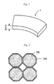
- the permanent magnet 1 is a Nd-Fe-B-based magnet. Further, Dy (dysprosium) for increasing the coercive force of the permanent magnet 1 is added. Incidentally, the contents of respective components are regarded as Nd: 27 to 30 wt%, Dy (or Tb): 0.01 to 8 wt%, B: 1 to 2 wt%, and Fe (electrolytic iron): 60 to 70 wt%. Furthermore, the permanent magnet 1 is constituted from a fan-shaped and thin film-like magnet as shown in Fig. 1. Fig. 1 is an overall view showing the permanent magnet 1 according to this embodiment.
- the permanent magnet 1 as used herein is a thin film-like permanent magnet having a thickness of 0.1 to 2 mm (2 mm in Fig. 1 ), and is prepared by sintering a green sheet molded from a Nd magnet powder in a slurry state as described later.
- the coercive force of the permanent magnet 1 is improved by coating surfaces of Nd magnet particles 35 constituting the permanent magnet 1 with Dy layers 36 as shown in Fig. 2.
- Fig. 2 is an enlarged view showing the Nd magnet particles constituting the permanent magnet 1.
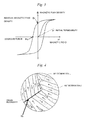
- Fig. 3 is a graph showing a hysteresis curve of a ferromagnetic body
- Fig. 4 is a schematic view showing a magnetic domain structure of the ferromagnetic body.
- the coercive force of the permanent magnet is the intensity of a magnetic field necessary for making magnetic polarization zero (that is to say, for magnetization reversal) when the magnetic field is applied from a magnetized state in the opposite direction. Accordingly, if the magnetization reversal can be inhibited, high coercive force can be obtained.
- magnetization processes of a magnetic body include rotational magnetization based on rotation of magnetic moment and domain wall displacement in which domain walls (consisting of a 90° domain wall and a 180° domain wall) as boundaries of magnetic domains move.
- the magnet powder when the magnet powder is finely pulverized by wet pulverization as described later, slight amounts (for example, 0.01 to 8 wt% based on the magnet powder (the amount of Dy added based on Nd, being taken as weight conversion of Dy distribution particularly when a Dy compound is added) of the Dy compound and a dispersing agent are added.
- This causes the Dy compound to be uniformly adhered to the particle surfaces of the Nd magnet particles 35 by wet dispersion to form the Dy layers 36 shown in Fig. 2 , when the Dy compound-added magnet powder is sintered thereafter.
- Dy is unevenly distributed in a boundary face of the magnet particle as shown in Fig.
- the Dy layer 36 is not required to be a layer composed of only the Dy compound, and may be a layer composed of a mixture of Dy and Nd.
- Tb terbium
- Dy compound a Tb (terbium) compound
- layers of the Tb compound are similarly formed on the surfaces of the Nd magnet particles 35, and the residual magnetization of the permanent magnet 1 can be further improved by forming the Tb layers.
- FIG. 5 is an explanatory view showing production steps of the permanent magnet 1 of this embodiment.
- an ingot including 27 to 30 wt% of Nd, 60 to 70 wt% of Fe and 1 to 2 wt% of B is produced. Thereafter, the ingot is crudely pulverized to a size of about 200 ⁇ m with a stamp mill, a crusher or the like. Then, the crudely pulverized magnet powder is finely pulverized to a size of about 0.3 to 5 ⁇ m by a wet method using a bead mill, and the magnet powder is dispersed in a solution to prepare a slip.
- the wet pulverization 4 kg of toluene based on 5 kg of the magnet powder is used as a solvent, and 0.05 kg of a phosphate-based dispersing agent is further added as a dispersing agent. Further, during the wet pulverization, 0.01 to 8 wt% of the Dy compound is added to the magnet powder, thereby dispersing the Dy compound in the solvent together with the magnet powder.
- detailed dispersing conditions are as follows:
- a substance soluble in the solvent of the slurry is preferably used as the Dy compound added.
- a Dy-containing organic material more particularly a dysprosium cation-containing organic acid salt (an aliphatic carboxylate, an aromatic carboxylate, an alicyclic carboxylate, an alkyl aromatic carboxylate or the like), a dysprosium cation-containing organic complex (an acetylacetonate, a phthalocyan complex, a merocyan complex or the like) and an organic metal compound other than the above may be mentioned.
- Dy or the Dy compound it also becomes possible to uniformly adhere Dy or the Dy compound to the surface of the Nd magnet particle by adding Dy or the Dy compound pulverized into fine particles, at the time of wet dispersion, and uniformly dispersing the fine particles, even when it is insoluble in the solvent.
- the solvent used for pulverization there is no particular limitation on the solvent used for pulverization, and there can be used an alcohol such as isopropyl alcohol, ethanol or methanol, a lower hydrocarbon such as pentane or hexane, an aromatic compound such as benzene, toluene or xylene, a ketone, a mixture thereof or the like.
- an alcohol such as isopropyl alcohol, ethanol or methanol
- a lower hydrocarbon such as pentane or hexane
- an aromatic compound such as benzene, toluene or xylene, a ketone, a mixture thereof or the like.
- isopropyl alcohol or the like is preferred.
- a resin binder is added to and mixed with the slip prepared. Subsequently, the magnet powder and the resin binder are kneaded to produce a slurry 41.
- a material used as the resin binder is not particularly limited, and may be each of various thermoplastic resin single substances or mixtures thereof, or various thermosetting resin single substances or mixtures thereof. Physical properties, natures and the like of the respective ones may be any, as long as they are within the range in which desired characteristics are obtained. For example, a methacrylic resin may be mentioned.
- a green sheet 42 is formed from the slurry 41 produced.
- a method for forming the green sheet 42 can be performed, for example, by a method of coating a supporting substrate such as a separator as needed with the produced slurry 41 by an appropriate system, followed by drying, or the like.
- the coating system is preferably a system excellent in layer thickness controllability, such as a doctor blade method.
- a defoaming treatment is sufficiently performed so that no air bubbles remain in a developed layer, by combined use of a defoaming agent or the like.
- detailed coating conditions are as follows:
- a pulsed field is applied to the green sheet 42 coated on the supporting substrate, in a direction crossing to a transfer direction, thereby orientating the magnetic field in a desired direction.
- the green sheet 42 formed from the slurry 41 is divided into a desired product shape (for example, in this embodiment, the fan shape shown in Fig. 1 ). Thereafter, sintering is performed at 1,100°C for about 1 hour. Incidentally, the sintering is performed under an Ar or vacuum atmosphere, and as a result of the sintering, the permanent magnet 1 composed of a sheet-like magnet is produced.
- a magnet raw material including 27 to 30 wt% of Nd, 60 to 70 wt% of Fe and 1 to 2 wt% of B is wet-pulverized in a solvent, then a resin binder is added to the pulverized magnet powder, the magnet powder and the resin binder are kneaded to produce a slurry 41, and the slurry produced is molded into a sheet form to obtain a green sheet 42, which is sintered to produce the permanent magnet 1.
- the contraction due to sintering becomes uniform, whereby the deformations such as warpage and depressions do not occur after sintering, and further, it is unnecessary to perform the conventional correcting processing after sintering, which can simplify the production steps, because the pressure unevenness at the time of pressing disappears. Therefore, it becomes possible to mold the permanent magnet 1 with a high degree of dimension accuracy. Furthermore, even when preparing a thin film of the permanent magnet 1, the magnetic characteristics are not deteriorated by the processing-deteriorated layer on the surface. In addition, the production steps can be simplified for the Nd-based magnet capable of especially securing a high coercive force of rear earth magnets, and the Nd-based magnet can be molded with high dimensional accuracy.
- the invention should not be construed as being limited to the above-mentioned example, and various improvements and modifications are of course possible within the range not departing from the gist of the invention.
- the method for dispersing the magnet powder and the Dy compound in the solvent the crudely pulverized magnet powder is wet-pulverized in the solvent together with the Dy compound, thereby dispersing them in the solvent, as shown in Fig. 5 .
- an ingot of Nd-Fe-B is first pulverized and thereafter a Dy compound is added thereto and dispersed in a solvent to produce a green sheet.
- a Dy compound is added thereto and dispersed in a solvent to produce a green sheet.
- an ingot of Nd-Fe-Dy-B that previously contains Dy may be pulverized and dispersed in a solvent to produce a green sheet.
- the amount of Dy to be contained in the ingot must be from 20 to 30 wt% based on Nd.
- a permanent magnet motor such as a vibration motor mounted on a cellular phone, a driving motor mounted on a hybrid car or a spindle motor for rotating a disk of a hard disk drive.
- the pulverizing conditions, kneading conditions and sintering conditions of the magnet powder should not be construed as being limited to the conditions described in the above-mentioned example.
- a Dy compound and a dispersing agent are added to the magnet powder in wet-pulverizing the magnet raw material and the Dy compound and the magnet raw material are dispersed in the solvent whereby the Dy compound is unevenly distributed and localized in the grain boundary of the magnet particle so as to enhance the coercive force of the magnet.
- the constitution of adding the Dy compound is not limited thereto but may be any other constitution to realize the same effect of enhancing the coercive force.
- the surface of the prepared green sheet 42 may be uniformly coated with a Dy compound.
- the sintered magnet may be uniformly coated with a Dy compound and then this may be heat-treated.
- Dy covers the surface of the sheet magnet and is unevenly distributed thereon, thereby being able to enhance the coercive force of the magnet, and the total amount of Dy may be reduced.
- a permanent magnet is constituted by a magnet produced by sintering a green sheet which is produced by mixing a magnet raw material with a resin binder and molding the resulting mixture. Accordingly, the contraction due to sintering becomes uniform, whereby the deformations such as warpage and depressions do not occur after sintering, and further, it is unnecessary to perform the conventional correcting processing after sintering, which can simplify the production steps, because the pressure unevenness at the time of pressing disappears. Therefore, it becomes possible to mold the permanent magnet with a high degree of dimension accuracy. Furthermore, even when the permanent magnet is reduced in film thickness, the magnetic characteristics are not deteriorated by the processing-deteriorated layer on the surface.
Landscapes
- Engineering & Computer Science (AREA)
- Power Engineering (AREA)
- Manufacturing & Machinery (AREA)
- Chemical & Material Sciences (AREA)
- Crystallography & Structural Chemistry (AREA)
- Inorganic Chemistry (AREA)
- Hard Magnetic Materials (AREA)
- Powder Metallurgy (AREA)
- Permanent Field Magnets Of Synchronous Machinery (AREA)
Abstract
Description
- The present invention relates to a permanent magnet and a method for producing a permanent magnet.
- In recent years, a reduction in size and weight, an increase in power and an increase in efficiency have been required for permanent magnet motors used in hybrid vehicles, hard disk drives or the like. In particular, with recent requirement for a reduction in size of hard disk drives, a further reduction in size and thickness has been required for voice coil motors (hereinafter referred to as VCMs) used for head driving of hard disk drives as shown in Patent Document 1 (
JP-A 2006-286819
In realizing the reduction in size and thickness of the above-mentioned VCMs, a reduction in film thickness and further improvement in magnetic characteristics have been required for permanent magnets to be buried in the VCMs. As the permanent magnets, there are ferrite magnets, Sm-Co-based magnets, Nd-Fe-B-based magnets, Sm2Fe17Nx-based magnets, etc.; and in particular, Nd-Fe-B-based magnets having high coercive force are used as the permanent magnets for permanent magnet motors. - Here, as a method for producing permanent magnets for use in permanent magnet motors, a powder sintering method is generally used. In the powder sintering method for use herein, a raw material is first pulverized with a jet mill (dry pulverization) to produce a magnet powder as shown in
Fig. 6 . Thereafter the magnet powder is placed in a mold, and press-molded to a desired shape while applying thereto a magnetic field from the outside. Then, the solid magnet powder thus-molded to the desired shape is sintered at a predetermined temperature (for example, 1100°C in the case of the Nd-Fe-B-based magnet), thereby producing the permanent magnet. - Patent Document 1:
JP-A 2006-286819 Page 2, Page 3,Fig. 4 ) - However, when the permanent magnet is produced by the above-mentioned powder sintering method, there have been the following problems. That is to say, in the powder sintering method, it is necessary to secure a predetermined porosity in a press-molded magnet powder in order to perform magnetic field orientation. And when the magnet powder having the predetermined porosity is sintered, it is difficult to uniformly perform contraction which occurs at the time of sintering, and deformations such as warpage and depressions occur after sintering. Further, since pressure unevenness occurs at the time of pressing the magnet powder, sparse and dense of the magnet after sintering are formed to generate strain on a surface of the magnet. Conventionally, it has therefore been required to compression-mold the magnet powder to a larger size than that of a desired shape, previously assuming that strain is generated on the surface of the magnet. Then, cutting and polishing operations using a diamond have been performed after sintering to perform processing for correcting to the desired shape. As a result, production steps increase, and there is a possibility of deteriorating qualities of the permanent magnet produced.
- Further, particularly in the permanent magnet used in the VCMs as described above, a reduction in film thickness (for example, 1 mm or less in thickness) has been required. And the magnet reduced in film thickness has a large ratio of a processing-deteriorated layer on a surface, which occurs in the case of processing the surface, compared to a thick magnet. Accordingly, when the thin film-like permanent magnet is produced by the above-mentioned powder sintering method, a problem of further deteriorating magnetic characteristics has also been encountered.
- The invention has been made in order to solve the above-mentioned conventional problems, and an object of the invention is to provide a permanent magnet, in which the deformations such as warpage and depressions do not occur after sintering, because the contraction due to sintering becomes uniform, further which requires no correcting processing after sintering to be able to simplify the production steps, because the pressure unevenness at the time of pressing disappears, and which is free from degradation of magnetic characteristics even when the permanent magnet is reduced in film thickness, and to provide a method for producing such a permanent magnet.
- Namely, the present invention relates to the following items (1) to (6).
- (1) A permanent magnet obtained by sintering a green sheet which is produced by mixing a magnet raw material with a resin binder and molding the resulting mixture.
- (2) The permanent magnet according to (1), in which the magnet raw material is an Nd-based magnet.
- (3) A method for producing a permanent magnet, the method including:
- a step of wet-pulverizing a magnet raw material,
- a step of adding a resin binder to the magnet raw material,
- a step of kneading the magnet raw material and the resin binder to produce a slurry,
- a step of molding the slurry into a sheet form to prepare a green sheet, and
- a step of sintering the green sheet.
- (4) A method for producing a permanent magnet, the method including:
- a step of dry-pulverizing a magnet raw material,
- a step of adding a resin binder to the magnet raw material,
- a step of kneading the magnet raw material and the resin binder to produce a slurry,
- a step of molding the slurry into a sheet form to prepare a green sheet, and
- a step of sintering the green sheet.
- (5) The method for producing a permanent magnet according to (3), in which the magnet raw material is an Nd-based magnet.
- (6) The method for producing a permanent magnet according to (4), in which the magnet raw material is an Nd-based magnet.
- According to the permanent magnet having the constitution of the above (1), the permanent magnet is constituted by the magnet produced by sintering a green sheet which is produced by mixing a magnet raw material with a resin binder and molding the resulting mixture. Accordingly, the contraction due to sintering becomes uniform, whereby the deformations such as warpage and depressions do not occur after sintering, and further, it is unnecessary to perform the conventional correcting processing after sintering, which can simplify the production steps, because the pressure unevenness at the time of pressing disappears. Therefore, it becomes possible to mold the permanent magnet with a high degree of dimension accuracy. Furthermore, even when the permanent magnet is reduced in film thickness, the magnetic characteristics are not deteriorated by the processing-deteriorated layer on the surface.
- According to the permanent magnet having the constitution of the above (2), it is possible to simplify the production method for an Nd-based magnet capable of especially securing a high coercive force and is possible to mold with a high degree of dimension accuracy.
- According to the method for producing a permanent magnet of the above (3), a permanent magnet is produced by adding a resin binder to a wet-pulverized magnet raw material; kneading the magnet raw material and the resin binder to produce a slurry; and sintering a green sheet molded from the slurry produced. Accordingly, the contraction due to sintering becomes uniform, whereby the deformations such as warpage and depressions do not occur after sintering, and further, it is unnecessary to perform the conventional correcting processing after sintering, which can simplify the production steps, because the pressure unevenness at the time of pressing disappears. Therefore, it becomes possible to mold the permanent magnet with a high degree of dimension accuracy. Furthermore, even when preparing a thin-film permanent magnet, the magnetic characteristics are not deteriorated by the processing-deteriorated layer on the surface.
- According to the method for producing a permanent magnet of the above (4), a permanent magnet is produced by adding a resin binder to a dry-pulverized magnet raw material; kneading the magnet raw material and the resin binder to produce a slurry; and sintering a green sheet molded from the slurry produced. Accordingly, the contraction due to sintering becomes uniform, whereby the deformations such as warpage and depressions do not occur after sintering, and further, it is unnecessary to perform the conventional correcting processing after sintering, which can simplify the production steps, because the pressure unevenness at the time of pressing disappears. Therefore, it becomes possible to mold the permanent magnet with a high degree of dimension accuracy. Furthermore, even when preparing a thin-film permanent magnet, the magnetic characteristics are not deteriorated by the processing-deteriorated layer on the surface.
- According to the method for producing a permanent magnet of the above (5) and (6), it is possible to simplify the production steps for an Nd-based magnet capable of especially securing a high coercive force and is possible to mold with a high degree of dimension accuracy.
-
-
Fig. 1 is an overall view showing a permanent magnet according to the present embodiment. -
Fig. 2 is an enlarged view showing Nd magnet particles constituting a permanent magnet. -
Fig. 3 is a graph showing a hysteresis curve of a ferromagnetic body. -
Fig. 4 is a schematic view showing a magnetic domain structure of a ferromagnetic body. -
Fig. 5 is an explanatory view showing production steps of the permanent magnet according to the present embodiment. -
Fig. 6 is an explanatory view showing production steps of a conventional permanent magnet. -
- 1
- Permanent Magnet
- 41
- Slurry
- 42
- Green Sheet
- A specific embodiment of a permanent magnet and a method for producing a permanent magnet according to the invention will be described in detail hereinunder with reference to the drawings.
- First, a constitution of a
permanent magnet 1 will be described usingFigs. 1 to 4 . In this embodiment, particularly, an explanation is given taking the permanent magnet to be buried in a VCM as an example.
Thepermanent magnet 1 according to this embodiment is a Nd-Fe-B-based magnet. Further, Dy (dysprosium) for increasing the coercive force of thepermanent magnet 1 is added. Incidentally, the contents of respective components are regarded as Nd: 27 to 30 wt%, Dy (or Tb): 0.01 to 8 wt%, B: 1 to 2 wt%, and Fe (electrolytic iron): 60 to 70 wt%. Furthermore, thepermanent magnet 1 is constituted from a fan-shaped and thin film-like magnet as shown inFig. 1. Fig. 1 is an overall view showing thepermanent magnet 1 according to this embodiment. - The
permanent magnet 1 as used herein is a thin film-like permanent magnet having a thickness of 0.1 to 2 mm (2 mm inFig. 1 ), and is prepared by sintering a green sheet molded from a Nd magnet powder in a slurry state as described later. - Further, in the
permanent magnet 1 according to this embodiment, the coercive force of thepermanent magnet 1 is improved by coating surfaces ofNd magnet particles 35 constituting thepermanent magnet 1 with Dy layers 36 as shown inFig. 2. Fig. 2 is an enlarged view showing the Nd magnet particles constituting thepermanent magnet 1. - A mechanism of improving the coercive force of the
permanent magnet 1 with the Dy layers 36 will be described below usingFig. 3 and Fig. 4. Fig. 3 is a graph showing a hysteresis curve of a ferromagnetic body, andFig. 4 is a schematic view showing a magnetic domain structure of the ferromagnetic body.
As shown inFig. 3 , the coercive force of the permanent magnet is the intensity of a magnetic field necessary for making magnetic polarization zero (that is to say, for magnetization reversal) when the magnetic field is applied from a magnetized state in the opposite direction. Accordingly, if the magnetization reversal can be inhibited, high coercive force can be obtained. Incidentally, magnetization processes of a magnetic body include rotational magnetization based on rotation of magnetic moment and domain wall displacement in which domain walls (consisting of a 90° domain wall and a 180° domain wall) as boundaries of magnetic domains move. - Here, in this embodiment, when the magnet powder is finely pulverized by wet pulverization as described later, slight amounts (for example, 0.01 to 8 wt% based on the magnet powder (the amount of Dy added based on Nd, being taken as weight conversion of Dy distribution particularly when a Dy compound is added) of the Dy compound and a dispersing agent are added. This causes the Dy compound to be uniformly adhered to the particle surfaces of the
Nd magnet particles 35 by wet dispersion to form the Dy layers 36 shown inFig. 2 , when the Dy compound-added magnet powder is sintered thereafter. As a result, Dy is unevenly distributed in a boundary face of the magnet particle as shown inFig. 4 , thereby being able to improve the coercive force of thepermanent magnet 1.
Further, in this embodiment, when the green sheet obtained by wet-mixing the Dy compound with the magnet raw material in a solvent is sintered under proper sintering conditions, Dy can be prevented from being diffused and penetrated (solid-solutionized) into themagnet particles 35. Here, it is known that the diffusion and penetration of Dy into themagnet particles 35 decreases the residual magnetization (magnetization at the time when the intensity of the magnetic field is made zero) of the magnet. Accordingly, in this embodiment, the residual magnetization of thepermanent magnet 1 can be prevented from being decreased.
Incidentally, theDy layer 36 is not required to be a layer composed of only the Dy compound, and may be a layer composed of a mixture of Dy and Nd. Further, a Tb (terbium) compound may be added in place of the Dy compound, whereby it becomes possible to similarly improve the residual magnetization of thepermanent magnet 1. When Tb is added, layers of the Tb compound are similarly formed on the surfaces of theNd magnet particles 35, and the residual magnetization of thepermanent magnet 1 can be further improved by forming the Tb layers. - A method for producing the
permanent magnet 1 according to this embodiment will be described below usingFig. 5. Fig. 5 is an explanatory view showing production steps of thepermanent magnet 1 of this embodiment. - First, an ingot including 27 to 30 wt% of Nd, 60 to 70 wt% of Fe and 1 to 2 wt% of B is produced. Thereafter, the ingot is crudely pulverized to a size of about 200 µm with a stamp mill, a crusher or the like. Then, the crudely pulverized magnet powder is finely pulverized to a size of about 0.3 to 5 µm by a wet method using a bead mill, and the magnet powder is dispersed in a solution to prepare a slip. Incidentally, in the wet pulverization, 4 kg of toluene based on 5 kg of the magnet powder is used as a solvent, and 0.05 kg of a phosphate-based dispersing agent is further added as a dispersing agent. Further, during the wet pulverization, 0.01 to 8 wt% of the Dy compound is added to the magnet powder, thereby dispersing the Dy compound in the solvent together with the magnet powder. Incidentally, detailed dispersing conditions are as follows:
- Dispersing device:
- bead mill
- Dispersing medium:
- zirconia beads
- Here, a substance soluble in the solvent of the slurry is preferably used as the Dy compound added. For example, a Dy-containing organic material, more particularly a dysprosium cation-containing organic acid salt (an aliphatic carboxylate, an aromatic carboxylate, an alicyclic carboxylate, an alkyl aromatic carboxylate or the like), a dysprosium cation-containing organic complex (an acetylacetonate, a phthalocyan complex, a merocyan complex or the like) and an organic metal compound other than the above may be mentioned.
Further, it also becomes possible to uniformly adhere Dy or the Dy compound to the surface of the Nd magnet particle by adding Dy or the Dy compound pulverized into fine particles, at the time of wet dispersion, and uniformly dispersing the fine particles, even when it is insoluble in the solvent. - Furthermore, there is no particular limitation on the solvent used for pulverization, and there can be used an alcohol such as isopropyl alcohol, ethanol or methanol, a lower hydrocarbon such as pentane or hexane, an aromatic compound such as benzene, toluene or xylene, a ketone, a mixture thereof or the like. In particular, isopropyl alcohol or the like is preferred.
- After dispersion of the magnet powder, a resin binder is added to and mixed with the slip prepared. Subsequently, the magnet powder and the resin binder are kneaded to produce a
slurry 41. Incidentally, a material used as the resin binder is not particularly limited, and may be each of various thermoplastic resin single substances or mixtures thereof, or various thermosetting resin single substances or mixtures thereof. Physical properties, natures and the like of the respective ones may be any, as long as they are within the range in which desired characteristics are obtained. For example, a methacrylic resin may be mentioned. - Subsequently, a
green sheet 42 is formed from theslurry 41 produced. A method for forming thegreen sheet 42 can be performed, for example, by a method of coating a supporting substrate such as a separator as needed with the producedslurry 41 by an appropriate system, followed by drying, or the like. Incidentally, the coating system is preferably a system excellent in layer thickness controllability, such as a doctor blade method. Further, it is preferred that a defoaming treatment is sufficiently performed so that no air bubbles remain in a developed layer, by combined use of a defoaming agent or the like. Incidentally, detailed coating conditions are as follows: - Coating system:
- doctor blade
- Gap:
- 1 mm
- Supporting substrate:
- silicone-treated polyester film
- Drying conditions:
- 130°C×30 min after 90°C×10 min
- Further, a pulsed field is applied to the
green sheet 42 coated on the supporting substrate, in a direction crossing to a transfer direction, thereby orientating the magnetic field in a desired direction. Incidentally, it is necessary to determine the direction in which the magnetic field is orientated, taking into consideration the magnetic field direction required for thepermanent magnet 1 molded from thegreen sheet 42. - Then, the
green sheet 42 formed from theslurry 41 is divided into a desired product shape (for example, in this embodiment, the fan shape shown inFig. 1 ). Thereafter, sintering is performed at 1,100°C for about 1 hour. Incidentally, the sintering is performed under an Ar or vacuum atmosphere, and as a result of the sintering, thepermanent magnet 1 composed of a sheet-like magnet is produced. - As described in the above, for the
permanent magnet 1 and according to the production method for thepermanent magnet 1 of this embodiment, a magnet raw material including 27 to 30 wt% of Nd, 60 to 70 wt% of Fe and 1 to 2 wt% of B is wet-pulverized in a solvent, then a resin binder is added to the pulverized magnet powder, the magnet powder and the resin binder are kneaded to produce aslurry 41, and the slurry produced is molded into a sheet form to obtain agreen sheet 42, which is sintered to produce thepermanent magnet 1. Accordingly, the contraction due to sintering becomes uniform, whereby the deformations such as warpage and depressions do not occur after sintering, and further, it is unnecessary to perform the conventional correcting processing after sintering, which can simplify the production steps, because the pressure unevenness at the time of pressing disappears. Therefore, it becomes possible to mold thepermanent magnet 1 with a high degree of dimension accuracy. Furthermore, even when preparing a thin film of thepermanent magnet 1, the magnetic characteristics are not deteriorated by the processing-deteriorated layer on the surface.
In addition, the production steps can be simplified for the Nd-based magnet capable of especially securing a high coercive force of rear earth magnets, and the Nd-based magnet can be molded with high dimensional accuracy. - Incidentally, the invention should not be construed as being limited to the above-mentioned example, and various improvements and modifications are of course possible within the range not departing from the gist of the invention. For example, in this embodiment, as the method for dispersing the magnet powder and the Dy compound in the solvent, the crudely pulverized magnet powder is wet-pulverized in the solvent together with the Dy compound, thereby dispersing them in the solvent, as shown in
Fig. 5 . However, it is also possible to disperse them by the following method. - (1) First, the crudely pulverized magnet powder is finely pulverized to a size of about 0.3 to 5 11m by dry pulverization using a ball mill, a jet mill or the like.
- (2) Then, the finely pulverized magnet powder is added to the solvent, and allowed to be uniformly dispersed in the solvent. In that case, the dispersing agent and the Dy compound are also added to the solvent.
- (3) The magnet powder and the resin powder dispersed in the solvent are kneaded to produce the
slurry 41. - In this embodiment, an ingot of Nd-Fe-B is first pulverized and thereafter a Dy compound is added thereto and dispersed in a solvent to produce a green sheet. Apart from this, however, an ingot of Nd-Fe-Dy-B that previously contains Dy may be pulverized and dispersed in a solvent to produce a green sheet. In such a case, the amount of Dy to be contained in the ingot must be from 20 to 30 wt% based on Nd.
- Further, in this embodiment, description is made taking the permanent magnet to be buried in the VCM as an example. However, it is also of course possible to be applied to the permanent magnet buried in a permanent magnet motor such as a vibration motor mounted on a cellular phone, a driving motor mounted on a hybrid car or a spindle motor for rotating a disk of a hard disk drive.
- Furthermore, the pulverizing conditions, kneading conditions and sintering conditions of the magnet powder should not be construed as being limited to the conditions described in the above-mentioned example.
- In this embodiment, a Dy compound and a dispersing agent are added to the magnet powder in wet-pulverizing the magnet raw material and the Dy compound and the magnet raw material are dispersed in the solvent whereby the Dy compound is unevenly distributed and localized in the grain boundary of the magnet particle so as to enhance the coercive force of the magnet. However, the constitution of adding the Dy compound is not limited thereto but may be any other constitution to realize the same effect of enhancing the coercive force.
For example, the surface of the preparedgreen sheet 42 may be uniformly coated with a Dy compound. The sintered magnet may be uniformly coated with a Dy compound and then this may be heat-treated. As a result, Dy covers the surface of the sheet magnet and is unevenly distributed thereon, thereby being able to enhance the coercive force of the magnet, and the total amount of Dy may be reduced. - While the invention has been described in detail and with reference to specific embodiments thereof, it will be apparent to one skilled in the art that various changes and modifications can be made therein without departing from the spirit and scope thereof.
This application is based on a Japanese patent application No.2008-069382 filed March 18, 2008
All the references cited are incorporated herein as a whole. - According to the present invention, a permanent magnet is constituted by a magnet produced by sintering a green sheet which is produced by mixing a magnet raw material with a resin binder and molding the resulting mixture. Accordingly, the contraction due to sintering becomes uniform, whereby the deformations such as warpage and depressions do not occur after sintering, and further, it is unnecessary to perform the conventional correcting processing after sintering, which can simplify the production steps, because the pressure unevenness at the time of pressing disappears. Therefore, it becomes possible to mold the permanent magnet with a high degree of dimension accuracy. Furthermore, even when the permanent magnet is reduced in film thickness, the magnetic characteristics are not deteriorated by the processing-deteriorated layer on the surface.
Claims (6)
- A permanent magnet obtained by sintering a green sheet which is produced by mixing a magnet raw material with a resin binder and molding the resulting mixture.
- The permanent magnet according to claim 1, wherein the magnet raw material is an Nd-based magnet.
- A method for producing a permanent magnet, said method comprising:a step of wet-pulverizing a magnet raw material,a step of adding a resin binder to the magnet raw material,a step of kneading the magnet raw material and the resin binder to produce a slurry,a step of molding the slurry into a sheet form to prepare a green sheet, anda step of sintering the green sheet.
- A method for producing a permanent magnet, said method comprising:a step of dry-pulverizing a magnet raw material,a step of adding a resin binder to the magnet raw material,a step of kneading the magnet raw material and the resin binder to produce a slurry,a step of molding the slurry into a sheet form to prepare a green sheet, anda step of sintering the green sheet.
- The method for producing a permanent magnet according to claim 3, wherein the magnet raw material is an Nd-based magnet.
- The method for producing a permanent magnet according to claim 4, wherein the magnet raw material is an Nd-based magnet.
Applications Claiming Priority (2)
| Application Number | Priority Date | Filing Date | Title |
|---|---|---|---|
| JP2008069382A JP4872109B2 (en) | 2008-03-18 | 2008-03-18 | Permanent magnet and method for manufacturing permanent magnet |
| PCT/JP2009/055191 WO2009116539A1 (en) | 2008-03-18 | 2009-03-17 | Permanent magnet and method for manufacturing the same |
Publications (2)
| Publication Number | Publication Date |
|---|---|
| EP2256758A1 true EP2256758A1 (en) | 2010-12-01 |
| EP2256758A4 EP2256758A4 (en) | 2011-07-06 |
Family
ID=41090940
Family Applications (1)
| Application Number | Title | Priority Date | Filing Date |
|---|---|---|---|
| EP09722877A Withdrawn EP2256758A4 (en) | 2008-03-18 | 2009-03-17 | PERMANENT MAGNET AND METHOD FOR MANUFACTURING THE SAME |
Country Status (6)
| Country | Link |
|---|---|
| US (1) | US20110012700A1 (en) |
| EP (1) | EP2256758A4 (en) |
| JP (1) | JP4872109B2 (en) |
| KR (1) | KR20100127233A (en) |
| CN (1) | CN101978445B (en) |
| WO (1) | WO2009116539A1 (en) |
Cited By (3)
| Publication number | Priority date | Publication date | Assignee | Title |
|---|---|---|---|---|
| EP2827350A4 (en) * | 2012-03-12 | 2016-01-20 | Nitto Denko Corp | Rare-earth permanent magnet and method for manufacturing rare-earth permanent magnet |
| EP2827347A4 (en) * | 2012-03-12 | 2016-01-20 | Nitto Denko Corp | Rare earth permanent magnet and rare earth permanent magnet production method |
| EP2827348A4 (en) * | 2012-03-12 | 2016-01-20 | Nitto Denko Corp | RARE EARTH PERMANENT MAGNET AND METHOD FOR MANUFACTURING RARE EARTH PERMANENT MAGNET |
Families Citing this family (18)
| Publication number | Priority date | Publication date | Assignee | Title |
|---|---|---|---|---|
| JP2009225608A (en) | 2008-03-18 | 2009-10-01 | Nitto Denko Corp | Permanent magnet for motor and method of manufacturing the permanent magnet for motor |
| JP5417632B2 (en) * | 2008-03-18 | 2014-02-19 | 日東電工株式会社 | Permanent magnet and method for manufacturing permanent magnet |
| CN102549685B (en) * | 2010-03-31 | 2014-04-02 | 日东电工株式会社 | Permanent magnet and manufacturing method of permanent magnet |
| JP2011216596A (en) * | 2010-03-31 | 2011-10-27 | Nitto Denko Corp | Permanent magnet and method for manufacturing the same |
| US20130141196A1 (en) * | 2011-06-24 | 2013-06-06 | Nitto Denko Corporation | Rare-earth permanent magnet and method for manufacturing rare-earth permanent magnet |
| US20130141194A1 (en) * | 2011-06-24 | 2013-06-06 | Nitto Denko Corporation | Rare-earth permanent magnet and method for manufacturing rare-earth permanent magnet |
| EP2685472A4 (en) * | 2011-06-24 | 2015-04-08 | Nitto Denko Corp | Rare earth permanent magnet and production method for rare earth permanent magnet |
| WO2012176514A1 (en) * | 2011-06-24 | 2012-12-27 | 日東電工株式会社 | Rare earth permanent magnet and method for producing rare earth permanent magnet |
| JP5103553B1 (en) * | 2011-06-24 | 2012-12-19 | 日東電工株式会社 | Rare earth permanent magnet and method for producing rare earth permanent magnet |
| JP5908247B2 (en) * | 2011-09-30 | 2016-04-26 | 日東電工株式会社 | Method for manufacturing permanent magnet |
| JP5298180B2 (en) * | 2011-11-24 | 2013-09-25 | 日東電工株式会社 | Permanent magnet for motor and method for manufacturing permanent magnet for motor |
| JP2013191608A (en) * | 2012-03-12 | 2013-09-26 | Nitto Denko Corp | Rare earth permanent magnet and method for producing rare earth permanent magnet |
| JP2013191610A (en) * | 2012-03-12 | 2013-09-26 | Nitto Denko Corp | Rare earth permanent magnet and method for producing rare earth permanent magnet |
| JP2013191607A (en) * | 2012-03-12 | 2013-09-26 | Nitto Denko Corp | Rare earth permanent magnet and method for producing rare earth permanent magnet |
| JP2013191609A (en) * | 2012-03-12 | 2013-09-26 | Nitto Denko Corp | Rare earth permanent magnet and method for producing rare earth permanent magnet |
| JP6196587B2 (en) * | 2014-07-08 | 2017-09-13 | 紀伊産業株式会社 | Wide-mouth container with auxiliary equipment |
| KR102758091B1 (en) * | 2020-04-23 | 2025-01-22 | 현대자동차주식회사 | Method for manufacturing rare-earth permanent magnet and Rare-earth permanent magnet manufactured thereby |
| CN115440495B (en) * | 2022-10-10 | 2026-02-27 | 烟台东星磁性材料股份有限公司 | A method for improving the coercivity of neodymium iron boron magnets and magnets prepared by the method |
Family Cites Families (20)
| Publication number | Priority date | Publication date | Assignee | Title |
|---|---|---|---|---|
| US4762574A (en) * | 1985-06-14 | 1988-08-09 | Union Oil Company Of California | Rare earth-iron-boron premanent magnets |
| JPH01150303A (en) * | 1987-12-08 | 1989-06-13 | Mitsubishi Steel Mfg Co Ltd | Magnetic anisotropy type sintered magnet and manufacture thereof |
| US5427734A (en) * | 1992-06-24 | 1995-06-27 | Sumitomo Special Metals Co., Ltd. | Process for preparing R-Fe-B type sintered magnets employing the injection molding method |
| JPH06112023A (en) * | 1992-09-28 | 1994-04-22 | Seiko Epson Corp | Rotor magnet and manufacturing method thereof |
| JPH07201619A (en) * | 1993-12-27 | 1995-08-04 | Sumitomo Special Metals Co Ltd | Production of r-fe-b based sintered anisotropic permanent magnet |
| JPH088111A (en) * | 1994-06-23 | 1996-01-12 | Murata Mfg Co Ltd | Anisotropic permanent magnet and its manufacturing method |
| JPH08222912A (en) * | 1995-02-17 | 1996-08-30 | Murata Mfg Co Ltd | Irreversible circuit element |
| EP0778594B1 (en) * | 1995-06-26 | 2004-09-29 | Neomax Co., Ltd. | Process for producing sintered rare earth magnet |
| JPH10270911A (en) * | 1997-03-26 | 1998-10-09 | Murata Mfg Co Ltd | Irreversible circuit element and its mounting structure |
| JP3538526B2 (en) * | 1997-07-03 | 2004-06-14 | 三菱電機株式会社 | Semiconductor integrated circuit device |
| JPH11195551A (en) * | 1997-12-27 | 1999-07-21 | Murata Mfg Co Ltd | Method of manufacturing magnet-integrated Faraday element |
| US6179894B1 (en) * | 1999-11-29 | 2001-01-30 | Delphi Technologies, Inc. | Method of improving compressibility of a powder and articles formed thereby |
| JPWO2002021543A1 (en) * | 2000-09-08 | 2004-01-15 | Necトーキン株式会社 | Permanent magnet, magnetic core using it as a magnet for magnetic bias, and inductance component using the same |
| US6753751B2 (en) * | 2000-11-30 | 2004-06-22 | Nec Tokin Corporation | Magnetic core including magnet for magnetic bias and inductor component using the same |
| JP2004281873A (en) * | 2003-03-18 | 2004-10-07 | Hitachi Metals Ltd | Method for manufacturing rare earth magnet |
| JP4525072B2 (en) * | 2003-12-22 | 2010-08-18 | 日産自動車株式会社 | Rare earth magnet and manufacturing method thereof |
| JP4234581B2 (en) * | 2003-12-25 | 2009-03-04 | 株式会社日立製作所 | Rare earth magnet, manufacturing method thereof and motor |
| JP2006286819A (en) | 2005-03-31 | 2006-10-19 | Tdk Corp | Rare earth sintered magnet and vcm device using the same |
| JP4415980B2 (en) * | 2006-08-30 | 2010-02-17 | 株式会社日立製作所 | High resistance magnet and motor using the same |
| JP5417632B2 (en) * | 2008-03-18 | 2014-02-19 | 日東電工株式会社 | Permanent magnet and method for manufacturing permanent magnet |
-
2008
- 2008-03-18 JP JP2008069382A patent/JP4872109B2/en not_active Expired - Fee Related
-
2009
- 2009-03-17 KR KR1020107020900A patent/KR20100127233A/en not_active Ceased
- 2009-03-17 US US12/933,006 patent/US20110012700A1/en not_active Abandoned
- 2009-03-17 CN CN200980109639.0A patent/CN101978445B/en not_active Expired - Fee Related
- 2009-03-17 EP EP09722877A patent/EP2256758A4/en not_active Withdrawn
- 2009-03-17 WO PCT/JP2009/055191 patent/WO2009116539A1/en not_active Ceased
Cited By (4)
| Publication number | Priority date | Publication date | Assignee | Title |
|---|---|---|---|---|
| EP2827350A4 (en) * | 2012-03-12 | 2016-01-20 | Nitto Denko Corp | Rare-earth permanent magnet and method for manufacturing rare-earth permanent magnet |
| EP2827347A4 (en) * | 2012-03-12 | 2016-01-20 | Nitto Denko Corp | Rare earth permanent magnet and rare earth permanent magnet production method |
| EP2827348A4 (en) * | 2012-03-12 | 2016-01-20 | Nitto Denko Corp | RARE EARTH PERMANENT MAGNET AND METHOD FOR MANUFACTURING RARE EARTH PERMANENT MAGNET |
| US10770207B2 (en) | 2012-03-12 | 2020-09-08 | Nitto Denko Corporation | Rare-earth permanent magnet and method for manufacturing rare-earth permanent magnet |
Also Published As
| Publication number | Publication date |
|---|---|
| JP4872109B2 (en) | 2012-02-08 |
| EP2256758A4 (en) | 2011-07-06 |
| CN101978445A (en) | 2011-02-16 |
| WO2009116539A1 (en) | 2009-09-24 |
| KR20100127233A (en) | 2010-12-03 |
| CN101978445B (en) | 2013-10-23 |
| US20110012700A1 (en) | 2011-01-20 |
| JP2009224670A (en) | 2009-10-01 |
Similar Documents
| Publication | Publication Date | Title |
|---|---|---|
| EP2256758A1 (en) | Permanent magnet and method for manufacturing the same | |
| US9275778B2 (en) | Permanent magnet and method for manufacturing the same | |
| US8333848B2 (en) | Permanent magnet and process for producing permanent magnet | |
| US9093218B2 (en) | Permanent magnet for motor, and method for manufacturing the permanent magnet for motor | |
| Cui et al. | Manufacturing processes for permanent magnets: Part I—sintering and casting | |
| KR101479373B1 (en) | Permanent magnet and process for producing permanent magnet | |
| CN111636035B (en) | Heavy rare earth alloy, neodymium iron boron permanent magnet material, raw materials and preparation method | |
| CN101794651A (en) | Rare earth magnet | |
| EP2503567B1 (en) | Manufacturing method for permanent magnet | |
| CN1477654A (en) | Magnet and motor using the same | |
| JP2012050329A (en) | Permanent magnet for motor and manufacturing method of permanent magnet for motor | |
| JP2012004576A (en) | Permanent magnet and method of producing the same | |
| CN102511070A (en) | Permanent magnet and manufacturing method of permanent magnet | |
| JP2015207687A (en) | Permanent magnet and method for manufacturing permanent magnet | |
| KR102953040B1 (en) | Method for manufacturing re-fe-b sintered magnet using dry coating and re-fe-b sintered magnet manufactured thereby |
Legal Events
| Date | Code | Title | Description |
|---|---|---|---|
| PUAI | Public reference made under article 153(3) epc to a published international application that has entered the european phase |
Free format text: ORIGINAL CODE: 0009012 |
|
| 17P | Request for examination filed |
Effective date: 20100914 |
|
| AK | Designated contracting states |
Kind code of ref document: A1 Designated state(s): AT BE BG CH CY CZ DE DK EE ES FI FR GB GR HR HU IE IS IT LI LT LU LV MC MK MT NL NO PL PT RO SE SI SK TR |
|
| AX | Request for extension of the european patent |
Extension state: AL BA RS |
|
| RIN1 | Information on inventor provided before grant (corrected) |
Inventor name: FUKUDA, YUUKI Inventor name: NAKAYAMA, JUNICHI Inventor name: KUME, KATSUYA Inventor name: OZEKI, IZUMI Inventor name: HOSHINO, TOSHINOBU Inventor name: HORIO, TOMOKAZU Inventor name: NAKAMURA, KENJI |
|
| DAX | Request for extension of the european patent (deleted) | ||
| A4 | Supplementary search report drawn up and despatched |
Effective date: 20110609 |
|
| RIC1 | Information provided on ipc code assigned before grant |
Ipc: H01F 41/02 20060101AFI20091013BHEP Ipc: H01F 1/057 20060101ALI20110601BHEP Ipc: H02K 15/03 20060101ALI20110601BHEP Ipc: H01F 1/08 20060101ALI20110601BHEP Ipc: H01F 1/053 20060101ALI20110601BHEP Ipc: H01F 1/055 20060101ALI20110601BHEP |
|
| RAP1 | Party data changed (applicant data changed or rights of an application transferred) |
Owner name: TOYOTA JIDOSHA KABUSHIKI KAISHA Owner name: NITTO DENKO CORPORATION |
|
| STAA | Information on the status of an ep patent application or granted ep patent |
Free format text: STATUS: EXAMINATION IS IN PROGRESS |
|
| 17Q | First examination report despatched |
Effective date: 20170504 |
|
| STAA | Information on the status of an ep patent application or granted ep patent |
Free format text: STATUS: THE APPLICATION IS DEEMED TO BE WITHDRAWN |
|
| 18D | Application deemed to be withdrawn |
Effective date: 20170915 |