EP2256529A1 - Optical connector - Google Patents
Optical connector Download PDFInfo
- Publication number
- EP2256529A1 EP2256529A1 EP09721838A EP09721838A EP2256529A1 EP 2256529 A1 EP2256529 A1 EP 2256529A1 EP 09721838 A EP09721838 A EP 09721838A EP 09721838 A EP09721838 A EP 09721838A EP 2256529 A1 EP2256529 A1 EP 2256529A1
- Authority
- EP
- European Patent Office
- Prior art keywords
- intermediate member
- optical connector
- ferrule
- plastic
- plug
- Prior art date
- Legal status (The legal status is an assumption and is not a legal conclusion. Google has not performed a legal analysis and makes no representation as to the accuracy of the status listed.)
- Withdrawn
Links
Images

Classifications
-
- G—PHYSICS
- G02—OPTICS
- G02B—OPTICAL ELEMENTS, SYSTEMS OR APPARATUS
- G02B6/00—Light guides; Structural details of arrangements comprising light guides and other optical elements, e.g. couplings
- G02B6/24—Coupling light guides
- G02B6/36—Mechanical coupling means
- G02B6/38—Mechanical coupling means having fibre to fibre mating means
- G02B6/3807—Dismountable connectors, i.e. comprising plugs
- G02B6/3869—Mounting ferrules to connector body, i.e. plugs
Definitions
- the present invention relates to an optical connector, and more particularly, to an optical connector in which a part of a housing of the optical connector is formed of a metal part.
- optical fibers are connected to each other using an optical connector.
- Constituent elements of a housing of the optical connector are made of plastic by injection molding and include a plastic ferrule, a holder member covering the plastic ferrule, a plastic intermediate member covering the holder member, and a plug arranged around the intermediate member.
- Patent Document 1 A related technology of this kind of optical connector is disclosed in Patent Document 1.
- the shape of the plastic intermediate member have to be modified to match with the reduced or increased size of the unit of the ferrule and the holder member. If the plastic intermediate member is thinned, the plastic intermediate member may be readily warped or distorted and the strength of the intermediate member may become weaker, thereby causing shape accuracy of the intermediate member to be low.
- an object of the invention is to provide an optical fiber that can be readily assembled by forming an intermediate member of metal to ensure the strength of the intermediate member, even though the intermediate member is thinned.
- an optical connector connects optical fibers to each other and includes: a plastic ferrule that holds the optical fibers; a plastic holder member that holds the ferrule; a plastic plug that is arranged outside the holder member; and a metal intermediate member that is disposed between an outer surface of the holder member and an inner surface of the plug.
- the ferrule may hold an optical fiber core wire of a multi-core fiber tape core wire.
- the intermediate member may be formed by bending a metal plate.
- an optical connector can readily be assembled by forming an intermediate member of metal to ensure the strength of the intermediate member, even though the intermediate member is thinned.
- the male optical connector 1 includes a housing 2 and a boot 3 made of flexible plastic and led out from the housing 2.
- the boot 3 holds a multi-core fiber tape core wire 8.
- the housing 2 includes a ferrule 4, a plastic holder member 61 that covers the outer surface of the ferrule 4, the intermediate member 5 that is arranged on the outer surface of the holder member 61, and the plastic plug 6 that is arranged to cover the outer surface of the hold member 61 and the outer surface of the intermediate member 5 and is slidable relative to the holder member 61 and the intermediate member 5.
- the ferrule 4 shown in FIGS. 1 and 3 is made of plastic by injection molding.
- connection end faces of plural optical fiber core wires 7 of the multi-core fiber tape core wire 8 are arranged in series in a direction L.
- two guide pins 9 are disposed in parallel with protruding from the ferrule end face 27 in a direction S.
- the plastic holder member 61 is arranged on the outer surface of the ferrule 4 and the intermediate member 5 is further arranged in a tip end of the outer surface of the holder member 61.
- the holder member 61 holds the ferrule 4 so as to cover the outer surface thereof, and the intermediate member 5 is arranged between the outer surface of the holder member 61 and the inner surface of the housing 2.
- the intermediate member 5 is fixed to the outer surface of the holder member 61 by the elastic force, for example.
- the intermediate member 5 is formed of not plastic but metal.
- the intermediate member 5 is formed by bending a metal plate. Examples of the metal material of the intermediate member 5 include iron, aluminum, and brass, but the invention is not particularly limited thereto.
- the plug 6 covers the outer surface of the intermediate member 5, as shown in FIG. 1 , and can slide against an urging force of a spring (not shown) in the direction T along a guide rail formed in the holder member 61, for example.
- the plug 6 has a spatial part with a substantially rectangular cross-section surface.
- a gripping part 26 is formed in the middle portion of the plug.
- the female optical connector 51 includes a housing 52 and a boot 53 made of flexible plastic and led out from the housing 52.
- the boot 53 holds a multi-core fiber tape core wire 8.
- the housing 52 includes a ferrule 54, a plastic holder member 61 that covers the outer surface of the ferrule 54, the intermediate member 5 that is arranged on the outer surface of the holder member 61, and the plastic plug 56 that is arranged to cover the outer surface of the hold member 61 and the outer surface of the intermediate member 5 and is slidable relative to the holder member 61 and the intermediate member 5.
- the ferrule 54 shown in FIGS. 2 and 4 is made of plastic by injection molding. On a ferrule end face 77 of the ferrule 54, connection end faces of plural optical fiber core wires 7 of the multi-core fiber tape core wire 8 are arranged in series in the direction L. On the ferrule end face 77, guide holes 66 are formed in the direction S on both sides of the multi-core optical fiber core wires 7.
- the intermediate member 5 is the same member as the intermediate member 5 of the above-described male optical connector 1 and is formed of not plastic but metal. Examples of the metal material of the intermediate member 5 include iron, aluminum, and brass, but the invention is not particularly limited thereto.
- the intermediate member 5 of the female optical connector 51 the same member as the intermediate member 5 of the male optical connector 1 may be used.
- the intermediate member 5 is fixed to the outer surface of the holder member 61 by the elastic force, for example.
- the plug 56 covers the outer surface of the intermediate member 5, as shown in FIG. 2 , and can slide against an urging force of a spring (not shown) in the direction T along a guide rail formed in the holder member 61, for example.
- the plug 56 has a spatial part with a substantially rectangular cross-section surface.
- a gripping part 86 is formed in the middle portion of the plug.
- the guide pins 9 and 9 of the male optical connector 1 are respectively inserted into the guide holes 66 and 66 of the female optical connector 51 for positioning.
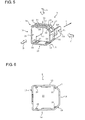
- FIG. 5 is a perspective view illustrating the intermediate member 5.
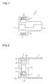
- FIG. 6 is a front view illustrating the intermediate member 5 shown in FIG. 5 , when viewed in a direction D.
- FIG. 7 is a side view illustrating the intermediate member 5 shown in FIG. 5 , when viewed in a direction F.
- FIG. 8 is a plan view illustrating the intermediate member 5 shown in FIG. 5 , when viewed in a direction G.
- the intermediate member 5 is formed by punching and bending the metal plate and by combining protrusion joining parts 5M and 5M.
- the intermediate member 5 includes a frame 10 with a substantially rectangular cross-section and extension parts 11.
- the frame 10 includes side surface parts 12, 13, 14, 15, 16, and 17. Hole parts 18, 19, 20, 21, and 22 are formed in the side surface parts 17, 12, and 13. A hole part 23 is formed in the side surface parts 13 and 14. A hole part 24 is formed in the side surface parts 14, 15, and 16.
- the frame 10 includes plural spring parts 26 to be fixed by the elastic force to the holder member 61 shown in FIG. 1 .
- the spring parts 26 protrude toward the inside of the frame 10.
- the holder member 61 passes through an opening part 25 formed in the frame 10.
- the extension parts 11 protrude from the side surface parts 13 and 16 in the direction T and extend in parallel.
- the optical connector includes the plastic ferrule holding the optical fibers, the plastic holder member holding the ferrule, the plastic plug arranged outside the holder member, and the metal intermediate member arranged between the outer surface of the holder member and the inner surface of the holder member.
- the ferrule holds the optical fiber core wires of the multi-core fiber tape core wire.
- the intermediate member is a metal frame formed by bending a metal plate.
- the intermediate member can be formed with high precision by simply bending the metal plate.
- connection end faces of the multi-core optical fiber core wires 7 of the male optical connector 1 are optically connected to the connection end faces of the multi-core optical fiber core wires 7 of the male optical connector 51.
- the multi-core optical fiber core wires 7 of the male optical connector 1 may be connected to an adapter (not shown), or the multi-core optical fiber core wires 7 of the male optical connector 51 may be connected to an adapter (not shown).
- the ferrule holds the multi-core optical fiber core wires, but the ferrule may hold a single-core optical fiber core wire.
Landscapes
- Physics & Mathematics (AREA)
- General Physics & Mathematics (AREA)
- Optics & Photonics (AREA)
- Mechanical Coupling Of Light Guides (AREA)
Abstract
Description
- The present invention relates to an optical connector, and more particularly, to an optical connector in which a part of a housing of the optical connector is formed of a metal part.
- With diversification and large capacity of communication, communication using an optical fiber such as FTTH (Fiber To The Home) has been rapidly spread. The optical fibers are connected to each other using an optical connector.
Constituent elements of a housing of the optical connector are made of plastic by injection molding and include a plastic ferrule, a holder member covering the plastic ferrule, a plastic intermediate member covering the holder member, and a plug arranged around the intermediate member.
A related technology of this kind of optical connector is disclosed inPatent Document 1. - Patent Document 1: Japanese Patent Application Laid-Open (JP-A) No.
63-239407 - In the technology disclosed in
Patent Document 1, however, in order to further reduce or increase the size of a unit of the ferrule and the holder member of the optical connector without modifying the size of the plug, the shape of the plastic intermediate member have to be modified to match with the reduced or increased size of the unit of the ferrule and the holder member. If the plastic intermediate member is thinned, the plastic intermediate member may be readily warped or distorted and the strength of the intermediate member may become weaker, thereby causing shape accuracy of the intermediate member to be low. - If the plastic intermediate member is warped or distorted, there is a possibility that a problem arises in fitting the unit of the ferrule and the holder member, the intermediate member, and the plug to one another when the unit of the ferrule and the holder member, the intermediate member, and the plug are assembled. Therefore, working efficiency may deteriorate when the units of the ferrule and the holder member, the intermediate member, and the plug are assembled.
Accordingly, to solve the above-mentioned problems, an object of the invention is to provide an optical fiber that can be readily assembled by forming an intermediate member of metal to ensure the strength of the intermediate member, even though the intermediate member is thinned. - In order to solve the above-mentioned problems, an optical connector according to the present invention connects optical fibers to each other and includes: a plastic ferrule that holds the optical fibers; a plastic holder member that holds the ferrule; a plastic plug that is arranged outside the holder member; and a metal intermediate member that is disposed between an outer surface of the holder member and an inner surface of the plug.
- In the optical connector of the present invention, the ferrule may hold an optical fiber core wire of a multi-core fiber tape core wire.
In the optical connector of the present invention, the intermediate member may be formed by bending a metal plate. - According to the present invention, an optical connector can readily be assembled by forming an intermediate member of metal to ensure the strength of the intermediate member, even though the intermediate member is thinned.
-
-
FIG. 1 is a perspective view illustrating a male optical connector according to a preferred embodiment of an optical connector of the invention. -
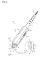
FIG. 2 is a perspective view illustrating a female optical connector according to a preferred embodiment an optical connector of the invention. -
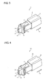
FIG. 3 is a perspective view illustrating a state where a plug of the male optical connector shown inFIG. 1 is shifted. -
FIG. 4 is a perspective view illustrating a state where a plug of the female optical connector shown inFIG. 2 is shifted. -
FIG. 5 is a perspective view illustrating an intermediate member. -
FIG. 6 is a front view illustrating the intermediate member shown inFIG. 5 , when viewed in a direction D. -
FIG. 7 is a side view illustrating the intermediate member shown inFIG. 6 , when viewed in a direction F. -
FIG. 8 is a plan view illustrating the intermediate member shown inFIG. 7 , when viewed in a direction G. -
- 1:
- optical connector
- 2:
- housing
- 3:
- boot
- 4:
- ferrule
- 5:
- intermediate member
- 6:
- plug
- 7:
- optical fiber core wire
- 8:
- multi-core fiber tape core wire
- 9:
- guide pin
- 10:
- frame
- 61:
- holder member
- Hereinafter, preferred embodiments of the present invention will be described in detail with reference to the drawings.
-
FIGS. 1 and2 are perspective views illustrating optical connectors according to a preferred embodiment of the invention. An exemplary male optical connector is shown inFIG. 1 and an exemplary female optical connector to be connected to the male optical connector shown inFIG. 1 is shown inFIG. 2 . -
FIG. 3 is a perspective view illustrating a state where anintermediate member 5 and aholder member 61 are exposed by slightly shifting aplug 6 of the maleoptical connector 1 shown inFIG. 1 in a direction T1.FIG. 4 is a perspective view illustrating a state where anintermediate member 5 and aholder member 61 are exposed by slightly shifting aplug 56 of the femaleoptical connector 51 shown inFIG. 2 in a direction T1. - First, the configuration of the male
optical connector 1 will be described with reference toFIGS. 1 and3 .
As shown inFIG. 1 , the maleoptical connector 1 includes ahousing 2 and a boot 3 made of flexible plastic and led out from thehousing 2. The boot 3 holds a multi-core fibertape core wire 8. Thehousing 2 includes aferrule 4, aplastic holder member 61 that covers the outer surface of theferrule 4, theintermediate member 5 that is arranged on the outer surface of theholder member 61, and theplastic plug 6 that is arranged to cover the outer surface of thehold member 61 and the outer surface of theintermediate member 5 and is slidable relative to theholder member 61 and theintermediate member 5. - The
ferrule 4 shown inFIGS. 1 and3 is made of plastic by injection molding. On aferrule end face 27 of theferrule 4, connection end faces of plural opticalfiber core wires 7 of the multi-core fibertape core wire 8 are arranged in series in a direction L. On both sides of the plural opticalfiber core wires 7, twoguide pins 9 are disposed in parallel with protruding from theferrule end face 27 in a direction S. - As shown in
FIGS. 1 and3 , theplastic holder member 61 is arranged on the outer surface of theferrule 4 and theintermediate member 5 is further arranged in a tip end of the outer surface of theholder member 61. Theholder member 61 holds theferrule 4 so as to cover the outer surface thereof, and theintermediate member 5 is arranged between the outer surface of theholder member 61 and the inner surface of thehousing 2. Theintermediate member 5 is fixed to the outer surface of theholder member 61 by the elastic force, for example.
Theintermediate member 5 is formed of not plastic but metal. Theintermediate member 5 is formed by bending a metal plate. Examples of the metal material of theintermediate member 5 include iron, aluminum, and brass, but the invention is not particularly limited thereto. - The
plug 6 covers the outer surface of theintermediate member 5, as shown inFIG. 1 , and can slide against an urging force of a spring (not shown) in the direction T along a guide rail formed in theholder member 61, for example. Theplug 6 has a spatial part with a substantially rectangular cross-section surface. Agripping part 26 is formed in the middle portion of the plug. - Next, the configuration of the female
optical connector 51 will be described with reference toFIGS. 2 and4 .
As shown inFIG. 2 , the femaleoptical connector 51 includes ahousing 52 and aboot 53 made of flexible plastic and led out from thehousing 52. Theboot 53 holds a multi-core fibertape core wire 8. Thehousing 52 includes aferrule 54, aplastic holder member 61 that covers the outer surface of theferrule 54, theintermediate member 5 that is arranged on the outer surface of theholder member 61, and theplastic plug 56 that is arranged to cover the outer surface of thehold member 61 and the outer surface of theintermediate member 5 and is slidable relative to theholder member 61 and theintermediate member 5. - The
ferrule 54 shown inFIGS. 2 and4 is made of plastic by injection molding. On a ferrule end face 77 of theferrule 54, connection end faces of plural opticalfiber core wires 7 of the multi-core fibertape core wire 8 are arranged in series in the direction L. On theferrule end face 77, guide holes 66 are formed in the direction S on both sides of the multi-core opticalfiber core wires 7. - As shown in
FIGS. 2 and4 , theholder member 61 and theintermediate member 5 are arranged outside theferrule 54. Theintermediate member 5 is the same member as theintermediate member 5 of the above-described maleoptical connector 1 and is formed of not plastic but metal. Examples of the metal material of theintermediate member 5 include iron, aluminum, and brass, but the invention is not particularly limited thereto. As theintermediate member 5 of the femaleoptical connector 51, the same member as theintermediate member 5 of the maleoptical connector 1 may be used. Theintermediate member 5 is fixed to the outer surface of theholder member 61 by the elastic force, for example. - The
plug 56 covers the outer surface of theintermediate member 5, as shown inFIG. 2 , and can slide against an urging force of a spring (not shown) in the direction T along a guide rail formed in theholder member 61, for example. Theplug 56 has a spatial part with a substantially rectangular cross-section surface. Agripping part 86 is formed in the middle portion of the plug. - When the connection end faces of the multi-core optical
fiber core wires 7 of the maleoptical connector 1 shown inFIG. 1 are optically connected to the connection end faces of the multi-core opticalfiber core wires 7 of the femaleoptical connector 51, the guide pins 9 and 9 of the maleoptical connector 1 are respectively inserted into the guide holes 66 and 66 of the femaleoptical connector 51 for positioning. - An exemplary configuration of the
intermediate member 5 will be described with reference toFIGS. 5 to 8 .
FIG. 5 is a perspective view illustrating theintermediate member 5.FIG. 6 is a front view illustrating theintermediate member 5 shown inFIG. 5 , when viewed in a direction D.FIG. 7 is a side view illustrating theintermediate member 5 shown inFIG. 5 , when viewed in a direction F.FIG. 8 is a plan view illustrating theintermediate member 5 shown inFIG. 5 , when viewed in a direction G. - As shown in
FIGS. 5 to 8 , theintermediate member 5 is formed by punching and bending the metal plate and by combiningprotrusion joining parts intermediate member 5 includes aframe 10 with a substantially rectangular cross-section andextension parts 11.
Theframe 10 includesside surface parts Hole parts side surface parts hole part 23 is formed in theside surface parts hole part 24 is formed in theside surface parts - The
frame 10 includesplural spring parts 26 to be fixed by the elastic force to theholder member 61 shown inFIG. 1 . Thespring parts 26 protrude toward the inside of theframe 10. As shown inFIGS. 3 and 4 , theholder member 61 passes through anopening part 25 formed in theframe 10. Theextension parts 11 protrude from theside surface parts
By holding thegripping parts optical connector 1 into the guide holes 66 and 66 of theoptical connector 51, the multi-corefiber core wires 7 of theoptical connector 1 shown inFIG. 1 and theoptical connector 51 shown inFIG. 2 can be reliably connected to each other. - According to the embodiment of the invention, the optical connector includes the plastic ferrule holding the optical fibers, the plastic holder member holding the ferrule, the plastic plug arranged outside the holder member, and the metal intermediate member arranged between the outer surface of the holder member and the inner surface of the holder member.
Thus, even when the intermediate member is configured to be thinned, by forming the intermediate member of metal, the strength of the intermediate member can be ensured. Therefore, since the metal intermediate member is warped or distorted less than a plastic intermediate member, the ferrule, the intermediate member, and the plug can be readily assembled.
Even when ferrules with different sizes are used, the size of the intermediate member has only to be changed without modifying the shape of the plug. - The ferrule holds the optical fiber core wires of the multi-core fiber tape core wire. With such a configuration, the optical connector holding the multi-core fiber core wire can be readily assembled.
The intermediate member is a metal frame formed by bending a metal plate. Thus, the intermediate member can be formed with high precision by simply bending the metal plate. - The invention is not limited to the above-described embodiment, but may be modified in various forms.
For example, in the above-described embodiment, the connection end faces of the multi-core opticalfiber core wires 7 of the maleoptical connector 1 are optically connected to the connection end faces of the multi-core opticalfiber core wires 7 of the maleoptical connector 51.
However, the multi-core opticalfiber core wires 7 of the maleoptical connector 1 may be connected to an adapter (not shown), or the multi-core opticalfiber core wires 7 of the maleoptical connector 51 may be connected to an adapter (not shown).
The ferrule holds the multi-core optical fiber core wires, but the ferrule may hold a single-core optical fiber core wire.
Claims (3)
- An optical connector that connects optical fibers to each other, comprising:a plastic ferrule that holds the optical fibers;a plastic holder member that holds the ferrule;a plastic plug that is arranged outside the holder member; anda metal intermediate member that is disposed between an outer surface of the holder member and an inner surface of the plug.
- The optical connector according to claim 1,
wherein the ferrule holds an optical fiber core wire of a multi-core fiber tape core wire. - The optical connector according to claim 1 or 2,
wherein the intermediate member is formed by bending a metal plate.
Applications Claiming Priority (2)
| Application Number | Priority Date | Filing Date | Title |
|---|---|---|---|
| JP2008068769 | 2008-03-18 | ||
| PCT/JP2009/054021 WO2009116389A1 (en) | 2008-03-18 | 2009-03-04 | Optical connector |
Publications (2)
| Publication Number | Publication Date |
|---|---|
| EP2256529A1 true EP2256529A1 (en) | 2010-12-01 |
| EP2256529A4 EP2256529A4 (en) | 2013-06-19 |
Family
ID=41090795
Family Applications (1)
| Application Number | Title | Priority Date | Filing Date |
|---|---|---|---|
| EP09721838.2A Withdrawn EP2256529A4 (en) | 2008-03-18 | 2009-03-04 | Optical connector |
Country Status (5)
| Country | Link |
|---|---|
| US (1) | US8297851B2 (en) |
| EP (1) | EP2256529A4 (en) |
| JP (1) | JP5041452B2 (en) |
| CN (1) | CN101971067A (en) |
| WO (1) | WO2009116389A1 (en) |
Families Citing this family (1)
| Publication number | Priority date | Publication date | Assignee | Title |
|---|---|---|---|---|
| JP5041452B2 (en) * | 2008-03-18 | 2012-10-03 | 古河電気工業株式会社 | Optical connector |
Family Cites Families (15)
| Publication number | Priority date | Publication date | Assignee | Title |
|---|---|---|---|---|
| JPS60198509A (en) * | 1984-03-22 | 1985-10-08 | Sumitomo Electric Ind Ltd | Optical connector ferrule and its production |
| JP2567390B2 (en) | 1987-03-27 | 1996-12-25 | 日本電信電話株式会社 | Optical connector |
| US5390270A (en) * | 1989-11-28 | 1995-02-14 | Kel Corporation | Optical fiber ferrule assemblies |
| JPH0694940A (en) | 1992-09-14 | 1994-04-08 | Hitachi Cable Ltd | Waveguide-type optical module |
| JPH08262270A (en) | 1995-03-24 | 1996-10-11 | Hirose Electric Co Ltd | Optical fiber connector and tools used therefor |
| US6081647A (en) * | 1998-01-05 | 2000-06-27 | Molex Incorporated | Fiber optic connector receptacle |
| US6079881A (en) * | 1998-04-08 | 2000-06-27 | Molex Incorporated | Fiber optic connector receptacle assembly |
| JP3318264B2 (en) | 1998-08-03 | 2002-08-26 | 日本電信電話株式会社 | Optical connector |
| JP4028354B2 (en) * | 2002-10-01 | 2007-12-26 | 株式会社フジクラ | Optical connector with shutter |
| JP2007133368A (en) | 2005-10-14 | 2007-05-31 | Yazaki Corp | Ferrule tip protection structure for optical connectors |
| JP4942327B2 (en) * | 2005-10-28 | 2012-05-30 | スリーエム イノベイティブ プロパティズ カンパニー | Optical connector |
| US7211739B1 (en) * | 2006-03-27 | 2007-05-01 | Emc Corporation | Electromagnetic interference (EMI) shield for a cable-bulkhead interface |
| JP5069015B2 (en) | 2007-02-02 | 2012-11-07 | スリーエム イノベイティブ プロパティズ カンパニー | Optical connector |
| JP5041452B2 (en) * | 2008-03-18 | 2012-10-03 | 古河電気工業株式会社 | Optical connector |
| US7841778B2 (en) * | 2008-12-19 | 2010-11-30 | The Furukawa Electric Co., Ltd. | Optical connector |
-
2009
- 2009-03-04 JP JP2010503823A patent/JP5041452B2/en not_active Expired - Fee Related
- 2009-03-04 CN CN2009801091452A patent/CN101971067A/en active Pending
- 2009-03-04 US US12/933,266 patent/US8297851B2/en active Active
- 2009-03-04 WO PCT/JP2009/054021 patent/WO2009116389A1/en not_active Ceased
- 2009-03-04 EP EP09721838.2A patent/EP2256529A4/en not_active Withdrawn
Also Published As
| Publication number | Publication date |
|---|---|
| JPWO2009116389A1 (en) | 2011-07-21 |
| JP5041452B2 (en) | 2012-10-03 |
| WO2009116389A1 (en) | 2009-09-24 |
| EP2256529A4 (en) | 2013-06-19 |
| CN101971067A (en) | 2011-02-09 |
| US8297851B2 (en) | 2012-10-30 |
| US20110044586A1 (en) | 2011-02-24 |
Similar Documents
| Publication | Publication Date | Title |
|---|---|---|
| US9459412B2 (en) | Optical connector receptacle, receptacle housing, optical connector adapter, and adapter housing | |
| US8118495B2 (en) | Method of assembling an optical connector and an optical connector | |
| EP3176617B1 (en) | Boot for optical connector ferrule | |
| CN100388028C (en) | Connector Assembly Clips | |
| EP1887395A1 (en) | Optical connector | |
| US8406588B2 (en) | Optical connector and method of connecting fiber array | |
| US20130077921A1 (en) | Optical-electrical connector having a resilient member for urging ferrule against lens member | |
| US11650380B2 (en) | Fiber connector assembly | |
| CN102033269A (en) | Adapter system | |
| CN104216060A (en) | MT (mechanical transfer) contact and optical connector with same | |
| EP3201666A1 (en) | Ferrule for multi-fiber optical connector | |
| EP1182477A1 (en) | Optical connector housing, optical connector using the optical connector housing and connection structure between optical connector and optical component using the optical connector housing | |
| US7641397B2 (en) | Optical connector | |
| EP3287824A1 (en) | Multi-core optical connector | |
| US8157455B2 (en) | Optical connector | |
| US8297851B2 (en) | Optical connector | |
| CN101589323B (en) | Optical connector | |
| JP2014501398A (en) | Optical fiber connector | |
| CN115220157A (en) | an active optical cable | |
| US8425127B2 (en) | Optical fiber coupling connector | |
| CN210666107U (en) | Ferrule and optical fiber connector | |
| US20180348444A1 (en) | Optical connector | |
| CN116349094A (en) | Connector | |
| CN222213008U (en) | SC type MPO multicore fiber connector | |
| JP5291062B2 (en) | Manufacturing method of optical connector |
Legal Events
| Date | Code | Title | Description |
|---|---|---|---|
| PUAI | Public reference made under article 153(3) epc to a published international application that has entered the european phase |
Free format text: ORIGINAL CODE: 0009012 |
|
| 17P | Request for examination filed |
Effective date: 20100923 |
|
| AK | Designated contracting states |
Kind code of ref document: A1 Designated state(s): AT BE BG CH CY CZ DE DK EE ES FI FR GB GR HR HU IE IS IT LI LT LU LV MC MK MT NL NO PL PT RO SE SI SK TR |
|
| AX | Request for extension of the european patent |
Extension state: AL BA RS |
|
| RIN1 | Information on inventor provided before grant (corrected) |
Inventor name: NISHIMURA, NAOYA Inventor name: MIYAZAKI, HIDEKI |
|
| DAX | Request for extension of the european patent (deleted) | ||
| RIC1 | Information provided on ipc code assigned before grant |
Ipc: G02B 6/38 20060101ALI20130419BHEP Ipc: G02B 6/36 20060101AFI20130419BHEP |
|
| RIC1 | Information provided on ipc code assigned before grant |
Ipc: G02B 6/36 20060101AFI20130502BHEP Ipc: G02B 6/38 20060101ALI20130502BHEP |
|
| RIC1 | Information provided on ipc code assigned before grant |
Ipc: G02B 6/36 20060101AFI20130507BHEP Ipc: G02B 6/38 20060101ALI20130507BHEP |
|
| A4 | Supplementary search report drawn up and despatched |
Effective date: 20130522 |
|
| RIC1 | Information provided on ipc code assigned before grant |
Ipc: G02B 6/36 20060101AFI20130515BHEP Ipc: G02B 6/38 20060101ALI20130515BHEP |
|
| GRAP | Despatch of communication of intention to grant a patent |
Free format text: ORIGINAL CODE: EPIDOSNIGR1 |
|
| INTG | Intention to grant announced |
Effective date: 20160705 |
|
| STAA | Information on the status of an ep patent application or granted ep patent |
Free format text: STATUS: GRANT OF PATENT IS INTENDED |
|
| STAA | Information on the status of an ep patent application or granted ep patent |
Free format text: STATUS: THE APPLICATION IS DEEMED TO BE WITHDRAWN |
|
| 18D | Application deemed to be withdrawn |
Effective date: 20161116 |