EP1887395A1 - Optical connector - Google Patents
Optical connector Download PDFInfo
- Publication number
- EP1887395A1 EP1887395A1 EP07103086A EP07103086A EP1887395A1 EP 1887395 A1 EP1887395 A1 EP 1887395A1 EP 07103086 A EP07103086 A EP 07103086A EP 07103086 A EP07103086 A EP 07103086A EP 1887395 A1 EP1887395 A1 EP 1887395A1
- Authority
- EP
- European Patent Office
- Prior art keywords
- optical connector
- waveguide
- optical
- connector
- lenses
- Prior art date
- Legal status (The legal status is an assumption and is not a legal conclusion. Google has not performed a legal analysis and makes no representation as to the accuracy of the status listed.)
- Granted
Links
- 230000003287 optical effect Effects 0.000 title claims abstract description 205
- 230000005540 biological transmission Effects 0.000 claims description 32
- 239000011347 resin Substances 0.000 claims description 25
- 229920005989 resin Polymers 0.000 claims description 25
- 238000006243 chemical reaction Methods 0.000 claims description 12
- 238000003491 array Methods 0.000 description 16
- 239000000835 fiber Substances 0.000 description 11
- 239000013307 optical fiber Substances 0.000 description 7
- 238000004891 communication Methods 0.000 description 5
- 238000000034 method Methods 0.000 description 4
- 238000000465 moulding Methods 0.000 description 3
- 238000010586 diagram Methods 0.000 description 2
- 230000003247 decreasing effect Effects 0.000 description 1
- 238000009792 diffusion process Methods 0.000 description 1
- 238000000605 extraction Methods 0.000 description 1
- 238000003780 insertion Methods 0.000 description 1
- 230000037431 insertion Effects 0.000 description 1
- 238000012986 modification Methods 0.000 description 1
- 230000004048 modification Effects 0.000 description 1
Images


Classifications
-
- G—PHYSICS
- G02—OPTICS
- G02B—OPTICAL ELEMENTS, SYSTEMS OR APPARATUS
- G02B6/00—Light guides; Structural details of arrangements comprising light guides and other optical elements, e.g. couplings
- G02B6/24—Coupling light guides
- G02B6/36—Mechanical coupling means
- G02B6/38—Mechanical coupling means having fibre to fibre mating means
- G02B6/3807—Dismountable connectors, i.e. comprising plugs
- G02B6/381—Dismountable connectors, i.e. comprising plugs of the ferrule type, e.g. fibre ends embedded in ferrules, connecting a pair of fibres
- G02B6/3825—Dismountable connectors, i.e. comprising plugs of the ferrule type, e.g. fibre ends embedded in ferrules, connecting a pair of fibres with an intermediate part, e.g. adapter, receptacle, linking two plugs
-
- G—PHYSICS
- G02—OPTICS
- G02B—OPTICAL ELEMENTS, SYSTEMS OR APPARATUS
- G02B6/00—Light guides; Structural details of arrangements comprising light guides and other optical elements, e.g. couplings
- G02B6/24—Coupling light guides
- G02B6/36—Mechanical coupling means
- G02B6/38—Mechanical coupling means having fibre to fibre mating means
- G02B6/3807—Dismountable connectors, i.e. comprising plugs
- G02B6/3873—Connectors using guide surfaces for aligning ferrule ends, e.g. tubes, sleeves, V-grooves, rods, pins, balls
- G02B6/3874—Connectors using guide surfaces for aligning ferrule ends, e.g. tubes, sleeves, V-grooves, rods, pins, balls using tubes, sleeves to align ferrules
- G02B6/3878—Connectors using guide surfaces for aligning ferrule ends, e.g. tubes, sleeves, V-grooves, rods, pins, balls using tubes, sleeves to align ferrules comprising a plurality of ferrules, branching and break-out means
- G02B6/3879—Linking of individual connector plugs to an overconnector, e.g. using clamps, clips, common housings comprising several individual connector plugs
-
- G—PHYSICS
- G02—OPTICS
- G02B—OPTICAL ELEMENTS, SYSTEMS OR APPARATUS
- G02B6/00—Light guides; Structural details of arrangements comprising light guides and other optical elements, e.g. couplings
- G02B6/24—Coupling light guides
- G02B6/36—Mechanical coupling means
- G02B6/38—Mechanical coupling means having fibre to fibre mating means
- G02B6/3807—Dismountable connectors, i.e. comprising plugs
- G02B6/3873—Connectors using guide surfaces for aligning ferrule ends, e.g. tubes, sleeves, V-grooves, rods, pins, balls
- G02B6/3885—Multicore or multichannel optical connectors, i.e. one single ferrule containing more than one fibre, e.g. ribbon type
-
- G—PHYSICS
- G02—OPTICS
- G02B—OPTICAL ELEMENTS, SYSTEMS OR APPARATUS
- G02B6/00—Light guides; Structural details of arrangements comprising light guides and other optical elements, e.g. couplings
- G02B6/24—Coupling light guides
- G02B6/42—Coupling light guides with opto-electronic elements
- G02B6/4201—Packages, e.g. shape, construction, internal or external details
- G02B6/4249—Packages, e.g. shape, construction, internal or external details comprising arrays of active devices and fibres
-
- G—PHYSICS
- G02—OPTICS
- G02B—OPTICAL ELEMENTS, SYSTEMS OR APPARATUS
- G02B6/00—Light guides; Structural details of arrangements comprising light guides and other optical elements, e.g. couplings
- G02B6/24—Coupling light guides
- G02B6/42—Coupling light guides with opto-electronic elements
- G02B6/4292—Coupling light guides with opto-electronic elements the light guide being disconnectable from the opto-electronic element, e.g. mutually self aligning arrangements
-
- G—PHYSICS
- G02—OPTICS
- G02B—OPTICAL ELEMENTS, SYSTEMS OR APPARATUS
- G02B6/00—Light guides; Structural details of arrangements comprising light guides and other optical elements, e.g. couplings
- G02B6/24—Coupling light guides
- G02B6/42—Coupling light guides with opto-electronic elements
- G02B6/4201—Packages, e.g. shape, construction, internal or external details
- G02B6/4204—Packages, e.g. shape, construction, internal or external details the coupling comprising intermediate optical elements, e.g. lenses, holograms
- G02B6/4214—Packages, e.g. shape, construction, internal or external details the coupling comprising intermediate optical elements, e.g. lenses, holograms the intermediate optical element having redirecting reflective means, e.g. mirrors, prisms for deflecting the radiation from horizontal to down- or upward direction toward a device
-
- G—PHYSICS
- G02—OPTICS
- G02B—OPTICAL ELEMENTS, SYSTEMS OR APPARATUS
- G02B6/00—Light guides; Structural details of arrangements comprising light guides and other optical elements, e.g. couplings
- G02B6/24—Coupling light guides
- G02B6/42—Coupling light guides with opto-electronic elements
- G02B6/4201—Packages, e.g. shape, construction, internal or external details
- G02B6/4246—Bidirectionally operating package structures
Definitions
- the present invention generally relates to an optical connector which is connected to an optical transmission line.
- a conventional optical connector has been physically connected to the optical transmission line.
- the ferrules of optical fibers In order to decrease loss at the connection position, the ferrules of optical fibers must be pressed by a force of approximately 10 N.
- a plug frame which holds the optical transmission line becomes large and the optical transmission line cannot be uniformly pressed.
- force of at least 10 N is required in each optical transmission line, a force more than 10 N needs to be applied.
- the present invention may provide an optical connector into which an optical transmission line can be easily inserted or from which the optical transmission line can be easily extracted.
- an optical connector includes a first waveguide member that includes a first waveguide, a first lens disposed at one end surface of the first waveguide, and a second lens disposed at the other end surface of the first waveguide.
- the optical connector further includes a case which contains the first waveguide member and into which case a second optical connector is engaged.
- plural first waveguide members are contained in the case and the case includes engaging sections into which plugs of the second optical connector are engaged.
- the first waveguide member includes plural first waveguides, plural first lenses, and plural second lenses.
- an angle exists between one end direction of the first waveguide and the other end direction of the first waveguide in the first waveguide member.
- the optical connector further includes a printed circuit board on which the first waveguide member is mounted, and photoelectric conversion elements for executing photoelectric conversion.
- the first lens is formed on the one end surface of the first waveguide and the second lens is formed on the other end surface of the first waveguide in the plural first waveguide members.
- the first waveguide is formed in the first waveguide member by forming a groove in transparent resin having a first refractive index, supplying transparent resin having a second refractive index in the groove, and covering the groove with a resin film.
- the photoelectric conversion elements are disposed to face the first lenses disposed at one of the end surfaces of the first waveguide in the first waveguide member and an optical transmission line is connected to face the second lens disposed at another of the end surfaces of the first waveguide in the second waveguide member.
- one of the first lenses is disposed to face one of the photoelectric conversion elements and the other of the first lenses is disposed to face the other of the photoelectric conversion elements.
- the first waveguide member includes convex sections to position the photoelectric conversion elements at positions corresponding to the focal length of the first lenses.
- the optical transmission line is disposed to face the second lens at a distance corresponding to the focal length of the second lens.
- the first and second lenses are integrally formed with the first waveguide member.
- the second lens in the optical connector faces a lens in the third optical connector which includes a second waveguide member.
- the fourth optical connector includes a third waveguide member that includes a third waveguide and third lenses each of which lenses is disposed at the corresponding end surfaces of the third waveguide member, and when the fourth optical connector is connected to the optical connector, the third lens faces the second lens of the optical connector.
- the fifth optical connector includes a fourth waveguide member which includes a fourth waveguide and fourth lenses each of which lenses is disposed at the corresponding end surfaces of the fourth waveguide, and when the fifth optical connector is connected to an optical transmission line, the fourth lens faces an end surface of the optical transmission line.
- an optical connector is formed by using a waveguide member that includes a waveguide, a first lens disposed at one end surface of the waveguide, and a second lens disposed at the other end surface of the waveguide. Therefore, when an optical transmission line is connected to the optical connector, it is not needed to press an end surface of the optical transmission line. That is, the inserting force of the optical transmission line into the optical connector and the extracting force thereof from the optical connector are low. With this, insertion or extraction of the optical transmission line is easy.
- the structure of the optical connector is simple. Especially, when the optical transmission line is formed of a multi-mode fiber, the optical transmission line can be easily inserted into the optical connector and extracted therefrom. In addition, since the lenses condense light transmitting through the optical connector and the optical transmission line, the light loss can be decreased and the optical communications can be efficiently executed.
- Fig. 1 is a perspective view of optical connectors according to the first embodiment of the present invention.
- Fig. 2 is an exploded perspective view of an optical socket connector 100 shown in Fig. 1.
- the optical socket connector 100 is mounted on a printed circuit board 101, and an optical plug connector 200 is attached to the optical socket connector 100.
- Plural waveguide arrays (waveguide members) 111 are adhered on the printed circuit board 101 by resin and covered with a case 112. With this, the optical socket connector 100 is formed.
- the case 112 is secured to the printed circuit board 101 by screws 113.
- Guiding sections 121 and screw holes 122 are formed in the front surface of the case 112.
- the optical plug connector 200 engages (is inserted) into the guiding sections 121.
- the guiding sections 121 guide tips of optical fibers of the optical plug connector 200 to the corresponding waveguide arrays 111.
- Fig. 3 is a perspective view of the waveguide array 111.
- Fig. 4 is a diagram showing a structure of the waveguide array 111. In Fig. 4, (a) shows a side view, (b) shows a plan view, (c) shows a front view, (d) shows a back view, and (e) shows a bottom view.
- plural waveguides 132 are formed in a waveguide array main body 131.
- the waveguide 132 is curved so that the direction of one end of the waveguide 132 is approximately orthogonal to the direction of the other end thereof.
- the waveguide array main body 131 is formed of transparent resin by molding. Grooves 141 are formed in the surface of the waveguide array main body 131 so that the waveguides 132 are formed. Lenses 142 are disposed at positions where the grooves 141 are extended in the Z1 direction in the waveguide array main body 131 and lenses 143 are disposed at positions where the grooves 141 are extended in the X2 direction in the waveguide array main body 131.
- a concave section is formed in the bottom surface of the waveguide array main body 131, that is, in the Z1 direction.
- the upper surface of the waveguide array main body 131 has a part where an approximately cylinder-shaped surface (curved surface) is formed in the Z2 direction.
- the grooves 141 are formed in the curved surface. The curvature of the curved surface is determined so that light is not leaked to the outside when the waveguides 132 are formed.
- Resin whose refractive index is different from that of the waveguide array main body 131 is supplied into the grooves 141 and the resin is hardened; then the waveguide array main body 131 including the hardened resin is covered with a resin film 144 whose refractive index is almost the same as that of the waveguide array main body 131. With this, the waveguides 132 are formed.
- the one end of the waveguide 132 faces in a direction orthogonal to the printed circuit board 101, that is, in the Z1 direction, and the other end thereof faces in a direction parallel to the printed circuit board 101, that is, in the X2 direction.
- the cross-sectional shape of the groove 141 is almost a square with 50 ⁇ m sides in a multimode fiber, but is almost a square with 10 ⁇ m sides in a single-mode fiber.
- the shape of the convex section 145 is almost a semi-ball.
- the convex sections 145 contact the surface of the printed circuit board 101.
- the contacting area between the waveguide arrays 111 and the printed circuit board 101 can be as small as possible. Consequently, the waveguide arrays 111 can be smoothly slid on the printed circuit board 101. That is, the waveguide arrays 111 can be precisely positioned on the printed circuit board 101.
- the waveguide array main body 131 has a flange section 146 extending in the X1 direction.
- Fig. 5 is a perspective view showing the mounting method of the waveguide array 111 on the printed circuit board 101.
- a predetermined gap is formed between the printed circuit board 101 and the bottom surface of the waveguide array main body 131 including the flange section 146 by the convex sections 145. Resin is supplied in the gap.
- a driver IC 151, a light emitting element 152, a light receiving element 153, a receiver IC 154, and so on are mounted on the printed circuit board 101 under the waveguide array main body 131 including the flange section 146.
- the waveguide 132 has four lines
- the lens 142 has four lenses
- the lens 143 has four lenses.
- only one light emitting element 152 and only one light receiving element 153 are shown; however, actually, four light emitting elements 152 and four light receiving elements 153 are disposed corresponding to the number of the lenses 142.
- the lenses 142 are formed at the positions where the waveguides 132 are extended in the bottom surface of the waveguide array main body 131.
- the surface of the lenses 142 is spherical; one lens 142 is disposed to face the light emitting element 152 and the other lens 142 is disposed to face the light receiving element 153.
- the lens 142 condenses light emitted from the light emitting element 152 and inputs the condensed light to the end surface of the waveguide 132.
- the other lens 142 condenses light output from the end surface of the waveguide 132 on the light receiving element 153.
- the distance between the lens 142 and the light emitting element 152 or the light receiving element 153 is determined by the convex sections 145 corresponding to the focal length of the lens 142.
- the focal length is based on the refractive index of the waveguide array 111, the curvature of the lens 142, and so on.
- the lenses 143 are formed at the positions where the waveguides 132 are extended on the back surface of the waveguide array main body 131, that is, on the surface in the X2 direction of the waveguide array main body 131.
- the end surfaces of the optical transmission lines of the optical plug connector 200 face the lenses 143.
- Fig. 6 is a perspective view showing a positioning structure between the optical socket connector 100 and the optical plug connector 200.
- (a) is a view taken from the side of the optical plug connector 200
- (b) is a view taken from the side of the optical socket connector 100.
- holes 147 are formed in the back surface (X2 direction surface) of the waveguide array main body 131 at the side of the lenses 143. Pins 148 disposed at the end of the optical transmission line of the optical plug connector 200 are engaged into the holes 147. With this, the lenses 143 are positioned to face the end surface of the optical transmission line of the optical plug connector 200.
- the surface of the lens 143 is spherical and one lens 143 condenses light output from the end surface of the waveguide 132 on the end surface of the light transmission line of the optical plug connector 200. Further, the other lens 143 condenses light output form the end surface of the light transmission line of the optical plug connector 200 on the end surface of waveguide 132. At this time, the distance between the lens 143 and the end surface of the optical transmission line of the optical plug connector 200 is maintained at a predetermined distance corresponding to the focal length of the lens 143.
- the focal length is based on the refractive index of the waveguide array 111, the curvature of the lens 143, and so on.
- the waveguide array 111 Since the waveguide array 111 is used, light diffusion and light attenuation can be prevented without tightly pressing the optical plug connector 200 into the waveguide array 111. That is, optical communications can be efficiently executed.
- light output from the optical transmission line of the optical plug connector 200 can be led to the printed circuit board 101, and also light output from the printed circuit board 101 can be led to the optical transmission line of the optical plug connector 200.
- Fig. 7 is an exploded perspective view of the optical plug connector 200.
- a plug connector 212 is attached to the tip of the multi-core fiber cable 210, and the plural plug connectors 212 to which the corresponding tips of the multi-core fiber cables 210 are attached are maintained by a plug frame 211.
- the plug connector 212 is, for example, an MPO connector.
- the plug frame 211 is composed of an upper frame 221 and a lower frame 222. Each of the upper frame 221 and the lower frame 222 has engaging sections 223 for engaging the plug connectors 212.
- the upper frame 221 is secured to the lower frame 222 by screws 224.
- the plug connectors 212 are secured to the plug frame 211 by engaging the plug connectors 212 into the engaging sections 223. With this, the plural multi-core fiber cables 210 are integrated. The tips of the plug connectors 212 protrude from the plug frame 211 in the direction facing the optical socket connector 100.
- Screw holding sections 226 are formed near each end of the upper frame 221 and the lower frame 222. When screws 227 are securely held by the corresponding screw holding sections 226 and the upper frame 221 is secured to the lower frame 222 by the screws 224, the screws 227 are securely held in the screw holding sections 226.
- the screws 227 are rotatably held by the plug frame 211 in the arrow ⁇ direction. Similar to the tips of the plug connectors 212, the tips of the screws 227 protrude in the direction facing the optical socket connector 100.
- the tips of the plug connectors 212 of the optical plug connector 200 are inserted into the corresponding guiding sections 121 formed in the front surface of the case 112 of the optical socket connector 100. With this, the tips of the screws 227 face the corresponding screw holes 122 of the optical socket connector 100. When the screws 227 are threaded into the corresponding screw holes 122, the optical plug connector 200 is secured to the optical socket connector 100.
- the plug connectors 212 of the optical plug connector 200 there is no need for the plug connectors 212 of the optical plug connector 200 to be pressed by a high force to contact the corresponding waveguide arrays 111 of the optical socket connector 100. Therefore, the securing force generated by the screws 227 can be small. Consequently, inserting and extracting forces between the optical socket connector 100 and the optical plug connector 200 can be small and the optical plug connector 200 can be easily inserted into the optical socket connector 100 and easily extracted form the optical socket connector 100.
- the case 112 since the strength of the case 112 can be low, the case 112 can be formed of resin. Consequently, the cost of the optical socket connector 100 can be low and the weight thereof can be light.
- the optical socket connector 100 and the optical plug connector 200 using the multi-core fiber cables 210 can be realized.
- the light input direction to the waveguide array 111 is orthogonal to the light output direction from the waveguide array 111.
- the light input and output directions can be freely determined by adjusting the angle between the light input and output directions.
- Fig. 8 is a perspective view of optical connectors according to the second embodiment of the present invention.
- a same element as that shown in Fig. 1 has the same reference number and the same description is omitted.
- an optical plug connector 300 is used and is directly mounted on a printed circuit board 102, and the printed circuit board 102 is directly connected to the printed circuit board 101 on which the optical socket connector 100 is mounted.
- Fig. 9 is an exploded perspective view of the optical plug connector 300 according to the second embodiment of the present invention.
- the optical socket connector 300 includes waveguide arrays 311, plug frames 312, a case 313, screws 314, and screws 315.
- Fig. 10 is a perspective view of the waveguide array 311.
- a same element as that shown in Fig. 3 has the same reference number and the same description is omitted.
- one end of the waveguide 132 is extended in the Z1 direction, and the waveguide array 311 is mounted on the printed circuit board 102.
- the case 313 is composed of an upper case 313a and a lower case 313b. Each of the upper and lower cases 313a and 313b has engaging sections 321 and 322.
- the waveguide arrays 311 and the plug frames 312 are engaged in the corresponding engaging sections 321.
- the plug frame 312 is connected to the end of the waveguide array 311 in the X2 direction and is engaged into the engaging sections 321.
- the screws 314 are engaged into the corresponding engaging sections 322.
- the upper case 313a and the lower case 313b are secured by the screws 315. With this, the waveguide arrays 311 and the plug frames 312 are secured to the engaging sections 321, and the screws 314 are rotatably maintained in the corresponding engaging sections 322.
- the plug frames 312 protrude from the front surface of the case 313 in the direction facing the optical socket connector 100.
- the tips of the screws 314 protrude from the front surface of the case 313 in the direction facing the optical socket connector 100.
- Fig. 11 is a cut-away side view when the optical plug connector 300 is attached to the optical socket connector 100.
- the distance between the lens 143 of the waveguide array 311 and the lens 143 of the waveguide array 111 is maintained at a predetermined distance corresponding to the focal lengths of the lenses 143 facing each other.
- the focal length is determined based on the refractive indexes of the waveguide arrays 111 and 311, the curvature of the lens 143, and so on.
- the printed circuit board 101 can be directly connected to the printed circuit board 102 in the optical communications without using an optical fiber.
- Fig. 12 is a perspective view of optical connectors according to the third embodiment of the present invention.
- Fig. 13 is an exploded perspective view of an optical plug connector 400 shown in Fig. 12.
- a same element as that shown in Fig. 8 has the same reference number and the same description is omitted.
- the optical plug connector 400 is an adapter which connects the optical socket connector 100 mounted on the printed circuit board 101 with the optical socket connector 100 mounted on the printed circuit board 102. As shown in Fig. 13, the optical plug connector 400 includes plural waveguide arrays 411, plural plug frames 412, an upper case 413, and a lower case 414. In Fig. 13, two plug frames 412 are attached to the waveguide array 411.
- Fig. 14 is a perspective view of the waveguide array 411.
- the waveguide array 411 includes plural waveguides 422 formed in a waveguide array main body 421.
- the waveguide array main body 421 is formed of transparent resin by molding.
- the waveguide array main body 421 includes grooves 423 in which the waveguides 422 are formed and lenses 424 disposed at positions where the grooves 423 are formed at the side surfaces of the waveguide array main body 421.
- Resin whose refractive index is different from that of the waveguide array main body 421 is supplied into the grooves 423 and the resin is hardened; then the waveguide array main body 421 including the hardened resin is covered with a resin film 426 whose refractive index is almost the same as that of the waveguide array main body 421. With this, the waveguides 422 are formed.
- the waveguide 422 is formed in a straight-line shape in the X1 and X2 directions.
- the cross-sectional shape of the groove 423 is almost a square with 50 ⁇ m sides in a multimode fiber, but is almost a square with 10 ⁇ m sides in a single-mode fiber.
- the plug frames 412 are attached at both the ends of the waveguide array 411.
- Plural waveguide arrays 411 to which the plug frames 412 are attached are engaged into corresponding engaging sections 415 formed in the upper case 413 and the lower case 414. Then, the upper case 413 and the lower case 414 are secured to each other by screws 416.
- Fig. 15 is a cut-away side view when the optical plug connector 400 is attached to the optical socket connectors 100 on the printed circuit boards 101 and 102.
- the distance between the lens 424 of the waveguide array 411 and the lens 143 of the waveguide array 111 is maintained at a predetermined distance corresponding to the focal lengths of the lenses 143 and 424 facing each other.
- the optical socket connector 100 on the printed circuit board 101 can be connected with the optical socket connector 100 on the printed circuit board 102 by the optical plug connector 400.
- Fig. 16 is a cut-away side view of an optical connector 500 according to the fourth embodiment of the present invention.
- the optical connector 500 orthogonally bends light, that is, is a right angle type adapter.
- the optical connector 500 includes waveguide arrays 511, sockets 512, and a case 513.
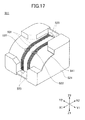
- Fig. 17 is a perspective view of the waveguide array 511.
- the waveguide array 511 includes waveguides 522 and lenses 523.
- the waveguide array main body 521 is formed of transparent resin by molding.
- Grooves 531 are formed in the surface of the waveguide array main body 521 so that the waveguides 522 are formed.
- Lenses 523 are formed at positions where the ends of the grooves 531 are extended.
- the waveguide array main body 521 has an opening section whose shape is approximately concave at the corner of the Z1 direction and the X1 direction.
- the upper surface above the opening section of the waveguide array main body 521 has a part in which an approximately cylinder-shaped surface (curved surface) is formed in the Z2 direction.
- the grooves 531 are formed in the curved surface. The curvature of the curved surface is selected so that light is not leaked to the outside when the waveguides 522 are formed.
- the waveguide array main body 521 including the hardened resin is covered with a resin film 541 whose refractive index is almost the same as that of the waveguide array main body 521. With this, the waveguides 522 are formed.
- the cross-sectional shape of the groove 531 is almost a square with 50 ⁇ m sides.
- a plug connector 600 is disposed at one end of an optical fiber cable 601 and is attached to the socket 512 of the optical connector 500. With this, the end surface of the optical fiber cable 601 is positioned to face the lens 523 formed in the waveguide array main body 521.
- Light input from the optical fiber cable 601 is condensed at the lens 523 and the condensed light is input to one end of the waveguide 522.
- the light input to the waveguide 522 is output from the other end of the waveguide 522.
- the light output from the other end of the waveguide 522 is condensed at another lens 523 and the condensed light is input to the end surface of another optical fiber cable 601 to which another plug connector 600 is attached, to which plug connector 600 another socket 512 of the optical connector 500 is attached.
- the right angle type adapter (the optical connector 500) can be realized.
- the optical plug connector 200 is secured (locked) to the optical socket connector 100 by threading the screws 227 into the screw holes 122.
- another locking method can be used.
- a latching mechanism can be used in which the locked status between the optical plug connector 200 and the optical socket connector 100 is unlocked by a lever.
- a mechanical linkage is used in which the optical plug connector 200 is detached from the optical socket connector 100 by using a lever.
Abstract
Description
- The present invention generally relates to an optical connector which is connected to an optical transmission line.
- Recently, communication capacity has been increased due to progress of optical communications; therefore, a multi-core fiber optical connector has become required.
- A conventional optical connector has been physically connected to the optical transmission line. In order to decrease loss at the connection position, the ferrules of optical fibers must be pressed by a force of approximately 10 N.
- That is, in the conventional optical connector, since the ferules must be pressed by high force, inserting and extracting forces of the optical transmission line become large. Therefore, the optical transmission line cannot be easily inserted into or extracted from the optical connector.
- Especially, when a multi-core fiber is used, a plug frame which holds the optical transmission line becomes large and the optical transmission line cannot be uniformly pressed. When force of at least 10 N is required in each optical transmission line, a force more than 10 N needs to be applied.
- The present invention may provide an optical connector into which an optical transmission line can be easily inserted or from which the optical transmission line can be easily extracted.
- According to one aspect of the present invention, there is provided an optical connector. The optical connector includes a first waveguide member that includes a first waveguide, a first lens disposed at one end surface of the first waveguide, and a second lens disposed at the other end surface of the first waveguide.
- According to another aspect of the present invention, the optical connector further includes a case which contains the first waveguide member and into which case a second optical connector is engaged.
- According to another aspect of the present invention, plural first waveguide members are contained in the case and the case includes engaging sections into which plugs of the second optical connector are engaged.
- According to another aspect of the present invention, the first waveguide member includes plural first waveguides, plural first lenses, and plural second lenses.
- According to another aspect of the present invention, an angle exists between one end direction of the first waveguide and the other end direction of the first waveguide in the first waveguide member.
- According to another aspect of the present invention, the optical connector further includes a printed circuit board on which the first waveguide member is mounted, and photoelectric conversion elements for executing photoelectric conversion.
- According to another aspect of the present invention, the first lens is formed on the one end surface of the first waveguide and the second lens is formed on the other end surface of the first waveguide in the plural first waveguide members.
- According to another aspect of the present invention, the first waveguide is formed in the first waveguide member by forming a groove in transparent resin having a first refractive index, supplying transparent resin having a second refractive index in the groove, and covering the groove with a resin film.
- According to another aspect of the present invention, the photoelectric conversion elements are disposed to face the first lenses disposed at one of the end surfaces of the first waveguide in the first waveguide member and an optical transmission line is connected to face the second lens disposed at another of the end surfaces of the first waveguide in the second waveguide member.
- According to another aspect of the present invention, one of the first lenses is disposed to face one of the photoelectric conversion elements and the other of the first lenses is disposed to face the other of the photoelectric conversion elements.
- According to another aspect of the present invention, the first waveguide member includes convex sections to position the photoelectric conversion elements at positions corresponding to the focal length of the first lenses.
- According to another aspect of the present invention, the optical transmission line is disposed to face the second lens at a distance corresponding to the focal length of the second lens.
- According to another aspect of the present invention, the first and second lenses are integrally formed with the first waveguide member.
- According to another aspect of the present invention, when the optical connector is connected to a third optical connector, the second lens in the optical connector faces a lens in the third optical connector which includes a second waveguide member.
- According to another aspect of the present invention, there is provided a fourth optical connector. The fourth optical connector includes a third waveguide member that includes a third waveguide and third lenses each of which lenses is disposed at the corresponding end surfaces of the third waveguide member, and when the fourth optical connector is connected to the optical connector, the third lens faces the second lens of the optical connector.
- According to another aspect of the present invention, there is provided a fifth optical connector. The fifth optical connector includes a fourth waveguide member which includes a fourth waveguide and fourth lenses each of which lenses is disposed at the corresponding end surfaces of the fourth waveguide, and when the fifth optical connector is connected to an optical transmission line, the fourth lens faces an end surface of the optical transmission line.
- According to an embodiment of the present invention, an optical connector is formed by using a waveguide member that includes a waveguide, a first lens disposed at one end surface of the waveguide, and a second lens disposed at the other end surface of the waveguide. Therefore, when an optical transmission line is connected to the optical connector, it is not needed to press an end surface of the optical transmission line. That is, the inserting force of the optical transmission line into the optical connector and the extracting force thereof from the optical connector are low. With this, insertion or extraction of the optical transmission line is easy. In addition, the structure of the optical connector is simple. Especially, when the optical transmission line is formed of a multi-mode fiber, the optical transmission line can be easily inserted into the optical connector and extracted therefrom. In addition, since the lenses condense light transmitting through the optical connector and the optical transmission line, the light loss can be decreased and the optical communications can be efficiently executed.
- Features and advantages of the present invention will be apparent from the following detailed description when read in conjunction with the accompanying drawings.
-
- Fig. 1 is a perspective view of optical connectors according to a first embodiment of the present invention;
- Fig. 2 is an exploded perspective view of an
optical socket connector 100 shown in Fig. 1; - Fig. 3 is a perspective view of a waveguide array according to the first embodiment of the present invention;
- Fig. 4 is a diagram showing a structure of the waveguide array shown in Fig. 3;
- Fig. 5 is a perspective view showing a mounting method of the waveguide array on a printed circuit board;
- Fig. 6 is a perspective view showing a positioning structure between the optical socket connector and an optical plug connector;
- Fig. 7 is an exploded perspective view of the optical plug connector;
- Fig. 8 is a perspective view of optical connectors according to a second embodiment of the present invention;
- Fig. 9 is an exploded perspective view of an optical plug connector shown in Fig. 8;
- Fig. 10 is a perspective view of a waveguide array according to the second embodiment of the present invention;
- Fig. 11 is a cut-away side view when the optical plug connector shown is attached to the optical socket connector according to the second embodiment of the present invention;
- Fig. 12 is a perspective view of optical connectors according to a third embodiment of the present invention;
- Fig. 13 is an exploded perspective view of an optical plug connector shown in Fig. 12;
- Fig. 14 is a perspective view of a waveguide array in the optical plug connector shown in Fig. 12;
- Fig. 15 is a cut-away side view when the optical plug connector is attached to optical socket connectors on printed circuit boards according to the third embodiment of the present invention;
- Fig. 16 is a cut-away side view of an optical connector according to a fourth embodiment of the present invention; and
- Fig. 17 is a perspective view of a waveguide array shown in Fig. 16.
- Referring to the drawings, embodiments of the present invention are described.
- First, a first embodiment of the present invention is described.
- Fig. 1 is a perspective view of optical connectors according to the first embodiment of the present invention. Fig. 2 is an exploded perspective view of an
optical socket connector 100 shown in Fig. 1. - As shown in Figs. 1 and 2, the
optical socket connector 100 is mounted on a printedcircuit board 101, and anoptical plug connector 200 is attached to theoptical socket connector 100. Plural waveguide arrays (waveguide members) 111 are adhered on the printedcircuit board 101 by resin and covered with acase 112. With this, theoptical socket connector 100 is formed. Thecase 112 is secured to the printedcircuit board 101 byscrews 113. - Guiding
sections 121 and screwholes 122 are formed in the front surface of thecase 112. Theoptical plug connector 200 engages (is inserted) into the guidingsections 121. The guidingsections 121 guide tips of optical fibers of theoptical plug connector 200 to the correspondingwaveguide arrays 111. - Next, the
waveguide array 111 is described. - Fig. 3 is a perspective view of the
waveguide array 111. Fig. 4 is a diagram showing a structure of thewaveguide array 111. In Fig. 4, (a) shows a side view, (b) shows a plan view, (c) shows a front view, (d) shows a back view, and (e) shows a bottom view. - As shown in Figs. 3 and 4, in the
waveguide array 111,plural waveguides 132 are formed in a waveguide arraymain body 131. Thewaveguide 132 is curved so that the direction of one end of thewaveguide 132 is approximately orthogonal to the direction of the other end thereof. - The waveguide array
main body 131 is formed of transparent resin by molding.Grooves 141 are formed in the surface of the waveguide arraymain body 131 so that thewaveguides 132 are formed.Lenses 142 are disposed at positions where thegrooves 141 are extended in the Z1 direction in the waveguide arraymain body 131 andlenses 143 are disposed at positions where thegrooves 141 are extended in the X2 direction in the waveguide arraymain body 131. - In the bottom surface of the waveguide array
main body 131, that is, in the Z1 direction, a concave section is formed. The upper surface of the waveguide arraymain body 131 has a part where an approximately cylinder-shaped surface (curved surface) is formed in the Z2 direction. Thegrooves 141 are formed in the curved surface. The curvature of the curved surface is determined so that light is not leaked to the outside when thewaveguides 132 are formed. - Resin whose refractive index is different from that of the waveguide array
main body 131 is supplied into thegrooves 141 and the resin is hardened; then the waveguide arraymain body 131 including the hardened resin is covered with aresin film 144 whose refractive index is almost the same as that of the waveguide arraymain body 131. With this, thewaveguides 132 are formed. - The one end of the
waveguide 132 faces in a direction orthogonal to the printedcircuit board 101, that is, in the Z1 direction, and the other end thereof faces in a direction parallel to the printedcircuit board 101, that is, in the X2 direction. The cross-sectional shape of thegroove 141 is almost a square with 50 µm sides in a multimode fiber, but is almost a square with 10 µm sides in a single-mode fiber. - Three
convex sections 145 are formed at the edge of the bottom surface of the waveguide arraymain body 131. The shape of theconvex section 145 is almost a semi-ball. When thewaveguide arrays 111 are mounted on the printedcircuit board 101, theconvex sections 145 contact the surface of the printedcircuit board 101. With this, the contacting area between thewaveguide arrays 111 and the printedcircuit board 101 can be as small as possible. Consequently, thewaveguide arrays 111 can be smoothly slid on the printedcircuit board 101. That is, thewaveguide arrays 111 can be precisely positioned on the printedcircuit board 101. In addition, the waveguide arraymain body 131 has aflange section 146 extending in the X1 direction. - Next, a mounting method of the
waveguide arrays 111 on the printedcircuit board 101 is described. - Fig. 5 is a perspective view showing the mounting method of the
waveguide array 111 on the printedcircuit board 101. - When the
waveguide array 111 is mounted on the printedcircuit board 101, a predetermined gap is formed between the printedcircuit board 101 and the bottom surface of the waveguide arraymain body 131 including theflange section 146 by theconvex sections 145. Resin is supplied in the gap. Before supplying the resin, adriver IC 151, alight emitting element 152, alight receiving element 153, areceiver IC 154, and so on are mounted on the printedcircuit board 101 under the waveguide arraymain body 131 including theflange section 146. - As shown in Fig. 4, actually, the
waveguide 132 has four lines, thelens 142 has four lenses, and thelens 143 has four lenses. In addition, in Fig. 5, only onelight emitting element 152 and only onelight receiving element 153 are shown; however, actually, fourlight emitting elements 152 and four light receivingelements 153 are disposed corresponding to the number of thelenses 142. - As shown in Figs. 4 and 5, the
lenses 142 are formed at the positions where thewaveguides 132 are extended in the bottom surface of the waveguide arraymain body 131. The surface of thelenses 142 is spherical; onelens 142 is disposed to face thelight emitting element 152 and theother lens 142 is disposed to face thelight receiving element 153. Thelens 142 condenses light emitted from thelight emitting element 152 and inputs the condensed light to the end surface of thewaveguide 132. Theother lens 142 condenses light output from the end surface of thewaveguide 132 on thelight receiving element 153. - The distance between the
lens 142 and thelight emitting element 152 or thelight receiving element 153 is determined by theconvex sections 145 corresponding to the focal length of thelens 142. The focal length is based on the refractive index of thewaveguide array 111, the curvature of thelens 142, and so on. - The
lenses 143 are formed at the positions where thewaveguides 132 are extended on the back surface of the waveguide arraymain body 131, that is, on the surface in the X2 direction of the waveguide arraymain body 131. The end surfaces of the optical transmission lines of theoptical plug connector 200 face thelenses 143. - Fig. 6 is a perspective view showing a positioning structure between the
optical socket connector 100 and theoptical plug connector 200. In Fig. 6, (a) is a view taken from the side of theoptical plug connector 200, and (b) is a view taken from the side of theoptical socket connector 100. - As shown in Fig. 6, holes 147 are formed in the back surface (X2 direction surface) of the waveguide array
main body 131 at the side of thelenses 143.Pins 148 disposed at the end of the optical transmission line of theoptical plug connector 200 are engaged into theholes 147. With this, thelenses 143 are positioned to face the end surface of the optical transmission line of theoptical plug connector 200. - The surface of the
lens 143 is spherical and onelens 143 condenses light output from the end surface of thewaveguide 132 on the end surface of the light transmission line of theoptical plug connector 200. Further, theother lens 143 condenses light output form the end surface of the light transmission line of theoptical plug connector 200 on the end surface ofwaveguide 132. At this time, the distance between thelens 143 and the end surface of the optical transmission line of theoptical plug connector 200 is maintained at a predetermined distance corresponding to the focal length of thelens 143. The focal length is based on the refractive index of thewaveguide array 111, the curvature of thelens 143, and so on. - Since the
waveguide array 111 is used, light diffusion and light attenuation can be prevented without tightly pressing theoptical plug connector 200 into thewaveguide array 111. That is, optical communications can be efficiently executed. - As described above, by using the
waveguide arrays 111, light output from the optical transmission line of theoptical plug connector 200 can be led to the printedcircuit board 101, and also light output from the printedcircuit board 101 can be led to the optical transmission line of theoptical plug connector 200. - Fig. 7 is an exploded perspective view of the
optical plug connector 200. - Next, referring to Figs. 1 and 7, the
optical plug connector 200 is described in detail. - In the
optical plug connector 200, aplug connector 212 is attached to the tip of themulti-core fiber cable 210, and theplural plug connectors 212 to which the corresponding tips of themulti-core fiber cables 210 are attached are maintained by aplug frame 211. Theplug connector 212 is, for example, an MPO connector. - The
plug frame 211 is composed of anupper frame 221 and alower frame 222. Each of theupper frame 221 and thelower frame 222 has engagingsections 223 for engaging theplug connectors 212. - The
upper frame 221 is secured to thelower frame 222 byscrews 224. Theplug connectors 212 are secured to theplug frame 211 by engaging theplug connectors 212 into the engagingsections 223. With this, the pluralmulti-core fiber cables 210 are integrated. The tips of theplug connectors 212 protrude from theplug frame 211 in the direction facing theoptical socket connector 100. - Screw holding
sections 226 are formed near each end of theupper frame 221 and thelower frame 222. When screws 227 are securely held by the correspondingscrew holding sections 226 and theupper frame 221 is secured to thelower frame 222 by thescrews 224, thescrews 227 are securely held in thescrew holding sections 226. Thescrews 227 are rotatably held by theplug frame 211 in the arrow θ direction. Similar to the tips of theplug connectors 212, the tips of thescrews 227 protrude in the direction facing theoptical socket connector 100. - The tips of the
plug connectors 212 of theoptical plug connector 200 are inserted into the corresponding guidingsections 121 formed in the front surface of thecase 112 of theoptical socket connector 100. With this, the tips of thescrews 227 face the corresponding screw holes 122 of theoptical socket connector 100. When thescrews 227 are threaded into the corresponding screw holes 122, theoptical plug connector 200 is secured to theoptical socket connector 100. - As described above, according to the first embodiment of the present invention, there is no need for the
plug connectors 212 of theoptical plug connector 200 to be pressed by a high force to contact the correspondingwaveguide arrays 111 of theoptical socket connector 100. Therefore, the securing force generated by thescrews 227 can be small. Consequently, inserting and extracting forces between theoptical socket connector 100 and theoptical plug connector 200 can be small and theoptical plug connector 200 can be easily inserted into theoptical socket connector 100 and easily extracted form theoptical socket connector 100. - In addition, since the strength of the
case 112 can be low, thecase 112 can be formed of resin. Consequently, the cost of theoptical socket connector 100 can be low and the weight thereof can be light. - As described above, as shown in Fig. 1, the
optical socket connector 100 and theoptical plug connector 200 using themulti-core fiber cables 210 can be realized. - In the first embodiment of the present invention, the light input direction to the
waveguide array 111 is orthogonal to the light output direction from thewaveguide array 111. However, the light input and output directions can be freely determined by adjusting the angle between the light input and output directions. - Next, a second embodiment of the present invention is described.
- Fig. 8 is a perspective view of optical connectors according to the second embodiment of the present invention. In Fig. 8, a same element as that shown in Fig. 1 has the same reference number and the same description is omitted.
- In the second embodiment of the present invention, an
optical plug connector 300 is used and is directly mounted on a printedcircuit board 102, and the printedcircuit board 102 is directly connected to the printedcircuit board 101 on which theoptical socket connector 100 is mounted. - Fig. 9 is an exploded perspective view of the
optical plug connector 300 according to the second embodiment of the present invention. - The
optical socket connector 300 includeswaveguide arrays 311, plug frames 312, acase 313,screws 314, and screws 315. - Fig. 10 is a perspective view of the
waveguide array 311. In Fig. 10, a same element as that shown in Fig. 3 has the same reference number and the same description is omitted. - In the
waveguide array 311, similar to thewaveguide array 111 shown in Fig. 3, one end of thewaveguide 132 is extended in the Z1 direction, and thewaveguide array 311 is mounted on the printedcircuit board 102. - The
case 313 is composed of anupper case 313a and alower case 313b. Each of the upper andlower cases sections - The
waveguide arrays 311 and the plug frames 312 are engaged in the corresponding engagingsections 321. Theplug frame 312 is connected to the end of thewaveguide array 311 in the X2 direction and is engaged into the engagingsections 321. Thescrews 314 are engaged into the corresponding engagingsections 322. - The
upper case 313a and thelower case 313b are secured by thescrews 315. With this, thewaveguide arrays 311 and the plug frames 312 are secured to the engagingsections 321, and thescrews 314 are rotatably maintained in the corresponding engagingsections 322. - At this time, the plug frames 312 protrude from the front surface of the
case 313 in the direction facing theoptical socket connector 100. In addition, the tips of thescrews 314 protrude from the front surface of thecase 313 in the direction facing theoptical socket connector 100. - Fig. 11 is a cut-away side view when the
optical plug connector 300 is attached to theoptical socket connector 100. - As shown in Fig. 11, when the
optical plug connector 300 is attached to theoptical socket connector 100, the distance between thelens 143 of thewaveguide array 311 and thelens 143 of thewaveguide array 111 is maintained at a predetermined distance corresponding to the focal lengths of thelenses 143 facing each other. The focal length is determined based on the refractive indexes of thewaveguide arrays lens 143, and so on. - As described above, according to the second embodiment of the present invention, the printed
circuit board 101 can be directly connected to the printedcircuit board 102 in the optical communications without using an optical fiber. - Next, a third embodiment of the present invention is described.
- Fig. 12 is a perspective view of optical connectors according to the third embodiment of the present invention. Fig. 13 is an exploded perspective view of an
optical plug connector 400 shown in Fig. 12. In Figs. 12 and 13, a same element as that shown in Fig. 8 has the same reference number and the same description is omitted. - The
optical plug connector 400 is an adapter which connects theoptical socket connector 100 mounted on the printedcircuit board 101 with theoptical socket connector 100 mounted on the printedcircuit board 102. As shown in Fig. 13, theoptical plug connector 400 includesplural waveguide arrays 411, plural plug frames 412, anupper case 413, and alower case 414. In Fig. 13, twoplug frames 412 are attached to thewaveguide array 411. - Fig. 14 is a perspective view of the
waveguide array 411. - As shown in Fig. 14, the
waveguide array 411 includesplural waveguides 422 formed in a waveguide arraymain body 421. The waveguide arraymain body 421 is formed of transparent resin by molding. The waveguide arraymain body 421 includesgrooves 423 in which thewaveguides 422 are formed andlenses 424 disposed at positions where thegrooves 423 are formed at the side surfaces of the waveguide arraymain body 421. - Resin whose refractive index is different from that of the waveguide array
main body 421 is supplied into thegrooves 423 and the resin is hardened; then the waveguide arraymain body 421 including the hardened resin is covered with aresin film 426 whose refractive index is almost the same as that of the waveguide arraymain body 421. With this, thewaveguides 422 are formed. - The
waveguide 422 is formed in a straight-line shape in the X1 and X2 directions. The cross-sectional shape of thegroove 423 is almost a square with 50 µm sides in a multimode fiber, but is almost a square with 10 µm sides in a single-mode fiber. - The plug frames 412 are attached at both the ends of the
waveguide array 411.Plural waveguide arrays 411 to which the plug frames 412 are attached are engaged into corresponding engagingsections 415 formed in theupper case 413 and thelower case 414. Then, theupper case 413 and thelower case 414 are secured to each other byscrews 416. - Fig. 15 is a cut-away side view when the
optical plug connector 400 is attached to theoptical socket connectors 100 on the printedcircuit boards - As shown in Fig. 15, when the
optical plug connector 400 is attached between theoptical socket connector 100 on the printedcircuit board 101 and theoptical socket connector 100 on the printedcircuit board 102, the distance between thelens 424 of thewaveguide array 411 and thelens 143 of thewaveguide array 111 is maintained at a predetermined distance corresponding to the focal lengths of thelenses - As described above, according to the third embodiment of the present invention, the
optical socket connector 100 on the printedcircuit board 101 can be connected with theoptical socket connector 100 on the printedcircuit board 102 by theoptical plug connector 400. - Next, a fourth embodiment of the present invention is described.
- Fig. 16 is a cut-away side view of an
optical connector 500 according to the fourth embodiment of the present invention. - The
optical connector 500 orthogonally bends light, that is, is a right angle type adapter. Theoptical connector 500 includeswaveguide arrays 511,sockets 512, and acase 513. - Fig. 17 is a perspective view of the
waveguide array 511. - As shown in Fig. 17, the
waveguide array 511 includeswaveguides 522 andlenses 523. - The waveguide array
main body 521 is formed of transparent resin by molding.Grooves 531 are formed in the surface of the waveguide arraymain body 521 so that thewaveguides 522 are formed.Lenses 523 are formed at positions where the ends of thegrooves 531 are extended. - The waveguide array
main body 521 has an opening section whose shape is approximately concave at the corner of the Z1 direction and the X1 direction. The upper surface above the opening section of the waveguide arraymain body 521 has a part in which an approximately cylinder-shaped surface (curved surface) is formed in the Z2 direction. Thegrooves 531 are formed in the curved surface. The curvature of the curved surface is selected so that light is not leaked to the outside when thewaveguides 522 are formed. - Resin whose refractive index is different from that of the waveguide array
main body 521 is supplied into thegrooves 531 and the resin is hardened, then the waveguide arraymain body 521 including the hardened resin is covered with aresin film 541 whose refractive index is almost the same as that of the waveguide arraymain body 521. With this, thewaveguides 522 are formed. - One end of the
waveguide 522 faces toward the Z1 direction and the other end thereof faces toward the X2 direction. The cross-sectional shape of thegroove 531 is almost a square with 50 µm sides. - In Fig. 16, a
plug connector 600 is disposed at one end of anoptical fiber cable 601 and is attached to thesocket 512 of theoptical connector 500. With this, the end surface of theoptical fiber cable 601 is positioned to face thelens 523 formed in the waveguide arraymain body 521. - Light input from the
optical fiber cable 601 is condensed at thelens 523 and the condensed light is input to one end of thewaveguide 522. The light input to thewaveguide 522 is output from the other end of thewaveguide 522. The light output from the other end of thewaveguide 522 is condensed at anotherlens 523 and the condensed light is input to the end surface of anotheroptical fiber cable 601 to which anotherplug connector 600 is attached, to whichplug connector 600 anothersocket 512 of theoptical connector 500 is attached. - As described above, according to the fourth embodiment of the present invention, the right angle type adapter (the optical connector 500) can be realized.
- In the first embodiment of the present invention, the
optical plug connector 200 is secured (locked) to theoptical socket connector 100 by threading thescrews 227 into the screw holes 122. However, another locking method can be used. - For example, a latching mechanism can be used in which the locked status between the
optical plug connector 200 and theoptical socket connector 100 is unlocked by a lever. In addition, a mechanical linkage is used in which theoptical plug connector 200 is detached from theoptical socket connector 100 by using a lever. - As described above, according to the embodiments of the present invention, in the connection of an optical socket connector with an optical plug connector, physical contact by using high force is not required. Therefore, inserting a connector into another connector and extracting the connector from the other connector can be easily executed with low force. Consequently, even if any locking mechanism is used, the strength of the connector can be reduced and the structure thereof can be simplified.
- Further, the present invention is not limited to these embodiments, but variations and modifications may be made without departing from the scope of the present invention.
- The present application is based on
Japanese Priority Patent Application No. 2006-216115 filed on August 8, 2006
Claims (16)
- An optical connector, the optical connector (100) characterized by:a waveguide member (111) that includes a waveguide (132) and lenses (142, 143) each of which lenses (142, 143) is disposed at the corresponding end surface of the waveguide (132).
- The optical connector as claimed in claim 1, the optical connector (100) further
characterized by:a case (112) which contains the waveguide member (111) and into which case (112) another optical connector (200) is engaged. - The optical connector as claimed in claim 2, the optical connector (100) characterized in that a plurality of the waveguide members (111) is contained in the case (112) and the case (112) includes engaging sections (121) into which plugs (212) of the other optical connector (200) are engaged.
- The optical connector as claimed in claim 1, the optical connector (100) characterized in that the waveguide member (111) includes a plurality of the waveguides (132), a plurality of the lenses (142), and a plurality of the lenses (143).
- The optical connector as claimed in claim 1, the optical connector (100) characterized in that an angle exists between one end direction of the waveguide (132) and the other end direction of the waveguide (132) in the waveguide member (111).
- The optical connector as claimed in claim 1, the optical connector (100) further
characterized by:a printed circuit board (101) on which the waveguide member (111) is mounted; andphotoelectric conversion elements (152, 153) for executing photoelectric conversion. - The optical connector as claimed in claim 4, the optical connector (100) characterized in that each lens (142) is formed on one of the end surfaces of the waveguide (132) and each lens (143) is formed on the other of the end surfaces of the waveguide (132) in the plural waveguide members (111).
- The optical connector as claimed in claim 1, the optical connector (100) characterized in that the waveguide (132) is formed in the waveguide member (111) by forming a groove (141) in transparent resin having a first refractive index, supplying transparent resin having a second refractive index in the groove (141), and covering the groove (141) with a resin film.
- The optical connector as claimed in claim 6, the optical connector (100) characterized in that the photoelectric conversion elements (152, 153) are disposed to face the lenses (142) disposed at one of the end surfaces of the waveguide (132) in the waveguide member (111) and an optical transmission line (210) is connected to face the lens (143) disposed at the other of the end surfaces of the waveguide (132) in the waveguide member (111).
- The optical connector as claimed in claim 9, the optical connector (100) characterized in that one of the lenses (142) is disposed to face one (152) of the photoelectric conversion elements (152, 153) and the other of the lenses (142) is disposed to face the other (153) of the photoelectric conversion elements (152, 153).
- The optical connector as claimed in claim 9, the optical connector (100) characterized in that the waveguide member (111) includes convex sections (145) to position the photoelectric conversion elements (152, 153) at positions corresponding to the focal length of the lenses (142).
- The optical connector as claimed in claim 9, the optical connector (100) characterized in that the optical transmission line (210) is disposed to face the lens (143) at a distance corresponding to the focal length of the lens (143).
- The optical connector as claimed in claim 1, the optical connector (100) characterized in that the lenses (142, 143) are integrally formed with the waveguide member (111).
- The optical connector as claimed in claim 1, the optical connector (100) characterized in that when the optical connector (100) is connected to another optical connector (300), the lens (143) in the optical connector (100) faces a lens (143) in the other optical connector (300) which includes a waveguide member (311).
- An optical connector, the optical connector (400) characterized by:a waveguide member (411) that includes a waveguide (422) and lenses (424) each of which lenses (424) is disposed at the corresponding end surfaces of the waveguide member (411); andcharacterized in that
when the optical connector (400) is connected to the optical connector (100) as claimed in claim 1, the lens (424) faces the lens (143) of the optical connector (100). - An optical connector, the optical connector (500) characterized by:a waveguide member (511) which includes a waveguide (522) and lenses (523) each of which lenses (523) is disposed at the corresponding end surfaces of the waveguide (522) ; and characterized in thatwhen the optical connector (500) is connected to an optical transmission line (601), the lens (523) faces an end surface of the optical transmission line (601).
Applications Claiming Priority (1)
| Application Number | Priority Date | Filing Date | Title |
|---|---|---|---|
| JP2006216115A JP4812555B2 (en) | 2006-08-08 | 2006-08-08 | Optical connector |
Publications (2)
| Publication Number | Publication Date |
|---|---|
| EP1887395A1 true EP1887395A1 (en) | 2008-02-13 |
| EP1887395B1 EP1887395B1 (en) | 2011-01-05 |
Family
ID=38626257
Family Applications (1)
| Application Number | Title | Priority Date | Filing Date |
|---|---|---|---|
| EP07103086A Expired - Fee Related EP1887395B1 (en) | 2006-08-08 | 2007-02-26 | Optical connector |
Country Status (5)
| Country | Link |
|---|---|
| US (1) | US20080037934A1 (en) |
| EP (1) | EP1887395B1 (en) |
| JP (1) | JP4812555B2 (en) |
| CN (1) | CN101122658A (en) |
| DE (1) | DE602007011698D1 (en) |
Cited By (1)
| Publication number | Priority date | Publication date | Assignee | Title |
|---|---|---|---|---|
| WO2012017318A3 (en) * | 2010-08-06 | 2012-09-07 | Fci | Optical coupling system |
Families Citing this family (14)
| Publication number | Priority date | Publication date | Assignee | Title |
|---|---|---|---|---|
| WO2009110421A1 (en) * | 2008-03-03 | 2009-09-11 | 古河電気工業株式会社 | Connector unit |
| TWI464470B (en) * | 2009-12-28 | 2014-12-11 | Hon Hai Prec Ind Co Ltd | Photoelectric connector and assembly |
| CN102116907B (en) * | 2009-12-30 | 2013-03-13 | 富士康(昆山)电脑接插件有限公司 | Photoelectric connector and combination thereof |
| JP2012093419A (en) * | 2010-10-25 | 2012-05-17 | Nitto Denko Corp | Optical waveguide device for touch panel |
| JP6021619B2 (en) | 2012-12-05 | 2016-11-09 | 富士通コンポーネント株式会社 | Optical connector, optical connector system, optical backplane device |
| TWI506314B (en) * | 2012-12-26 | 2015-11-01 | Hon Hai Prec Ind Co Ltd | Fiber connector |
| CN104678500A (en) * | 2013-11-30 | 2015-06-03 | 鸿富锦精密工业(深圳)有限公司 | Optical fiber coupling connector component |
| CN104678505B (en) * | 2013-11-30 | 2018-10-30 | 徐州宇飞电力科技有限公司 | Optical fiber connector |
| CN104238038B (en) * | 2014-09-03 | 2016-05-04 | 烽火通信科技股份有限公司 | A kind of optical fiber alignment structure |
| JP2016164634A (en) * | 2015-03-06 | 2016-09-08 | 富士通コンポーネント株式会社 | Optical connector |
| WO2017056890A1 (en) * | 2015-09-30 | 2017-04-06 | ソニー株式会社 | Optical communication connector, optical communication cable, and electronic device |
| US10439720B2 (en) | 2017-05-19 | 2019-10-08 | Adolite Inc. | FPC-based optical interconnect module on glass interposer |
| JP2019211554A (en) * | 2018-06-01 | 2019-12-12 | 株式会社エンプラス | Mold for support member of optical receptacle body, support member and manufacturing method for the same, optical receptacle, and optical module |
| US20240085633A1 (en) * | 2022-09-14 | 2024-03-14 | Senko Advanced Components, Inc. | Configurable optical connector module |
Citations (4)
| Publication number | Priority date | Publication date | Assignee | Title |
|---|---|---|---|---|
| US4666236A (en) * | 1982-08-10 | 1987-05-19 | Omron Tateisi Electronics Co. | Optical coupling device and method of producing same |
| US6254282B1 (en) * | 1998-05-27 | 2001-07-03 | Sharp Kabushiki Kaishi | Optical transmit-receive module, optical transmit-receive coupler and optical transmit-receive system using same |
| WO2003103191A1 (en) * | 2002-06-04 | 2003-12-11 | Iljin Corporation | Optical module with multiport |
| US20040114866A1 (en) | 2002-12-10 | 2004-06-17 | Mitsubishi Denki Kabushiki Kaisha | Optical path-changing connector |
Family Cites Families (10)
| Publication number | Priority date | Publication date | Assignee | Title |
|---|---|---|---|---|
| JPH0915448A (en) * | 1995-06-26 | 1997-01-17 | Takahisa Jitsuno | Optical fiber connector and its production |
| US5963349A (en) * | 1997-01-27 | 1999-10-05 | Lucent Technologies Inc. | Inexpensive single-fiber bidirectional data link |
| JP4665240B2 (en) * | 2001-06-25 | 2011-04-06 | 富士通株式会社 | Optical transmission equipment |
| JP2003172841A (en) * | 2001-09-28 | 2003-06-20 | Omron Corp | Optical waveguide and method of manufacturing the same |
| JP3940631B2 (en) * | 2002-05-17 | 2007-07-04 | 中部電力株式会社 | Optical signal monitoring device |
| JP3926764B2 (en) * | 2002-10-16 | 2007-06-06 | 矢崎総業株式会社 | Optical junction block and method for manufacturing optical waveguide member |
| US7594766B1 (en) * | 2002-11-15 | 2009-09-29 | Finisar Corporation | Integrated optical transceiver array |
| JP4348604B2 (en) * | 2003-07-10 | 2009-10-21 | オムロン株式会社 | Optical path conversion type optical coupling element |
| JP2005115346A (en) * | 2003-09-17 | 2005-04-28 | Fujitsu Ltd | Optical waveguide structure and optical module |
| JP2005309092A (en) * | 2004-04-21 | 2005-11-04 | Fujitsu Ltd | Optical connector and its manufacturing method |
-
2006
- 2006-08-08 JP JP2006216115A patent/JP4812555B2/en not_active Expired - Fee Related
-
2007
- 2007-02-26 EP EP07103086A patent/EP1887395B1/en not_active Expired - Fee Related
- 2007-02-26 DE DE602007011698T patent/DE602007011698D1/en active Active
- 2007-02-27 US US11/711,035 patent/US20080037934A1/en not_active Abandoned
- 2007-03-21 CN CNA2007100878567A patent/CN101122658A/en active Pending
Patent Citations (4)
| Publication number | Priority date | Publication date | Assignee | Title |
|---|---|---|---|---|
| US4666236A (en) * | 1982-08-10 | 1987-05-19 | Omron Tateisi Electronics Co. | Optical coupling device and method of producing same |
| US6254282B1 (en) * | 1998-05-27 | 2001-07-03 | Sharp Kabushiki Kaishi | Optical transmit-receive module, optical transmit-receive coupler and optical transmit-receive system using same |
| WO2003103191A1 (en) * | 2002-06-04 | 2003-12-11 | Iljin Corporation | Optical module with multiport |
| US20040114866A1 (en) | 2002-12-10 | 2004-06-17 | Mitsubishi Denki Kabushiki Kaisha | Optical path-changing connector |
Cited By (1)
| Publication number | Priority date | Publication date | Assignee | Title |
|---|---|---|---|---|
| WO2012017318A3 (en) * | 2010-08-06 | 2012-09-07 | Fci | Optical coupling system |
Also Published As
| Publication number | Publication date |
|---|---|
| CN101122658A (en) | 2008-02-13 |
| DE602007011698D1 (en) | 2011-02-17 |
| JP4812555B2 (en) | 2011-11-09 |
| EP1887395B1 (en) | 2011-01-05 |
| US20080037934A1 (en) | 2008-02-14 |
| JP2008040264A (en) | 2008-02-21 |
Similar Documents
| Publication | Publication Date | Title |
|---|---|---|
| EP1887395A1 (en) | Optical connector | |
| US6594435B2 (en) | Bending an optical fiber into a backplane | |
| US7008119B2 (en) | Optical module | |
| US8920042B2 (en) | Optical connector, optical fiber incorporating method, and electronic information equipment | |
| EP1285295B1 (en) | Fiber optic connector for coupling devices on intersecting planes | |
| US20110026882A1 (en) | Lensed optical connector with passive alignment features | |
| CN108351472B (en) | Dust reduction optical connector | |
| US8858095B2 (en) | Optical-electrical connector having a resilient member for urging ferrule against lens member | |
| US9964714B2 (en) | Optical connector | |
| US7033084B2 (en) | Plug-in connector between a circuit board and a back plane | |
| KR20040034387A (en) | Optical backplane array connector | |
| US20130011103A1 (en) | Optoelectronic connector having improved optical module | |
| JP6196486B2 (en) | Optical connector | |
| US20110188817A1 (en) | Optical board having separated light circuit holding member and optical layer | |
| US8246257B2 (en) | Optical fiber connector | |
| US20180348444A1 (en) | Optical connector | |
| WO2012017318A2 (en) | Optical coupling system | |
| JP7295905B2 (en) | Front insert, optoelectronic connector, optoelectric composite cable with optoelectronic connector | |
| EP2251724A1 (en) | Fiber optic furcation module | |
| JP2016090858A (en) | Optical assembly | |
| JP2023066611A (en) | Optical connection component and optical connection structure | |
| AU2002345894A1 (en) | Bending an optical fiber into a backplane | |
| KR20090056480A (en) | Optical connector |
Legal Events
| Date | Code | Title | Description |
|---|---|---|---|
| PUAI | Public reference made under article 153(3) epc to a published international application that has entered the european phase |
Free format text: ORIGINAL CODE: 0009012 |
|
| AK | Designated contracting states |
Kind code of ref document: A1 Designated state(s): AT BE BG CH CY CZ DE DK EE ES FI FR GB GR HU IE IS IT LI LT LU LV MC NL PL PT RO SE SI SK TR |
|
| AX | Request for extension of the european patent |
Extension state: AL BA HR MK YU |
|
| 17P | Request for examination filed |
Effective date: 20080130 |
|
| 17Q | First examination report despatched |
Effective date: 20080318 |
|
| AKX | Designation fees paid |
Designated state(s): DE FR GB |
|
| GRAP | Despatch of communication of intention to grant a patent |
Free format text: ORIGINAL CODE: EPIDOSNIGR1 |
|
| GRAS | Grant fee paid |
Free format text: ORIGINAL CODE: EPIDOSNIGR3 |
|
| GRAA | (expected) grant |
Free format text: ORIGINAL CODE: 0009210 |
|
| AK | Designated contracting states |
Kind code of ref document: B1 Designated state(s): DE FR GB |
|
| REG | Reference to a national code |
Ref country code: GB Ref legal event code: FG4D |
|
| REF | Corresponds to: |
Ref document number: 602007011698 Country of ref document: DE Date of ref document: 20110217 Kind code of ref document: P |
|
| REG | Reference to a national code |
Ref country code: DE Ref legal event code: R096 Ref document number: 602007011698 Country of ref document: DE Effective date: 20110217 |
|
| PLBE | No opposition filed within time limit |
Free format text: ORIGINAL CODE: 0009261 |
|
| STAA | Information on the status of an ep patent application or granted ep patent |
Free format text: STATUS: NO OPPOSITION FILED WITHIN TIME LIMIT |
|
| 26N | No opposition filed |
Effective date: 20111006 |
|
| REG | Reference to a national code |
Ref country code: DE Ref legal event code: R097 Ref document number: 602007011698 Country of ref document: DE Effective date: 20111006 |
|
| PGFP | Annual fee paid to national office [announced via postgrant information from national office to epo] |
Ref country code: DE Payment date: 20130220 Year of fee payment: 7 Ref country code: GB Payment date: 20130220 Year of fee payment: 7 Ref country code: FR Payment date: 20130301 Year of fee payment: 7 |
|
| REG | Reference to a national code |
Ref country code: DE Ref legal event code: R119 Ref document number: 602007011698 Country of ref document: DE |
|
| GBPC | Gb: european patent ceased through non-payment of renewal fee |
Effective date: 20140226 |
|
| REG | Reference to a national code |
Ref country code: FR Ref legal event code: ST Effective date: 20141031 |
|
| REG | Reference to a national code |
Ref country code: DE Ref legal event code: R119 Ref document number: 602007011698 Country of ref document: DE Effective date: 20140902 |
|
| PG25 | Lapsed in a contracting state [announced via postgrant information from national office to epo] |
Ref country code: FR Free format text: LAPSE BECAUSE OF NON-PAYMENT OF DUE FEES Effective date: 20140228 Ref country code: GB Free format text: LAPSE BECAUSE OF NON-PAYMENT OF DUE FEES Effective date: 20140226 Ref country code: DE Free format text: LAPSE BECAUSE OF NON-PAYMENT OF DUE FEES Effective date: 20140902 |