EP2256397B1 - Spherical Orienting Device and Method for manufacturing the same - Google Patents
Spherical Orienting Device and Method for manufacturing the same Download PDFInfo
- Publication number
- EP2256397B1 EP2256397B1 EP09100290A EP09100290A EP2256397B1 EP 2256397 B1 EP2256397 B1 EP 2256397B1 EP 09100290 A EP09100290 A EP 09100290A EP 09100290 A EP09100290 A EP 09100290A EP 2256397 B1 EP2256397 B1 EP 2256397B1
- Authority
- EP
- European Patent Office
- Prior art keywords
- axis
- spherical
- orientable
- joint
- support
- Prior art date
- Legal status (The legal status is an assumption and is not a legal conclusion. Google has not performed a legal analysis and makes no representation as to the accuracy of the status listed.)
- Not-in-force
Links
Images

Classifications
-
- G—PHYSICS
- G02—OPTICS
- G02B—OPTICAL ELEMENTS, SYSTEMS OR APPARATUS
- G02B7/00—Mountings, adjusting means, or light-tight connections, for optical elements
- G02B7/18—Mountings, adjusting means, or light-tight connections, for optical elements for prisms; for mirrors
- G02B7/182—Mountings, adjusting means, or light-tight connections, for optical elements for prisms; for mirrors for mirrors
- G02B7/1822—Mountings, adjusting means, or light-tight connections, for optical elements for prisms; for mirrors for mirrors comprising means for aligning the optical axis
- G02B7/1824—Manual alignment
-
- F—MECHANICAL ENGINEERING; LIGHTING; HEATING; WEAPONS; BLASTING
- F16—ENGINEERING ELEMENTS AND UNITS; GENERAL MEASURES FOR PRODUCING AND MAINTAINING EFFECTIVE FUNCTIONING OF MACHINES OR INSTALLATIONS; THERMAL INSULATION IN GENERAL
- F16M—FRAMES, CASINGS OR BEDS OF ENGINES, MACHINES OR APPARATUS, NOT SPECIFIC TO ENGINES, MACHINES OR APPARATUS PROVIDED FOR ELSEWHERE; STANDS; SUPPORTS
- F16M11/00—Stands or trestles as supports for apparatus or articles placed thereon ; Stands for scientific apparatus such as gravitational force meters
- F16M11/02—Heads
- F16M11/04—Means for attachment of apparatus; Means allowing adjustment of the apparatus relatively to the stand
- F16M11/06—Means for attachment of apparatus; Means allowing adjustment of the apparatus relatively to the stand allowing pivoting
- F16M11/12—Means for attachment of apparatus; Means allowing adjustment of the apparatus relatively to the stand allowing pivoting in more than one direction
- F16M11/121—Means for attachment of apparatus; Means allowing adjustment of the apparatus relatively to the stand allowing pivoting in more than one direction constituted of several dependent joints
- F16M11/123—Means for attachment of apparatus; Means allowing adjustment of the apparatus relatively to the stand allowing pivoting in more than one direction constituted of several dependent joints the axis of rotation intersecting in a single point, e.g. by using gimbals
-
- F—MECHANICAL ENGINEERING; LIGHTING; HEATING; WEAPONS; BLASTING
- F16—ENGINEERING ELEMENTS AND UNITS; GENERAL MEASURES FOR PRODUCING AND MAINTAINING EFFECTIVE FUNCTIONING OF MACHINES OR INSTALLATIONS; THERMAL INSULATION IN GENERAL
- F16M—FRAMES, CASINGS OR BEDS OF ENGINES, MACHINES OR APPARATUS, NOT SPECIFIC TO ENGINES, MACHINES OR APPARATUS PROVIDED FOR ELSEWHERE; STANDS; SUPPORTS
- F16M11/00—Stands or trestles as supports for apparatus or articles placed thereon ; Stands for scientific apparatus such as gravitational force meters
- F16M11/02—Heads
- F16M11/18—Heads with mechanism for moving the apparatus relatively to the stand
-
- Y—GENERAL TAGGING OF NEW TECHNOLOGICAL DEVELOPMENTS; GENERAL TAGGING OF CROSS-SECTIONAL TECHNOLOGIES SPANNING OVER SEVERAL SECTIONS OF THE IPC; TECHNICAL SUBJECTS COVERED BY FORMER USPC CROSS-REFERENCE ART COLLECTIONS [XRACs] AND DIGESTS
- Y10—TECHNICAL SUBJECTS COVERED BY FORMER USPC
- Y10S—TECHNICAL SUBJECTS COVERED BY FORMER USPC CROSS-REFERENCE ART COLLECTIONS [XRACs] AND DIGESTS
- Y10S248/00—Supports
- Y10S248/913—Two axis article engaging means, e.g. x - y device
-
- Y—GENERAL TAGGING OF NEW TECHNOLOGICAL DEVELOPMENTS; GENERAL TAGGING OF CROSS-SECTIONAL TECHNOLOGIES SPANNING OVER SEVERAL SECTIONS OF THE IPC; TECHNICAL SUBJECTS COVERED BY FORMER USPC CROSS-REFERENCE ART COLLECTIONS [XRACs] AND DIGESTS
- Y10—TECHNICAL SUBJECTS COVERED BY FORMER USPC
- Y10T—TECHNICAL SUBJECTS COVERED BY FORMER US CLASSIFICATION
- Y10T29/00—Metal working
- Y10T29/49—Method of mechanical manufacture
- Y10T29/49826—Assembling or joining
-
- Y—GENERAL TAGGING OF NEW TECHNOLOGICAL DEVELOPMENTS; GENERAL TAGGING OF CROSS-SECTIONAL TECHNOLOGIES SPANNING OVER SEVERAL SECTIONS OF THE IPC; TECHNICAL SUBJECTS COVERED BY FORMER USPC CROSS-REFERENCE ART COLLECTIONS [XRACs] AND DIGESTS
- Y10—TECHNICAL SUBJECTS COVERED BY FORMER USPC
- Y10T—TECHNICAL SUBJECTS COVERED BY FORMER US CLASSIFICATION
- Y10T74/00—Machine element or mechanism
- Y10T74/12—Gyroscopes
- Y10T74/1204—Gyroscopes with caging or parking means
-
- Y—GENERAL TAGGING OF NEW TECHNOLOGICAL DEVELOPMENTS; GENERAL TAGGING OF CROSS-SECTIONAL TECHNOLOGIES SPANNING OVER SEVERAL SECTIONS OF THE IPC; TECHNICAL SUBJECTS COVERED BY FORMER USPC CROSS-REFERENCE ART COLLECTIONS [XRACs] AND DIGESTS
- Y10—TECHNICAL SUBJECTS COVERED BY FORMER USPC
- Y10T—TECHNICAL SUBJECTS COVERED BY FORMER US CLASSIFICATION
- Y10T74/00—Machine element or mechanism
- Y10T74/12—Gyroscopes
- Y10T74/1286—Vertical gyroscopes
-
- Y—GENERAL TAGGING OF NEW TECHNOLOGICAL DEVELOPMENTS; GENERAL TAGGING OF CROSS-SECTIONAL TECHNOLOGIES SPANNING OVER SEVERAL SECTIONS OF THE IPC; TECHNICAL SUBJECTS COVERED BY FORMER USPC CROSS-REFERENCE ART COLLECTIONS [XRACs] AND DIGESTS
- Y10—TECHNICAL SUBJECTS COVERED BY FORMER USPC
- Y10T—TECHNICAL SUBJECTS COVERED BY FORMER US CLASSIFICATION
- Y10T74/00—Machine element or mechanism
- Y10T74/12—Gyroscopes
- Y10T74/1289—Horizontal gyroscopes
-
- Y—GENERAL TAGGING OF NEW TECHNOLOGICAL DEVELOPMENTS; GENERAL TAGGING OF CROSS-SECTIONAL TECHNOLOGIES SPANNING OVER SEVERAL SECTIONS OF THE IPC; TECHNICAL SUBJECTS COVERED BY FORMER USPC CROSS-REFERENCE ART COLLECTIONS [XRACs] AND DIGESTS
- Y10—TECHNICAL SUBJECTS COVERED BY FORMER USPC
- Y10T—TECHNICAL SUBJECTS COVERED BY FORMER US CLASSIFICATION
- Y10T74/00—Machine element or mechanism
- Y10T74/20—Control lever and linkage systems
- Y10T74/20207—Multiple controlling elements for single controlled element
- Y10T74/20341—Power elements as controlling elements
- Y10T74/2036—Pair of power elements
Definitions
- the present invention relates to a spherical orienting device, in particular to a two degree-of-freedom spherical orientation device driven via two actuation shafts, which supports an orientable device having an orientation axis. Under a further aspect, the invention relates to a method for manufacturing such a spherical orienting device.
- Two-dimensional spherical orienting devices which orient an orientable payload device towards a desired direction in space by rotating it around a fixed point, are used in many fields of technology, for example in inertial sensors such as gyrometers, including in micromechanics, in gyroscopes, in orientable mirrors e.g. in two degree-of-freedom optical scanners, in gyroscopic stabilization of cameras and camera objectives, in water cannons for fire trucks or gaming, in robot wrists, artificial hands and in artillery equipment.
- Another important field of application is joysticks and similar input devices that sense the spherical orientation of an object rotated by a user, e.g. in user interfaces in automotive or industrial applications, in mobile hydraulic machinery, or in gaming or general computer user interfaces.
- a conventional mechanism for the tilting of an orientable device into two directions is an assembly of two gimbals, i.e. pivoted supports that each allow the rotation of an object about a single axis, wherein one inner gimbal is mounted on an outer gimbal with pivot axes orthogonal or otherwise disposed at a non-collinear angle.
- an actuating motor or, in the case of an input device, rotational sensor has to be born by the outer gimbal. This leads to an increase of inertia for the outer gimbal, hindering fast movements, which are required in many applications.
- an orientable device is pressed onto a tip and tilted in two directions.
- the centre of rotation is located at the apex of the tip where a bearing is installed. Due to such presence of material at the centre of rotation, the object cannot be freely positioned within the mechanism, which is unsuitable for many applications.
- the orientable device being a mirror such as in a mirror scanner application
- the mechanism does not allow the mirror to be positioned such that the centre of rotation lies in the mirror plane.
- US 5,966,991 A discloses a two degree-of-freedom spherical orienting device in which a spherical five-bar mechanism with payload support is actuated by two rotary actuators fixed in position to a base.
- Payload support means for supporting a payload on an orientation axis include first and second revolute support joints each disposed for rotation about a support axis, wherein the orientation axis and each support axis pass through the spherical centre of rotation in mutually orthogonal disposition.
- An inner sphere arm fixed to the shaft of the first rotary actuator is linked to the first revolute support joint of the payload support, the first actuator axis disposed orthogonal to the first support axis.
- a middle sphere arm is radially inwardly linked to the second revolute support joint of the payload support and outwardly linked to a middle revolute joint disposed for rotation about a linkage axis passing through the spherical centre of rotation, the linkage axis disposed orthogonal to the second support axis.
- An outer sphere arm is fixed to the shaft of the second rotary actuator and linked to the middle revolute joint, the linkage axis disposed orthogonal to the second actuator axis.
- the disclosed orienting device allows the payload to be positioned at the geometric centre of rotation, the device requires a large spherical internal free space around the payload, independent of the shape of the payload to be oriented and of its orientation. Since in general applications orientable payload devices such as listed above are typically not spherically shaped, this leads to an undesirable large space requirement, in particular for orientable payload devices considerably deviating from a spherical shape, e.g. flat or elongate payloads. Large distances of the inner, outer, and middle sphere arms from the orientable device furthermore unfavourably influence high-speed operation due to an increased moment of inertia and the possibility of parasitic movements.
- a spherical orienting device is provided according to claim 1.
- the rotational movement of the middle member with respect to the orientable device describes a generated surface of rotational symmetry around the orientation axis. This enables the middle member to be formed according to an outer contour of the orientable device even when the orientable device substantially deviates from a spherical shape.
- the middle member is enabled to be shaped to closely conform to the outer contour of the orientable device with minimal gap. Therefore, little installation space is required, while reliable high-speed operation is enabled through a minimised moment of inertia and prevention of parasitic movements.
- the orientable device is an optical device, the orientation axis being an optical axis of the optical device.
- Such devices typically are constructed at least in portions from mirrors, lenses, apertures, tubes etc. arranged with rotational symmetry around the optical axis.
- the middle member is enabled to be shaped to conform to the outer shape of the optical device or the rotationally symmetric portion thereof with particularly little gap.
- the orientable device is a mirror, wherein the orientation axis perpendicularly intersects a mirror surface of the mirror. This enables to construct e.g.
- the orientation axis intersects the mirror surface at the spherical centre of rotation.
- the orientable device has a substantially disk-like shape.
- the middle member comprises a radial leg extending radially along a rear side of the orientable device. This enables the orienting device to be constructed in a particularly compact way, with only minimal material required for the middle member.
- At least one of the first support joint, the second support joint and the middle revolute joint comprises an elastic joint. This enables to reduce manufacturing cost because the number of parts and the number of assembly steps are reduced.
- the orientable device has an outer shape substantially rotationally symmetric around the orientation axis.
- the middle member comprises a sheath having an inner shape corresponding to the outer shape of the orientable device.
- the sheath rotatably holds the orientable device.
- a small moment of inertia of the middle member and thus of the moving parts of the orienting device is enabled to be achieved even in the case of elongate orientable devices, since the middle member does not have to e.g. extend longitudinally along the length of the orientable device.
- orientable devices such as lenses that require both a rear and a front path along the orientation axis to remain unobstructed during operation are enabled to be oriented.
- the sheath comprises at least one slit circumferentially extending around the orientation axis, the second support joint being configured to support the orientable device through the slit.
- the sheath is enabled to be positioned anywhere along the length of the orientable device.
- the sheath can be positioned such that the mass centre of the orientable device is located within the volume surrounded by the sheath, thus enabling smooth control of the rotation at high speed.
- a method for manufacturing the spherical orienting device comprises a step of providing a substrate, and a further step, in which at least two of the base, the inner member, the middle member, and the outer member are formed from the substrate.
- the orienting device enabled to be manufactured at low cost and small overall size, e.g. as a micromechanical device.
- a small overall size in turn enables a small moment of inertia and in consequence particularly high operation speed.
- the substrate is a silicon wafer substrate such that conventional, efficient processes of micromechanical manufacturing can be employed.
- the method further comprises forming the mirror from the substrate. This further simplifies the manufacturing process by reducing the number of parts and the number of assembly steps.
- the method further comprises forming at least one of the first support joint, the second support joint and the middle revolute joint as an elastic joint from the substrate.
- the elastic joint can be configured to function as a spring e.g. for returning the orienting device into a neutral position, or as an electric connection to the orientable device.
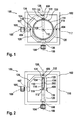
- Figures 1-3 depict a spherical orienting device 100 comprising a mirror 114 as a payload to be oriented in space, relative to a fixed base 102.
- the base 102 is formed as a rectangular frame, which surrounds the mirror 114.
- the rectangular frame of the base 102 lies in the drawing plane.
- the mirror 114 comprises an outer shape substantially conforming to a disk of rotational symmetry around an orientation axis 116, bounded by a cylindrical peripheral surface 128.
- Figure 1 shows the mirror 114 arranged in a neutral position in which it is oriented parallel to the drawing plane, i.e. the plane defined by the base frame 102.
- the side of the mirror 114 facing the observer comprises a circular reflecting mirror plane 115.
- a rim 134 circumscribing the mirror plane 115 is formed on the side of the mirror plane 115 along the periphery of the mirror 114, such that the mirror plane 115 as a whole is recessed with respect to the mirror's 114 cylindrical outer shape.
- the mirror 114 is shown to have been rotated around a spherical centre of rotation 112, into two different exemplary orientations with respect to the base frame 102.
- the mirror 112 is positioned such that the spherical centre of rotation 112 coincides with the centre of its circular mirror plane 115.
- a central shaft 400 is formed that projects away from the centre of the rear surface 200 with cylindrical symmetry around the orientation axis 116 of the mirror 114.
- An L-shaped middle member 122 is provided comprising a radial leg 130, which radially extends from the central shaft 400 along the rear surface 200 outward until slightly beyond the periphery 128 of the mirror 124, and a longitudinal leg 131, which extends perpendicularly from the outer end of the radial leg 130 towards the front side of the mirror 114.
- the radial leg 130 of the middle member 122 comprises a bore in which the central shaft is rotatably held, thus forming a first revolute support joint 118 supporting the mirror 114 rotatably on its orientation axis 116.
- a first rotary actuator 104 and a second rotary actuator 105 are rigidly mounted on adjacent sides of the base frame 102, each in a position close to the centre of the respective frame side.
- the rotary actuators 104, 105 are e.g. configured as electric stepping motors.
- the first actuator 104 comprises a first actuation shaft 106 arranged along a first actuation axis 108, while the second actuator 105 comprises a second actuation shaft 107 arranged along a second actuation axis 109.
- Each actuation shaft 106, 107 is rotatably guided through a respective bore in the base frame 102 from the corresponding actuator 104, 105 into the interior space surrounded by the base frame 102, with both actuation axes 108, 109 intersecting perpendicularly at the spherical centre of rotation 112.
- each of the inner members 120 is fixed to the first actuation shaft 106, extending perpendicularly therefrom into opposing directions.
- Each of the inner members 120 although in the present embodiment formed from piecewise linear portions, follows the general shape of an arc subtending a 90° angle, with an inner radius of the arc that is slightly greater than an outer radius of the cylindrical peripheral surface 128 of the mirror 114. Together, both inner members form a general shape of a combined arc subtending a 120° angle.
- Each inner member 120 comprises at its end a bore which rotatably holds one of two support shafts 404 radially extending from diametrically opposed positions of the cylindrical peripheral surface 128 of the mirror 114.
- Each support shaft 404 together with the corresponding bore forms a first revolute support joint 119, such that the inner members 120 support the mirror 114 rotatably on a support axis 117 defined by a common symmetry axis of the support shafts 404.
- the support axis 117 passes through the spherical centre of rotation 112 and is disposed orthogonal to both the first actuation axis 108 and the orientation axis 116 of the mirror 114.
- an outer member 124 is fixed to the second actuation shaft 107, extending perpendicularly therefrom.
- the outer member 124 although in the present embodiment formed from piecewise linear portions, approximately follows the general shape of an arc subtending a 90° angle, with an inner radius of the arc that is slightly greater than an outer radius of the inner members 120.
- the outer member 124 is formed such that in a position where the inner members 120 and the mirror 114 are rotated into an orientation coplanar with the plane defined by the base frame 102, i.e.
- the outer member 124 does not touch the mirror 114 nor the inner members 120.
- the outer member 124 comprises at its end a bore which rotatably holds a middle shaft 406 that radially extends outward from the longitudinal leg 131 of the middle member 122.
- the middle shaft 406 and corresponding bore form a middle revolute joint 132 configured for rotation around a linkage axis 126 that passes through the spherical centre of rotation 112 and is configured orthogonal to the orientation axis 116 of the mirror 114.
- the mirror 114 is enabled to be rotated into arbitrary spherical orientations over a large angular range by rotary actuation of the actuation shafts 106, 107.
- the first actuation shaft 106 has been rotated by 90° - counter-clockwise as seen from the first actuator 104 -from the position shown in Fig. 1 .
- the second actuation shaft 107 has been rotated further into the same direction over a total of 135°C from its position in Fig. 1 while the first actuation shaft 109 has been rotated by 45° - clockwise as seen from the second actuator 105 - from its position in Fig. 1 .
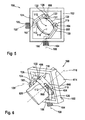
- Figure 4 shows an embodiment in which the central shaft 400 and the radial leg 130 of the middle member 122 are connected by a pair of elastic lamellae 402, thus providing the first support joint 118 as an elastic bearing.
- any of the second support joints 119 and/or the middle revolute joint 132 can be configured as an elastic bearing.
- Figure 5 shows an embodiment comprising only a single inner member 120 and a single second revolute support joint 119.
- the outer member 124 is identical in shape to the inner member 120, which has the advantage of reducing the number of distinct parts to be manufactured.
- the inner 120 and outer 124 sphere members are similar in their mechanical properties such as their respective moment of inertia around the corresponding actuation axis 108, 109 as well as their elastic bending properties etc. This enables the orientation device 100 to respond substantially in a similar to actuation from either one of the actuators 104, 105, leading to particularly smooth and precise operation.
- a spacer ring 500 has been inserted between the inner member 120 and the peripheral surface 128 of the mirror 114, corresponding in length to the radial thickness of the longitudinal leg 131 of the middle member 122, thus enabling identically shaped inner 120 and outer 124 sphere members to be used.
- Figure 6 shows a further embodiment in which the orientable device 614 is of an elongated cylindrical shape, rotationally symmetric around the orientation axis 116.
- the orientable device 614 which for simplification purposes is shown as a plain cylinder, can include a lens system or camera, robotic arm, joystick, spotlight, water cannon or nozzle.
- the middle member, L-shaped in the embodiments of Figs. 1-5 is a cylindrical sheath 620 with an inner diameter that is slightly larger than the outer diameter of the cylindrically-shaped orientable device 614.
- the orientable device 614 Within the sheath 620, the orientable device 614 is held rotatably around the orientation axis 116.
- the sheath 620 and the outer shape of the orientable device 614 itself thus form the first support joint 118 in the present embodiment.
- circumferential slits 690 are formed, each extending over an angle of approximately 90°.
- the support shafts 404 of the second revolute support joints 119 rotatably connect the orientable device 615 to the inner members 120, each through a corresponding one of the slits 690.
- the support shafts 404 slide along the length of the corresponding slit 690.
- spacer rings 500 have been inserted, which are slightly longer than a difference between outer radii of the orientable device 614 and the sheath 620, thus preventing friction and enabling identically shaped inner 120 and outer 124 sphere members to be used, with similar advantages as in the embodiment of Fig. 5 .
- the orienting devices 100 as shown in Figs. 1-6 are manufacturable substantially by using micromechanical manufacturing methods.
- the orienting device of Fig. 1-3 can be seen in Fig. 1 in a neutral position where all major structural parts, i.e. the base 102, the mirror 114, the inner member 120, the middle member 122, and the outer member 124 lie within a flat volume defined by the outer dimensions of the base frame 102.
- these parts are shaped from a common substrate, e.g. a conventional silicon wafer comprising a thickness that corresponds to a height of the base frame 102, perpendicularly to the drawing plane of Figs. 1-3 .
- the mirror surface 115 is formed on the mirror 114 e.g. by metal evaporation.
- the orienting devices 100 of Figs. 4 and 5 can be rotated into a neutral position substantially as shown in Fig. 1 wherein all major structural parts lie within a flat volume defined by the outer dimensions of the respective base frame 102, thus rendering them suitable in principle for being manufactured by micromechanical processes from a common substrate.
Landscapes
- Engineering & Computer Science (AREA)
- General Engineering & Computer Science (AREA)
- Physics & Mathematics (AREA)
- Mechanical Engineering (AREA)
- General Physics & Mathematics (AREA)
- Optics & Photonics (AREA)
- Mechanical Light Control Or Optical Switches (AREA)
Description
- The present invention relates to a spherical orienting device, in particular to a two degree-of-freedom spherical orientation device driven via two actuation shafts, which supports an orientable device having an orientation axis. Under a further aspect, the invention relates to a method for manufacturing such a spherical orienting device.
- Two-dimensional spherical orienting devices, which orient an orientable payload device towards a desired direction in space by rotating it around a fixed point, are used in many fields of technology, for example in inertial sensors such as gyrometers, including in micromechanics, in gyroscopes, in orientable mirrors e.g. in two degree-of-freedom optical scanners, in gyroscopic stabilization of cameras and camera objectives, in water cannons for fire trucks or gaming, in robot wrists, artificial hands and in artillery equipment. Another important field of application is joysticks and similar input devices that sense the spherical orientation of an object rotated by a user, e.g. in user interfaces in automotive or industrial applications, in mobile hydraulic machinery, or in gaming or general computer user interfaces.
- A conventional mechanism for the tilting of an orientable device into two directions is an assembly of two gimbals, i.e. pivoted supports that each allow the rotation of an object about a single axis, wherein one inner gimbal is mounted on an outer gimbal with pivot axes orthogonal or otherwise disposed at a non-collinear angle. However, in order to actuate the inner gimbal, an actuating motor or, in the case of an input device, rotational sensor has to be born by the outer gimbal. This leads to an increase of inertia for the outer gimbal, hindering fast movements, which are required in many applications.
- In another conventional mechanism an orientable device is pressed onto a tip and tilted in two directions. The centre of rotation is located at the apex of the tip where a bearing is installed. Due to such presence of material at the centre of rotation, the object cannot be freely positioned within the mechanism, which is unsuitable for many applications. For example, in a case of the orientable device being a mirror such as in a mirror scanner application, the mechanism does not allow the mirror to be positioned such that the centre of rotation lies in the mirror plane.
-
US 5,966,991 A discloses a two degree-of-freedom spherical orienting device in which a spherical five-bar mechanism with payload support is actuated by two rotary actuators fixed in position to a base. Payload support means for supporting a payload on an orientation axis include first and second revolute support joints each disposed for rotation about a support axis, wherein the orientation axis and each support axis pass through the spherical centre of rotation in mutually orthogonal disposition. An inner sphere arm fixed to the shaft of the first rotary actuator is linked to the first revolute support joint of the payload support, the first actuator axis disposed orthogonal to the first support axis. A middle sphere arm is radially inwardly linked to the second revolute support joint of the payload support and outwardly linked to a middle revolute joint disposed for rotation about a linkage axis passing through the spherical centre of rotation, the linkage axis disposed orthogonal to the second support axis. An outer sphere arm is fixed to the shaft of the second rotary actuator and linked to the middle revolute joint, the linkage axis disposed orthogonal to the second actuator axis. - Although the disclosed orienting device allows the payload to be positioned at the geometric centre of rotation, the device requires a large spherical internal free space around the payload, independent of the shape of the payload to be oriented and of its orientation. Since in general applications orientable payload devices such as listed above are typically not spherically shaped, this leads to an undesirable large space requirement, in particular for orientable payload devices considerably deviating from a spherical shape, e.g. flat or elongate payloads. Large distances of the inner, outer, and middle sphere arms from the orientable device furthermore unfavourably influence high-speed operation due to an increased moment of inertia and the possibility of parasitic movements.
- It is therefore desirable to provide a spherical orienting device that enables to orient non-spherical payload devices, in particular at high speed, without requiring a large installation space.
- Accordingly, a spherical orienting device is provided according to claim 1.
- Because the first support joint is disposed for rotation about the orientation axis of the orientable device, the rotational movement of the middle member with respect to the orientable device describes a generated surface of rotational symmetry around the orientation axis. This enables the middle member to be formed according to an outer contour of the orientable device even when the orientable device substantially deviates from a spherical shape. In particular in typical cases such as mirrors, lenses, cameras, joysticks, cannons or nozzles, where orientable devices typically are flat, disk-like or elongate, tube-like objects that deviate clearly from spherical symmetry but exhibit at least in portions an approximate rotational symmetry around the orientation axis, the middle member is enabled to be shaped to closely conform to the outer contour of the orientable device with minimal gap. Therefore, little installation space is required, while reliable high-speed operation is enabled through a minimised moment of inertia and prevention of parasitic movements.
- According to a preferred development, the orientable device is an optical device, the orientation axis being an optical axis of the optical device. Such devices typically are constructed at least in portions from mirrors, lenses, apertures, tubes etc. arranged with rotational symmetry around the optical axis. Thus, the middle member is enabled to be shaped to conform to the outer shape of the optical device or the rotationally symmetric portion thereof with particularly little gap. Preferably, the orientable device is a mirror, wherein the orientation axis perpendicularly intersects a mirror surface of the mirror. This enables to construct e.g. scanners, projectors and similar ray-reflecting devices that are compact and operable at high speed, even for THz applications, where relatively large mirrors are required due to the longer wavelengths of THz radiation as compared to visible light. Preferably, the orientation axis intersects the mirror surface at the spherical centre of rotation.
- According to a preferred development, the orientable device has a substantially disk-like shape. The middle member comprises a radial leg extending radially along a rear side of the orientable device. This enables the orienting device to be constructed in a particularly compact way, with only minimal material required for the middle member.
- According to a preferred development, at least one of the first support joint, the second support joint and the middle revolute joint comprises an elastic joint. This enables to reduce manufacturing cost because the number of parts and the number of assembly steps are reduced.
- According to a preferred development, the orientable device has an outer shape substantially rotationally symmetric around the orientation axis. The middle member comprises a sheath having an inner shape corresponding to the outer shape of the orientable device. The sheath rotatably holds the orientable device. In this way, a small moment of inertia of the middle member and thus of the moving parts of the orienting device is enabled to be achieved even in the case of elongate orientable devices, since the middle member does not have to e.g. extend longitudinally along the length of the orientable device. Furthermore, also orientable devices such as lenses that require both a rear and a front path along the orientation axis to remain unobstructed during operation are enabled to be oriented.
- Preferably, the sheath comprises at least one slit circumferentially extending around the orientation axis, the second support joint being configured to support the orientable device through the slit. In this way, the sheath is enabled to be positioned anywhere along the length of the orientable device. For example, the sheath can be positioned such that the mass centre of the orientable device is located within the volume surrounded by the sheath, thus enabling smooth control of the rotation at high speed.
- Under a further aspect, a method for manufacturing the spherical orienting device is provided. The method comprises a step of providing a substrate, and a further step, in which at least two of the base, the inner member, the middle member, and the outer member are formed from the substrate. In this way, the orienting device enabled to be manufactured at low cost and small overall size, e.g. as a micromechanical device. A small overall size in turn enables a small moment of inertia and in consequence particularly high operation speed. Preferably, the substrate is a silicon wafer substrate such that conventional, efficient processes of micromechanical manufacturing can be employed.
- According to a preferred development, when the orienting device comprises a mirror, the method further comprises forming the mirror from the substrate. This further simplifies the manufacturing process by reducing the number of parts and the number of assembly steps.
- According to a preferred development, the method further comprises forming at least one of the first support joint, the second support joint and the middle revolute joint as an elastic joint from the substrate. This enables further miniaturisation and cost reduction since less precision is required in manufacturing such elastic joints. Furthermore, the elastic joint can be configured to function as a spring e.g. for returning the orienting device into a neutral position, or as an electric connection to the orientable device.
- Further aspects are illustrated in the accompanying drawing and described in detail in the following part of the description. In the figures,
- Fig. 1
- is a front elevation view of a spherical orienting device according to an em- bodiment of the present invention;
- Fig. 2
- is a front elevation view of the orienting device of
Fig. 1 , in which a first actua- tion shaft has been rotated 90° as compared toFig. 1 ; - Fig. 3
- is a front elevation view of the orienting device of
Fig. 1 , in which the first ac- tuation shaft has been rotated 135° as compared toFig. 1 , and a second ac- tuation shaft has been rotated 45° as compared toFig. 1 ; - Fig. 4
- is a rear perspective view of a spherical orienting device according to another embodiment of the invention;
- Fig. 5
- is a front perspective view of a spherical orienting device according to another embodiment; and
- Fig. 6
- is a perspective view of a spherical orienting device according to a further em- bodiment.
- Unless explicitly stated otherwise, throughout the figures the same reference numbers indicate the same or functionally equivalent means.
-
Figures 1-3 depict aspherical orienting device 100 comprising amirror 114 as a payload to be oriented in space, relative to a fixedbase 102. Thebase 102 is formed as a rectangular frame, which surrounds themirror 114. InFigures 1-3 , the rectangular frame of the base 102 lies in the drawing plane. - The
mirror 114 comprises an outer shape substantially conforming to a disk of rotational symmetry around anorientation axis 116, bounded by a cylindricalperipheral surface 128. -
Figure 1 shows themirror 114 arranged in a neutral position in which it is oriented parallel to the drawing plane, i.e. the plane defined by thebase frame 102. The side of themirror 114 facing the observer comprises a circular reflectingmirror plane 115. Arim 134 circumscribing themirror plane 115 is formed on the side of themirror plane 115 along the periphery of themirror 114, such that themirror plane 115 as a whole is recessed with respect to the mirror's 114 cylindrical outer shape. InFigs. 2 and3 , themirror 114 is shown to have been rotated around a spherical centre ofrotation 112, into two different exemplary orientations with respect to thebase frame 102. Themirror 112 is positioned such that the spherical centre ofrotation 112 coincides with the centre of itscircular mirror plane 115. - On the
rear surface 200 of themirror 114, i.e. the side of themirror 114 opposed to themirror plane 115, acentral shaft 400 is formed that projects away from the centre of therear surface 200 with cylindrical symmetry around theorientation axis 116 of themirror 114. An L-shapedmiddle member 122 is provided comprising aradial leg 130, which radially extends from thecentral shaft 400 along therear surface 200 outward until slightly beyond theperiphery 128 of themirror 124, and alongitudinal leg 131, which extends perpendicularly from the outer end of theradial leg 130 towards the front side of themirror 114. Theradial leg 130 of themiddle member 122 comprises a bore in which the central shaft is rotatably held, thus forming a first revolute support joint 118 supporting themirror 114 rotatably on itsorientation axis 116. - A first
rotary actuator 104 and a secondrotary actuator 105 are rigidly mounted on adjacent sides of thebase frame 102, each in a position close to the centre of the respective frame side. Therotary actuators first actuator 104 comprises afirst actuation shaft 106 arranged along afirst actuation axis 108, while thesecond actuator 105 comprises asecond actuation shaft 107 arranged along asecond actuation axis 109. Eachactuation shaft base frame 102 from the correspondingactuator base frame 102, with bothactuation axes rotation 112. - On the interior-facing side of the bore guiding the
first actuation shaft 106, twoinner members 120 are fixed to thefirst actuation shaft 106, extending perpendicularly therefrom into opposing directions. Each of theinner members 120, although in the present embodiment formed from piecewise linear portions, follows the general shape of an arc subtending a 90° angle, with an inner radius of the arc that is slightly greater than an outer radius of the cylindricalperipheral surface 128 of themirror 114. Together, both inner members form a general shape of a combined arc subtending a 120° angle. - Each
inner member 120 comprises at its end a bore which rotatably holds one of twosupport shafts 404 radially extending from diametrically opposed positions of the cylindricalperipheral surface 128 of themirror 114. Eachsupport shaft 404 together with the corresponding bore forms a first revolute support joint 119, such that theinner members 120 support themirror 114 rotatably on asupport axis 117 defined by a common symmetry axis of thesupport shafts 404. Thesupport axis 117 passes through the spherical centre ofrotation 112 and is disposed orthogonal to both thefirst actuation axis 108 and theorientation axis 116 of themirror 114. - On the interior-facing side of the bore guiding the
second actuation shaft 107 through thebase frame 102, anouter member 124 is fixed to thesecond actuation shaft 107, extending perpendicularly therefrom. Theouter member 124, although in the present embodiment formed from piecewise linear portions, approximately follows the general shape of an arc subtending a 90° angle, with an inner radius of the arc that is slightly greater than an outer radius of theinner members 120. As can be seen inFig. 1 , theouter member 124 is formed such that in a position where theinner members 120 and themirror 114 are rotated into an orientation coplanar with the plane defined by thebase frame 102, i.e. by the actuation axes 108, 109, and theouter member 124 is rotated into a position coplanar with the plane defined by thebase frame 102 and facing away from the side of thefirst actuator 104, theouter member 124 does not touch themirror 114 nor theinner members 120. - The
outer member 124 comprises at its end a bore which rotatably holds amiddle shaft 406 that radially extends outward from thelongitudinal leg 131 of themiddle member 122. Together, themiddle shaft 406 and corresponding bore form a middle revolute joint 132 configured for rotation around alinkage axis 126 that passes through the spherical centre ofrotation 112 and is configured orthogonal to theorientation axis 116 of themirror 114. - As demonstrated in
Figs. 2 and3 , themirror 114 is enabled to be rotated into arbitrary spherical orientations over a large angular range by rotary actuation of theactuation shafts Fig. 2 , thefirst actuation shaft 106 has been rotated by 90° - counter-clockwise as seen from the first actuator 104 -from the position shown inFig. 1 . InFig. 3 , thesecond actuation shaft 107 has been rotated further into the same direction over a total of 135°C from its position inFig. 1 while thefirst actuation shaft 109 has been rotated by 45° - clockwise as seen from the second actuator 105 - from its position inFig. 1 . -
Figure 4 shows an embodiment in which thecentral shaft 400 and theradial leg 130 of themiddle member 122 are connected by a pair ofelastic lamellae 402, thus providing the first support joint 118 as an elastic bearing. In alternative embodiments, additionally or alternatively any of the second support joints 119 and/or the middle revolute joint 132 can be configured as an elastic bearing. -
Figure 5 shows an embodiment comprising only a singleinner member 120 and a single second revolute support joint 119. In this embodiment, theouter member 124 is identical in shape to theinner member 120, which has the advantage of reducing the number of distinct parts to be manufactured. Furthermore, due to the similarity in shape the inner 120 and outer 124 sphere members are similar in their mechanical properties such as their respective moment of inertia around the correspondingactuation axis orientation device 100 to respond substantially in a similar to actuation from either one of theactuators spacer ring 500 has been inserted between theinner member 120 and theperipheral surface 128 of themirror 114, corresponding in length to the radial thickness of thelongitudinal leg 131 of themiddle member 122, thus enabling identically shaped inner 120 and outer 124 sphere members to be used. -
Figure 6 shows a further embodiment in which theorientable device 614 is of an elongated cylindrical shape, rotationally symmetric around theorientation axis 116. Examples of theorientable device 614, which for simplification purposes is shown as a plain cylinder, can include a lens system or camera, robotic arm, joystick, spotlight, water cannon or nozzle. Here, the middle member, L-shaped in the embodiments ofFigs. 1-5 , is acylindrical sheath 620 with an inner diameter that is slightly larger than the outer diameter of the cylindrically-shapedorientable device 614. Within thesheath 620, theorientable device 614 is held rotatably around theorientation axis 116. Thesheath 620 and the outer shape of theorientable device 614 itself thus form the first support joint 118 in the present embodiment. - In two diametrically opposed sections of the
sheath 620circumferential slits 690 are formed, each extending over an angle of approximately 90°. Thesupport shafts 404 of the secondrevolute support joints 119 rotatably connect the orientable device 615 to theinner members 120, each through a corresponding one of theslits 690. When theorientable device 614 is rotated around itsorientation axis 116, thesupport shafts 404 slide along the length of thecorresponding slit 690. Between theinner member 106 and theorientable device 614, spacer rings 500 have been inserted, which are slightly longer than a difference between outer radii of theorientable device 614 and thesheath 620, thus preventing friction and enabling identically shaped inner 120 and outer 124 sphere members to be used, with similar advantages as in the embodiment ofFig. 5 . - The orienting
devices 100 as shown inFigs. 1-6 are manufacturable substantially by using micromechanical manufacturing methods. For example, the orienting device ofFig. 1-3 can be seen inFig. 1 in a neutral position where all major structural parts, i.e. thebase 102, themirror 114, theinner member 120, themiddle member 122, and theouter member 124 lie within a flat volume defined by the outer dimensions of thebase frame 102. In an exemplary micromechanical manufacturing process, these parts are shaped from a common substrate, e.g. a conventional silicon wafer comprising a thickness that corresponds to a height of thebase frame 102, perpendicularly to the drawing plane ofFigs. 1-3 . In a further step, themirror surface 115 is formed on themirror 114 e.g. by metal evaporation. - Moreover, also the orienting
devices 100 ofFigs. 4 and5 , as well as the orientingdevice 100 ofFig. 6 when excluding theorientable device 620, can be rotated into a neutral position substantially as shown inFig. 1 wherein all major structural parts lie within a flat volume defined by the outer dimensions of therespective base frame 102, thus rendering them suitable in principle for being manufactured by micromechanical processes from a common substrate. Furthermore suited to such processes is the forming of one or more of therevolute joints first support joint 118 of the orienting device ofFig. 4 .
Claims (10)
- A spherical orienting device (100) comprising:- a base (102);- first (106) and second (107) actuation shafts, rotatably held by the base (102) for rotary actuation about first (108) and second (109) actuation axes intersecting orthogonally at a spherical centre of rotation (112);- an orientable device (114; 614) supported by first (118) and second (119) revolute support joints, wherein the first support joint (118) is disposed for rotation about an orientation axis (116) of the orientable device (114; 614) and the second support joint (119) is disposed for rotation about a support axis (117) orthogonally intersecting the orientation axis (116) at the spherical centre of rotation (112);- an inner member (120) fixed to the first actuation shaft (106) and rotatably connected by the second support joint (119) to the orientable device (114; 614), the firs actuation axis (108) disposed orthogonal to the support axis (117); characterised in that,- a middle member (122; 620) is inwardly rotatably connected by the first support joint (118) to the orientable device (114; 614) and outwardly linked to a middle revolute joint (132) disposed for rotation about a linkage axis (126) passing through the spherical centre of rotation (112), the linkage axis (126) disposed orthogonal to the orientation axis (116); and- an outer member (124) is fixed to the second actuation shaft (107) and rotatably connected by the middle revolute joint (132) to the middle member (122; 620), the linkage axis (126) disposed orthogonal to the second actuation axis (109).
- The spherical orienting device of claim 1, wherein the orientable device (114; 614) is an optical device, the orientation axis (116) being an optical axis of the optical device.
- The spherical orienting device of claim 2, wherein the orientable device (114; 614) is a mirror (114), the orientation axis (116) intersecting a mirror surface (115) of the mirror (114) perpendicularly, in particular at the spherical centre of rotation (112).
- The spherical orienting device of any one of the preceding claims, wherein the orientable device (114) has a substantially disk-like shape, and wherein the middle member (122) comprises a radial leg (130) extending radially along a rear side (129) of the orientable device (114).
- The spherical orienting device of any of the preceding claims, wherein at least one of the first support joint (118), the second support joint (119) and the middle revolute joint (132) comprises an elastic joint (402).
- The spherical orienting device of any of the preceding claims, wherein the orientable device (614) has an outer shape substantially rotationally symmetric around the orientation axis (116), the middle member (620) comprising a sheath (620) having an inner shape corresponding to the outer shape of the orientable device (614).
- The spherical orienting device of claim 6, wherein the sheath (620) comprises at least one slit (690) circumferentially extending around the orientation axis (116), the second support joint (119) supporting the orientable device through the slit (690).
- A method for manufacturing the spherical orienting device (100) of any one of the preceding claims, comprising:- providing a substrate, in particular a silicon wafer substrate; and- forming at least two of the base (102), the inner member (120), the middle member (122), and the outer member (124) from the substrate.
- The method of claim 8, when referring to claim 3, further comprising forming the mirror (112) from the substrate.
- The method of claim 8 or 9, comprising forming at least one of the first support joint (118), the second support joint (119) and the middle revolute joint (132) as an elastic joint (402) from the substrate.
Priority Applications (3)
| Application Number | Priority Date | Filing Date | Title |
|---|---|---|---|
| EP09100290A EP2256397B1 (en) | 2009-05-26 | 2009-05-26 | Spherical Orienting Device and Method for manufacturing the same |
| US12/800,439 US8876077B2 (en) | 2009-05-26 | 2010-05-14 | Spherical orienting device and method for manufacturing the same |
| CN201010229217.1A CN101943312B (en) | 2009-05-26 | 2010-05-25 | Spherical orienting device and method for manufacturing the same |
Applications Claiming Priority (1)
| Application Number | Priority Date | Filing Date | Title |
|---|---|---|---|
| EP09100290A EP2256397B1 (en) | 2009-05-26 | 2009-05-26 | Spherical Orienting Device and Method for manufacturing the same |
Publications (2)
| Publication Number | Publication Date |
|---|---|
| EP2256397A1 EP2256397A1 (en) | 2010-12-01 |
| EP2256397B1 true EP2256397B1 (en) | 2012-07-11 |
Family
ID=41037901
Family Applications (1)
| Application Number | Title | Priority Date | Filing Date |
|---|---|---|---|
| EP09100290A Not-in-force EP2256397B1 (en) | 2009-05-26 | 2009-05-26 | Spherical Orienting Device and Method for manufacturing the same |
Country Status (3)
| Country | Link |
|---|---|
| US (1) | US8876077B2 (en) |
| EP (1) | EP2256397B1 (en) |
| CN (1) | CN101943312B (en) |
Families Citing this family (26)
| Publication number | Priority date | Publication date | Assignee | Title |
|---|---|---|---|---|
| EP2256397B1 (en) * | 2009-05-26 | 2012-07-11 | Robert Bosch GmbH | Spherical Orienting Device and Method for manufacturing the same |
| JP5798823B2 (en) * | 2011-07-22 | 2015-10-21 | 株式会社ミツトヨ | Abscissa calibration jig and abscissa calibration method for laser interference measuring apparatus |
| PL2579234T3 (en) * | 2011-10-07 | 2019-03-29 | E2M Technologies B.V. | Motion platform system |
| CN102681129B (en) * | 2012-05-04 | 2014-11-12 | 华中科技大学 | Optical panel bracket with multi-degree-of-freedom adjustment capacity |
| NL2009160C2 (en) * | 2012-07-09 | 2014-01-13 | Mci Mirror Controls Int Nl Bv | ADJUSTMENT INSTRUMENT. |
| CN102873501B (en) * | 2012-09-29 | 2014-10-29 | 中国科学院西安光学精密机械研究所 | High-precision combined adjusting and correcting method for pendulum mirror shafting assembly |
| SE538145C2 (en) * | 2013-08-28 | 2016-03-15 | Löfs Specialmaskiner Ab | Lifting device for use at a manual work station |
| CN103470925B (en) * | 2013-09-04 | 2015-07-08 | 中国科学院深圳先进技术研究院 | Automatic-control spatial rotating device |
| US9579786B2 (en) * | 2013-09-26 | 2017-02-28 | Wen-Der TRUI | Spherical coordinates manipulating mechanism |
| TWI574722B (en) * | 2014-05-15 | 2017-03-21 | 崔文德 | Spherical coordinates orientating mechanism |
| CN103629495B (en) * | 2013-12-16 | 2016-01-06 | 中国科学院苏州生物医学工程技术研究所 | A kind of device of fixing spheroidal object |
| WO2015181771A1 (en) | 2014-05-30 | 2015-12-03 | Fondazione Istituto Italiano Di Tecnologia | Device for the spherical orientation of an optical element, in particular for directing a light beam, such as a laser beam |
| JP6228680B1 (en) * | 2015-08-14 | 2017-11-08 | エスゼット ディージェイアイ オスモ テクノロジー カンパニー リミテッドSZ DJI Osmo Technology Co., Ltd. | Gimbal mechanism |
| US11769686B2 (en) * | 2016-09-29 | 2023-09-26 | Intel Corporation | Methods and apparatus for electroless plating dispense |
| CN107748567B (en) * | 2017-10-31 | 2021-05-28 | 兰州空间技术物理研究所 | An Attitude Adjustment Mechanism for Ground Simulation Test of Space Detection Sensor |
| EP3737988B1 (en) * | 2018-01-12 | 2021-11-24 | Barco n.v. | Device for elastic pivoting about two orthogonal axes |
| WO2020144528A1 (en) * | 2019-01-07 | 2020-07-16 | Corephotonics Ltd. | Rotation mechanism with sliding joint |
| CN113217788B (en) * | 2020-01-21 | 2022-03-01 | 杭州海康威视数字技术股份有限公司 | Flush Mount Bracket and Camera Assembly Including The Same |
| US11812126B2 (en) * | 2020-01-27 | 2023-11-07 | Sanctuary Cognitive Systems Corporation | Eye cartridge |
| CN111603008B (en) * | 2020-05-29 | 2021-09-14 | 温州大学 | Cosmetic mirror |
| CN112393080B (en) * | 2020-12-01 | 2022-07-05 | 国电长源第一发电有限责任公司 | Information display device for intelligent pre-control system and use method thereof |
| US11399639B1 (en) * | 2021-02-05 | 2022-08-02 | Harbor Freight Tools Usa, Inc. | Self-righting packaging for display of item with aperture |
| CN113090881B (en) * | 2021-03-25 | 2022-12-23 | 浙江数银信息技术有限公司 | Monitoring device for power grid equipment management of electric power machine room |
| IL285055B (en) * | 2021-07-21 | 2022-08-01 | Rafael Advanced Defense Systems Ltd | Spherical orientation mechanism driven by a biaxial motor |
| CN114576512B (en) * | 2022-01-25 | 2023-08-01 | 深圳联合创达科技有限公司 | Movable pitch diameter cradle head |
| CN119270461B (en) * | 2024-12-11 | 2025-12-16 | 苏州镭陌科技有限公司 | A mirror adjustment device |
Family Cites Families (13)
| Publication number | Priority date | Publication date | Assignee | Title |
|---|---|---|---|---|
| US3731544A (en) * | 1971-03-31 | 1973-05-08 | Singer Co | Star tracker system |
| US4233634A (en) * | 1979-06-22 | 1980-11-11 | Adams Jay W | Video camera with adjustable mount and counterbalance |
| US4678289A (en) * | 1984-09-25 | 1987-07-07 | Siemens Aktiengesellschaft | Apparatus for the deflection of a light beam |
| US4878393A (en) * | 1988-05-27 | 1989-11-07 | Oprea Duta | Dextrous spherical robot wrist |
| US5243873A (en) * | 1992-01-23 | 1993-09-14 | Honeywell Inc. | Two-axis motion mechanism |
| US5418567A (en) * | 1993-01-29 | 1995-05-23 | Bayport Controls, Inc. | Surveillance camera system |
| US5966991A (en) | 1997-04-23 | 1999-10-19 | Universite Laval | Two degree-of-freedom spherical orienting device |
| US6484602B1 (en) * | 1999-06-21 | 2002-11-26 | National Institute Of Standards And Technology | Six-degree of freedom micro-positioner |
| US7468826B2 (en) * | 2002-05-03 | 2008-12-23 | Texas Instruments Incorporated | Silicon mirrors having reduced hinge stress from temperature variations |
| FR2850599B1 (en) * | 2003-02-05 | 2006-03-03 | Centre Nat Rech Scient | DEVICE FOR MOVING AND ORIENTING AN OBJECT IN THE SPACE AND USE IN RAPID MACHINING |
| EP1746333A1 (en) * | 2005-07-20 | 2007-01-24 | Piumaworld S.r.l. | A unit for moving television cameras or film cameras |
| US8167872B2 (en) * | 2006-01-25 | 2012-05-01 | Intuitive Surgical Operations, Inc. | Center robotic arm with five-bar spherical linkage for endoscopic camera |
| EP2256397B1 (en) * | 2009-05-26 | 2012-07-11 | Robert Bosch GmbH | Spherical Orienting Device and Method for manufacturing the same |
-
2009
- 2009-05-26 EP EP09100290A patent/EP2256397B1/en not_active Not-in-force
-
2010
- 2010-05-14 US US12/800,439 patent/US8876077B2/en not_active Expired - Fee Related
- 2010-05-25 CN CN201010229217.1A patent/CN101943312B/en not_active Expired - Fee Related
Also Published As
| Publication number | Publication date |
|---|---|
| US8876077B2 (en) | 2014-11-04 |
| CN101943312A (en) | 2011-01-12 |
| US20100320356A1 (en) | 2010-12-23 |
| EP2256397A1 (en) | 2010-12-01 |
| CN101943312B (en) | 2015-04-22 |
Similar Documents
| Publication | Publication Date | Title |
|---|---|---|
| EP2256397B1 (en) | Spherical Orienting Device and Method for manufacturing the same | |
| US5966991A (en) | Two degree-of-freedom spherical orienting device | |
| CN103261711B (en) | Small flexible universal joint and spacecraft incorporating same | |
| JP2009205181A (en) | Device for fixing and adjusting element to be supported | |
| US8730597B2 (en) | Holding apparatus and optical apparatus | |
| CA2235759C (en) | Two degree-of-freedom spherical orienting device | |
| JP2016130127A (en) | Assembly for aiming instrument | |
| CN106569328B (en) | Five-bar mechanism, swing mirror system and two-dimensional swing mirror device | |
| US4304381A (en) | Aimable mounting apparatus | |
| US20120275038A1 (en) | Optical Pointing Mechanism | |
| JP2987211B2 (en) | Articulated reflector device | |
| EP1340957A2 (en) | Method and device for prevention of gimbal-locking | |
| JP3748062B2 (en) | Guiding device and guiding method | |
| US20210234451A1 (en) | Multi-degree-of-freedom electromagnetic machine with payload attachment assembly | |
| CN108445598B (en) | Lens module and optical device | |
| US20240402478A1 (en) | Telescope and spacecraft system | |
| US12305794B2 (en) | Two-axis motor-driven spherical orienting mechanism | |
| JP6977954B2 (en) | 2-axis solid cam mechanism | |
| CN205374871U (en) | Five-rod mechanism, swing mirror system and two-dimensional swing mirror device | |
| EP3935426B1 (en) | Magnetic joint and optical mount using the same | |
| US10685771B1 (en) | Magnetic joint and optical mount using the same | |
| KR20250149901A (en) | System and method for fine pointing of a payload | |
| JP2000187150A (en) | Movable mirror controller | |
| JP2002098784A (en) | Rotary type multi-degree-of-freedom mechanism | |
| GB2263342A (en) | Gyro-stabilised optical system |
Legal Events
| Date | Code | Title | Description |
|---|---|---|---|
| PUAI | Public reference made under article 153(3) epc to a published international application that has entered the european phase |
Free format text: ORIGINAL CODE: 0009012 |
|
| AK | Designated contracting states |
Kind code of ref document: A1 Designated state(s): AT BE BG CH CY CZ DE DK EE ES FI FR GB GR HR HU IE IS IT LI LT LU LV MC MK MT NL NO PL PT RO SE SI SK TR |
|
| AX | Request for extension of the european patent |
Extension state: AL BA RS |
|
| 17P | Request for examination filed |
Effective date: 20110601 |
|
| 17Q | First examination report despatched |
Effective date: 20110704 |
|
| GRAP | Despatch of communication of intention to grant a patent |
Free format text: ORIGINAL CODE: EPIDOSNIGR1 |
|
| RIC1 | Information provided on ipc code assigned before grant |
Ipc: G02B 26/08 20060101ALI20120203BHEP Ipc: F16M 11/12 20060101AFI20120203BHEP |
|
| GRAS | Grant fee paid |
Free format text: ORIGINAL CODE: EPIDOSNIGR3 |
|
| GRAA | (expected) grant |
Free format text: ORIGINAL CODE: 0009210 |
|
| AK | Designated contracting states |
Kind code of ref document: B1 Designated state(s): AT BE BG CH CY CZ DE DK EE ES FI FR GB GR HR HU IE IS IT LI LT LU LV MC MK MT NL NO PL PT RO SE SI SK TR |
|
| REG | Reference to a national code |
Ref country code: GB Ref legal event code: FG4D |
|
| REG | Reference to a national code |
Ref country code: CH Ref legal event code: EP |
|
| REG | Reference to a national code |
Ref country code: AT Ref legal event code: REF Ref document number: 566331 Country of ref document: AT Kind code of ref document: T Effective date: 20120715 |
|
| REG | Reference to a national code |
Ref country code: IE Ref legal event code: FG4D |
|
| REG | Reference to a national code |
Ref country code: DE Ref legal event code: R096 Ref document number: 602009008138 Country of ref document: DE Effective date: 20120906 |
|
| REG | Reference to a national code |
Ref country code: NL Ref legal event code: VDEP Effective date: 20120711 |
|
| REG | Reference to a national code |
Ref country code: AT Ref legal event code: MK05 Ref document number: 566331 Country of ref document: AT Kind code of ref document: T Effective date: 20120711 |
|
| REG | Reference to a national code |
Ref country code: LT Ref legal event code: MG4D Effective date: 20120711 |
|
| PG25 | Lapsed in a contracting state [announced via postgrant information from national office to epo] |
Ref country code: HR Free format text: LAPSE BECAUSE OF FAILURE TO SUBMIT A TRANSLATION OF THE DESCRIPTION OR TO PAY THE FEE WITHIN THE PRESCRIBED TIME-LIMIT Effective date: 20120711 Ref country code: NO Free format text: LAPSE BECAUSE OF FAILURE TO SUBMIT A TRANSLATION OF THE DESCRIPTION OR TO PAY THE FEE WITHIN THE PRESCRIBED TIME-LIMIT Effective date: 20121011 Ref country code: CY Free format text: LAPSE BECAUSE OF FAILURE TO SUBMIT A TRANSLATION OF THE DESCRIPTION OR TO PAY THE FEE WITHIN THE PRESCRIBED TIME-LIMIT Effective date: 20120711 Ref country code: LT Free format text: LAPSE BECAUSE OF FAILURE TO SUBMIT A TRANSLATION OF THE DESCRIPTION OR TO PAY THE FEE WITHIN THE PRESCRIBED TIME-LIMIT Effective date: 20120711 Ref country code: IS Free format text: LAPSE BECAUSE OF FAILURE TO SUBMIT A TRANSLATION OF THE DESCRIPTION OR TO PAY THE FEE WITHIN THE PRESCRIBED TIME-LIMIT Effective date: 20121111 Ref country code: AT Free format text: LAPSE BECAUSE OF FAILURE TO SUBMIT A TRANSLATION OF THE DESCRIPTION OR TO PAY THE FEE WITHIN THE PRESCRIBED TIME-LIMIT Effective date: 20120711 Ref country code: BE Free format text: LAPSE BECAUSE OF FAILURE TO SUBMIT A TRANSLATION OF THE DESCRIPTION OR TO PAY THE FEE WITHIN THE PRESCRIBED TIME-LIMIT Effective date: 20120711 Ref country code: FI Free format text: LAPSE BECAUSE OF FAILURE TO SUBMIT A TRANSLATION OF THE DESCRIPTION OR TO PAY THE FEE WITHIN THE PRESCRIBED TIME-LIMIT Effective date: 20120711 |
|
| PG25 | Lapsed in a contracting state [announced via postgrant information from national office to epo] |
Ref country code: SE Free format text: LAPSE BECAUSE OF FAILURE TO SUBMIT A TRANSLATION OF THE DESCRIPTION OR TO PAY THE FEE WITHIN THE PRESCRIBED TIME-LIMIT Effective date: 20120711 Ref country code: SI Free format text: LAPSE BECAUSE OF FAILURE TO SUBMIT A TRANSLATION OF THE DESCRIPTION OR TO PAY THE FEE WITHIN THE PRESCRIBED TIME-LIMIT Effective date: 20120711 Ref country code: LV Free format text: LAPSE BECAUSE OF FAILURE TO SUBMIT A TRANSLATION OF THE DESCRIPTION OR TO PAY THE FEE WITHIN THE PRESCRIBED TIME-LIMIT Effective date: 20120711 Ref country code: PL Free format text: LAPSE BECAUSE OF FAILURE TO SUBMIT A TRANSLATION OF THE DESCRIPTION OR TO PAY THE FEE WITHIN THE PRESCRIBED TIME-LIMIT Effective date: 20120711 Ref country code: GR Free format text: LAPSE BECAUSE OF FAILURE TO SUBMIT A TRANSLATION OF THE DESCRIPTION OR TO PAY THE FEE WITHIN THE PRESCRIBED TIME-LIMIT Effective date: 20121012 Ref country code: PT Free format text: LAPSE BECAUSE OF FAILURE TO SUBMIT A TRANSLATION OF THE DESCRIPTION OR TO PAY THE FEE WITHIN THE PRESCRIBED TIME-LIMIT Effective date: 20121112 |
|
| PG25 | Lapsed in a contracting state [announced via postgrant information from national office to epo] |
Ref country code: NL Free format text: LAPSE BECAUSE OF FAILURE TO SUBMIT A TRANSLATION OF THE DESCRIPTION OR TO PAY THE FEE WITHIN THE PRESCRIBED TIME-LIMIT Effective date: 20120711 |
|
| PG25 | Lapsed in a contracting state [announced via postgrant information from national office to epo] |
Ref country code: DK Free format text: LAPSE BECAUSE OF FAILURE TO SUBMIT A TRANSLATION OF THE DESCRIPTION OR TO PAY THE FEE WITHIN THE PRESCRIBED TIME-LIMIT Effective date: 20120711 Ref country code: RO Free format text: LAPSE BECAUSE OF FAILURE TO SUBMIT A TRANSLATION OF THE DESCRIPTION OR TO PAY THE FEE WITHIN THE PRESCRIBED TIME-LIMIT Effective date: 20120711 Ref country code: EE Free format text: LAPSE BECAUSE OF FAILURE TO SUBMIT A TRANSLATION OF THE DESCRIPTION OR TO PAY THE FEE WITHIN THE PRESCRIBED TIME-LIMIT Effective date: 20120711 Ref country code: ES Free format text: LAPSE BECAUSE OF FAILURE TO SUBMIT A TRANSLATION OF THE DESCRIPTION OR TO PAY THE FEE WITHIN THE PRESCRIBED TIME-LIMIT Effective date: 20121022 Ref country code: CZ Free format text: LAPSE BECAUSE OF FAILURE TO SUBMIT A TRANSLATION OF THE DESCRIPTION OR TO PAY THE FEE WITHIN THE PRESCRIBED TIME-LIMIT Effective date: 20120711 |
|
| PLBE | No opposition filed within time limit |
Free format text: ORIGINAL CODE: 0009261 |
|
| STAA | Information on the status of an ep patent application or granted ep patent |
Free format text: STATUS: NO OPPOSITION FILED WITHIN TIME LIMIT |
|
| PG25 | Lapsed in a contracting state [announced via postgrant information from national office to epo] |
Ref country code: IT Free format text: LAPSE BECAUSE OF FAILURE TO SUBMIT A TRANSLATION OF THE DESCRIPTION OR TO PAY THE FEE WITHIN THE PRESCRIBED TIME-LIMIT Effective date: 20120711 Ref country code: SK Free format text: LAPSE BECAUSE OF FAILURE TO SUBMIT A TRANSLATION OF THE DESCRIPTION OR TO PAY THE FEE WITHIN THE PRESCRIBED TIME-LIMIT Effective date: 20120711 |
|
| 26N | No opposition filed |
Effective date: 20130412 |
|
| PG25 | Lapsed in a contracting state [announced via postgrant information from national office to epo] |
Ref country code: BG Free format text: LAPSE BECAUSE OF FAILURE TO SUBMIT A TRANSLATION OF THE DESCRIPTION OR TO PAY THE FEE WITHIN THE PRESCRIBED TIME-LIMIT Effective date: 20121011 |
|
| REG | Reference to a national code |
Ref country code: DE Ref legal event code: R097 Ref document number: 602009008138 Country of ref document: DE Effective date: 20130412 |
|
| PG25 | Lapsed in a contracting state [announced via postgrant information from national office to epo] |
Ref country code: MC Free format text: LAPSE BECAUSE OF FAILURE TO SUBMIT A TRANSLATION OF THE DESCRIPTION OR TO PAY THE FEE WITHIN THE PRESCRIBED TIME-LIMIT Effective date: 20120711 |
|
| REG | Reference to a national code |
Ref country code: CH Ref legal event code: PL |
|
| PG25 | Lapsed in a contracting state [announced via postgrant information from national office to epo] |
Ref country code: LI Free format text: LAPSE BECAUSE OF NON-PAYMENT OF DUE FEES Effective date: 20130531 Ref country code: CH Free format text: LAPSE BECAUSE OF NON-PAYMENT OF DUE FEES Effective date: 20130531 |
|
| REG | Reference to a national code |
Ref country code: IE Ref legal event code: MM4A |
|
| PG25 | Lapsed in a contracting state [announced via postgrant information from national office to epo] |
Ref country code: IE Free format text: LAPSE BECAUSE OF NON-PAYMENT OF DUE FEES Effective date: 20130526 |
|
| PG25 | Lapsed in a contracting state [announced via postgrant information from national office to epo] |
Ref country code: MT Free format text: LAPSE BECAUSE OF FAILURE TO SUBMIT A TRANSLATION OF THE DESCRIPTION OR TO PAY THE FEE WITHIN THE PRESCRIBED TIME-LIMIT Effective date: 20120711 |
|
| PG25 | Lapsed in a contracting state [announced via postgrant information from national office to epo] |
Ref country code: TR Free format text: LAPSE BECAUSE OF FAILURE TO SUBMIT A TRANSLATION OF THE DESCRIPTION OR TO PAY THE FEE WITHIN THE PRESCRIBED TIME-LIMIT Effective date: 20120711 |
|
| PG25 | Lapsed in a contracting state [announced via postgrant information from national office to epo] |
Ref country code: MK Free format text: LAPSE BECAUSE OF FAILURE TO SUBMIT A TRANSLATION OF THE DESCRIPTION OR TO PAY THE FEE WITHIN THE PRESCRIBED TIME-LIMIT Effective date: 20120711 Ref country code: LU Free format text: LAPSE BECAUSE OF NON-PAYMENT OF DUE FEES Effective date: 20130526 Ref country code: HU Free format text: LAPSE BECAUSE OF FAILURE TO SUBMIT A TRANSLATION OF THE DESCRIPTION OR TO PAY THE FEE WITHIN THE PRESCRIBED TIME-LIMIT; INVALID AB INITIO Effective date: 20090526 |
|
| REG | Reference to a national code |
Ref country code: FR Ref legal event code: PLFP Year of fee payment: 8 |
|
| PGFP | Annual fee paid to national office [announced via postgrant information from national office to epo] |
Ref country code: GB Payment date: 20160523 Year of fee payment: 8 |
|
| PGFP | Annual fee paid to national office [announced via postgrant information from national office to epo] |
Ref country code: FR Payment date: 20160523 Year of fee payment: 8 |
|
| PGFP | Annual fee paid to national office [announced via postgrant information from national office to epo] |
Ref country code: DE Payment date: 20160726 Year of fee payment: 8 |
|
| REG | Reference to a national code |
Ref country code: DE Ref legal event code: R119 Ref document number: 602009008138 Country of ref document: DE |
|
| GBPC | Gb: european patent ceased through non-payment of renewal fee |
Effective date: 20170526 |
|
| REG | Reference to a national code |
Ref country code: FR Ref legal event code: ST Effective date: 20180131 |
|
| PG25 | Lapsed in a contracting state [announced via postgrant information from national office to epo] |
Ref country code: GB Free format text: LAPSE BECAUSE OF NON-PAYMENT OF DUE FEES Effective date: 20170526 Ref country code: DE Free format text: LAPSE BECAUSE OF NON-PAYMENT OF DUE FEES Effective date: 20171201 |
|
| PG25 | Lapsed in a contracting state [announced via postgrant information from national office to epo] |
Ref country code: FR Free format text: LAPSE BECAUSE OF NON-PAYMENT OF DUE FEES Effective date: 20170531 |