EP2256012A1 - Method and control device for checking an electrically controlled handbrake for a vehicle - Google Patents
Method and control device for checking an electrically controlled handbrake for a vehicle Download PDFInfo
- Publication number
- EP2256012A1 EP2256012A1 EP10163279A EP10163279A EP2256012A1 EP 2256012 A1 EP2256012 A1 EP 2256012A1 EP 10163279 A EP10163279 A EP 10163279A EP 10163279 A EP10163279 A EP 10163279A EP 2256012 A1 EP2256012 A1 EP 2256012A1
- Authority
- EP
- European Patent Office
- Prior art keywords
- parking brake
- test routine
- brake system
- vehicle
- test
- Prior art date
- Legal status (The legal status is an assumption and is not a legal conclusion. Google has not performed a legal analysis and makes no representation as to the accuracy of the status listed.)
- Granted
Links
Images


Classifications
-
- B—PERFORMING OPERATIONS; TRANSPORTING
- B60—VEHICLES IN GENERAL
- B60T—VEHICLE BRAKE CONTROL SYSTEMS OR PARTS THEREOF; BRAKE CONTROL SYSTEMS OR PARTS THEREOF, IN GENERAL; ARRANGEMENT OF BRAKING ELEMENTS ON VEHICLES IN GENERAL; PORTABLE DEVICES FOR PREVENTING UNWANTED MOVEMENT OF VEHICLES; VEHICLE MODIFICATIONS TO FACILITATE COOLING OF BRAKES
- B60T17/00—Component parts, details, or accessories of power brake systems not covered by groups B60T8/00, B60T13/00 or B60T15/00, or presenting other characteristic features
- B60T17/18—Safety devices; Monitoring
- B60T17/22—Devices for monitoring or checking brake systems; Signal devices
- B60T17/221—Procedure or apparatus for checking or keeping in a correct functioning condition of brake systems
-
- B—PERFORMING OPERATIONS; TRANSPORTING
- B60—VEHICLES IN GENERAL
- B60T—VEHICLE BRAKE CONTROL SYSTEMS OR PARTS THEREOF; BRAKE CONTROL SYSTEMS OR PARTS THEREOF, IN GENERAL; ARRANGEMENT OF BRAKING ELEMENTS ON VEHICLES IN GENERAL; PORTABLE DEVICES FOR PREVENTING UNWANTED MOVEMENT OF VEHICLES; VEHICLE MODIFICATIONS TO FACILITATE COOLING OF BRAKES
- B60T13/00—Transmitting braking action from initiating means to ultimate brake actuator with power assistance or drive; Brake systems incorporating such transmitting means, e.g. air-pressure brake systems
- B60T13/10—Transmitting braking action from initiating means to ultimate brake actuator with power assistance or drive; Brake systems incorporating such transmitting means, e.g. air-pressure brake systems with fluid assistance, drive, or release
- B60T13/66—Electrical control in fluid-pressure brake systems
- B60T13/662—Electrical control in fluid-pressure brake systems characterised by specified functions of the control system components
-
- B—PERFORMING OPERATIONS; TRANSPORTING
- B60—VEHICLES IN GENERAL
- B60T—VEHICLE BRAKE CONTROL SYSTEMS OR PARTS THEREOF; BRAKE CONTROL SYSTEMS OR PARTS THEREOF, IN GENERAL; ARRANGEMENT OF BRAKING ELEMENTS ON VEHICLES IN GENERAL; PORTABLE DEVICES FOR PREVENTING UNWANTED MOVEMENT OF VEHICLES; VEHICLE MODIFICATIONS TO FACILITATE COOLING OF BRAKES
- B60T13/00—Transmitting braking action from initiating means to ultimate brake actuator with power assistance or drive; Brake systems incorporating such transmitting means, e.g. air-pressure brake systems
- B60T13/10—Transmitting braking action from initiating means to ultimate brake actuator with power assistance or drive; Brake systems incorporating such transmitting means, e.g. air-pressure brake systems with fluid assistance, drive, or release
- B60T13/66—Electrical control in fluid-pressure brake systems
- B60T13/68—Electrical control in fluid-pressure brake systems by electrically-controlled valves
- B60T13/683—Electrical control in fluid-pressure brake systems by electrically-controlled valves in pneumatic systems or parts thereof
-
- B—PERFORMING OPERATIONS; TRANSPORTING
- B60—VEHICLES IN GENERAL
- B60T—VEHICLE BRAKE CONTROL SYSTEMS OR PARTS THEREOF; BRAKE CONTROL SYSTEMS OR PARTS THEREOF, IN GENERAL; ARRANGEMENT OF BRAKING ELEMENTS ON VEHICLES IN GENERAL; PORTABLE DEVICES FOR PREVENTING UNWANTED MOVEMENT OF VEHICLES; VEHICLE MODIFICATIONS TO FACILITATE COOLING OF BRAKES
- B60T7/00—Brake-action initiating means
- B60T7/12—Brake-action initiating means for automatic initiation; for initiation not subject to will of driver or passenger
- B60T7/16—Brake-action initiating means for automatic initiation; for initiation not subject to will of driver or passenger operated by remote control, i.e. initiating means not mounted on vehicle
- B60T7/18—Brake-action initiating means for automatic initiation; for initiation not subject to will of driver or passenger operated by remote control, i.e. initiating means not mounted on vehicle operated by wayside apparatus
Definitions
- the invention relates to a method for operating an electrically controlled parking brake system of a vehicle, in particular a utility vehicle, with an electronic control unit, an electropneumatic pilot control group and a parking brake cylinder.
- the invention further relates to an electronic control unit which is set up for carrying out a method according to the invention.
- the improvement of the efficiency of vehicles is advantageous both from an economic and ecological point of view, in particular by reducing the energy consumption during operation of the vehicle. It is important to ensure that the improvement in efficiency is not at the expense of operational safety.
- a parking brake system to reduce the energy required for operation, in order to increase the energy efficiency of the vehicle.
- the present invention is therefore based on the object to provide an energy-saving and at the same time safe method for operating an electrically controlled parking brake.
- the invention is based on the generic method in that an acceleration value a of the vehicle is monitored and when a predeterminable negative acceleration threshold value a g is exceeded, the electrically controlled parking brake system is checked by a first test routine.
- a non-cyclical monitoring during operation of the parking brake can take place, which couples a check of the parking brake system to the presence of a negative acceleration value a ⁇ a g .
- the check of the parking brake is thus started depending on the suspicion or event-controlled, in contrast to an otherwise usual suspicion-independent review, which can be cyclically controlled, for example. This saves energy and thus results in an increase in efficiency, since the check of the parking brake is less frequent and occurs only in the presence of a suspected defect.
- the verification of the function of the parking brake itself is advantageous because the parking brake by design closes at a defect and thereby exerts a corresponding braking effect on the vehicle, which can lead to rear-end collisions due to the spontaneous deceleration.
- the electrically controlled parking brake system is checked after switching off an ignition by a second test routine.
- Switching off the ignition is usually carried out at a parked vehicle, so that the second test routine compared to the first test routine can be structured differently and may include, for example, the verification of parts of the parking brake, which can not be tested while driving.
- the electrically controlled parking brake system after switching on an ignition by a third test routine is checked. Even after switching on the ignition, that is, when restarting a first parked vehicle, the verification of the parking brake by the third test routine is advantageous, which in turn may be constructed differently than the first test routine and / or the second test routine.
- the electrically controlled parking brake system is checked after manually pressing a button by a fourth test routine. In this way, if necessary, a check of the parking brake system can be initiated, which may be advantageous, for example, after a repair due to a previous defect for functional check.
- an end result of the test routine is stored.
- a later evaluation can be made for documentation purposes.
- stored final results can be used to modify later performed test routines.
- the test routine comprises sub-tests, which are carried out in succession, that the test routine is aborted after a partial test, if a result of this sub-test determines the final result of the test routine, and that the result is adopted as the final result.
- the test routine is therefore event-driven, whereby, depending on the result of an already performed partial test, one or more partial tests still to be performed are skipped. It is also conceivable, depending on a result of a partial test already carried out, to modify one or more partial tests still to be carried out.
- test routine data of the test routine are stored in volatile memory and the final result is written in non-volatile memory. Because nonvolatile memory is sluggish compared to volatile memory, The duration of the test routine can be shortened if only the final result is written in non-volatile memory.
- the parking brake cylinder is ventilated via an emergency release device when a fault of the electric parking brake system is detected.
- the operation of the parking brake system can be maintained even in the event of a defect, and usually the emergency release device should avoid a collapse of the parking brake while driving.
- the switching of the emergency release device can already be done before completion of the test routine and in particular on detection of a braking effect a ⁇ a g without appropriate vehicle or driver request also prophylactically done before detecting a defect in the parking brake system to reduce the reaction time of the system.
- a brake light of the vehicle is activated when a fault of the electric parking brake system is detected.
- the driver of a subsequent vehicle can be informed of the eventual delay, so that rear-end collisions are prevented.
- the brake light can be switched off again after the triggering of the emergency release function if there is no longer any undesired deceleration due to the parking brake.
- an emergency situation upon detection of an emergency situation, a restart of the vehicle is allowed even if a detected defect of the electric parking brake system.
- Such an emergency situation can be present, for example, when the vehicle comes to a level crossing to a stop and must be removed from this position necessarily.
- the emergency situation can be determined, for example, based on GPS data.
- a warning signal is output to the driver when a fault of the electric parking brake system is detected.
- the driver of the vehicle can be made aware of the necessary repair work, which is caused by the defect of the parking brake system.
- the output of the warning signal can be made, for example, optically or acoustically.
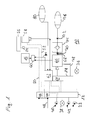
- FIG. 1 shows a parking brake system.
- the illustrated parking brake system 10 comprises a control unit 12, a pilot control group 14 and a parking brake cylinder 16, which is shown by way of example for all parking brake cylinders 16 of a parking brake system.
- the control unit 12 is equipped with a connection 48 to a vehicle bus (CAN) and connected to a button 22, a emergency release 40 and a parking brake 42.
- the control unit 12 is able to directly control a valve device 62 and a further valve device 64 of the pilot control group 14 in order to control the functions of the parking brake system 10.
- the parking brake system 10 is electrically switchable via the pilot control group 14 and is supplied via a compressed air supply 78 with the necessary pressure means for actuating the illustrated parking brake cylinder 16.
- the compressed air is supplied to the parking brake cylinder 16 via a relay valve 66 and a shuttle valve 60, wherein the relay valve 66 is controlled by the further valve device 64 of the pilot control group 14.
- the pressure supply of the parking brake cylinder 16 is interrupted, for example by a line break between the relay valve 66 and the shuttle valve 60, the pressure in the parking brake cylinder 16 can be maintained via an emergency release device 34, which is switched by the valve device 62. Due to the short switching times of the two valve devices 62, 64 a rapid response by switching the pressure supply of the parking brake cylinder 16 is possible.
- the pressure supply of the emergency release device 34 is ensured via a compressed air reservoir 80 regardless of the compressed air supply 78. Furthermore, the emergency release device 34 has its own not shown venting option.
- the valve device 62 furthermore comprises a pressure output for a trailer control module 58, which is also coupled to an EBS control unit 46 via a connection 52 of the service brake.
- the EBS controller 46 is also coupled to the vehicle bus via port 48 and continues to control a trailer 56 via a junction box 54, which is coupled via a terminal 50 of the trailer with the EBS control unit 46.
- the control unit 12 is able to control a brake light 36 and a warning signal 38.
- the shuttle valve 60 forwards the higher of the two applied input pressures to the parking brake cylinder 16, that is, either the pressure provided by the emergency release device 34 or the normal supply pressure provided via the relay valve 66.
- the relay valve 66 has a venting outlet 68, to which a connection module 74, which essentially comprises a check valve, can be connected via a compressed-air line connector 70.
- the connection module 74 prevents venting of the parking brake cylinder 16 via the vent outlet 68 and, if an external compressed air reservoir 76 is coupled via another Druck Kunststoff fürsstecker 72 with the connection module 74, used to release the parking brake of the vehicle by venting the parking brake cylinder 16 without the vehicle Having to put into operation itself, which may be advantageous for example when towing a defective vehicle or in a workshop.
- Both the connection module 74 and the external compressed air reservoir 76 are shown in the coupled state with the parking brake system 10.
- the control unit 12 includes an emergency release wiring 44, which operates largely independently of the other components of the control unit 12 in order to open the parking brake by pressing the emergency release device 34 even in the event of a defect-related failure of the control unit 12.
- the compressed air line plug 70 may be readily accessible to the vehicle for this purpose.
- the presence of the connection module 74 can be detected, for example, via a pressure sensor, not shown, at the vent outlet 68 or by closing a contact during assembly of the connection module to the compressed air line connector 70.
- a signal generated in this manner may temporarily override or suppress control signals for the parking brake system 10 generated by the controller 12 to prevent damage to the parking brake system 10 due to improper loading and to permit trouble-free external venting. It is conceivable, even at the venting possibility of the emergency release device 34 to provide a connection option for external ventilation of the parking brake.
- FIG. 2 shows a schematic structure of a control device for a parking brake system with possible connections.
- the dargixie control unit 12 includes a volatile memory 30 and a non-volatile memory 32, in each of which different data can be stored.
- a test routine to be executed can take place in the volatile memory 30 or the necessary data can be temporarily stored, while in the non-volatile memory 32 only the final result of the test routine can be stored. In this way, the flow of the test routine can be accelerated because time-consuming write and erase cycles of the nonvolatile memory 32 are reduced.
- the control unit 12 further has an energy store 84, for example in the form of a simple capacitor, and via connections to an ignition 20 and a continuous voltage 82 and to the vehicle bus 48.
- the control unit 12 is during a follow-up time after switching off the ignition 20 via the Continuous voltage 82 supplied with energy.
- the energy store 84 may be designed to ensure a controlled operation of the controller 12 during the follow-up time even in the event of a power failure.
- the control unit 12 is coupled to the pilot control group 14, not shown in this figure, via a control connection 86, via which the various valve devices 60, 62 of the pilot control group 14 can be activated by the control unit 12.
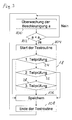
- FIG. 3 shows a flowchart for illustrating a first test routine.
- the starting point is the monitoring of the acceleration a of the vehicle in step 100.
- the monitoring of the vehicle acceleration a is carried out by default, for example in the context of an ESP control loop, or by the control unit 12. If the monitoring in the context of an ESP control loop, for example If a negative acceleration threshold value a g is exceeded, a step 102-Yes is generated, which initiates the start of the test routine in step 104.
- the generated signal as a wake-up signal for the Control unit 12 and the required for performing a test routine components of the control unit 12 may be used.
- the first step after the end of the test routine 18 is step 106 and includes storing the final result of the first test routine 18.
- the partial tests 24, 26, 28 of the first test routine 18 are executed one after the other, ending at the end of each partial test 24, 26, 28 Ending the first test routine 18 is possible if the result of the partial test 24, 26, 28 already carried out already anticipates the final result of the entire first test routine 18. If, for example, a defect of the parking brake system has been detected in the first partial test 24, the execution of the second partial test 26 and the third partial test 28 can be dispensed with since the result of the first test routine 18 is already established and the parking brake system 10 is defective.
- the first partial test 24 it can be provided, for example, that it is checked whether the negative acceleration a ascertained in step 102 can be traced back to a driver's request, for example to the actuation of the service brake. If this is the case, then the first test routine 18 can be aborted, since obviously no defect of the parking brake system 10 is present.
- the second partial test 26 may include, for example, pressure measurements in the various line sections of the parking brake system 10 to determine whether the measured negative acceleration a is caused by the parking brake.
- the third part test 28 may include, for example, a functional check of various components of the parking brake system 10, wherein in particular electrical and mechanical components can be controlled without actually operating the parking brake system 10, for example, to determine electrical line defects or electrical short circuits.
- a check of the trailer brake is part of the first test routine 18.
- the first test routine 18 is event-controlled, wherein according to the illustrated flow diagram, depending on the result of an already performed partial test 24, 26, one or more partial tests 26, 28 still to be performed are skipped.
- the first test routine 18 can then either according to the Flowchart in FIG. 1 be terminated or continued in a manner not shown with a later to be executed partial examination.
- the result of the first part check 24 may cause the second part check 26 to go over and the first test routine 18 to continue with the third part check 28, or the result of the first part check 24 may cause the first test routine 18 to finish.
- a defect of the parking brake system 10 is fixed, it can be attempted, for example via the emergency release device 34, to reduce the delay effect a which has occurred, for example by supplying air again.
- it may be provided to ventilate the trailer control module 58 via its pneumatic input, to send a release message to the trailer 56 via the connector 54 of the trailer and / or the CAN bus, to any unwanted braking effect of the parking brake to eliminate the trailer 56.
- the control unit 12 can also activate the brake light 36 to warn subsequent vehicles, issue a warning signal 38 to the driver and send an error message for further processing in other vehicle computers via the connection 48 of the vehicle bus (CAN).
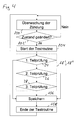
- FIG. 4 shows a flowchart for illustrating a second and third test routine. This in FIG. 4 shown flow diagram differs in particular by the steps 100 'and 102' from the FIG. 3 already known flowchart.
- step 100 ' the ignition of the vehicle is monitored and, starting from step 102', a second test routine 18 'or a third test routine 18 "is started in step 104, when the state of the ignition changes, step 102'-yes Whether the ignition is turned on or off
- the second test routine 18 ' is started, while by turning off the ignition, the third test routine 18 "is started.
- Both the second test routine 18 'and the third Test routine 18 " analogous to the first test routine 18, comprise partial tests 24, 26, 28 which are executed one after the other, but the content and scope as well as the number of partial tests 24, 26, 28 to be executed may vary between the individual test routines 18, 18 ', 18". differ.
- the wheel speed may be taken into account to ensure that the vehicle is stationary while this condition does not enter the first test routine
- Embodiments regarding the event-controlled first test routine 18 FIG. 1 are transferable to the second test routine 18 'and the third test routine 18 ".
- FIG. 5 shows a flowchart illustrating a fourth test routine. That in the FIG. 5 The flow chart shown comprises a fourth test routine 18 "'which, in contrast to that of FIGS Figures 3 and 4 already known test routines 18, 18 ', 18 "in steps 100", 102 "by monitoring a button in step 102" -Ja is started. Also in FIG. 5 shown fourth test routine 18 "'includes a plurality of successive to be executed part checks 24, 26, 28, which in number and content, for example, those of the Figures 3 and 4 In the fourth test routine 18 ", the first partial test 24 may in particular comprise a check of a stored final result, wherein it is checked in dependence on a previously determined defect stored as a final result the defect is corrected. This can be advantageous in particular for the maintenance of the vehicle. The statements regarding the event-controlled first test routine 18 FIG. 1 are transferable to the fourth test routine 18 "'.
Abstract
Description
Die Erfindung betrifft ein Verfahren zum Betreiben eines elektrisch gesteuerten Feststellbremssystems eines Fahrzeugs, insbesondere eines Nutzfahrzeugs, mit einem elektronischen Steuergerät, einer elektropneumatischen Vorsteuergruppe und einem Feststellbremszylinder.The invention relates to a method for operating an electrically controlled parking brake system of a vehicle, in particular a utility vehicle, with an electronic control unit, an electropneumatic pilot control group and a parking brake cylinder.
Die Erfindung betrifft weiterhin ein elektronisches Steuergerät, das zur Durchführung eines erfindungsgemäßen Verfahrens eingerichtet ist.The invention further relates to an electronic control unit which is set up for carrying out a method according to the invention.
Die Verbesserung der Effizienz von Fahrzeugen, insbesondere von Nutzfahrzeugen, ist sowohl unter ökonomischen als auch unter ökologischen Aspekten vorteilhaft, wobei insbesondere der Energieverbrauch beim Betrieb des Fahrzeugs gesenkt werden soll. Dabei ist darauf zu achten, dass die Verbesserung der Effizienz nicht zu Lasten der Betriebssicherheit erfolgt. Neben der Möglichkeit direkt den Wirkungsgrad des das Fahrzeug antreibenden Antriebsmotors zu verbessern, besteht die Möglichkeit auf der Verbraucherseite bei anderen Teilsystemen, zum Beispiel einem Feststellbremssystem, die für den Betrieb notwendige Energie zu reduzieren, um auf diese Weise die Energieeffizienz des Fahrzeugs zu erhöhen.The improvement of the efficiency of vehicles, in particular of commercial vehicles, is advantageous both from an economic and ecological point of view, in particular by reducing the energy consumption during operation of the vehicle. It is important to ensure that the improvement in efficiency is not at the expense of operational safety. In addition to the possibility directly to improve the efficiency of the drive motor driving the vehicle, there is the possibility on the consumer side in other subsystems, for example a parking brake system to reduce the energy required for operation, in order to increase the energy efficiency of the vehicle.
Der vorliegenden Erfindung liegt daher die Aufgabe zugrunde, ein energiesparendes und zugleich sicheres Verfahren zum Betreiben einer elektrisch gesteuerten Feststellbremse bereitzustellen.The present invention is therefore based on the object to provide an energy-saving and at the same time safe method for operating an electrically controlled parking brake.
Diese Aufgabe wird mit den Merkmalen des unabhängigen Anspruchs gelöst.This object is achieved with the features of the independent claim.
Vorteilhafte Ausführungsformen der Erfindung sind in den abhängigen Ansprüchen angegeben.Advantageous embodiments of the invention are indicated in the dependent claims.
Die Erfindung baut auf dem gattungsgemäßen Verfahren dadurch auf, dass ein Beschleunigungswert a des Fahrzeugs überwacht wird und bei Unterschreitung eines vorgebbaren negativen Beschleunigungsschwellwertes ag das elektrisch gesteuerte Feststellbremssystem durch eine erste Testroutine überprüft wird. Auf diese Weise kann eine nicht zyklische Überwachung beim Betrieb der Feststellbremse erfolgen, die eine Überprüfung des Feststellbremssystems an das Vorliegen eines negativen Beschleunigungswertes a < ag koppelt. Die Überprüfung der Feststellbremse wird also verdachtsabhängig beziehungsweise ereignisgesteuert gestartet, im Gegensatz zu einer sonst üblichen verdachtsunabhängigen Überprüfung, die beispielsweise zyklisch gesteuert sein kann. Dies spart Energie und ergibt somit eine Effizienzsteigerung, da die Überprüfung der Feststellbremse seltener und nur bei Vorliegen eines Verdachts auf einen Defekt erfolgt. Die Überprüfung der Funktion der Feststellbremse an sich ist vorteilhaft, da die Feststellbremse konstruktionsbedingt bei einem Defekt schließt und dabei eine entsprechende Bremswirkung auf das Fahrzeug ausübt, die zu Auffahrunfällen aufgrund der spontanen Verzögerung führen kann.The invention is based on the generic method in that an acceleration value a of the vehicle is monitored and when a predeterminable negative acceleration threshold value a g is exceeded, the electrically controlled parking brake system is checked by a first test routine. In this way, a non-cyclical monitoring during operation of the parking brake can take place, which couples a check of the parking brake system to the presence of a negative acceleration value a <a g . The check of the parking brake is thus started depending on the suspicion or event-controlled, in contrast to an otherwise usual suspicion-independent review, which can be cyclically controlled, for example. This saves energy and thus results in an increase in efficiency, since the check of the parking brake is less frequent and occurs only in the presence of a suspected defect. The verification of the function of the parking brake itself is advantageous because the parking brake by design closes at a defect and thereby exerts a corresponding braking effect on the vehicle, which can lead to rear-end collisions due to the spontaneous deceleration.
Nützlicherweise kann vorgesehen sein, dass das elektrisch gesteuerte Feststellbremssystem nach dem Ausschalten einer Zündung durch eine zweite Testroutine überprüft wird. Das Ausschalten der Zündung erfolgt üblicherweise bei einem abgestellten Fahrzeug, so dass die zweite Testroutine gegenüber der ersten Testroutine anders aufgebaut sein kann und beispielsweise auch die Überprüfung von Teilen der Feststellbremse umfassen kann, die während der Fahrt nicht getestet werden können.Usefully it can be provided that the electrically controlled parking brake system is checked after switching off an ignition by a second test routine. Switching off the ignition is usually carried out at a parked vehicle, so that the second test routine compared to the first test routine can be structured differently and may include, for example, the verification of parts of the parking brake, which can not be tested while driving.
Vorteilhafterweise kann vorgesehen sein, dass das elektrisch gesteuerte Feststellbremssystem nach dem Einschalten einer Zündung durch eine dritte Testroutine überprüft wird. Auch nach dem Einschalten der Zündung, das heißt bei einer Wiederinbetriebnahme eines zunächst abgestellten Fahrzeugs, ist das Überprüfen der Feststellbremse durch die dritte Testroutine vorteilhaft, die wiederum anders als die erste Testroutine und/oder die zweite Testroutine aufgebaut sein kann.Advantageously, it can be provided that the electrically controlled parking brake system after switching on an ignition by a third test routine is checked. Even after switching on the ignition, that is, when restarting a first parked vehicle, the verification of the parking brake by the third test routine is advantageous, which in turn may be constructed differently than the first test routine and / or the second test routine.
Es kann vorgesehen sein, dass das elektrisch gesteuerte Feststellbremssystem nach dem manuellen Betätigen eines Tasters durch eine vierte Testroutine überprüft wird. Auf diese Weise kann bei Bedarf eine Überprüfung des Feststellbremssystems eingeleitet werden, was beispielsweise nach einer Instandsetzung aufgrund eines vorangegangenen Defektes zur Funktionsüberprüfung vorteilhaft sein kann.It can be provided that the electrically controlled parking brake system is checked after manually pressing a button by a fourth test routine. In this way, if necessary, a check of the parking brake system can be initiated, which may be advantageous, for example, after a repair due to a previous defect for functional check.
Vorzugsweise kann vorgesehen sein, dass ein Endergebnis der Testroutine gespeichert wird. Durch das Sichern des Endergebnisses kann beispielsweise zu Dokumentationszwecken eine spätere Auswertung erfolgen. Des Weiteren können gespeicherte Endergebnisse zur Modifizierung später durchgeführter Testroutinen herangezogen werden.Preferably, it can be provided that an end result of the test routine is stored. By saving the final result, for example, a later evaluation can be made for documentation purposes. Furthermore, stored final results can be used to modify later performed test routines.
Besonders bevorzugt ist, dass die Testroutine Teilprüfungen umfasst, die nacheinander durchgeführt werden, dass die Testroutine nach einer Teilprüfung abgebrochen wird, wenn ein Ergebnis dieser Teilprüfung das Endergebnis der Testroutine festlegt, und dass das Ergebnis als Endergebnis übernommen wird. Auf diese Weise kann die zur Durchführung der Testroutine benötigte Zeit reduziert werden, so dass der notwendige Energieaufwand weiter reduzierbar ist. Die Testroutine ist also ereignisgesteuert, wobei je nach Ergebnis einer bereits durchgeführten Teilprüfung eine oder mehrere noch auszuführende Teilprüfungen übergangen werden. Es ist auch denkbar, in Abhängigkeit von einem Ergebnis einer bereits durchgeführten Teilprüfung eine oder mehrere noch auszuführende Teilprüfungen zu modifizieren.It is particularly preferred that the test routine comprises sub-tests, which are carried out in succession, that the test routine is aborted after a partial test, if a result of this sub-test determines the final result of the test routine, and that the result is adopted as the final result. In this way, the time required to carry out the test routine can be reduced, so that the necessary expenditure of energy can be further reduced. The test routine is therefore event-driven, whereby, depending on the result of an already performed partial test, one or more partial tests still to be performed are skipped. It is also conceivable, depending on a result of a partial test already carried out, to modify one or more partial tests still to be carried out.
Weiterhin kann vorgesehen sein, dass Daten der Testroutine in flüchtigem Speicher vorgehalten werden und das Endergebnis in nicht flüchtigen Speicher geschrieben wird. Da ein nicht flüchtiger Speicher im Vergleich zu flüchtigem Speicher träge ist, kann die Dauer der Testroutine verkürzt werden, wenn lediglich das Endergebnis in nicht flüchtigen Speicher geschrieben wird.Furthermore, it can be provided that data of the test routine are stored in volatile memory and the final result is written in non-volatile memory. Because nonvolatile memory is sluggish compared to volatile memory, The duration of the test routine can be shortened if only the final result is written in non-volatile memory.
Insbesondere kann vorgesehen sein, dass der Feststellbremszylinder über eine Notlösevorrichtung belüftet wird, wenn ein Fehler des elektrischen Feststellbremssystems erkannt wird. Auf diese Weise kann der Betrieb des Feststellbremssystems auch bei einem Defekt aufrechterhalten werden, wobei üblicherweise die Notlösevorrichtung ein Einfallen der Feststellbremse während der Fahrt vermeiden soll. Das Schalten der Notlösevorrichtung kann bereits vor Abschluss der Testroutine erfolgen und insbesondere bei Erkennung einer Bremswirkung a < ag ohne entsprechenden Fahrzeug- oder Fahrerwunsch auch prophylaktisch vor der Erkennung eines Defekts in dem Feststellbremssystem erfolgen, um die Reaktionszeit des Systems zu verringern.In particular, it can be provided that the parking brake cylinder is ventilated via an emergency release device when a fault of the electric parking brake system is detected. In this way, the operation of the parking brake system can be maintained even in the event of a defect, and usually the emergency release device should avoid a collapse of the parking brake while driving. The switching of the emergency release device can already be done before completion of the test routine and in particular on detection of a braking effect a <a g without appropriate vehicle or driver request also prophylactically done before detecting a defect in the parking brake system to reduce the reaction time of the system.
Nützlicherweise kann vorgesehen sein, dass ein Bremslicht des Fahrzeugs aktiviert wird, wenn ein Fehler des elektrischen Feststellbremssystems erkannt wird. Durch das Einschalten des Bremslichtes kann der Fahrer eines nachfolgenden Fahrzeugs von der eventuell einsetzenden Verzögerung informiert werden, so dass Auffahrunfälle verhindert werden. Das Bremslicht kann nach dem Auslösen der Notlösefunktion wieder ausgeschaltet werden, wenn keine unerwünschte Verzögerung durch die Feststellbremse mehr vorliegt.Usefully, it can be provided that a brake light of the vehicle is activated when a fault of the electric parking brake system is detected. By switching on the brake light, the driver of a subsequent vehicle can be informed of the eventual delay, so that rear-end collisions are prevented. The brake light can be switched off again after the triggering of the emergency release function if there is no longer any undesired deceleration due to the parking brake.
Es kann vorgesehen sein, dass eine Wiederinbetriebnahme des Fahrzeugs nach dem Einschalten einer Zündung unterbunden wird, wenn ein Fehler des elektrischen Feststellbremssystems erkannt wird. Um eine Beschädigung des Feststellbremssystems durch Überbelastung zu verhindern, kann das Anfahren des Fahrzeugs unterbunden werden, wenn die Feststellbremse durch einen Defekt nicht lösbar ist. Weiterhin ist dieses Vorgehen unter Sicherheitsaspekten vorteilhaft, da ein Defekt des Feststellbremssystems möglicherweise sicherheitsrelevante Funktionen des Fahrzeugs negativ beeinflusst.It can be provided that restarting the vehicle after switching on an ignition is inhibited if a fault of the electric parking brake system is detected. To prevent damage to the parking brake system by overloading, the start of the vehicle can be prevented if the parking brake is not solvable by a defect. Furthermore, this approach is advantageous in terms of safety, since a failure of the parking brake system may adversely affect safety-related functions of the vehicle.
Es ist jedoch denkbar, dass bei Erkennung einer Notsituation eine Wiederinbetriebnahme des Fahrzeugs auch bei einem erkannten Defekt des elektrischen Feststellbremssystems erlaubt wird. Eine solche Notsituation kann beispielsweise dann vorliegen, wenn das Fahrzeug auf einem Bahnübergang zum Stehen kommt und unbedingt aus dieser Position entfernt werden muss. Die Notsituation kann beispielsweise basierend auf GPS-Daten festgestellt werden.However, it is conceivable that upon detection of an emergency situation, a restart of the vehicle is allowed even if a detected defect of the electric parking brake system. Such an emergency situation can be present, for example, when the vehicle comes to a level crossing to a stop and must be removed from this position necessarily. The emergency situation can be determined, for example, based on GPS data.
Vorteilhafterweise kann vorgesehen sein, dass ein Warnsignal an den Fahrer ausgegeben wird, wenn ein Fehler des elektrischen Feststellbremssystems erkannt wird. Durch ein entsprechendes Warnsignal kann der Fahrer des Fahrzeugs auf die notwendigen Instandsetzungsarbeiten aufmerksam gemacht werden, die durch den Defekt des Feststellbremssystems verursacht werden. Die Ausgabe des Warnsignals kann beispielsweise optisch oder akustisch erfolgen.Advantageously, it can be provided that a warning signal is output to the driver when a fault of the electric parking brake system is detected. By a corresponding warning signal, the driver of the vehicle can be made aware of the necessary repair work, which is caused by the defect of the parking brake system. The output of the warning signal can be made, for example, optically or acoustically.
Die vorliegende Erfindung wird nun mit Bezug auf die begleitenden Zeichnungen anhand bevorzugter Ausführungsformen beispielhaft erläutert.The present invention will now be described by way of example with reference to the accompanying drawings by way of preferred embodiments.
Es zeigen:
- Figur 1
- ein Feststellbremssystem;
- Figur 2
- einen schematischen Aufbau eines Steuergerätes für ein Feststell- bremssystem mit möglichen Anschlüssen;
- Figur 3
- ein Flussdiagramm zur Veranschaulichung einer ersten Testroutine;
- Figur 4
- ein Flussdiagramm zur Veranschaulichung einer zweiten bezie- hungsweise einer dritten Testroutine; und
- Figur 5
- ein Flussdiagramm zur Veranschaulichung einer vierten Testroutine.
- FIG. 1
- a parking brake system;
- FIG. 2
- a schematic structure of a control device for a parking brake system with possible connections;
- FIG. 3
- a flowchart illustrating a first test routine;
- FIG. 4
- a flowchart illustrating a second or a third test routine; and
- FIG. 5
- a flowchart illustrating a fourth test routine.
In den folgenden Zeichnungen bezeichnen gleiche Bezugszeichen gleiche oder gleichartige Teile.In the following drawings, like reference characters designate like or similar parts.
In
Die in der vorstehenden Beschreibung, in den Zeichnungen sowie in den Ansprüchen offenbarten Merkmale der Erfindung können sowohl einzeln als auch in beliebiger Kombination für die Verwirklichung der Erfindung wesentlich sein.The features of the invention disclosed in the foregoing description, in the drawings and in the claims may be essential to the realization of the invention both individually and in any combination.
- 1010
- FeststellbremssystemParking brake system
- 1212
- Steuergerätcontrol unit
- 1414
- Vorsteuergruppepilot group
- 1616
- FeststellbremszylinderParking brake cylinder
- 1818
- erste Testroutinefirst test routine
- 18'18 '
- zweite Testroutinesecond test routine
- 18"18 "
- dritte Testroutinethird test routine
- 18"'18 ' "
- vierte Testroutinefourth test routine
- 2020
- Zündungignition
- 2222
- Tasterbutton
- 2424
- 1.Teilprüfung1.Teilprüfung
- 2626
- 2.Teilprüfung2.Teilprüfung
- 2828
- 3.Teilprüfung3.Teilprüfung
- 3030
- flüchtiger Speichervolatile memory
- 3232
- nicht flüchtiger Speichernon-volatile memory
- 3434
- Notlösevorrichtungemergency release
- 3636
- Bremslichtstoplight
- 3838
- Warnsignalwarning
- 4040
- NotlösegeberNotlösegeber
- 4242
- FeststellbremsgeberParking brake donors
- 4444
- NotlöseverdrahtungNotlöseverdrahtung
- 4646
- EBS-SteuergerätEBS control unit
- 4848
- Anschluss CANConnection CAN
- 5050
- Anschluss AnhängerConnection trailer
- 5252
- Anschluss BetriebsbremseConnection service brake
- 5454
- Anschlussdosejunction box
- 5656
- Anhängerpendant
- 5858
- AnhängersteuermodulTrailer control module
- 6060
- Wechselventilshuttle valve
- 6262
- Ventileinrichtungvalve means
- 6464
- weitere Ventileinrichtungfurther valve device
- 6666
- Relaisventilrelay valve
- 6868
- Entlüftungsausgangbleed outlet
- 7070
- DruckluftleitungssteckerCompressed air line connector
- 7272
- weiterer Druckluftleitungssteckeradditional compressed air line connector
- 7474
- Anschlussmodulconnection module
- 7676
- DruckluftvorratCompressed air supply
- 7878
- DruckluftversorgungAir Supply
- 8080
- DruckluftvorratsbehälterCompressed air reservoir
- 8282
- Dauerspannungcontinuous voltage
- 8484
- Energiespeicherenergy storage
- 8686
- Steueranschlusscontrol connection
- 100100
- Überwachung der Beschleunigung aMonitoring the acceleration a
- 100'100 '
- Überwachen der ZündungMonitor the ignition
- 100"100 '
- Überwachen eines TastersMonitoring a button
- 102102
- a < ag?a <a g ?
- 102'102 '
- Zustand geändert?State changed?
- 102"102 '
- Taster betätigt?Button pressed?
- 104104
- Start der TestroutineStart of the test routine
- 106106
- Speichernto save
- 108108
- Ende der TestroutineEnd of the test routine
Claims (13)
Applications Claiming Priority (1)
| Application Number | Priority Date | Filing Date | Title |
|---|---|---|---|
| DE102009022228A DE102009022228A1 (en) | 2009-05-20 | 2009-05-20 | Method and control device for operating an electrically controlled parking brake system of a vehicle |
Publications (2)
| Publication Number | Publication Date |
|---|---|
| EP2256012A1 true EP2256012A1 (en) | 2010-12-01 |
| EP2256012B1 EP2256012B1 (en) | 2012-01-25 |
Family
ID=42334061
Family Applications (1)
| Application Number | Title | Priority Date | Filing Date |
|---|---|---|---|
| EP10163279A Active EP2256012B1 (en) | 2009-05-20 | 2010-05-19 | Method and control device for checking an electrically controlled handbrake for a vehicle |
Country Status (3)
| Country | Link |
|---|---|
| EP (1) | EP2256012B1 (en) |
| AT (1) | ATE542722T1 (en) |
| DE (1) | DE102009022228A1 (en) |
Cited By (1)
| Publication number | Priority date | Publication date | Assignee | Title |
|---|---|---|---|---|
| CN107921942A (en) * | 2015-07-27 | 2018-04-17 | 沃尔沃卡车集团 | Include the braking equipment of composite braking actuator |
Citations (12)
| Publication number | Priority date | Publication date | Assignee | Title |
|---|---|---|---|---|
| EP0924128A1 (en) * | 1997-12-16 | 1999-06-23 | Toyota Jidosha Kabushiki Kaisha | Method and apparatus for diagnosing electrically operated brake without manual operation of brake operating member |
| DE19858583A1 (en) * | 1998-12-18 | 2000-06-21 | Knorr Bremse Systeme | Procedure for controlling brake installation of vehicle has detected estimated values compared with threshold values and estimated value does not come into effect when threshold exceeded |
| EP1439102A1 (en) * | 2003-01-17 | 2004-07-21 | Delphi Technologies, Inc. | Apparatus and method for controlling an electric park brake |
| WO2004076254A1 (en) * | 2003-02-24 | 2004-09-10 | Bendix Commercial Vehicle Systems Llc | Electro-pneumatic latching valve system |
| WO2004106131A1 (en) * | 2003-05-28 | 2004-12-09 | Lucas Automotive Gmbh | Method and system for controlling a braking system equipped with an electric parking brake |
| DE102005024343A1 (en) * | 2004-05-31 | 2006-01-05 | Advics Co., Ltd., Kariya | Brake device abnormality determining apparatus for vehicle has abnormality determining unit that detects presence or absence of abnormality in parking brake mechanism based on whether parking brake mechanism exists in preset condition |
| WO2006010735A1 (en) * | 2004-07-23 | 2006-02-02 | Continental Teves Ag & Co. Ohg | Brake device for a vehicle with an electric parking brake system and corresponding control method |
| DE102004037303A1 (en) * | 2004-07-31 | 2006-02-16 | Robert Bosch Gmbh | Vehicle electrical parking brake test procedure compares brake pressure rise gradient during second application to reference value to check lock strength |
| WO2006045841A1 (en) * | 2004-10-29 | 2006-05-04 | Continental Teves Ag & Co. Ohg | Method for operating a parking brake that can be actuated by means of an external force |
| DE102007005871B3 (en) * | 2007-02-06 | 2008-07-03 | Siemens Ag | Vehicle wheel baking method, involves comparing measuring value and predetermined measuring reference value, and adjusting braking force by measuring value depending upon exceeding or falling of predetermined measuring reference value |
| WO2008092683A1 (en) * | 2007-01-31 | 2008-08-07 | Knorr-Bremse Systeme für Nutzfahrzeuge GmbH | Brake system and method for controlling a brake system for a commercial vehicle |
| DE102007014427A1 (en) * | 2007-03-22 | 2008-09-25 | Knorr-Bremse Systeme für Nutzfahrzeuge GmbH | Electric parking brake system for a commercial vehicle and operating method |
Family Cites Families (1)
| Publication number | Priority date | Publication date | Assignee | Title |
|---|---|---|---|---|
| DE102007034799A1 (en) * | 2007-07-23 | 2009-02-05 | Siemens Ag | Method for statically checking a brake system of a vehicle |
-
2009
- 2009-05-20 DE DE102009022228A patent/DE102009022228A1/en not_active Ceased
-
2010
- 2010-05-19 EP EP10163279A patent/EP2256012B1/en active Active
- 2010-05-19 AT AT10163279T patent/ATE542722T1/en active
Patent Citations (12)
| Publication number | Priority date | Publication date | Assignee | Title |
|---|---|---|---|---|
| EP0924128A1 (en) * | 1997-12-16 | 1999-06-23 | Toyota Jidosha Kabushiki Kaisha | Method and apparatus for diagnosing electrically operated brake without manual operation of brake operating member |
| DE19858583A1 (en) * | 1998-12-18 | 2000-06-21 | Knorr Bremse Systeme | Procedure for controlling brake installation of vehicle has detected estimated values compared with threshold values and estimated value does not come into effect when threshold exceeded |
| EP1439102A1 (en) * | 2003-01-17 | 2004-07-21 | Delphi Technologies, Inc. | Apparatus and method for controlling an electric park brake |
| WO2004076254A1 (en) * | 2003-02-24 | 2004-09-10 | Bendix Commercial Vehicle Systems Llc | Electro-pneumatic latching valve system |
| WO2004106131A1 (en) * | 2003-05-28 | 2004-12-09 | Lucas Automotive Gmbh | Method and system for controlling a braking system equipped with an electric parking brake |
| DE102005024343A1 (en) * | 2004-05-31 | 2006-01-05 | Advics Co., Ltd., Kariya | Brake device abnormality determining apparatus for vehicle has abnormality determining unit that detects presence or absence of abnormality in parking brake mechanism based on whether parking brake mechanism exists in preset condition |
| WO2006010735A1 (en) * | 2004-07-23 | 2006-02-02 | Continental Teves Ag & Co. Ohg | Brake device for a vehicle with an electric parking brake system and corresponding control method |
| DE102004037303A1 (en) * | 2004-07-31 | 2006-02-16 | Robert Bosch Gmbh | Vehicle electrical parking brake test procedure compares brake pressure rise gradient during second application to reference value to check lock strength |
| WO2006045841A1 (en) * | 2004-10-29 | 2006-05-04 | Continental Teves Ag & Co. Ohg | Method for operating a parking brake that can be actuated by means of an external force |
| WO2008092683A1 (en) * | 2007-01-31 | 2008-08-07 | Knorr-Bremse Systeme für Nutzfahrzeuge GmbH | Brake system and method for controlling a brake system for a commercial vehicle |
| DE102007005871B3 (en) * | 2007-02-06 | 2008-07-03 | Siemens Ag | Vehicle wheel baking method, involves comparing measuring value and predetermined measuring reference value, and adjusting braking force by measuring value depending upon exceeding or falling of predetermined measuring reference value |
| DE102007014427A1 (en) * | 2007-03-22 | 2008-09-25 | Knorr-Bremse Systeme für Nutzfahrzeuge GmbH | Electric parking brake system for a commercial vehicle and operating method |
Cited By (2)
| Publication number | Priority date | Publication date | Assignee | Title |
|---|---|---|---|---|
| CN107921942A (en) * | 2015-07-27 | 2018-04-17 | 沃尔沃卡车集团 | Include the braking equipment of composite braking actuator |
| CN107921942B (en) * | 2015-07-27 | 2021-06-04 | 沃尔沃卡车集团 | Brake apparatus including hybrid brake actuator |
Also Published As
| Publication number | Publication date |
|---|---|
| EP2256012B1 (en) | 2012-01-25 |
| ATE542722T1 (en) | 2012-02-15 |
| DE102009022228A1 (en) | 2010-11-25 |
Similar Documents
| Publication | Publication Date | Title |
|---|---|---|
| EP2146882B1 (en) | Parking brake device of a vehicle with emergency release function and method for operating such a parking brake device | |
| DE102007037346C5 (en) | Control unit for a brake system of a commercial vehicle and method for controlling a brake system | |
| EP2229302B2 (en) | Brake system for a vehicle, and brake pedal device for such a brake system | |
| DE102008018622B4 (en) | Method for operating a brake system and brake system for a commercial vehicle | |
| EP2190706B1 (en) | Valve arrangement for controlling a brake system of a trailer vehicle | |
| EP3755589B1 (en) | Electropneumatic equipment of a vehicle | |
| DE102007052439A1 (en) | Driver assistance system | |
| EP2108553A2 (en) | Immobilising brake with test capabilities and method for executing a test function | |
| EP3292031A1 (en) | Method for operating a parking brake system for utility vehicles, and device therefor | |
| EP0535392B1 (en) | Diagnostic method for an electronically controlled fluid pressure brake installation of a vehicle | |
| EP3829944B1 (en) | Method for the automated electronic control of a brake system in a utility vehicle having anti-lock braking protection | |
| EP2256012B1 (en) | Method and control device for checking an electrically controlled handbrake for a vehicle | |
| WO2009043405A1 (en) | Brake system and electronic air treatment unit for compressed air brake systems having integrated timer and temperature sensor | |
| WO2017089521A1 (en) | Method and device for operating a brake system for a vehicle and brake system | |
| EP1515882B1 (en) | Electropneumatic trailer brake system and method for operating the same | |
| EP1764276A1 (en) | Vehicle air braking system | |
| DE102008027730B4 (en) | An electrically controlled parking brake system and method for operating an electrically controlled parking brake system | |
| EP1521091B1 (en) | Monitoring of power supply network | |
| EP4363284A1 (en) | Brake system for a utility vehicle, and method for testing the functionality of a select-high valve of the brake system | |
| DE102021118006A1 (en) | Method for checking the function of a fluid-operated electronic brake system in a vehicle | |
| DE102006027374A1 (en) | Motor vehicle parking brake, acting on at least one wheel, has an actuator structured to test if input data are received within a test interval to give an automatic emergency brake action | |
| DE102016201222A1 (en) | Method for monitoring a vehicle compressed air system |
Legal Events
| Date | Code | Title | Description |
|---|---|---|---|
| PUAI | Public reference made under article 153(3) epc to a published international application that has entered the european phase |
Free format text: ORIGINAL CODE: 0009012 |
|
| AK | Designated contracting states |
Kind code of ref document: A1 Designated state(s): AL AT BE BG CH CY CZ DE DK EE ES FI FR GB GR HR HU IE IS IT LI LT LU LV MC MK MT NL NO PL PT RO SE SI SK SM TR |
|
| AX | Request for extension of the european patent |
Extension state: BA ME RS |
|
| 17P | Request for examination filed |
Effective date: 20110601 |
|
| RIC1 | Information provided on ipc code assigned before grant |
Ipc: B60T 13/74 20060101AFI20110624BHEP Ipc: B60T 17/22 20060101ALI20110624BHEP Ipc: B60T 8/00 20060101ALI20110624BHEP Ipc: B60T 13/66 20060101ALI20110624BHEP |
|
| GRAP | Despatch of communication of intention to grant a patent |
Free format text: ORIGINAL CODE: EPIDOSNIGR1 |
|
| RIN1 | Information on inventor provided before grant (corrected) |
Inventor name: HILBERER, EDUARD |
|
| GRAS | Grant fee paid |
Free format text: ORIGINAL CODE: EPIDOSNIGR3 |
|
| GRAA | (expected) grant |
Free format text: ORIGINAL CODE: 0009210 |
|
| AK | Designated contracting states |
Kind code of ref document: B1 Designated state(s): AL AT BE BG CH CY CZ DE DK EE ES FI FR GB GR HR HU IE IS IT LI LT LU LV MC MK MT NL NO PL PT RO SE SI SK SM TR |
|
| REG | Reference to a national code |
Ref country code: GB Ref legal event code: FG4D Free format text: NOT ENGLISH |
|
| REG | Reference to a national code |
Ref country code: CH Ref legal event code: EP |
|
| REG | Reference to a national code |
Ref country code: AT Ref legal event code: REF Ref document number: 542722 Country of ref document: AT Kind code of ref document: T Effective date: 20120215 |
|
| REG | Reference to a national code |
Ref country code: IE Ref legal event code: FG4D |
|
| REG | Reference to a national code |
Ref country code: DE Ref legal event code: R096 Ref document number: 502010000376 Country of ref document: DE Effective date: 20120322 |
|
| REG | Reference to a national code |
Ref country code: SE Ref legal event code: TRGR |
|
| REG | Reference to a national code |
Ref country code: NL Ref legal event code: VDEP Effective date: 20120125 |
|
| LTIE | Lt: invalidation of european patent or patent extension |
Effective date: 20120125 |
|
| PG25 | Lapsed in a contracting state [announced via postgrant information from national office to epo] |
Ref country code: NL Free format text: LAPSE BECAUSE OF FAILURE TO SUBMIT A TRANSLATION OF THE DESCRIPTION OR TO PAY THE FEE WITHIN THE PRESCRIBED TIME-LIMIT Effective date: 20120125 Ref country code: BG Free format text: LAPSE BECAUSE OF FAILURE TO SUBMIT A TRANSLATION OF THE DESCRIPTION OR TO PAY THE FEE WITHIN THE PRESCRIBED TIME-LIMIT Effective date: 20120425 Ref country code: HR Free format text: LAPSE BECAUSE OF FAILURE TO SUBMIT A TRANSLATION OF THE DESCRIPTION OR TO PAY THE FEE WITHIN THE PRESCRIBED TIME-LIMIT Effective date: 20120125 Ref country code: LT Free format text: LAPSE BECAUSE OF FAILURE TO SUBMIT A TRANSLATION OF THE DESCRIPTION OR TO PAY THE FEE WITHIN THE PRESCRIBED TIME-LIMIT Effective date: 20120125 Ref country code: IS Free format text: LAPSE BECAUSE OF FAILURE TO SUBMIT A TRANSLATION OF THE DESCRIPTION OR TO PAY THE FEE WITHIN THE PRESCRIBED TIME-LIMIT Effective date: 20120525 Ref country code: NO Free format text: LAPSE BECAUSE OF FAILURE TO SUBMIT A TRANSLATION OF THE DESCRIPTION OR TO PAY THE FEE WITHIN THE PRESCRIBED TIME-LIMIT Effective date: 20120425 |
|
| REG | Reference to a national code |
Ref country code: IE Ref legal event code: FD4D |
|
| PG25 | Lapsed in a contracting state [announced via postgrant information from national office to epo] |
Ref country code: PL Free format text: LAPSE BECAUSE OF FAILURE TO SUBMIT A TRANSLATION OF THE DESCRIPTION OR TO PAY THE FEE WITHIN THE PRESCRIBED TIME-LIMIT Effective date: 20120125 Ref country code: PT Free format text: LAPSE BECAUSE OF FAILURE TO SUBMIT A TRANSLATION OF THE DESCRIPTION OR TO PAY THE FEE WITHIN THE PRESCRIBED TIME-LIMIT Effective date: 20120525 Ref country code: FI Free format text: LAPSE BECAUSE OF FAILURE TO SUBMIT A TRANSLATION OF THE DESCRIPTION OR TO PAY THE FEE WITHIN THE PRESCRIBED TIME-LIMIT Effective date: 20120125 Ref country code: LV Free format text: LAPSE BECAUSE OF FAILURE TO SUBMIT A TRANSLATION OF THE DESCRIPTION OR TO PAY THE FEE WITHIN THE PRESCRIBED TIME-LIMIT Effective date: 20120125 Ref country code: GR Free format text: LAPSE BECAUSE OF FAILURE TO SUBMIT A TRANSLATION OF THE DESCRIPTION OR TO PAY THE FEE WITHIN THE PRESCRIBED TIME-LIMIT Effective date: 20120426 |
|
| PG25 | Lapsed in a contracting state [announced via postgrant information from national office to epo] |
Ref country code: CY Free format text: LAPSE BECAUSE OF FAILURE TO SUBMIT A TRANSLATION OF THE DESCRIPTION OR TO PAY THE FEE WITHIN THE PRESCRIBED TIME-LIMIT Effective date: 20120125 |
|
| PG25 | Lapsed in a contracting state [announced via postgrant information from national office to epo] |
Ref country code: CZ Free format text: LAPSE BECAUSE OF FAILURE TO SUBMIT A TRANSLATION OF THE DESCRIPTION OR TO PAY THE FEE WITHIN THE PRESCRIBED TIME-LIMIT Effective date: 20120125 Ref country code: EE Free format text: LAPSE BECAUSE OF FAILURE TO SUBMIT A TRANSLATION OF THE DESCRIPTION OR TO PAY THE FEE WITHIN THE PRESCRIBED TIME-LIMIT Effective date: 20120125 Ref country code: SI Free format text: LAPSE BECAUSE OF FAILURE TO SUBMIT A TRANSLATION OF THE DESCRIPTION OR TO PAY THE FEE WITHIN THE PRESCRIBED TIME-LIMIT Effective date: 20120125 Ref country code: DK Free format text: LAPSE BECAUSE OF FAILURE TO SUBMIT A TRANSLATION OF THE DESCRIPTION OR TO PAY THE FEE WITHIN THE PRESCRIBED TIME-LIMIT Effective date: 20120125 Ref country code: RO Free format text: LAPSE BECAUSE OF FAILURE TO SUBMIT A TRANSLATION OF THE DESCRIPTION OR TO PAY THE FEE WITHIN THE PRESCRIBED TIME-LIMIT Effective date: 20120125 Ref country code: IE Free format text: LAPSE BECAUSE OF FAILURE TO SUBMIT A TRANSLATION OF THE DESCRIPTION OR TO PAY THE FEE WITHIN THE PRESCRIBED TIME-LIMIT Effective date: 20120125 |
|
| BERE | Be: lapsed |
Owner name: KNORR-BREMSE SYSTEME FUR NUTZFAHRZEUGE G.M.B.H. Effective date: 20120531 |
|
| PG25 | Lapsed in a contracting state [announced via postgrant information from national office to epo] |
Ref country code: SK Free format text: LAPSE BECAUSE OF FAILURE TO SUBMIT A TRANSLATION OF THE DESCRIPTION OR TO PAY THE FEE WITHIN THE PRESCRIBED TIME-LIMIT Effective date: 20120125 |
|
| PLBE | No opposition filed within time limit |
Free format text: ORIGINAL CODE: 0009261 |
|
| STAA | Information on the status of an ep patent application or granted ep patent |
Free format text: STATUS: NO OPPOSITION FILED WITHIN TIME LIMIT |
|
| PG25 | Lapsed in a contracting state [announced via postgrant information from national office to epo] |
Ref country code: MC Free format text: LAPSE BECAUSE OF NON-PAYMENT OF DUE FEES Effective date: 20120531 |
|
| 26N | No opposition filed |
Effective date: 20121026 |
|
| REG | Reference to a national code |
Ref country code: DE Ref legal event code: R097 Ref document number: 502010000376 Country of ref document: DE Effective date: 20121026 |
|
| PG25 | Lapsed in a contracting state [announced via postgrant information from national office to epo] |
Ref country code: BE Free format text: LAPSE BECAUSE OF NON-PAYMENT OF DUE FEES Effective date: 20120531 Ref country code: MK Free format text: LAPSE BECAUSE OF FAILURE TO SUBMIT A TRANSLATION OF THE DESCRIPTION OR TO PAY THE FEE WITHIN THE PRESCRIBED TIME-LIMIT Effective date: 20120125 |
|
| PG25 | Lapsed in a contracting state [announced via postgrant information from national office to epo] |
Ref country code: ES Free format text: LAPSE BECAUSE OF FAILURE TO SUBMIT A TRANSLATION OF THE DESCRIPTION OR TO PAY THE FEE WITHIN THE PRESCRIBED TIME-LIMIT Effective date: 20120506 |
|
| PG25 | Lapsed in a contracting state [announced via postgrant information from national office to epo] |
Ref country code: MT Free format text: LAPSE BECAUSE OF FAILURE TO SUBMIT A TRANSLATION OF THE DESCRIPTION OR TO PAY THE FEE WITHIN THE PRESCRIBED TIME-LIMIT Effective date: 20120125 |
|
| PG25 | Lapsed in a contracting state [announced via postgrant information from national office to epo] |
Ref country code: AL Free format text: LAPSE BECAUSE OF FAILURE TO SUBMIT A TRANSLATION OF THE DESCRIPTION OR TO PAY THE FEE WITHIN THE PRESCRIBED TIME-LIMIT Effective date: 20120125 |
|
| PG25 | Lapsed in a contracting state [announced via postgrant information from national office to epo] |
Ref country code: LU Free format text: LAPSE BECAUSE OF NON-PAYMENT OF DUE FEES Effective date: 20120519 Ref country code: SM Free format text: LAPSE BECAUSE OF FAILURE TO SUBMIT A TRANSLATION OF THE DESCRIPTION OR TO PAY THE FEE WITHIN THE PRESCRIBED TIME-LIMIT Effective date: 20120125 |
|
| PG25 | Lapsed in a contracting state [announced via postgrant information from national office to epo] |
Ref country code: HU Free format text: LAPSE BECAUSE OF FAILURE TO SUBMIT A TRANSLATION OF THE DESCRIPTION OR TO PAY THE FEE WITHIN THE PRESCRIBED TIME-LIMIT Effective date: 20100519 |
|
| REG | Reference to a national code |
Ref country code: CH Ref legal event code: PL |
|
| GBPC | Gb: european patent ceased through non-payment of renewal fee |
Effective date: 20140519 |
|
| PG25 | Lapsed in a contracting state [announced via postgrant information from national office to epo] |
Ref country code: CH Free format text: LAPSE BECAUSE OF NON-PAYMENT OF DUE FEES Effective date: 20140531 Ref country code: LI Free format text: LAPSE BECAUSE OF NON-PAYMENT OF DUE FEES Effective date: 20140531 |
|
| PG25 | Lapsed in a contracting state [announced via postgrant information from national office to epo] |
Ref country code: GB Free format text: LAPSE BECAUSE OF NON-PAYMENT OF DUE FEES Effective date: 20140519 |
|
| REG | Reference to a national code |
Ref country code: FR Ref legal event code: PLFP Year of fee payment: 7 |
|
| REG | Reference to a national code |
Ref country code: AT Ref legal event code: MM01 Ref document number: 542722 Country of ref document: AT Kind code of ref document: T Effective date: 20150519 |
|
| PG25 | Lapsed in a contracting state [announced via postgrant information from national office to epo] |
Ref country code: AT Free format text: LAPSE BECAUSE OF NON-PAYMENT OF DUE FEES Effective date: 20150519 |
|
| PGFP | Annual fee paid to national office [announced via postgrant information from national office to epo] |
Ref country code: IT Payment date: 20160524 Year of fee payment: 7 Ref country code: TR Payment date: 20160511 Year of fee payment: 7 |
|
| REG | Reference to a national code |
Ref country code: FR Ref legal event code: PLFP Year of fee payment: 8 |
|
| REG | Reference to a national code |
Ref country code: FR Ref legal event code: PLFP Year of fee payment: 9 |
|
| PG25 | Lapsed in a contracting state [announced via postgrant information from national office to epo] |
Ref country code: IT Free format text: LAPSE BECAUSE OF NON-PAYMENT OF DUE FEES Effective date: 20170519 |
|
| PG25 | Lapsed in a contracting state [announced via postgrant information from national office to epo] |
Ref country code: TR Free format text: LAPSE BECAUSE OF NON-PAYMENT OF DUE FEES Effective date: 20170519 |
|
| P01 | Opt-out of the competence of the unified patent court (upc) registered |
Effective date: 20230607 |
|
| PGFP | Annual fee paid to national office [announced via postgrant information from national office to epo] |
Ref country code: FR Payment date: 20230517 Year of fee payment: 14 Ref country code: DE Payment date: 20230519 Year of fee payment: 14 |
|
| PGFP | Annual fee paid to national office [announced via postgrant information from national office to epo] |
Ref country code: SE Payment date: 20230522 Year of fee payment: 14 |