EP2254761B1 - Composite suspension system for a vehicle - Google Patents
Composite suspension system for a vehicle Download PDFInfo
- Publication number
- EP2254761B1 EP2254761B1 EP20090721519 EP09721519A EP2254761B1 EP 2254761 B1 EP2254761 B1 EP 2254761B1 EP 20090721519 EP20090721519 EP 20090721519 EP 09721519 A EP09721519 A EP 09721519A EP 2254761 B1 EP2254761 B1 EP 2254761B1
- Authority
- EP
- European Patent Office
- Prior art keywords
- suspension system
- air
- spring
- support bracket
- vehicle
- Prior art date
- Legal status (The legal status is an assumption and is not a legal conclusion. Google has not performed a legal analysis and makes no representation as to the accuracy of the status listed.)
- Not-in-force
Links
Images


Classifications
-
- B—PERFORMING OPERATIONS; TRANSPORTING
- B60—VEHICLES IN GENERAL
- B60G—VEHICLE SUSPENSION ARRANGEMENTS
- B60G9/00—Resilient suspensions of a rigid axle or axle housing for two or more wheels
-
- B—PERFORMING OPERATIONS; TRANSPORTING
- B60—VEHICLES IN GENERAL
- B60G—VEHICLE SUSPENSION ARRANGEMENTS
- B60G11/00—Resilient suspensions characterised by arrangement, location or kind of springs
- B60G11/32—Resilient suspensions characterised by arrangement, location or kind of springs having springs of different kinds
- B60G11/48—Resilient suspensions characterised by arrangement, location or kind of springs having springs of different kinds not including leaf springs
- B60G11/56—Resilient suspensions characterised by arrangement, location or kind of springs having springs of different kinds not including leaf springs having helical, spiral or coil springs, and also fluid springs
- B60G11/58—Resilient suspensions characterised by arrangement, location or kind of springs having springs of different kinds not including leaf springs having helical, spiral or coil springs, and also fluid springs arranged coaxially
-
- B—PERFORMING OPERATIONS; TRANSPORTING
- B60—VEHICLES IN GENERAL
- B60G—VEHICLE SUSPENSION ARRANGEMENTS
- B60G2200/00—Indexing codes relating to suspension types
- B60G2200/30—Rigid axle suspensions
-
- B—PERFORMING OPERATIONS; TRANSPORTING
- B60—VEHICLES IN GENERAL
- B60G—VEHICLE SUSPENSION ARRANGEMENTS
- B60G2202/00—Indexing codes relating to the type of spring, damper or actuator
- B60G2202/10—Type of spring
- B60G2202/12—Wound spring
-
- B—PERFORMING OPERATIONS; TRANSPORTING
- B60—VEHICLES IN GENERAL
- B60G—VEHICLE SUSPENSION ARRANGEMENTS
- B60G2202/00—Indexing codes relating to the type of spring, damper or actuator
- B60G2202/10—Type of spring
- B60G2202/15—Fluid spring
- B60G2202/152—Pneumatic spring
-
- B—PERFORMING OPERATIONS; TRANSPORTING
- B60—VEHICLES IN GENERAL
- B60G—VEHICLE SUSPENSION ARRANGEMENTS
- B60G2204/00—Indexing codes related to suspensions per se or to auxiliary parts
- B60G2204/10—Mounting of suspension elements
- B60G2204/12—Mounting of springs or dampers
- B60G2204/124—Mounting of coil springs
-
- B—PERFORMING OPERATIONS; TRANSPORTING
- B60—VEHICLES IN GENERAL
- B60G—VEHICLE SUSPENSION ARRANGEMENTS
- B60G2204/00—Indexing codes related to suspensions per se or to auxiliary parts
- B60G2204/10—Mounting of suspension elements
- B60G2204/12—Mounting of springs or dampers
- B60G2204/126—Mounting of pneumatic springs
-
- B—PERFORMING OPERATIONS; TRANSPORTING
- B60—VEHICLES IN GENERAL
- B60G—VEHICLE SUSPENSION ARRANGEMENTS
- B60G2204/00—Indexing codes related to suspensions per se or to auxiliary parts
- B60G2204/40—Auxiliary suspension parts; Adjustment of suspensions
- B60G2204/43—Fittings, brackets or knuckles
Definitions
- This invention relates to suspension systems for vehicles.
- vehicle and “vehicles” are intended to include but not be limited to passenger cars, sport utility vehicles, pick-up trucks, commercial trucks, buses, vans, recreational vehicles, motor homes, farm equipment, and non-motorized trailers that carry horses, boats, cars and other loads.
- air springs have long been used in various suspension systems in a variety of vehicle types.
- known suspension systems employing air springs the air springs are firmly attached to supporting members of the vehicle at the top and bottom portions of the air springs.
- systems employing air springs provide additional advantage for carrying or towing heavy loads, the ride is generally stiffer.
- air spring suspension systems provide lift when heavily loaded but at the expense of the comfort of the occupants which may not be justified during operation of the vehicle without heavy loads.
- the US 3,572,749 A shows a vehicle suspension system in which a flexible bladder disposed within a primary suspension coil spring is inflated into axial abutting contact with the sprung and unsprung masses and radial contact with the inner surfaces of the spring coils to provide auxiliary leveling during greater than normal load conditions, and including control means for retracting the bladder axially and radially sufficient to withdraw it from contact with the spring coils and one of the masses when auxiliary leveling is not required.
- the suspension system for a vehicle having a rear axle and a leaf spring suspension system including a pair of leaf springs mounted over respective ends of the rear axle comprises a lower support member which is positioned above the rear axle. Furthermore, a plurality of spring assemblies which are mounted above the rear axle, each spring assembly being composed of a coil spring and an air spring arranged around a common central axis, are supported by the lower support member.
- the GB 2 372 795 A shows an internally reinforced air spring.
- the air spring is reinforced by reinforcement means.
- the reinforcement allows the reinforced air spring to be compacted and an associated vehicle rear suspension to be withdrawn by using vacuum power, without the air spring suffering excessive and inwards collapse of the sidewalls.
- An additional impact stop especially for the rear suspension of a motor vehicle, is known from FR 2 554 060 A . It is located preferably inside the helical suspension spring, between the chassis and a piston securely fastened to the suspension arm, and consists of an inflatable bellows communicating with a chamber by means of a valve, a second valve allowing the admission of external air into the said chamber, the bellows being moreover connected via a duct to a storage tank provided with a valve for communicating with the open air, whose closure is slaved to a time-sampled detector of the height of the body of the vehicle.
- US 5,364,086 A teaches a composite elastomeric air spring and sealing structure.
- the spring includes a composite elastomeric body having a closed end and an open end.
- a coil spring is embedded both within the body wall and the closed end, and provides reinforcement of both the body wall and the closed end.
- the body may be of cylindrical, conical or other shape, depending upon the required function of the spring.
- the spring may be internally pressurized to provide load leveling or air spring effects.
- the spring is pneumatically inflated to provide load support and load leveling capability. In the unloaded condition a space is formed between the closed end and a support.
- an object of the present invention to improve the ride and load-carrying capabilities of existing vehicles with an easy-to-install retrofit suspension system that does not interfere with the factory installed suspension system of the vehicle.
- the same system can also be integrated into new vehicles to improve ride, handling, and load-carrying capabilities.
- Another object of the invention is to provide an "on demand” and/or "standby" suspension system that a vehicle operator can engage and disengage as required.
- the present invention fulfills these needs and provides other related advantages.
- the present invention is directed to a composite suspension system for a vehicle, comprising a leaf spring or coil spring suspension system connecting a body of the vehicle to an axle, a support bracket mounted adjacent to the axle, and an air spring suspension system comprising an air spring supported by the body or the support bracket and moveable between inflated and deflated positions, wherein the air spring extends between the upperside of the support bracket and the underside of the body thereby supporting the body relative to the axle when inflated, and when deflated does not support the body relative to the axle and is disengaged from one of the the upperside of the support bracket and the underside of the body, wherein the composite suspension system further comprises a control system for inflating or deflating the air spring suspension system, wherein the control system comprises an air line attached to the air spring, a first hose connecting the air line to an air compressor and a second hose connecting the air line to a vacuum or negative pressure source having a valve therebetween such that the air spring is inflated by activating the air compressor and closing the valve, and deflat
- the composite suspension system for a vehicle comprises a mechanical suspension system comprising a leaf spring or coil spring suspension system and a pneumatic suspension system comprising an air spring suspension system.
- the mechanical suspension system connects a body of the vehicle to an axle.
- the pneumatic suspension system is movable between inflated and deflated positions. In the inflated position, the pneumatic suspension system supports the body of the vehicle relative to the axle. In the deflated position, the pneumatic suspension system does not support the body relative to the axle.
- the mechanical suspension system comprises a leaf spring suspension, a coil spring suspension or a shock absorber.
- the pneumatic suspension system comprises an air spring suspension that is supported by the body or adjacent to the axle.
- the composite suspension system further comprises a support bracket mounted adjacent to the axle and preferably a predetermined distance below the body when the body is mounted on the mechanical suspension system. Support rings, bars, or other structure may be included on either the upper side of the support bracket or the underside of the body for receiving the pneumatic suspension system when in the inflated position.
- the composite suspension system further comprises a control system for inflating or deflating the pneumatic suspension system.
- the control system comprises an air line attached to the pneumatic suspension system, a first hose connecting the air line to an air compressor, and a second hose connecting the air line to a vacuum source having a valve therebetween.
- the composite suspension system may further comprise a control panel for controlling the compressor and valve.
- the control panel is preferably mounted in a passenger compartment on the vehicle.
- the pneumatic suspension system is inflated by activating the air compressor until optimum pressure and body height are achieved, and closing the valve.
- the pneumatic suspension system is deflated by opening the valve.
- a vacuum or negative pressure source usually provided by a vehicle engine, is introduced to the control system in order to retract the pneumatic suspension system or air springs to their minimum height. This allows for maximum clearance when the pneumatic suspension system is in its "stand-by" position.
- the present invention is directed to a composite suspension system for a vehicle that provides improved ride and load carrying capabilities over existing suspension systems. More particularly, as generally illustrated in FIGS. 1-17 , the present invention is directed to a composite suspension system comprising a mechanical suspension system and a pneumatic suspension system, wherein the pneumatic suspension system may be selectively engaged or disengaged.
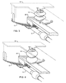
- FIGURE 1 illustrates a preferred embodiment of the composite suspension system 10 of the present invention.
- an axle 12 is illustrated with a mechanical suspension system 14, which in this case is a leaf spring suspension.
- the mechanical suspension system 14 is secured to the axle 12 by any conventional method used today.
- the mechanical suspension system 14 is secured at its ends to a frame/body 16 of a vehicle. In this way, the mechanical suspension system 14 provides support for the frame/body 16 in a conventional manner.
- the composite suspension system 10 also includes a pneumatic suspension system 18, which in this case comprises air springs.
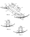
- the air springs 18 may be mounted to the underside of the frame/body 16 as illustrated in FIGS. 1 and 3-6 .
- the air springs 18 may be mounted on an upper surface of a support bracket 20 which is itself mounted on top of the axle 12.
- FIG. 1 illustrates the support bracket 20 mounted so as to clamp onto or around the leaf spring 14.
- the support bracket 20 may be mounted in any manner provided that it is fixed and immovable with respect to the axle 12. An example of such mounting is described in U.S. Patent No. 7,500,688 . It may be undesirable to mount the support bracket 20 directly on the axle 12. In such instance adaptor plates (not shown) may be necessary.
- FIGS. 1 , 5 and 6 illustrate support rings 22 on the support bracket 20.
- the support rings 22 are to receive an end of the air springs 18 when in an inflated position as described further below.
- the support rings 22 may also be mounted on the underside of the frame/body 16 in those instances wherein the air springs 18 are mounted on the support bracket 20 and expand upward towards the frame/body 16 when inflated.
- the support rings 22 are optional features to increase the stability of the air springs 18 with respect to the support bracket 20 or frame/body 16.
- the support rings 22 may be eliminated entirely from either the support bracket 20 or the underside of the frame/body 16 as illustrated in FIGS. 3 and 4 .
- the air springs 18 are movable between inflated and deflated positions.
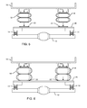
- FIGS. 1 , 3 , 5 and 7 illustrate the air springs 18 in a deflated or stand-by position.
- the air springs 18 When the air springs 18 are deflated they do not support the frame/body 16 relative to the axle 12. In other words, the air springs 18 do not make contact with both the frame/body 16 and the support bracket 20. Thus, when deflated the air springs 18 do not provide support for the body 16, relying solely on the leaf springs 14.
- the air springs 18 When the air springs 18 are inflated they support the frame/body 16 relative to the axle 12.
- the air springs 18 are of sufficient size to make contact with both the frame/body 16 and the support bracket 20 when in an inflated position. In this way, the air springs 18 provide support to the frame/body 16 in addition to that support provided by the leaf springs 14.
- the additional support provided by the air springs 18 is particularly useful where the vehicle is carrying heavy loads which would be too much for a leaf spring suspension 14 on its own.
- FIGURE 2 illustrates a control system regulating the inflation or deflation of the pneumatic suspension system 18.
- An air spring 18 is shown with an air line 24 attached thereto.
- a first hose 26 and second hose 28 are schematically illustrated as being attached to the air line 24.
- the first hose 26 runs from the air line 24 to a compressor 30.
- the compressor 30 provides the air that is used to inflate the air springs 18.
- the compressor 30 is in turn connected to a control panel 32 which may be mounted in a passenger compartment on the vehicle or on an exterior surface of the vehicle.
- the control panel 32 regulates operation of the compressor 30 depending on whether the air springs 18 are to be inflated or deflated.
- a pressure gage 34 is included with the control panel 32 so that a user can regulate the air pressure in the air springs 18.
- the second hose 28 runs from the air line 24 to a valve 36 which is in turn connected to a vacuum or negative pressure source 38.
- the valve 36 is operationally connected to the control panel 32. In this way, the control panel 32 can regulate when the valve 36 is opened and closed.
- the control panel 32 may also be operationally connected to the vacuum source so as to control when the vacuum source 38 is permitted to draw air from the system to deflate the air springs.
- the control panel 32 turns on the compressor 30 which pumps air through the first hose 26 and the air line 24 into the air spring 18. Simultaneously, the control panel closes the valve 36 to block the flow of air from the air line 24 to the second hose 28 which is connected to the vacuum or negative pressure source 38. In this configuration, the compressor 30 pumps air into the air springs 18 until they are inflated to a desired pressure and vehicle body height are achieved, and then the control panel 32 turns off the compressor 30. The air springs 18 are deflated by opening the valve 36, which places the air springs in fluid communication with the vacuum or negative pressure source 38.
- the vacuum or negative pressure source 38 draws air out of the air springs 18 through the open valve 36, second hose 28 and air line 24, to retract the air springs 18 to their minimum height. This allows for maximum clearance when the pneumatic suspension system is in its "stand-by" position.
- the vacuum or negative pressure source 38 may include an existing vacuum source on a vehicle, such as an engine vacuum source. Alternatively, the vacuum source may come from an additional component installed on the vehicle specifically designed to generate negative pressure to draw the air out of the air springs 18.
- the air line 24, first hose 26, second hose 28, air compressor 30, valve 36 and vacuum source 38 comprise a control system 40 for the pneumatic suspension system 18.
- FIGURES 9, 10 and 11 illustrate an alternate embodiment of the composite suspension system 10 of the present invention.
- the difference in this embodiment from the previous preferred embodiment resides in the support bracket 20 and how the same is connected to the axle 12 or mechanical suspension system 14.
- the support bracket 20 does not span across the axle from one mechanical suspension system 14 to the companion mechanical suspension system 14 on the other end of the axle 12.
- Offset brackets 42 allow the support bracket 20 to be mounted in an essentially horizontal position when the mechanical suspension system 14 is oriented at an angle as illustrated in FIGS. 9, 10 and 11 .
- the offset bracket 42 is mounted higher on one side of the support bracket 20 than on the other side.
- the support bracket 20 may include adjustment holes 43 to provide different points of attachment for the offset brackets 42.
- This configuration assures that an essentially horizontal surface is provided on the top of the support bracket 20 for either receiving the air springs 18 when inflated as shown in FIG. 11 or for having the air springs 18 mounted thereupon as illustrated in other figures.
- the essentially horizontal surface assures greater stability and support provided by the pneumatic suspension system 18 when it is in use.
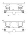
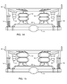
- FIGURES 12-15 illustrate additional alternate embodiments of the composite suspension system 10 of the present invention. The most notable difference is the configuration of the mechanical suspension system 14. In these figures the mechanical suspension system 14 is illustrated as coil springs and/or shock absorbers. Coil springs such as these have been used in prior art suspension systems for quite some time.
- the configuration of the support bracket 20 is essentially the same as in the previous embodiments.
- the pneumatic suspension system or air springs 18 may be mounted on either the underside of the frame/body 16 or the upper side of the support bracket 20. In either case, when the air springs 18 are inflated they make contact with both the frame/body 16 and the support bracket 20 as illustrated in FIGS. 13 and 15 .
- FIGURES 14 and 15 illustrate yet another variation on the composite suspension system 10 of the present invention.
- a rubber pad 44 may be included to provide additional support for the composite suspension system 10. This rubber pad 44 is configured such that the coil springs 14 are not fully compressed by a heavy load being placed on the vehicle frame/body 16 prior to inflation of the air springs 18. The rubber pads 44 may contact the support bracket 20 or another surface under the frame/body 16 when under heavy loading. The rubber pads 44 are not critical to the operation of the composite suspension system 10 and may be omitted.
- FIGURES 16 and 17 illustrate yet another variation on the composite suspension system 10 of the present invention.
- the support bracket 20 comprises two separate support brackets 46. Each separate support bracket 46 is mounted above the axle 12 and configured to separately support each air spring 18 in the pneumatic suspension system 18.
- FIG. 16 illustrates the pneumatic suspension system 18 in a deflated position.
- FIG. 17 illustrates the pneumatic suspension system 18 in an inflated position.
- the pneumatic suspension system 18 may be mounted to the underside of the body 16 and configured to expand downward toward the separate support brackets 46 when inflated.
Description
- This invention relates to suspension systems for vehicles. As used herein, the terms "vehicle" and "vehicles" are intended to include but not be limited to passenger cars, sport utility vehicles, pick-up trucks, commercial trucks, buses, vans, recreational vehicles, motor homes, farm equipment, and non-motorized trailers that carry horses, boats, cars and other loads.
- Since the advent of vehicles, numerous suspension systems have been devised to improve the ride of the vehicle not only for the comfort of the occupants but also for maintaining the structural integrity and aesthetics of the contents by providing sufficient lift capability, vehicle stability, and improved handling. For example, motorized vehicles in use since the early 1900s have used simple leaf spring rear suspension systems as have certain non-motorized vehicles such as trailers. Indeed, a substantial number of modern vehicles including, but not limited to pick-up trucks, vans, sport utility vehicles, commercial trucks, and trailers continue to use simple leaf spring rear suspension systems. Some vehicles also use coil spring suspensions.
- In addition to simple leaf spring or coil spring rear suspension systems, air springs have long been used in various suspension systems in a variety of vehicle types. In known suspension systems employing air springs the air springs are firmly attached to supporting members of the vehicle at the top and bottom portions of the air springs. These systems typically require very high air pressure which causes the air springs, and hence the ride on an air suspension, to be stiff. While systems employing air springs provide additional advantage for carrying or towing heavy loads, the ride is generally stiffer. Thus, air spring suspension systems provide lift when heavily loaded but at the expense of the comfort of the occupants which may not be justified during operation of the vehicle without heavy loads.
- Various aftermarket devices have been developed to provide increased lift capability and stability of a vehicle when carrying heavy loads. Generally, suspension systems strong enough to provide sufficient lift when loaded are always on and make the ride stiffer during unloaded operation. Suspension systems that don't interfere with unloaded operation may not be strong enough to provide sufficient lift when loaded. Additionally, there is often insufficient space in most vehicles for more than one suspension system. While some systems are quite simple and easily added to existing vehicles, others require significant modifications to the standard "original equipment manufacturer" (OEM) product and/or require complicated installation.
- The
US 3,572,749 A shows a vehicle suspension system in which a flexible bladder disposed within a primary suspension coil spring is inflated into axial abutting contact with the sprung and unsprung masses and radial contact with the inner surfaces of the spring coils to provide auxiliary leveling during greater than normal load conditions, and including control means for retracting the bladder axially and radially sufficient to withdraw it from contact with the spring coils and one of the masses when auxiliary leveling is not required. - An air spring/coil spring combination suspension system is disclosed in
US 2006/0175789 A1 . The suspension system for a vehicle having a rear axle and a leaf spring suspension system including a pair of leaf springs mounted over respective ends of the rear axle, comprises a lower support member which is positioned above the rear axle. Furthermore, a plurality of spring assemblies which are mounted above the rear axle, each spring assembly being composed of a coil spring and an air spring arranged around a common central axis, are supported by the lower support member. - The
GB 2 372 795 A - An additional impact stop, especially for the rear suspension of a motor vehicle, is known from
FR 2 554 060 A -
US 5,364,086 A teaches a composite elastomeric air spring and sealing structure. The spring includes a composite elastomeric body having a closed end and an open end. A coil spring is embedded both within the body wall and the closed end, and provides reinforcement of both the body wall and the closed end. The body may be of cylindrical, conical or other shape, depending upon the required function of the spring. The spring may be internally pressurized to provide load leveling or air spring effects. The spring is pneumatically inflated to provide load support and load leveling capability. In the unloaded condition a space is formed between the closed end and a support. - Accordingly, it is an object of the present invention to improve the ride and load-carrying capabilities of existing vehicles with an easy-to-install retrofit suspension system that does not interfere with the factory installed suspension system of the vehicle. The same system can also be integrated into new vehicles to improve ride, handling, and load-carrying capabilities.Another object of the invention is to provide an "on demand" and/or "standby" suspension system that a vehicle operator can engage and disengage as required.
- The present invention fulfills these needs and provides other related advantages.
- The present invention is directed to a composite suspension system for a vehicle, comprising a leaf spring or coil spring suspension system connecting a body of the vehicle to an axle, a support bracket mounted adjacent to the axle, and an air spring suspension system comprising an air spring supported by the body or the support bracket and moveable between inflated and deflated positions, wherein the air spring extends between the upperside of the support bracket and the underside of the body thereby supporting the body relative to the axle when inflated, and when deflated does not support the body relative to the axle and is disengaged from one of the the upperside of the support bracket and the underside of the body, wherein the composite suspension system further comprises a control system for inflating or deflating the air spring suspension system, wherein the control system comprises an air line attached to the air spring, a first hose connecting the air line to an air compressor and a second hose connecting the air line to a vacuum or negative pressure source having a valve therebetween such that the air spring is inflated by activating the air compressor and closing the valve, and deflated by turning off the air compressor and opening the valve to retract the air spring to its minimum height. In other words, the composite suspension system for a vehicle comprises a mechanical suspension system comprising a leaf spring or coil spring suspension system and a pneumatic suspension system comprising an air spring suspension system. The mechanical suspension system connects a body of the vehicle to an axle. The pneumatic suspension system is movable between inflated and deflated positions. In the inflated position, the pneumatic suspension system supports the body of the vehicle relative to the axle. In the deflated position, the pneumatic suspension system does not support the body relative to the axle.
- The mechanical suspension system comprises a leaf spring suspension, a coil spring suspension or a shock absorber. The pneumatic suspension system comprises an air spring suspension that is supported by the body or adjacent to the axle. The composite suspension system further comprises a support bracket mounted adjacent to the axle and preferably a predetermined distance below the body when the body is mounted on the mechanical suspension system. Support rings, bars, or other structure may be included on either the upper side of the support bracket or the underside of the body for receiving the pneumatic suspension system when in the inflated position.
- The composite suspension system further comprises a control system for inflating or deflating the pneumatic suspension system. The control system comprises an air line attached to the pneumatic suspension system, a first hose connecting the air line to an air compressor, and a second hose connecting the air line to a vacuum source having a valve therebetween.
- The composite suspension system may further comprise a control panel for controlling the compressor and valve. The control panel is preferably mounted in a passenger compartment on the vehicle. Using the control system, the pneumatic suspension system is inflated by activating the air compressor until optimum pressure and body height are achieved, and closing the valve. Conversely, the pneumatic suspension system is deflated by opening the valve. A vacuum or negative pressure source, usually provided by a vehicle engine, is introduced to the control system in order to retract the pneumatic suspension system or air springs to their minimum height. This allows for maximum clearance when the pneumatic suspension system is in its "stand-by" position.
- Other features and advantages of the present invention will become apparent from the following more detailed description, taken in conjunction with the accompanying drawings, which illustrate, by way of example, the principles of the invention.
- The accompanying drawings illustrate the invention. In such drawings:
-
FIGURE 1 is an elevated perspective view of a preferred embodiment of the composite suspension system according to the present invention; -
FIGURE 2 is a schematic diagram illustrating the configuration of the control system of an air spring suspension; -
FIGURE 3 is a close-up perspective view of an air spring suspension in a preferred embodiment of the composite suspension system according to the present invention, the air spring suspension being in a deflated position; -
FIGURE 4 is a close-up perspective view of an air spring suspension in a preferred embodiment of the composite suspension system according to the present invention, the air spring suspension being in an inflated position; -
FIGURE 5 is a rear view of an air spring suspension in a preferred embodiment of the composite suspension system according to the present invention, the air spring suspension being in a deflated position; -
FIGURE 6 is a rear view of an air spring suspension in a preferred embodiment of the composite suspension system according to the present invention, the air spring suspension being in an inflated position; -
FIGURE 7 is a rear view of an alternative embodiment of the composite suspension system according to the present invention, the air spring suspension being in a deflated position; -
FIGURE 8 is a rear view of an alternate embodiment of the composite suspension system according to the present invention, the air spring suspension being in an inflated position; -
FIGURE 9 is an elevated perspective view of another alternate embodiment of the composite suspension system according to the present invention; -
FIGURE 10 is a side view of another alternate embodiment of the composite suspension system according to the present invention, the air spring suspension being in a deflated position; -
FIGURE 11 is a side view of another alternate embodiment of the composite suspension system according to the present invention, the air spring suspension being in an inflated position; -
FIGURE 12 is a rear view illustrating yet another alternate embodiment of the composite suspension system according to the present invention, the air spring suspension being in a deflated position; -
FIGURE 13 is a rear view of yet another alternate embodiment of the composite suspension system according to the present invention, the air spring suspension being in an inflated position; -
FIGURE 14 is a rear view illustrating yet another alternate embodiment of the composite suspension system according to the present invention, the air spring suspension being in a deflated position; -
FIGURE 15 is a rear view of yet another alternate embodiment of the composite suspension system according to the present invention, the air spring suspension being in an inflated position; -
FIGURE 16 is a rear view illustrating yet another alternate embodiment of the composite suspension system according to the present invention, the air spring suspension being in a deflated position; and -
FIGURE 17 is a rear view of yet another alternate embodiment of the composite suspension system according to the present invention, the air spring suspension being in an inflated position. - The present invention is directed to a composite suspension system for a vehicle that provides improved ride and load carrying capabilities over existing suspension systems. More particularly, as generally illustrated in
FIGS. 1-17 , the present invention is directed to a composite suspension system comprising a mechanical suspension system and a pneumatic suspension system, wherein the pneumatic suspension system may be selectively engaged or disengaged. -
FIGURE 1 illustrates a preferred embodiment of thecomposite suspension system 10 of the present invention. In this embodiment anaxle 12 is illustrated with amechanical suspension system 14, which in this case is a leaf spring suspension. Themechanical suspension system 14 is secured to theaxle 12 by any conventional method used today. Themechanical suspension system 14 is secured at its ends to a frame/body 16 of a vehicle. In this way, themechanical suspension system 14 provides support for the frame/body 16 in a conventional manner. - The
composite suspension system 10 also includes apneumatic suspension system 18, which in this case comprises air springs. The air springs 18 may be mounted to the underside of the frame/body 16 as illustrated inFIGS. 1 and3-6 . Alternatively, the air springs 18 may be mounted on an upper surface of asupport bracket 20 which is itself mounted on top of theaxle 12.FIG. 1 illustrates thesupport bracket 20 mounted so as to clamp onto or around theleaf spring 14. Thesupport bracket 20 may be mounted in any manner provided that it is fixed and immovable with respect to theaxle 12. An example of such mounting is described inU.S. Patent No. 7,500,688 . It may be undesirable to mount thesupport bracket 20 directly on theaxle 12. In such instance adaptor plates (not shown) may be necessary. In addition, it may be necessary to modify the shape of thesupport bracket 20, i.e., include an offset, so that thesupport bracket 20 accommodates existing structures on the vehicle, such as the universal joint on theaxle 12. Such modifications are within the ordinary skill of the art. -
FIGS. 1 ,5 and 6 illustrate support rings 22 on thesupport bracket 20. The support rings 22 are to receive an end of the air springs 18 when in an inflated position as described further below. The support rings 22 may also be mounted on the underside of the frame/body 16 in those instances wherein the air springs 18 are mounted on thesupport bracket 20 and expand upward towards the frame/body 16 when inflated. The support rings 22 are optional features to increase the stability of the air springs 18 with respect to thesupport bracket 20 or frame/body 16. The support rings 22 may be eliminated entirely from either thesupport bracket 20 or the underside of the frame/body 16 as illustrated inFIGS. 3 and 4 . - The air springs 18 are movable between inflated and deflated positions.
FIGS. 1 ,3 ,5 and7 illustrate the air springs 18 in a deflated or stand-by position. When the air springs 18 are deflated they do not support the frame/body 16 relative to theaxle 12. In other words, the air springs 18 do not make contact with both the frame/body 16 and thesupport bracket 20. Thus, when deflated the air springs 18 do not provide support for thebody 16, relying solely on the leaf springs 14. - When the air springs 18 are inflated they support the frame/
body 16 relative to theaxle 12. The air springs 18 are of sufficient size to make contact with both the frame/body 16 and thesupport bracket 20 when in an inflated position. In this way, the air springs 18 provide support to the frame/body 16 in addition to that support provided by the leaf springs 14. The additional support provided by the air springs 18 is particularly useful where the vehicle is carrying heavy loads which would be too much for aleaf spring suspension 14 on its own. -
FIGURE 2 illustrates a control system regulating the inflation or deflation of thepneumatic suspension system 18. Anair spring 18 is shown with anair line 24 attached thereto. Afirst hose 26 andsecond hose 28 are schematically illustrated as being attached to theair line 24. Thefirst hose 26 runs from theair line 24 to acompressor 30. Thecompressor 30 provides the air that is used to inflate the air springs 18. Thecompressor 30 is in turn connected to acontrol panel 32 which may be mounted in a passenger compartment on the vehicle or on an exterior surface of the vehicle. Thecontrol panel 32 regulates operation of thecompressor 30 depending on whether the air springs 18 are to be inflated or deflated. Apressure gage 34 is included with thecontrol panel 32 so that a user can regulate the air pressure in the air springs 18. - The
second hose 28 runs from theair line 24 to avalve 36 which is in turn connected to a vacuum ornegative pressure source 38. Thevalve 36 is operationally connected to thecontrol panel 32. In this way, thecontrol panel 32 can regulate when thevalve 36 is opened and closed. Thecontrol panel 32 may also be operationally connected to the vacuum source so as to control when thevacuum source 38 is permitted to draw air from the system to deflate the air springs. - To inflate the air springs 18 the
control panel 32 turns on thecompressor 30 which pumps air through thefirst hose 26 and theair line 24 into theair spring 18. Simultaneously, the control panel closes thevalve 36 to block the flow of air from theair line 24 to thesecond hose 28 which is connected to the vacuum ornegative pressure source 38. In this configuration, thecompressor 30 pumps air into the air springs 18 until they are inflated to a desired pressure and vehicle body height are achieved, and then thecontrol panel 32 turns off thecompressor 30. The air springs 18 are deflated by opening thevalve 36, which places the air springs in fluid communication with the vacuum ornegative pressure source 38. The vacuum ornegative pressure source 38 draws air out of the air springs 18 through theopen valve 36,second hose 28 andair line 24, to retract the air springs 18 to their minimum height. This allows for maximum clearance when the pneumatic suspension system is in its "stand-by" position. The vacuum ornegative pressure source 38 may include an existing vacuum source on a vehicle, such as an engine vacuum source. Alternatively, the vacuum source may come from an additional component installed on the vehicle specifically designed to generate negative pressure to draw the air out of the air springs 18. Theair line 24,first hose 26,second hose 28,air compressor 30,valve 36 andvacuum source 38 comprise acontrol system 40 for thepneumatic suspension system 18. -
FIGURES 9, 10 and 11 illustrate an alternate embodiment of thecomposite suspension system 10 of the present invention. The difference in this embodiment from the previous preferred embodiment resides in thesupport bracket 20 and how the same is connected to theaxle 12 ormechanical suspension system 14. In this embodiment, thesupport bracket 20 does not span across the axle from onemechanical suspension system 14 to the companionmechanical suspension system 14 on the other end of theaxle 12. Offsetbrackets 42 allow thesupport bracket 20 to be mounted in an essentially horizontal position when themechanical suspension system 14 is oriented at an angle as illustrated inFIGS. 9, 10 and 11 . As seen in these figures, the offsetbracket 42 is mounted higher on one side of thesupport bracket 20 than on the other side. Thesupport bracket 20 may include adjustment holes 43 to provide different points of attachment for the offsetbrackets 42. This configuration assures that an essentially horizontal surface is provided on the top of thesupport bracket 20 for either receiving the air springs 18 when inflated as shown inFIG. 11 or for having the air springs 18 mounted thereupon as illustrated in other figures. The essentially horizontal surface assures greater stability and support provided by thepneumatic suspension system 18 when it is in use. -
FIGURES 12-15 illustrate additional alternate embodiments of thecomposite suspension system 10 of the present invention. The most notable difference is the configuration of themechanical suspension system 14. In these figures themechanical suspension system 14 is illustrated as coil springs and/or shock absorbers. Coil springs such as these have been used in prior art suspension systems for quite some time. - Another difference resides in the configuration of the
support bracket 20. Considering how the coil springs 14 are attached to theaxle 12 it is necessary to attach thesupport bracket 20 to theaxle 12 at a point closer to the center of the axle than was permitted with the use of leaf springs. Otherwise, the configuration of thesupport bracket 20 is essentially the same as in the previous embodiments. As seen inFIGS. 12 and14 , the pneumatic suspension system or air springs 18 may be mounted on either the underside of the frame/body 16 or the upper side of thesupport bracket 20. In either case, when the air springs 18 are inflated they make contact with both the frame/body 16 and thesupport bracket 20 as illustrated inFIGS. 13 and15 . -
FIGURES 14 and 15 illustrate yet another variation on thecomposite suspension system 10 of the present invention. Arubber pad 44 may be included to provide additional support for thecomposite suspension system 10. Thisrubber pad 44 is configured such that the coil springs 14 are not fully compressed by a heavy load being placed on the vehicle frame/body 16 prior to inflation of the air springs 18. Therubber pads 44 may contact thesupport bracket 20 or another surface under the frame/body 16 when under heavy loading. Therubber pads 44 are not critical to the operation of thecomposite suspension system 10 and may be omitted. -
FIGURES 16 and 17 illustrate yet another variation on thecomposite suspension system 10 of the present invention. In this embodiment, thesupport bracket 20 comprises twoseparate support brackets 46. Eachseparate support bracket 46 is mounted above theaxle 12 and configured to separately support eachair spring 18 in thepneumatic suspension system 18.FIG. 16 illustrates thepneumatic suspension system 18 in a deflated position.FIG. 17 illustrates thepneumatic suspension system 18 in an inflated position. Although not illustrated, thepneumatic suspension system 18 may be mounted to the underside of thebody 16 and configured to expand downward toward theseparate support brackets 46 when inflated. - Although several embodiments have been described in detail for purposes of illustration, various modifications may be made without departing from the scope and spirit of the invention. Accordingly, the invention is not to be limited, except as by the appended claims.
Claims (6)
- A composite suspension system (10) for a vehicle, comprising: a leaf spring or coil spring suspension system connecting a body (16) of the vehicle to an axle (12); a support bracket (20, 46) mounted adjacent to the axle (12); and an air spring suspension system comprising an air spring (18) supported by the body (16) or the support bracket (20, 46) and moveable between inflated and deflated positions, wherein the air spring (18) extends between the upperside of the support bracket (20, 46) and the underside of the body (16) thereby supporting the body (16) relative to the axle (12) when inflated, and when deflated does not support the body (16) relative to the axle (12) and is disengaged from one of the the upperside of the support bracket (20, 46) and the underside of the body (16); wherein the composite suspension system (10) further comprises a control system (40) for inflating or deflating the air spring suspension system, wherein the control system (40) comprises an air line (24) attached to the air spring (18), a first hose (26) connecting the air line (24) to an air compressor (30) and a second hose (28) connecting the air line (24) to a vacuum or negative pressure source (38) having a valve (36) therebetween such that the air spring (18) is inflated by activating the air compressor (30) and closing the valve (36), and deflated by turning off the air compressor (30) and opening the valve (36) to retract the air spring (18) to its minimum height.
- The composite suspension system (10) of claim 1, wherein the support bracket (20, 46) is mounted a pre-determined distance below the body (16) when the body (16) is mounted on the leaf spring or coil spring suspension system.
- The composite suspension system (10) of claim 1 or 2, wherein the composite suspension system (10) further comprises a shock absorber.
- The composite suspension system (10) of any one of the preceding claims, further comprising support rings (22) on either the upperside of the support bracket (20, 46) or the underside of the body (16) for receiving the air spring suspension system when inflated.
- The composite suspension system (10) of any one of the preceding claims, further comprising a control panel (32) for controlling the compressor (30) and valve (36).
- The composite suspension system (10) of any one of the preceding claims, wherein the vacuum or negative pressure source (38) comprises a vehicle engine vacuum source.
Applications Claiming Priority (5)
| Application Number | Priority Date | Filing Date | Title |
|---|---|---|---|
| US7037508P | 2008-03-20 | 2008-03-20 | |
| US14325409P | 2009-01-08 | 2009-01-08 | |
| US15086709P | 2009-02-09 | 2009-02-09 | |
| US15309109P | 2009-02-17 | 2009-02-17 | |
| PCT/US2009/037728 WO2009117617A2 (en) | 2008-03-20 | 2009-03-19 | Composite suspension system for a vehicle |
Publications (3)
| Publication Number | Publication Date |
|---|---|
| EP2254761A2 EP2254761A2 (en) | 2010-12-01 |
| EP2254761A4 EP2254761A4 (en) | 2012-02-01 |
| EP2254761B1 true EP2254761B1 (en) | 2015-05-06 |
Family
ID=41091546
Family Applications (1)
| Application Number | Title | Priority Date | Filing Date |
|---|---|---|---|
| EP20090721519 Not-in-force EP2254761B1 (en) | 2008-03-20 | 2009-03-19 | Composite suspension system for a vehicle |
Country Status (8)
| Country | Link |
|---|---|
| US (1) | US7681898B2 (en) |
| EP (1) | EP2254761B1 (en) |
| JP (1) | JP2011516322A (en) |
| KR (1) | KR20110021732A (en) |
| CN (1) | CN102036841A (en) |
| BR (1) | BRPI0910230A2 (en) |
| CA (1) | CA2718985A1 (en) |
| WO (1) | WO2009117617A2 (en) |
Families Citing this family (11)
| Publication number | Priority date | Publication date | Assignee | Title |
|---|---|---|---|---|
| US20120025027A1 (en) * | 2010-07-01 | 2012-02-02 | Conax Florida Corporation | System for Air Borne Deployment of Palletized Cargo |
| CN102101423B (en) * | 2011-01-31 | 2013-04-17 | 徐州徐工随车起重机有限公司 | Suspending device for bridge detection working vehicle |
| FR2990508A1 (en) * | 2012-05-10 | 2013-11-15 | Peugeot Citroen Automobiles Sa | Load measuring device for car, has height sensor determining elevation of case between two inflation states of cushion, where cushion includes spring to retract cushion by evacuating air contained in cushion after measurement of load of car |
| MX2014002930A (en) * | 2013-03-13 | 2015-04-29 | Hendrickson Usa Llc | Air suspension control system. |
| US9315084B2 (en) * | 2013-12-18 | 2016-04-19 | Agco Corporation | Adjustable limit bar with sway control |
| CN104773045B (en) * | 2015-04-27 | 2017-11-14 | 席玉林 | Cluster spring compensates suspension arrangement |
| GB201601298D0 (en) * | 2016-01-25 | 2016-03-09 | Agco Int Gmbh | An axle suspension system for a tractor |
| DE102016222310A1 (en) | 2016-11-14 | 2018-05-17 | Contitech Luftfedersysteme Gmbh | Method for operating a pneumatic actuator and actuator |
| CN111645472B (en) * | 2019-08-27 | 2021-06-18 | 山东神骏车辆制造有限公司 | Control method of truck suspension variable stiffness auxiliary device |
| US11655030B2 (en) | 2020-06-29 | 2023-05-23 | Hdt Expeditionary Systems, Inc. | Inflatable impact attenuator for parachuted items |
| CN113335255B (en) * | 2021-07-07 | 2022-12-27 | 四川丰科汽车部件有限公司 | Shock attenuation formula air receiver for heavy truck |
Family Cites Families (80)
| Publication number | Priority date | Publication date | Assignee | Title |
|---|---|---|---|---|
| US1502209A (en) * | 1922-05-25 | 1924-07-22 | Walter S Peterson | Shock absorber |
| US1961634A (en) | 1930-05-05 | 1934-06-05 | Reingold B | Shock absorber |
| US2042596A (en) * | 1932-06-11 | 1936-06-02 | Gouirand Rene | Pneumatic suspension |
| US2023135A (en) | 1933-02-11 | 1935-12-03 | Charles A Hawkins | Vehicle suspension |
| US2030263A (en) | 1933-12-13 | 1936-02-11 | Jr George Anderson Mercer | Yielding support for vehicles |
| US2145891A (en) | 1936-01-28 | 1939-02-07 | Jr John V Rice | Antishock spring |
| US2441629A (en) | 1946-03-07 | 1948-05-18 | Forrest E Hahn | Shock absorber |
| DE1633708U (en) | 1948-11-12 | 1952-01-24 | Fritz Dipl Ing Nallinger | AIR SUSPENSION FOR VEHICLES. |
| US2711315A (en) | 1952-02-26 | 1955-06-21 | Carl H Mosebach | Spring suspension and shock absorbing devices for automobiles |
| US2933104A (en) * | 1955-07-05 | 1960-04-19 | Gen Motors Corp | Control mechanism |
| FR1155573A (en) | 1955-08-01 | 1958-05-06 | Daimler Benz Ag | Elastic balancing suspension for vehicles, in particular for motor vehicles with separate suspension from the wheels |
| US2807475A (en) * | 1955-08-02 | 1957-09-24 | David D Post | Vehicle suspension and stabilizing system |
| US2902275A (en) * | 1956-07-10 | 1959-09-01 | Rockwell Standard Co | Air spring |
| GB912618A (en) | 1957-03-09 | |||
| DE1173352B (en) * | 1957-03-30 | 1964-07-02 | Daimler Benz Ag | Wheel suspension for vehicles, in particular motor vehicles |
| US2969990A (en) * | 1958-01-15 | 1961-01-31 | Ford Motor Co | Closed air suspension system for motor vehicle |
| FR1216104A (en) * | 1958-02-26 | 1960-04-22 | Daimler Benz Ag | Automotive car with air elastic suspension |
| US3001783A (en) * | 1958-10-06 | 1961-09-26 | Universal Air Lift Inc | Spring suspension devices for motor vehicles |
| US3063732A (en) * | 1958-12-01 | 1962-11-13 | Western Unit Corp | Vehicle-suspension means employing leaf and air spring assemblies in combination |
| US2971772A (en) * | 1959-03-18 | 1961-02-14 | Fruehauf Trailer Co | Wheel suspension and cantilever spring bracing therefor for trailer |
| FR1241767A (en) * | 1959-07-29 | 1960-09-23 | Renault | Device for automatic closing of circuits in a pneumatic or oleopneumatic vehicle suspension |
| US3031179A (en) * | 1959-08-17 | 1962-04-24 | Thomas H Peirce | Suspension system |
| US3031204A (en) * | 1959-11-19 | 1962-04-24 | Gen Motors Corp | Vehicle suspension with load simulating leveling device |
| US3118659A (en) * | 1960-02-09 | 1964-01-21 | Luxembourg Brev Participations | Compression springs made of an elastomer |
| US3033554A (en) * | 1960-09-26 | 1962-05-08 | Gen Motors Corp | Vacuum spring with disabling control |
| US3116918A (en) * | 1960-10-14 | 1964-01-07 | Gen Motors Corp | Vacuum spring control apparatus |
| US3178167A (en) | 1961-12-30 | 1965-04-13 | Bosch Gmbh Robert | Suspension for vehicles or the like |
| US3257122A (en) * | 1962-12-10 | 1966-06-21 | Palmer Fultz | Stabilizing device |
| US3287025A (en) | 1963-07-18 | 1966-11-22 | Alfa Romeo Spa | Suspension with constant trim and frequency |
| US3276476A (en) * | 1963-11-29 | 1966-10-04 | Gen Motors Corp | Fluid control valve |
| US3237957A (en) * | 1965-01-04 | 1966-03-01 | Western Unit Corp | Carriage with compound spring suspension assembly |
| US3342141A (en) * | 1965-05-03 | 1967-09-19 | Chesapeake & Ohio Railway | Convertible rail-highway vehicle truck |
| US3361087A (en) * | 1966-02-01 | 1968-01-02 | Budd Co | Spring apparatus for railway cars |
| US3390895A (en) * | 1966-03-25 | 1968-07-02 | Sam C. Verdi | Auxiliary axle suspension |
| US3480293A (en) * | 1966-09-15 | 1969-11-25 | Arthur E Vogel | Control system for vehicle suspensions |
| US3448975A (en) * | 1966-10-21 | 1969-06-10 | Dura Corp | Vehicle wheel suspension |
| US3572749A (en) | 1968-11-29 | 1971-03-30 | Gen Motors Corp | Vehicle suspension with retractable auxiliary overload spring |
| US3572676A (en) | 1968-12-23 | 1971-03-30 | Gen Motors Corp | Fluid spring incorporating fluid medium conserving flow control means |
| DE1901795A1 (en) | 1969-01-15 | 1970-08-13 | Langen & Co | Suspension device for vehicles with automatic load balancing |
| US3552767A (en) | 1969-05-01 | 1971-01-05 | Gen Motors Corp | Vehicle suspension having a dual mode composite spring |
| DE1940399A1 (en) * | 1969-08-08 | 1971-02-18 | Ernst Wackenhut | Suspension for double-axle vehicles |
| US3599954A (en) * | 1969-10-08 | 1971-08-17 | Gen Motors Corp | Compound vacuum spring |
| US3632130A (en) | 1970-06-25 | 1972-01-04 | Abex Corp | Vehicle suspensions |
| US3664681A (en) * | 1970-12-04 | 1972-05-23 | Ride Rite Corp | Air spring mounting for pickup trucks |
| US3727899A (en) | 1971-04-07 | 1973-04-17 | Air Lift Co | Spring suspension unit particularly for vehicle suspension systems |
| US3690689A (en) | 1971-04-21 | 1972-09-12 | Gen Motors Corp | Combination valve for controlling two pressure sources |
| US3751066A (en) * | 1971-09-01 | 1973-08-07 | Sycon Corp | Wheel suspension system |
| US3754768A (en) | 1972-04-19 | 1973-08-28 | Gen Motors Corp | Height control valve for vehicle leveling |
| US3810650A (en) | 1972-05-03 | 1974-05-14 | N Hudson | Anti-dive banking suspension apparatus for vehicles |
| US3768820A (en) * | 1972-06-15 | 1973-10-30 | Gen Motors Corp | Vehicle leveling control with vacuum regulator valve means |
| US3784221A (en) * | 1972-07-24 | 1974-01-08 | V Frasier | Air ride suspension for trucks |
| US3884454A (en) * | 1973-10-29 | 1975-05-20 | Lear Siegler Inc | Air spring system and damped air valve therefor |
| US3850445A (en) * | 1974-02-11 | 1974-11-26 | Lear Siegler Inc | Combined air spring and leaf spring suspension |
| US3966223A (en) | 1974-11-08 | 1976-06-29 | Carr James P | Vehicle suspension |
| US4099741A (en) * | 1976-12-06 | 1978-07-11 | American Carrier Equipment, Inc. | Supplemental air spring assembly |
| FR2554060B3 (en) | 1983-10-28 | 1986-03-14 | Renault | ADDITIONAL SELF-INFLATABLE SHOCK STOP, PARTICULARLY FOR MOTOR VEHICLE SUSPENSION |
| JPS60157514U (en) * | 1984-03-30 | 1985-10-19 | 日野自動車株式会社 | Air suspension car drive system |
| US4580809A (en) * | 1984-05-09 | 1986-04-08 | Vehicle Systems, Inc. | Vehicle suspension system |
| JPS619319A (en) * | 1984-06-26 | 1986-01-16 | Mazda Motor Corp | Vehicle height regulating device for vehicle |
| US4783089A (en) * | 1984-10-15 | 1988-11-08 | C & K Venture Income I-Coast | Air spring control system and method |
| US4687224A (en) | 1985-06-14 | 1987-08-18 | Navistar International Corporation | Dual offset cantilevered spring suspension |
| US4736931A (en) | 1986-10-03 | 1988-04-12 | Christopherson Rollin F | Dampening shock absorber |
| JPH02502990A (en) | 1988-01-20 | 1990-09-20 | ムーグ インコーポレーテツド | Vehicle suspension system and how it works |
| US4830395A (en) | 1988-02-22 | 1989-05-16 | Foley Jimmy D | Stabilizer system for racing cars |
| US5058917A (en) * | 1990-10-01 | 1991-10-22 | Neway Corp. | Two-stage retractable suspension |
| JPH06507227A (en) * | 1991-04-29 | 1994-08-11 | パトン,エイチ.ネイル | Composite elastomer springs and mounting devices |
| WO1993019959A1 (en) * | 1992-04-07 | 1993-10-14 | Driverite Limited | Improvements in and relating to auxiliary suspension systems |
| DE4231641C2 (en) | 1992-09-22 | 1996-12-12 | Daimler Benz Ag | Suspension strut for automotive suspension systems |
| US5346246A (en) | 1992-11-23 | 1994-09-13 | Load-Air, Inc. | Automatic air bag suspension control system |
| JPH1148732A (en) * | 1997-08-08 | 1999-02-23 | Hino Motors Ltd | Mounting structure of leaf spring for air suspension |
| US6840525B1 (en) * | 2000-03-14 | 2005-01-11 | Meritor Heavy Vehicle Systems Limited | Air spring and pedestal |
| GB2372795A (en) * | 2001-02-28 | 2002-09-04 | Gibbs Int Tech Ltd | Internally reinforced air springs |
| JP4158150B2 (en) * | 2003-06-04 | 2008-10-01 | いすゞ自動車株式会社 | Vehicle height adjustment device |
| US6935625B2 (en) * | 2003-08-18 | 2005-08-30 | Haldex Brake Corporation | Air suspension system with air shut off valve |
| US20050236792A1 (en) * | 2003-11-20 | 2005-10-27 | Hedenberg William E | Stabilizing air suspension system |
| US7959174B2 (en) | 2004-11-18 | 2011-06-14 | Tlc Suspensions, Llc | Air spring/coil spring combination suspension system |
| US7500688B2 (en) * | 2005-02-08 | 2009-03-10 | Tlc Suspensions, Llc | Air spring/coil spring combination suspension system |
| CN2837127Y (en) * | 2005-04-26 | 2006-11-15 | 东风汽车悬架弹簧有限公司 | A rear composite air suspension frame assembly for coach chassis |
| CN2855798Y (en) * | 2005-12-19 | 2007-01-10 | 北京柯布克科技开发有限公司 | Hyperbolic, air-sac type two air-spring composite air suspension for driving bridge |
| JP2007204001A (en) * | 2006-02-06 | 2007-08-16 | Bridgestone Corp | Suspension device |
-
2009
- 2009-03-19 US US12/407,723 patent/US7681898B2/en not_active Expired - Fee Related
- 2009-03-19 JP JP2011500967A patent/JP2011516322A/en active Pending
- 2009-03-19 EP EP20090721519 patent/EP2254761B1/en not_active Not-in-force
- 2009-03-19 WO PCT/US2009/037728 patent/WO2009117617A2/en active Application Filing
- 2009-03-19 CA CA2718985A patent/CA2718985A1/en not_active Abandoned
- 2009-03-19 KR KR1020107023302A patent/KR20110021732A/en not_active Application Discontinuation
- 2009-03-19 BR BRPI0910230A patent/BRPI0910230A2/en not_active IP Right Cessation
- 2009-03-19 CN CN2009801183172A patent/CN102036841A/en active Pending
Also Published As
| Publication number | Publication date |
|---|---|
| BRPI0910230A2 (en) | 2015-09-29 |
| CN102036841A (en) | 2011-04-27 |
| EP2254761A2 (en) | 2010-12-01 |
| EP2254761A4 (en) | 2012-02-01 |
| US7681898B2 (en) | 2010-03-23 |
| CA2718985A1 (en) | 2009-09-24 |
| KR20110021732A (en) | 2011-03-04 |
| WO2009117617A2 (en) | 2009-09-24 |
| US20090179398A1 (en) | 2009-07-16 |
| WO2009117617A3 (en) | 2009-12-30 |
| JP2011516322A (en) | 2011-05-26 |
Similar Documents
| Publication | Publication Date | Title |
|---|---|---|
| EP2254761B1 (en) | Composite suspension system for a vehicle | |
| US20170241504A1 (en) | Damping air spring with dynamically variable orifice | |
| US7938416B2 (en) | Air suspension adapter kit | |
| US10569814B2 (en) | Lift axle auxiliary suspension systems | |
| US2257913A (en) | Suspension system and method | |
| EP1456044B1 (en) | Air spring control system for a vehicle's lift axle | |
| US20200361550A1 (en) | Lift axle drag reduction system and method | |
| US4174855A (en) | Wheeled vehicle axle suspension system | |
| EP0918955A1 (en) | Beam-type axle suspension system | |
| AU2018230966B2 (en) | Damping convoluted air spring | |
| WO2012071337A2 (en) | Side-beam lift assembly for heavy-duty vehicles | |
| US20060103102A1 (en) | Air spring/coil spring combination suspension system | |
| US7934734B2 (en) | Suspension air spring lift kit | |
| US20190337349A1 (en) | Pneumatic control system for vehicles and other loaded structures | |
| US20050023792A1 (en) | Lateral leaf spring with inboard air spring trailer suspension | |
| US11813911B2 (en) | Suspension mount for an automotive vehicle | |
| US3038716A (en) | Automobile suspension | |
| US20240116320A1 (en) | Under beam lift assembly for heavy-duty vehicles | |
| KR100353132B1 (en) | A passive wheel lifting apparatus for truck and method thereof | |
| CA2630294C (en) | Air suspension adapter kit | |
| KR200209487Y1 (en) | A passive wheel lifting apparatus for truck |
Legal Events
| Date | Code | Title | Description |
|---|---|---|---|
| PUAI | Public reference made under article 153(3) epc to a published international application that has entered the european phase |
Free format text: ORIGINAL CODE: 0009012 |
|
| 17P | Request for examination filed |
Effective date: 20100923 |
|
| AK | Designated contracting states |
Kind code of ref document: A2 Designated state(s): AT BE BG CH CY CZ DE DK EE ES FI FR GB GR HR HU IE IS IT LI LT LU LV MC MK MT NL NO PL PT RO SE SI SK TR |
|
| AX | Request for extension of the european patent |
Extension state: AL BA RS |
|
| DAX | Request for extension of the european patent (deleted) | ||
| A4 | Supplementary search report drawn up and despatched |
Effective date: 20120104 |
|
| RIC1 | Information provided on ipc code assigned before grant |
Ipc: B60G 11/46 20060101AFI20111229BHEP Ipc: B60G 11/56 20060101ALI20111229BHEP |
|
| 17Q | First examination report despatched |
Effective date: 20121217 |
|
| GRAP | Despatch of communication of intention to grant a patent |
Free format text: ORIGINAL CODE: EPIDOSNIGR1 |
|
| INTG | Intention to grant announced |
Effective date: 20141126 |
|
| GRAS | Grant fee paid |
Free format text: ORIGINAL CODE: EPIDOSNIGR3 |
|
| GRAA | (expected) grant |
Free format text: ORIGINAL CODE: 0009210 |
|
| AK | Designated contracting states |
Kind code of ref document: B1 Designated state(s): AT BE BG CH CY CZ DE DK EE ES FI FR GB GR HR HU IE IS IT LI LT LU LV MC MK MT NL NO PL PT RO SE SI SK TR |
|
| REG | Reference to a national code |
Ref country code: GB Ref legal event code: FG4D |
|
| REG | Reference to a national code |
Ref country code: CH Ref legal event code: EP |
|
| REG | Reference to a national code |
Ref country code: IE Ref legal event code: FG4D |
|
| REG | Reference to a national code |
Ref country code: AT Ref legal event code: REF Ref document number: 725433 Country of ref document: AT Kind code of ref document: T Effective date: 20150615 |
|
| REG | Reference to a national code |
Ref country code: DE Ref legal event code: R096 Ref document number: 602009031089 Country of ref document: DE Effective date: 20150618 |
|
| REG | Reference to a national code |
Ref country code: AT Ref legal event code: MK05 Ref document number: 725433 Country of ref document: AT Kind code of ref document: T Effective date: 20150506 Ref country code: SE Ref legal event code: TRGR |
|
| REG | Reference to a national code |
Ref country code: NL Ref legal event code: MP Effective date: 20150506 |
|
| REG | Reference to a national code |
Ref country code: LT Ref legal event code: MG4D |
|
| PG25 | Lapsed in a contracting state [announced via postgrant information from national office to epo] |
Ref country code: HR Free format text: LAPSE BECAUSE OF FAILURE TO SUBMIT A TRANSLATION OF THE DESCRIPTION OR TO PAY THE FEE WITHIN THE PRESCRIBED TIME-LIMIT Effective date: 20150506 Ref country code: PT Free format text: LAPSE BECAUSE OF FAILURE TO SUBMIT A TRANSLATION OF THE DESCRIPTION OR TO PAY THE FEE WITHIN THE PRESCRIBED TIME-LIMIT Effective date: 20150907 Ref country code: NO Free format text: LAPSE BECAUSE OF FAILURE TO SUBMIT A TRANSLATION OF THE DESCRIPTION OR TO PAY THE FEE WITHIN THE PRESCRIBED TIME-LIMIT Effective date: 20150806 Ref country code: ES Free format text: LAPSE BECAUSE OF FAILURE TO SUBMIT A TRANSLATION OF THE DESCRIPTION OR TO PAY THE FEE WITHIN THE PRESCRIBED TIME-LIMIT Effective date: 20150506 Ref country code: LT Free format text: LAPSE BECAUSE OF FAILURE TO SUBMIT A TRANSLATION OF THE DESCRIPTION OR TO PAY THE FEE WITHIN THE PRESCRIBED TIME-LIMIT Effective date: 20150506 Ref country code: FI Free format text: LAPSE BECAUSE OF FAILURE TO SUBMIT A TRANSLATION OF THE DESCRIPTION OR TO PAY THE FEE WITHIN THE PRESCRIBED TIME-LIMIT Effective date: 20150506 |
|
| PG25 | Lapsed in a contracting state [announced via postgrant information from national office to epo] |
Ref country code: LV Free format text: LAPSE BECAUSE OF FAILURE TO SUBMIT A TRANSLATION OF THE DESCRIPTION OR TO PAY THE FEE WITHIN THE PRESCRIBED TIME-LIMIT Effective date: 20150506 Ref country code: AT Free format text: LAPSE BECAUSE OF FAILURE TO SUBMIT A TRANSLATION OF THE DESCRIPTION OR TO PAY THE FEE WITHIN THE PRESCRIBED TIME-LIMIT Effective date: 20150506 Ref country code: BG Free format text: LAPSE BECAUSE OF FAILURE TO SUBMIT A TRANSLATION OF THE DESCRIPTION OR TO PAY THE FEE WITHIN THE PRESCRIBED TIME-LIMIT Effective date: 20150806 Ref country code: IS Free format text: LAPSE BECAUSE OF FAILURE TO SUBMIT A TRANSLATION OF THE DESCRIPTION OR TO PAY THE FEE WITHIN THE PRESCRIBED TIME-LIMIT Effective date: 20150906 Ref country code: GR Free format text: LAPSE BECAUSE OF FAILURE TO SUBMIT A TRANSLATION OF THE DESCRIPTION OR TO PAY THE FEE WITHIN THE PRESCRIBED TIME-LIMIT Effective date: 20150807 |
|
| PG25 | Lapsed in a contracting state [announced via postgrant information from national office to epo] |
Ref country code: DK Free format text: LAPSE BECAUSE OF FAILURE TO SUBMIT A TRANSLATION OF THE DESCRIPTION OR TO PAY THE FEE WITHIN THE PRESCRIBED TIME-LIMIT Effective date: 20150506 Ref country code: EE Free format text: LAPSE BECAUSE OF FAILURE TO SUBMIT A TRANSLATION OF THE DESCRIPTION OR TO PAY THE FEE WITHIN THE PRESCRIBED TIME-LIMIT Effective date: 20150506 |
|
| REG | Reference to a national code |
Ref country code: DE Ref legal event code: R097 Ref document number: 602009031089 Country of ref document: DE |
|
| PG25 | Lapsed in a contracting state [announced via postgrant information from national office to epo] |
Ref country code: PL Free format text: LAPSE BECAUSE OF FAILURE TO SUBMIT A TRANSLATION OF THE DESCRIPTION OR TO PAY THE FEE WITHIN THE PRESCRIBED TIME-LIMIT Effective date: 20150506 Ref country code: RO Free format text: LAPSE BECAUSE OF NON-PAYMENT OF DUE FEES Effective date: 20150506 Ref country code: SK Free format text: LAPSE BECAUSE OF FAILURE TO SUBMIT A TRANSLATION OF THE DESCRIPTION OR TO PAY THE FEE WITHIN THE PRESCRIBED TIME-LIMIT Effective date: 20150506 Ref country code: CZ Free format text: LAPSE BECAUSE OF FAILURE TO SUBMIT A TRANSLATION OF THE DESCRIPTION OR TO PAY THE FEE WITHIN THE PRESCRIBED TIME-LIMIT Effective date: 20150506 |
|
| PLBE | No opposition filed within time limit |
Free format text: ORIGINAL CODE: 0009261 |
|
| STAA | Information on the status of an ep patent application or granted ep patent |
Free format text: STATUS: NO OPPOSITION FILED WITHIN TIME LIMIT |
|
| 26N | No opposition filed |
Effective date: 20160209 |
|
| PG25 | Lapsed in a contracting state [announced via postgrant information from national office to epo] |
Ref country code: IT Free format text: LAPSE BECAUSE OF FAILURE TO SUBMIT A TRANSLATION OF THE DESCRIPTION OR TO PAY THE FEE WITHIN THE PRESCRIBED TIME-LIMIT Effective date: 20150506 |
|
| PG25 | Lapsed in a contracting state [announced via postgrant information from national office to epo] |
Ref country code: SI Free format text: LAPSE BECAUSE OF FAILURE TO SUBMIT A TRANSLATION OF THE DESCRIPTION OR TO PAY THE FEE WITHIN THE PRESCRIBED TIME-LIMIT Effective date: 20150506 |
|
| PG25 | Lapsed in a contracting state [announced via postgrant information from national office to epo] |
Ref country code: BE Free format text: LAPSE BECAUSE OF FAILURE TO SUBMIT A TRANSLATION OF THE DESCRIPTION OR TO PAY THE FEE WITHIN THE PRESCRIBED TIME-LIMIT Effective date: 20150506 |
|
| REG | Reference to a national code |
Ref country code: DE Ref legal event code: R119 Ref document number: 602009031089 Country of ref document: DE |
|
| PG25 | Lapsed in a contracting state [announced via postgrant information from national office to epo] |
Ref country code: MC Free format text: LAPSE BECAUSE OF FAILURE TO SUBMIT A TRANSLATION OF THE DESCRIPTION OR TO PAY THE FEE WITHIN THE PRESCRIBED TIME-LIMIT Effective date: 20150506 Ref country code: LU Free format text: LAPSE BECAUSE OF FAILURE TO SUBMIT A TRANSLATION OF THE DESCRIPTION OR TO PAY THE FEE WITHIN THE PRESCRIBED TIME-LIMIT Effective date: 20160319 |
|
| REG | Reference to a national code |
Ref country code: CH Ref legal event code: PL |
|
| REG | Reference to a national code |
Ref country code: SE Ref legal event code: EUG |
|
| GBPC | Gb: european patent ceased through non-payment of renewal fee |
Effective date: 20160319 |
|
| PG25 | Lapsed in a contracting state [announced via postgrant information from national office to epo] |
Ref country code: SE Free format text: LAPSE BECAUSE OF NON-PAYMENT OF DUE FEES Effective date: 20160320 |
|
| REG | Reference to a national code |
Ref country code: IE Ref legal event code: MM4A |
|
| REG | Reference to a national code |
Ref country code: FR Ref legal event code: ST Effective date: 20161130 |
|
| PG25 | Lapsed in a contracting state [announced via postgrant information from national office to epo] |
Ref country code: CH Free format text: LAPSE BECAUSE OF NON-PAYMENT OF DUE FEES Effective date: 20160331 Ref country code: FR Free format text: LAPSE BECAUSE OF NON-PAYMENT OF DUE FEES Effective date: 20160331 Ref country code: IE Free format text: LAPSE BECAUSE OF NON-PAYMENT OF DUE FEES Effective date: 20160319 Ref country code: DE Free format text: LAPSE BECAUSE OF NON-PAYMENT OF DUE FEES Effective date: 20161001 Ref country code: LI Free format text: LAPSE BECAUSE OF NON-PAYMENT OF DUE FEES Effective date: 20160331 Ref country code: GB Free format text: LAPSE BECAUSE OF NON-PAYMENT OF DUE FEES Effective date: 20160319 |
|
| PG25 | Lapsed in a contracting state [announced via postgrant information from national office to epo] |
Ref country code: NL Free format text: LAPSE BECAUSE OF FAILURE TO SUBMIT A TRANSLATION OF THE DESCRIPTION OR TO PAY THE FEE WITHIN THE PRESCRIBED TIME-LIMIT Effective date: 20150506 |
|
| PG25 | Lapsed in a contracting state [announced via postgrant information from national office to epo] |
Ref country code: MT Free format text: LAPSE BECAUSE OF FAILURE TO SUBMIT A TRANSLATION OF THE DESCRIPTION OR TO PAY THE FEE WITHIN THE PRESCRIBED TIME-LIMIT Effective date: 20150506 |
|
| PG25 | Lapsed in a contracting state [announced via postgrant information from national office to epo] |
Ref country code: CY Free format text: LAPSE BECAUSE OF FAILURE TO SUBMIT A TRANSLATION OF THE DESCRIPTION OR TO PAY THE FEE WITHIN THE PRESCRIBED TIME-LIMIT Effective date: 20150506 Ref country code: HU Free format text: LAPSE BECAUSE OF FAILURE TO SUBMIT A TRANSLATION OF THE DESCRIPTION OR TO PAY THE FEE WITHIN THE PRESCRIBED TIME-LIMIT; INVALID AB INITIO Effective date: 20090319 |
|
| PG25 | Lapsed in a contracting state [announced via postgrant information from national office to epo] |
Ref country code: MK Free format text: LAPSE BECAUSE OF FAILURE TO SUBMIT A TRANSLATION OF THE DESCRIPTION OR TO PAY THE FEE WITHIN THE PRESCRIBED TIME-LIMIT Effective date: 20150506 Ref country code: TR Free format text: LAPSE BECAUSE OF FAILURE TO SUBMIT A TRANSLATION OF THE DESCRIPTION OR TO PAY THE FEE WITHIN THE PRESCRIBED TIME-LIMIT Effective date: 20150506 Ref country code: MT Free format text: LAPSE BECAUSE OF FAILURE TO SUBMIT A TRANSLATION OF THE DESCRIPTION OR TO PAY THE FEE WITHIN THE PRESCRIBED TIME-LIMIT Effective date: 20160331 |