EP2254221A2 - Cooling system for rotating machine - Google Patents
Cooling system for rotating machine Download PDFInfo
- Publication number
- EP2254221A2 EP2254221A2 EP10156556A EP10156556A EP2254221A2 EP 2254221 A2 EP2254221 A2 EP 2254221A2 EP 10156556 A EP10156556 A EP 10156556A EP 10156556 A EP10156556 A EP 10156556A EP 2254221 A2 EP2254221 A2 EP 2254221A2
- Authority
- EP
- European Patent Office
- Prior art keywords
- annular space
- shaft
- rotor
- electrical machine
- stationary
- Prior art date
- Legal status (The legal status is an assumption and is not a legal conclusion. Google has not performed a legal analysis and makes no representation as to the accuracy of the status listed.)
- Granted
Links
- 238000001816 cooling Methods 0.000 title claims description 28
- 239000012530 fluid Substances 0.000 claims abstract description 25
- 239000002826 coolant Substances 0.000 claims description 27
- 238000003475 lamination Methods 0.000 claims description 4
- 230000037361 pathway Effects 0.000 claims description 4
- 238000012546 transfer Methods 0.000 description 8
- 239000000110 cooling liquid Substances 0.000 description 7
- 241000237503 Pectinidae Species 0.000 description 5
- 239000007788 liquid Substances 0.000 description 5
- 235000020637 scallop Nutrition 0.000 description 5
- 238000013461 design Methods 0.000 description 4
- 238000000034 method Methods 0.000 description 4
- 238000000926 separation method Methods 0.000 description 3
- 230000008859 change Effects 0.000 description 2
- 238000012986 modification Methods 0.000 description 2
- 230000004048 modification Effects 0.000 description 2
- 238000004804 winding Methods 0.000 description 2
- 229910000831 Steel Inorganic materials 0.000 description 1
- 238000013459 approach Methods 0.000 description 1
- 230000000712 assembly Effects 0.000 description 1
- 238000000429 assembly Methods 0.000 description 1
- 230000004323 axial length Effects 0.000 description 1
- 230000004888 barrier function Effects 0.000 description 1
- 239000000428 dust Substances 0.000 description 1
- 239000012772 electrical insulation material Substances 0.000 description 1
- AEDZKIACDBYJLQ-UHFFFAOYSA-N ethane-1,2-diol;hydrate Chemical compound O.OCCO AEDZKIACDBYJLQ-UHFFFAOYSA-N 0.000 description 1
- 230000004907 flux Effects 0.000 description 1
- 239000000463 material Substances 0.000 description 1
- ALDITMKAAPLVJK-UHFFFAOYSA-N prop-1-ene;hydrate Chemical group O.CC=C ALDITMKAAPLVJK-UHFFFAOYSA-N 0.000 description 1
- DNIAPMSPPWPWGF-UHFFFAOYSA-N propylene glycol Substances CC(O)CO DNIAPMSPPWPWGF-UHFFFAOYSA-N 0.000 description 1
- 239000010959 steel Substances 0.000 description 1
- XLYOFNOQVPJJNP-UHFFFAOYSA-N water Substances O XLYOFNOQVPJJNP-UHFFFAOYSA-N 0.000 description 1
Images


Classifications
-
- H—ELECTRICITY
- H02—GENERATION; CONVERSION OR DISTRIBUTION OF ELECTRIC POWER
- H02K—DYNAMO-ELECTRIC MACHINES
- H02K1/00—Details of the magnetic circuit
- H02K1/06—Details of the magnetic circuit characterised by the shape, form or construction
- H02K1/22—Rotating parts of the magnetic circuit
- H02K1/32—Rotating parts of the magnetic circuit with channels or ducts for flow of cooling medium
-
- H—ELECTRICITY
- H02—GENERATION; CONVERSION OR DISTRIBUTION OF ELECTRIC POWER
- H02K—DYNAMO-ELECTRIC MACHINES
- H02K9/00—Arrangements for cooling or ventilating
- H02K9/19—Arrangements for cooling or ventilating for machines with closed casing and closed-circuit cooling using a liquid cooling medium, e.g. oil
- H02K9/193—Arrangements for cooling or ventilating for machines with closed casing and closed-circuit cooling using a liquid cooling medium, e.g. oil with provision for replenishing the cooling medium; with means for preventing leakage of the cooling medium
-
- H—ELECTRICITY
- H02—GENERATION; CONVERSION OR DISTRIBUTION OF ELECTRIC POWER
- H02K—DYNAMO-ELECTRIC MACHINES
- H02K9/00—Arrangements for cooling or ventilating
- H02K9/19—Arrangements for cooling or ventilating for machines with closed casing and closed-circuit cooling using a liquid cooling medium, e.g. oil
- H02K9/197—Arrangements for cooling or ventilating for machines with closed casing and closed-circuit cooling using a liquid cooling medium, e.g. oil in which the rotor or stator space is fluid-tight, e.g. to provide for different cooling media for rotor and stator
-
- H—ELECTRICITY
- H02—GENERATION; CONVERSION OR DISTRIBUTION OF ELECTRIC POWER
- H02K—DYNAMO-ELECTRIC MACHINES
- H02K1/00—Details of the magnetic circuit
- H02K1/06—Details of the magnetic circuit characterised by the shape, form or construction
- H02K1/22—Rotating parts of the magnetic circuit
- H02K1/27—Rotor cores with permanent magnets
- H02K1/2706—Inner rotors
- H02K1/272—Inner rotors the magnetisation axis of the magnets being perpendicular to the rotor axis
- H02K1/274—Inner rotors the magnetisation axis of the magnets being perpendicular to the rotor axis the rotor consisting of two or more circumferentially positioned magnets
- H02K1/2753—Inner rotors the magnetisation axis of the magnets being perpendicular to the rotor axis the rotor consisting of two or more circumferentially positioned magnets the rotor consisting of magnets or groups of magnets arranged with alternating polarity
- H02K1/276—Magnets embedded in the magnetic core, e.g. interior permanent magnets [IPM]
- H02K1/2766—Magnets embedded in the magnetic core, e.g. interior permanent magnets [IPM] having a flux concentration effect
- H02K1/2773—Magnets embedded in the magnetic core, e.g. interior permanent magnets [IPM] having a flux concentration effect consisting of tangentially magnetized radial magnets
Definitions
- the subject matter disclosed herein relates generally to cooling of rotating machines, and more particularly, to rotor cooling.
- Electric motors can generate considerable heat, making motor cooling difficult, especially in high power output motors with size and weight constraints. Additionally, in order to avoid excessive wear due to differential thermal expansion, it is important to cool the inner motor components (e.g., rotor) as well as the outer motor components (e.g., casing, stator). Motor cooling can be a challenge for motors that are subjected to a wide range of ambient temperatures, humidity levels, and dust/dirt levels.
- the size of the rotor and stator are selected so that heat transfer may occur through use of a gas in the air-gap between the rotor and stator.
- a common disadvantage in this example is increased mass and volume of the machine.
- Another method of cooling is to flood the rotor cavity with a dielectric fluid such as oil.
- a dielectric fluid such as oil.
- the oil is flung around the machine, resulting in a high heat transfer coefficient along the surfaces of the rotor in contact with the oil. Heat is thus transferred from the rotor to the oil, and then removed from the oil via natural convection, forced convection, or liquid cooling.
- speed increases churning losses in the fluid become high and limit the usefulness of this technique.
- an electrical machine comprises a rotor disposed on a rotatable shaft and defining a plurality of radial protrusions extending from the shaft up to a periphery of the rotor.
- the radial protrusions have cavities.
- a stationary shaft is disposed concentrically within the rotatable shaft wherein an annular space is formed between the stationary and rotatable shaft.
- Magnetic segments are disposed on the radial protrusions, and a fluid path extends from within the stationary shaft into the annular space and through the cavities within the radial protrusions.
- an electrical machine comprises a stator having stator coils interposed between stator laminations.
- a rotor is disposed on a rotatable shaft that defines a plurality of radial protrusions extending from the shaft towards a periphery of the rotor.
- Each of the protrusions has at least one cavity extending therethrough.
- a stationary shaft having a hollow region is disposed concentrically within the rotatable shaft, wherein an annular space is formed between the stationary and rotatable shafts.
- a fluid path extends from the hollow region, into the annular space, and through the cavities of the radial protrusions.
- Magnetic segments are disposed on the radial protrusions, and a seal is disposed between the stationary shaft and the rotatable shaft enclosing the annular space and provides a pathway to an exit.
- a rotor cooling system in another embodiment, includes an annular space defined between a rotatable shaft and a hollow stationary shaft. A fluid path is defined from within the hollow stationary shaft and into the annular space.
- the cooling system includes plurality of radial cavities extending from the annular space towards a periphery of radial protrusions and plurality of axial holes on the radial protrusions.
- Power output of rotating electrical machines such as motors and generators may be increased by increasing the machine diameter and/or length.
- the machine mass increases proportionately with no significant change in power density.
- power and power density increase as the rotating speed increases.
- the amount of increase in mass is limited by the maximum speed limit of the machine.
- Another technique to increase power density of rotating machines is to increase the stator current loading and thus the air gap magnetic flux density.
- this technique requires additional cooling elements that result in added machine mass.
- Embodiments disclosed herein provide enhanced cooling of rotating machines without requiring such additional mass.
- FIG. 1 is a cross-sectional view of an electrical machine implementing a rotor cooling system according to an aspect of the invention.
- the electrical machine 10 includes a stator 12 having stator windings 14 disposed adjacent to a rotor core 16 fixed on a rotatable shaft 18.
- the rotatable shaft 18 is rotatably coupled to a stator frame 20 via bearings 22, 24.
- Stator 12 having stator windings 14 and a stator core is disposed within the stator frame 20, and an air gap (not shown) is formed between the rotor 16 and the stator 12)
- a stationary shaft 28 is disposed concentrically within the rotatable shaft 18 to form an annular space 30 between stationary shaft 28 and rotatable shaft 18.
- a seal 32 is disposed between the rotatable shaft 18 and the stationary shaft 28 enclosing the annular space 30 and further coupled to an exit 34.
- Working of sub assemblies of the electrical machine 10 are discussed in detail below.
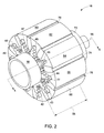
- FIG. 2 illustrates a perspective view of a rotor implemented in the electrical machine of FIG. 1 .
- the rotor 16 includes multiple radial protrusions illustrated by numerals 42-49 extending from the rotatable shaft 18 up to a periphery 56 of the rotor 16.
- Radial protrusions extend along the axial length 58 of the rotor.
- a plurality of magnetic segments, 60, 62, 64, 66, 68 are provided with each being disposed on a respective one of the protrusions.
- the magnetic segments comprise steel laminations.
- Multiple permanent magnets, for example 70, 72, 74, 76 are provided with each being interposed between a respective pair of the magnetic segments.
- Each radial protrusion includes multiple cavities having axial and radial holes such as shown by elements 77 and 78 to provide a fluid path.
- FIG. 3 is a cross-sectional axial view of an embodiment of the rotor wherein the magnetic segments are not shown for convenience of illustrating the structure of radial protrusions.
- the stationary shaft 28 is disposed concentrically within the rotatable shaft 18 forming the annular space 30, and, in the embodiment of FIG. 3 , each protrusion 42-51 respectively has cavities 80-100 extending from the annular space 30 toward the periphery of the protrusions.
- the magnetic segments are disposed on the protrusions, for example on 42 that occupies at least partially the space 102, 104 available between two protrusions. Furthermore, the space 102, 104 accommodates permanent magnets between the magnetic segments as illustrated in FIG. 2 .
- a cooling liquid or a coolant may be circulated from within the hollow stationary shaft 105 and into the annular space 30.
- the coolant comprises water.
- Other non-limiting coolant examples include water-propylene glycol, water-ethylene glycol, oil, and Fluorinerts.
- FIG. 4 is a perspective view of the rotor according to an embodiment of the invention.
- Each protrusion may optionally include multiple fins.
- protrusion 45 includes fins 106, 108.
- the cavity 100 extends from the rotatable shaft 18 radially up towards the periphery 110 and further axially along length of the rotor.
- the fins 106 and 108 may include similar such cavities extending axially to facilitate flow of coolant. Coolant that flows within the cavities help removes heat from the magnetic segments ( FIG. 2 ) that are positioned on the protrusions.
- FIG. 5 illustrates a detailed view of an exemplary cooling liquid path through the annular space and the cavities during an operation of the electrical machine. Further, FIG. 5 is a zoomed in view of a portion of the electrical machine of FIG. 1 . In an exemplary embodiment, the zoomed in view 112 depicts rotatable shaft 18 rests on bearing 24.
- the coolant flows within the hollow stationary shaft through a pathway represented by arrows 124, 126, and 128. At the far end 150, the coolant branches radially outward into paths 130 and 132. Coolant flows towards the exit via path 134-138 (and 140-144) and exits the rotating frame via the exit respectively through paths 146 and 148. Furthermore, the cooling liquid also flows through the cavities in the protrusions 152, 154, 156, and 158 to remove heat from core of the magnetic segments as discussed with respect to FIG. 4 .
- FIG. 6 further illustrates an example of flow of coolant through the cavities and the annular space.
- a portion of the branched coolant flow 130 passes through the cavity 152 (referenced by numeral 151) that extends up towards the periphery, then passes through cavity 100 which runs axially (referenced by numeral 153), and then flows back to the annular space via cavity 154 (referenced by numeral 155).
- fins 106, 108 may include respective cavities 160, 162 having coolant flowing through and reaching the annular space via 154.
- the cavity and flow arrangement for one protrusion 45 is discussed. However, similar arrangements may exist on some or each of the other protrusion 42-51.
- protrusion 50 is shown as including cavities 156, 161, 158 coupled to the annular space 30.
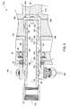
- FIG. 7 illustrates a detailed view of an exemplary seal to be used in the electrical machine of FIG. 1 .
- the seal facilitates the coolant to traverse between rotating (shaft 18) and stationary frames as the coolant exits through exit 34.
- the fluid exits the annular space 30 and enters the exit 34 as illustrated by the flow path 166.
- the exit plenum (not shown) is attached to exit 34 and coupled to external components such as pump and heat exchanger (not shown.) Most of the coolant exits through the outlet (146, 148 as referenced in FIG. 5 .)
- a small gap 172 is provided between rotatable shaft 18 and the stator frame 20 such that the coolant may flow into this gap.
- the rubbing seal 170 is located in this opening area that seals the coolant between the rotatable shaft 18 and the seal ring 174.
- the seal ring may be bolted to a stator end plate 176.
- the rubbing seal 170 operates by forming a physical barrier between the rotating (shaft 18) and stationary surfaces (stator frame 20). Such rubbing seals are designed to withstand the friction that occurs with the rotatable shaft 18.
- a drainage groove 168 between the seal ring 174 and the bearing 24 may be provided, and an axial flow passage (not shown) may be used to link the drainage groove 168 to a collection for drained coolant outside the machine.
- FIG. 8 illustrates a cross-sectional view of the rotor liquid cooling system implementing baffles in the annular space according to an embodiment of the invention.
- At least one or more baffles 180-188 are disposed around the stationary shaft 28.
- Such baffle rings help in controlling a flow resistance in the two parallel paths 190, 192.
- the flow to each path 190, 192 may be adjusted by changing the dimensions of baffles. Accordingly, the design requirement of flow resistance determines the number of baffles.
- baffle ring affects the heat transfer in the rotor cooling system 181.
- baffle ring may be placed in an appropriate location in the annular space 30 for effective heat transfer.
- a baffle ring may be placed near 196, thus causing more flow resistance for path 190.
- the baffle ring 188 will cause more fluid to go through path 200.
- Additional baffles, such as 186, 184, 182, and 180 can be added for additional flow resistance.
- the baffles may be used to increase the flow disturbance and in turn increase heat transfer on surfaces adjacent and downstream of the baffles. By this way, coolant can be directed into the most heated positions using the baffles to execute an efficient heat transfer.
- FIGs. 9 and 10 illustrate exemplary embodiments of various baffle ring structures for use in the annular space of rotor of FIG. 8 .
- the baffle ring may include an even surface as illustrated in 206.
- the baffle ring may include scallops at the inside diameter (210), or series of arcs (208), or may have a combination of arcs and scallops (not shown). As illustrated herein, four arcs/scallops are used. However, the number of arcs or scallops may vary based on the desired flow resistance. The diameter of the baffle and the depth of the scallops may also be varied accordingly.
- a side profile view of the baffle ring is illustrated by the reference numeral 212.
- FIG. 10 illustrates various embodiments of the edges used in baffle ring of FIG. 9 .
- Different embodiments 214-222 are possible choice of edges that may be implemented on the baffle ring of FIG. 9 .
- the shape may affect the flow separation downstream of the baffles. For example, when place near 194 (referenced in FIG. 8 ), and desired not to affect the flow near 194, shape of the edges may be hydro-dynamically designed to reduce flow separation. In another example, for greater flow separation a reverse ramp design (216) may be designed.
- such rotor cooling design enables designing high power density rotating electric machines that generate losses within their rotor structure.
- internal temperature is maintained within electrical insulation material limits and other material thermal limits within the rotor.
- Presently contemplated embodiments of the invention remove losses via heat transfer, allowing the rotor to remain below rated temperatures.
- the effectiveness of the heat removal directly impacts the machine power density.
- a more effective cooling scheme will allow the machine to be smaller, and enabling high power density machine design.
Landscapes
- Engineering & Computer Science (AREA)
- Power Engineering (AREA)
- Motor Or Generator Cooling System (AREA)
- Iron Core Of Rotating Electric Machines (AREA)
Abstract
Description
- The subject matter disclosed herein relates generally to cooling of rotating machines, and more particularly, to rotor cooling.
- Electric motors can generate considerable heat, making motor cooling difficult, especially in high power output motors with size and weight constraints. Additionally, in order to avoid excessive wear due to differential thermal expansion, it is important to cool the inner motor components (e.g., rotor) as well as the outer motor components (e.g., casing, stator). Motor cooling can be a challenge for motors that are subjected to a wide range of ambient temperatures, humidity levels, and dust/dirt levels.
- A number of different approaches have been implemented to cool electric motors. In one example, the size of the rotor and stator are selected so that heat transfer may occur through use of a gas in the air-gap between the rotor and stator. However, a common disadvantage in this example is increased mass and volume of the machine.
- Another method of cooling is to flood the rotor cavity with a dielectric fluid such as oil. As the rotor speed increases, the oil is flung around the machine, resulting in a high heat transfer coefficient along the surfaces of the rotor in contact with the oil. Heat is thus transferred from the rotor to the oil, and then removed from the oil via natural convection, forced convection, or liquid cooling. However, as speed increases, churning losses in the fluid become high and limit the usefulness of this technique.
- There is a need to provide an improved rotor assembly cooling system.
- Briefly, in one embodiment, an electrical machine comprises a rotor disposed on a rotatable shaft and defining a plurality of radial protrusions extending from the shaft up to a periphery of the rotor. The radial protrusions have cavities. A stationary shaft is disposed concentrically within the rotatable shaft wherein an annular space is formed between the stationary and rotatable shaft. Magnetic segments are disposed on the radial protrusions, and a fluid path extends from within the stationary shaft into the annular space and through the cavities within the radial protrusions.
- In another embodiment, an electrical machine comprises a stator having stator coils interposed between stator laminations. A rotor is disposed on a rotatable shaft that defines a plurality of radial protrusions extending from the shaft towards a periphery of the rotor. Each of the protrusions has at least one cavity extending therethrough. A stationary shaft having a hollow region is disposed concentrically within the rotatable shaft, wherein an annular space is formed between the stationary and rotatable shafts. A fluid path extends from the hollow region, into the annular space, and through the cavities of the radial protrusions. Magnetic segments are disposed on the radial protrusions, and a seal is disposed between the stationary shaft and the rotatable shaft enclosing the annular space and provides a pathway to an exit.
- In another embodiment, a rotor cooling system is provided. The rotor cooling system includes an annular space defined between a rotatable shaft and a hollow stationary shaft. A fluid path is defined from within the hollow stationary shaft and into the annular space. The cooling system includes plurality of radial cavities extending from the annular space towards a periphery of radial protrusions and plurality of axial holes on the radial protrusions.
- These and other features, aspects, and advantages of the present invention will become better understood when the following detailed description is read with reference to the accompanying drawings in which like characters represent like parts throughout the drawings, wherein:
-
FIG. 1 illustrates cross-sectional view of an electrical machine implementing a rotor cooling system according to an aspect of the invention; -
FIG. 2 illustrates a perspective view of a rotor implemented in the electrical machine ofFIG. 1 ; -
FIG. 3 is a cross-sectional axial view of the rotor implemented according to an aspect of the invention; -
FIG. 4 is a perspective view of the rotor according to an embodiment of the invention; -
FIG. 5 illustrates a detailed view of cooling liquid path through the annular space and the cavities during an operation of the electrical machine; -
FIG. 6 illustrates flow of cooling liquid through the cavities and the annular space according to an embodiment of the invention; -
FIG. 7 illustrates a detailed view of the seal implemented in the electrical machine ofFIG. 5 ; -
FIG. 8 illustrates a cross-sectional view of the rotor liquid cooling system implementing baffles in the annular space according to an embodiment of the invention; and -
FIGs. 9 and 10 illustrates exemplary embodiments of the baffle ring structure implemented in the annular space of rotor ofFIG. 8 . - Power output of rotating electrical machines such as motors and generators may be increased by increasing the machine diameter and/or length. However, when increasing the machine size, the machine mass increases proportionately with no significant change in power density. For a given rotating machine mass, power and power density increase as the rotating speed increases. Further, the amount of increase in mass is limited by the maximum speed limit of the machine. Another technique to increase power density of rotating machines is to increase the stator current loading and thus the air gap magnetic flux density. However, this technique requires additional cooling elements that result in added machine mass. Embodiments disclosed herein provide enhanced cooling of rotating machines without requiring such additional mass.
-
FIG. 1 is a cross-sectional view of an electrical machine implementing a rotor cooling system according to an aspect of the invention. Theelectrical machine 10 includes astator 12 havingstator windings 14 disposed adjacent to arotor core 16 fixed on arotatable shaft 18. Therotatable shaft 18 is rotatably coupled to astator frame 20 viabearings Stator 12 havingstator windings 14 and a stator core is disposed within thestator frame 20, and an air gap (not shown) is formed between therotor 16 and the stator 12) Astationary shaft 28 is disposed concentrically within therotatable shaft 18 to form anannular space 30 betweenstationary shaft 28 androtatable shaft 18. Aseal 32 is disposed between therotatable shaft 18 and thestationary shaft 28 enclosing theannular space 30 and further coupled to anexit 34. Working of sub assemblies of theelectrical machine 10 are discussed in detail below. -
FIG. 2 illustrates a perspective view of a rotor implemented in the electrical machine ofFIG. 1 . Therotor 16 includes multiple radial protrusions illustrated by numerals 42-49 extending from therotatable shaft 18 up to aperiphery 56 of therotor 16. Radial protrusions extend along theaxial length 58 of the rotor. A plurality of magnetic segments, 60, 62, 64, 66, 68 are provided with each being disposed on a respective one of the protrusions. In one example, the magnetic segments comprise steel laminations. Multiple permanent magnets, for example 70, 72, 74, 76 are provided with each being interposed between a respective pair of the magnetic segments. Each radial protrusion includes multiple cavities having axial and radial holes such as shown byelements 77 and 78 to provide a fluid path. -
FIG. 3 is a cross-sectional axial view of an embodiment of the rotor wherein the magnetic segments are not shown for convenience of illustrating the structure of radial protrusions. - The
stationary shaft 28 is disposed concentrically within therotatable shaft 18 forming theannular space 30, and, in the embodiment ofFIG. 3 , each protrusion 42-51 respectively has cavities 80-100 extending from theannular space 30 toward the periphery of the protrusions. The magnetic segments are disposed on the protrusions, for example on 42 that occupies at least partially thespace space FIG. 2 . A cooling liquid or a coolant may be circulated from within the hollowstationary shaft 105 and into theannular space 30. In one example, the coolant comprises water. Other non-limiting coolant examples include water-propylene glycol, water-ethylene glycol, oil, and Fluorinerts. -
FIG. 4 is a perspective view of the rotor according to an embodiment of the invention. - Each protrusion may optionally include multiple fins. In the illustrated embodiment, for
example protrusion 45 includesfins cavity 100 extends from therotatable shaft 18 radially up towards theperiphery 110 and further axially along length of the rotor. Thefins FIG. 2 ) that are positioned on the protrusions. -
FIG. 5 illustrates a detailed view of an exemplary cooling liquid path through the annular space and the cavities during an operation of the electrical machine. Further,FIG. 5 is a zoomed in view of a portion of the electrical machine ofFIG. 1 . In an exemplary embodiment, the zoomed inview 112 depictsrotatable shaft 18 rests on bearing 24. -
Stationary shaft 28 is disposed concentrically within therotatable shaft 18 defining theannular space 30. Thestationary shaft 28 is disposed towards afar end 150 of the rotatable shaft such that theannular space 30 is defined in the end region (114) as well as the side regions (116, 118). Coolant may be fed through a pump (not shown) radially inward (122) into the hollowstationary shaft 28 at anopening 121 of the stationary shaft. - The coolant flows within the hollow stationary shaft through a pathway represented by
arrows far end 150, the coolant branches radially outward intopaths paths protrusions FIG. 4 . -
FIG. 6 further illustrates an example of flow of coolant through the cavities and the annular space. In the illustrated embodiment, a portion of the branchedcoolant flow 130 passes through the cavity 152 (referenced by numeral 151) that extends up towards the periphery, then passes throughcavity 100 which runs axially (referenced by numeral 153), and then flows back to the annular space via cavity 154 (referenced by numeral 155). Similarly,fins respective cavities 160, 162 having coolant flowing through and reaching the annular space via 154. As described herein, the cavity and flow arrangement for oneprotrusion 45 is discussed. However, similar arrangements may exist on some or each of the other protrusion 42-51. For example,protrusion 50 is shown as includingcavities annular space 30. - The coolant removes some of the heat generated in the rotor due to electrical losses. The
annular space 30 establishes balance between flow resistance and the liquid flow rate and thus enhances the heat transfer capability at the rotating surface. In an exemplary embodiment, the annular space is in the range of about 0.1 to 0.3 inches and is designed for electrical machine rating of about 30kW to about 50 kW. For example, an input temperature of the cooling liquid of about 105°C is designed to absorb heat from the rotor in theannular space 30 and the cavities that extend into core of the rotor. The output temperature of the cooling liquid at the exit may be about 115°C which indicates a fluid temperature rise of about 10°C. The heated liquid may be pumped to heat exchangers if desired, and, once cooled, may be pumped back into the machine. -
FIG. 7 illustrates a detailed view of an exemplary seal to be used in the electrical machine ofFIG. 1 . The seal facilitates the coolant to traverse between rotating (shaft 18) and stationary frames as the coolant exits throughexit 34. In one embodiment, the fluid exits theannular space 30 and enters theexit 34 as illustrated by theflow path 166. The exit plenum (not shown) is attached to exit 34 and coupled to external components such as pump and heat exchanger (not shown.) Most of the coolant exits through the outlet (146, 148 as referenced inFIG. 5 .) Asmall gap 172 is provided betweenrotatable shaft 18 and thestator frame 20 such that the coolant may flow into this gap. At the end of the gap is a larger opening formed between aseal ring 174 and therotatable shaft 18. The rubbingseal 170 is located in this opening area that seals the coolant between therotatable shaft 18 and theseal ring 174. The seal ring may be bolted to astator end plate 176. The rubbingseal 170 operates by forming a physical barrier between the rotating (shaft 18) and stationary surfaces (stator frame 20). Such rubbing seals are designed to withstand the friction that occurs with therotatable shaft 18. Adrainage groove 168 between theseal ring 174 and thebearing 24 may be provided, and an axial flow passage (not shown) may be used to link thedrainage groove 168 to a collection for drained coolant outside the machine. -
FIG. 8 illustrates a cross-sectional view of the rotor liquid cooling system implementing baffles in the annular space according to an embodiment of the invention. At least one or more baffles 180-188 are disposed around thestationary shaft 28. Such baffle rings help in controlling a flow resistance in the twoparallel paths path - In an exemplary operation, the location of the baffle ring affects the heat transfer in the
rotor cooling system 181. Accordingly, baffle ring may be placed in an appropriate location in theannular space 30 for effective heat transfer. For example, for more flow throughpath 200, a baffle ring may be placed near 196, thus causing more flow resistance forpath 190. Thebaffle ring 188 will cause more fluid to go throughpath 200. Additional baffles, such as 186, 184, 182, and 180 can be added for additional flow resistance. In addition to flow resistance, the baffles may be used to increase the flow disturbance and in turn increase heat transfer on surfaces adjacent and downstream of the baffles. By this way, coolant can be directed into the most heated positions using the baffles to execute an efficient heat transfer. -
FIGs. 9 and 10 illustrate exemplary embodiments of various baffle ring structures for use in the annular space of rotor ofFIG. 8 . The baffle ring may include an even surface as illustrated in 206. In one embodiment, the baffle ring may include scallops at the inside diameter (210), or series of arcs (208), or may have a combination of arcs and scallops (not shown). As illustrated herein, four arcs/scallops are used. However, the number of arcs or scallops may vary based on the desired flow resistance. The diameter of the baffle and the depth of the scallops may also be varied accordingly. A side profile view of the baffle ring is illustrated by thereference numeral 212. -
FIG. 10 illustrates various embodiments of the edges used in baffle ring ofFIG. 9 . Different embodiments 214-222 are possible choice of edges that may be implemented on the baffle ring ofFIG. 9 . The shape may affect the flow separation downstream of the baffles. For example, when place near 194 (referenced inFIG. 8 ), and desired not to affect the flow near 194, shape of the edges may be hydro-dynamically designed to reduce flow separation. In another example, for greater flow separation a reverse ramp design (216) may be designed. - Advantageously, such rotor cooling design enables designing high power density rotating electric machines that generate losses within their rotor structure. By effective heat removal, internal temperature is maintained within electrical insulation material limits and other material thermal limits within the rotor. Presently contemplated embodiments of the invention remove losses via heat transfer, allowing the rotor to remain below rated temperatures. The effectiveness of the heat removal directly impacts the machine power density. Thus a more effective cooling scheme will allow the machine to be smaller, and enabling high power density machine design.
- While only certain features of the invention have been illustrated and described herein, many modifications and changes will occur to those skilled in the art. It is, therefore, to be understood that the appended claims are intended to cover all such modifications and changes as fall within the true spirit of the invention.
- Aspects of the present invention are defined in the following numbered clauses:
- 1. An electrical machine comprising:
- a rotor disposed on a rotatable shaft and defining a plurality of radial protrusions extending from the shaft towards a periphery of the rotor, each of the protrusions having at least one cavity extending therethrough;
- a stationary shaft disposed concentrically within the rotatable shaft and including an interior hollow region, wherein an annular space is formed between the stationary and rotatable shafts;
- a plurality of magnetic segments disposed on the radial protrusions,
wherein a fluid path extends from the hollow region, into the annular space, and through the cavities of the radial protrusions.
- 2. The electrical machine of clause 1, wherein the radial protrusions extend along an axial portion of the rotating shaft.
- 3. The electrical machine of clause 1 or clause 2, wherein each magnetic segment comprises plurality of laminated magnetic sheets.
- 4. The electrical machine of any one of the preceding clauses, further comprising permanent magnets interposed between respective pairs of adjacent magnetic segments.
- 5. The electrical machine of any one of the preceding clauses, wherein the cavities comprise radial and axial of holes.
- 6. The electrical machine of any one of the preceding clauses, wherein the annular space comprises baffles.
- 7. The electrical machine of any one of the preceding clauses, further comprising a coolant within the fluid path.
- 8. The electrical machine of any one of the preceding clauses, further comprising a seal between the rotating shaft and the stationary shaft.
- 9. The electrical machine of clause 8, wherein the seal facilitates a change in reference frame of the coolant from rotating frame to stator frame.
- 10. An electrical machine comprising:
- a stator comprising stator coils interposed between stator laminations;
- a rotor disposed on a rotatable shaft and defining a plurality of radial protrusions extending from the shaft towards a periphery of the rotor, each of the protrusions having at least one cavity extending therethrough;
- a stationary shaft having a hollow region and disposed concentrically within the rotatable shaft, wherein an annular space is formed between the stationary and rotatable shafts, wherein a fluid path extends from the hollow region, into the annular space, and through the cavities of the radial protrusions;
- plurality of magnetic segments disposed on the radial protrusions; and
- a seal disposed between the stationary shaft and the rotatable shaft enclosing the annular space and comprising a pathway to an exit.
- 11. The electrical machine of
clause 10, further comprising at least one baffle disposed in the fluid path. - 12. The electrical machine of
clause 10 or clause 11, further comprising at least one baffle disposed within the annular space. - 13. The electrical machine of any one of
clauses 10 to 12, wherein the radial protrusions comprise axial fins. - 14. The electrical machine of clause 13, wherein the axial fins comprise axial holes coupled to the fluid path.
- 15. A rotor cooling system comprising:
- an annular space defined between a rotatable shaft and a hollow stationary shaft;
- a fluid path from within the hollow stationary shaft and into the annular space;
- radial cavities extending from the annular space towards a periphery of radial protrusions; and
- holes in the radial protrusions.
- 16. The rotor cooling system of clause 15, wherein the annular space, the radial cavities, and the axial holes are coupled to form the fluid path.
- 17. The rotor cooling system of clause 15 or
clause 16, further comprising a coolant circulating within the fluid path. - 18. The rotor cooling system of clause 17, wherein the coolant traverses between rotating and stationary frames.
- 19. The rotor cooling system of
clause 18, wherein a seal facilitates traversal of the coolant between rotating and stationary frames.
Claims (10)
- An electrical machine comprising:a rotor disposed on a rotatable shaft and defining a plurality of radial protrusions extending from the shaft towards a periphery of the rotor, each of the protrusions having at least one cavity extending therethrough;a stationary shaft disposed concentrically within the rotatable shaft and including an interior hollow region, wherein an annular space is formed between the stationary and rotatable shafts;a plurality of magnetic segments disposed on the radial protrusions,
wherein a fluid path extends from the hollow region, into the annular space, and through the cavities of the radial protrusions. - The electrical machine of claim 1, wherein the radial protrusions extend along an axial portion of the rotating shaft.
- The electrical machine of claim 1 or claim 2, wherein the cavities comprise radial and axial of holes.
- The electrical machine of any one of the preceding claims, wherein the annular space comprises baffles.
- The electrical machine of any one of the preceding claims, further comprising a coolant within the fluid path.
- An electrical machine comprising:a stator comprising stator coils interposed between stator laminations;a rotor disposed on a rotatable shaft and defining a plurality of radial protrusions extending from the shaft towards a periphery of the rotor, each of the protrusions having at least one cavity extending therethrough;a stationary shaft having a hollow region and disposed concentrically within the rotatable shaft, wherein an annular space is formed between the stationary and rotatable shafts,wherein a fluid path extends from the hollow region, into the annular space, and through the cavities of the radial protrusions;plurality of magnetic segments disposed on the radial protrusions; anda seal disposed between the stationary shaft and the rotatable shaft enclosing the annular space and comprising a pathway to an exit.
- The electrical machine of claim 6 further comprising at least one baffle disposed in the fluid path.
- A rotor cooling system comprising:an annular space defined between a rotatable shaft and a hollow stationary shaft;a fluid path from within the hollow stationary shaft and into the annular space;radial cavities extending from the annular space towards a periphery of radial protrusions; andholes in the radial protrusions.
- The rotor cooling system of claim 8 wherein the annular space, the radial cavities, and the axial holes are coupled to form the fluid path.
- The rotor cooling system of claim 8 or claim 9, wherein a seal facilitates traversal of the coolant between rotating and stationary frames.
Applications Claiming Priority (1)
| Application Number | Priority Date | Filing Date | Title |
|---|---|---|---|
| US12/467,382 US7994668B2 (en) | 2009-05-18 | 2009-05-18 | Cooling system for rotating machine |
Publications (3)
| Publication Number | Publication Date |
|---|---|
| EP2254221A2 true EP2254221A2 (en) | 2010-11-24 |
| EP2254221A3 EP2254221A3 (en) | 2017-01-25 |
| EP2254221B1 EP2254221B1 (en) | 2018-07-18 |
Family
ID=42244275
Family Applications (1)
| Application Number | Title | Priority Date | Filing Date |
|---|---|---|---|
| EP10156556.2A Not-in-force EP2254221B1 (en) | 2009-05-18 | 2010-03-15 | Cooling system for rotating machine |
Country Status (3)
| Country | Link |
|---|---|
| US (1) | US7994668B2 (en) |
| EP (1) | EP2254221B1 (en) |
| AU (1) | AU2010200958B2 (en) |
Cited By (6)
| Publication number | Priority date | Publication date | Assignee | Title |
|---|---|---|---|---|
| EP2466725A1 (en) * | 2010-12-15 | 2012-06-20 | Infranor Holding S.A. | Synchronous motor with permanent magnets |
| CN102857031A (en) * | 2011-06-29 | 2013-01-02 | 通用电气公司 | Electrical machine |
| CN102868243A (en) * | 2011-07-08 | 2013-01-09 | 株式会社安川电机 | Rotating electrical machine |
| WO2013131949A3 (en) * | 2012-03-08 | 2014-10-02 | Siemens Aktiengesellschaft | Electrical machine having a rotor for cooling the electrical machine |
| EP2840692A3 (en) * | 2013-08-05 | 2016-01-06 | General Electric Company | Spoke permanent magnet machine with reduced torque ripple and method of manufacturing thereof |
| WO2023194675A1 (en) * | 2022-04-07 | 2023-10-12 | Novares France | Rotor for an electric motor provided with a cooling circuit |
Families Citing this family (30)
| Publication number | Priority date | Publication date | Assignee | Title |
|---|---|---|---|---|
| DE102009026524A1 (en) * | 2009-05-28 | 2010-12-02 | Robert Bosch Gmbh | Electric machine |
| ITMI20110378A1 (en) * | 2011-03-10 | 2012-09-11 | Wilic Sarl | ROTARY ELECTRIC MACHINE FOR AEROGENERATOR |
| JP5240593B2 (en) * | 2011-07-08 | 2013-07-17 | 株式会社安川電機 | Rotating electric machine |
| US8760016B2 (en) * | 2011-07-29 | 2014-06-24 | Exelis Inc. | Electric machine with enhanced cooling |
| US8704414B2 (en) * | 2011-09-14 | 2014-04-22 | General Electric Company | Machines and methods and assembly for same |
| US9300190B2 (en) * | 2011-10-21 | 2016-03-29 | Hamilton Sundstrand Corporation | Free-surface liquid capture device for rotating machinery |
| US8506240B2 (en) * | 2011-10-21 | 2013-08-13 | Hamilton Sundstrand Corporation | Free-surface liquid transfer device for rotating machinery |
| FR2982093B1 (en) * | 2011-10-27 | 2017-11-03 | Valeo Equip Electr Moteur | ROTOR OF ROTATING ELECTRIC MACHINE AND ROTATING ELECTRIC MACHINE COMPRISING A ROTOR |
| FR2983658B1 (en) * | 2011-12-01 | 2014-09-12 | Valeo Equip Electr Moteur | ROTOR OF ROTATING ELECTRIC MACHINE AND ROTATING ELECTRIC MACHINE COMPRISING SUCH A ROTOR |
| US9559569B2 (en) | 2012-02-13 | 2017-01-31 | Ge Aviation Systems Llc | Arrangement for cooling an electric machine with a layer of thermally conducting and electrically insulating material |
| US9203284B2 (en) * | 2012-02-14 | 2015-12-01 | GM Global Technology Operations LLC | Rotor cooling structures |
| JP5734232B2 (en) * | 2012-03-29 | 2015-06-17 | 住友重機械工業株式会社 | motor |
| KR101995849B1 (en) * | 2012-12-17 | 2019-07-03 | 엘지이노텍 주식회사 | Coolant supplying and collecting apparatus and motor comprising thr same |
| US9331552B2 (en) * | 2013-06-13 | 2016-05-03 | Tesla Motors, Inc. | Rotor assembly with heat pipe cooling system |
| US9742228B2 (en) | 2013-10-18 | 2017-08-22 | General Electric Company | Torque ripple reduction in electric machines |
| KR101623814B1 (en) | 2014-02-21 | 2016-05-24 | 두산중공업 주식회사 | Seperated water circulation structure for water cooling generator and cooling method thereof |
| US9793782B2 (en) * | 2014-12-12 | 2017-10-17 | Hamilton Sundstrand Corporation | Electrical machine with reduced windage |
| GB2562760B (en) * | 2017-05-24 | 2020-04-01 | Equipmake Ltd | A rotor for an electric motor |
| US11146133B2 (en) | 2018-08-30 | 2021-10-12 | General Electric Company | Electric machine with rotor coolant and lubrication distribution system, and systems and methods of cooling and lubricating an electric machine |
| DE102018006915A1 (en) * | 2018-08-30 | 2020-03-05 | eMoSys GmbH | Permanently excited electrical machine |
| US11336151B2 (en) | 2019-05-06 | 2022-05-17 | Rolls-Royce Plc | Fluid cooling of grease-packed bearings |
| US11476733B2 (en) * | 2019-11-01 | 2022-10-18 | GM Global Technology Operations LLC | Electric machine with forced convection-based rotor cooling of rotor magnets |
| EP3920384B1 (en) * | 2020-01-15 | 2023-06-21 | Huawei Digital Power Technologies Co., Ltd. | Motor rotor and vehicle |
| US11598589B2 (en) | 2020-01-15 | 2023-03-07 | Sanjay K Roy | Rotor cooling system |
| US12027922B2 (en) * | 2021-04-20 | 2024-07-02 | Rivian Ip Holdings, Llc | Rotor assembly and method for motor end winding cooling and bearing lubrication |
| JP2024517948A (en) * | 2021-05-13 | 2024-04-23 | ディーアールエス ネイバル パワー システムズ,インコーポレイテッド | Method and system for integrated cooling pole retainer |
| WO2022251826A1 (en) * | 2021-05-24 | 2022-12-01 | Metal Forming & Coining Corporation | Shaft assembly and method of producing the same |
| CN114598078B (en) * | 2022-03-21 | 2025-11-18 | 珠海格力电器股份有限公司 | Motor rotor assembly, motor and vehicle |
| JP7612119B1 (en) * | 2023-04-24 | 2025-01-10 | 三菱電機株式会社 | Rotating Electric Machine |
| US20250125676A1 (en) * | 2023-10-13 | 2025-04-17 | GM Global Technology Operations LLC | Electric motor rotor with circulated air cooling |
Family Cites Families (17)
| Publication number | Priority date | Publication date | Assignee | Title |
|---|---|---|---|---|
| US748905A (en) * | 1904-01-05 | Window parting-strip | ||
| US2891391A (en) * | 1957-08-26 | 1959-06-23 | Vilter Mfg Co | Refrigerated hermetically sealed motors |
| US3681628A (en) | 1970-09-14 | 1972-08-01 | Christoslaw Krastchew | Cooling arrangement for a dynamoelectric machine |
| US3800174A (en) * | 1973-04-09 | 1974-03-26 | Gen Electric | Liquid transfer assembly for a liquid cooled dynamoelectric machine |
| US3979821A (en) * | 1975-05-09 | 1976-09-14 | Kollmorgen Corporation | Method of manufacturing rare earth permanent magnet rotor |
| US4241269A (en) | 1978-06-28 | 1980-12-23 | Antonov Jury F | Directly liquid cooled rotor for electrical machine |
| US4445062A (en) * | 1978-12-26 | 1984-04-24 | The Garrett Corporation | Rotor assembly having anchors with undulating sides |
| US4358937A (en) | 1980-12-01 | 1982-11-16 | Mitsubishi Denki Kabushiki Kaisha | Device for conducting cooling liquid in and out of liquid cooled rotor type rotary electric machine |
| US5347188A (en) | 1992-09-09 | 1994-09-13 | Sunstrand Corporation | Electric machine with enhanced liquid cooling |
| US7205695B2 (en) * | 1998-04-21 | 2007-04-17 | Drs Power & Control Technologies, Inc. | High speed rotor |
| EP0989658A1 (en) * | 1998-09-28 | 2000-03-29 | The Swatch Group Management Services AG | Liquid-cooled aynchronous electric machine |
| DE19846924A1 (en) * | 1998-10-12 | 2000-04-13 | Sachsenwerk Gmbh | Permanent magnet excited assembly of an electrical machine and method for its manufacture |
| US6750572B2 (en) | 2002-03-01 | 2004-06-15 | Honeywell International, Inc. | Generator with improved lubrication and cooling system |
| US7160086B2 (en) | 2003-01-29 | 2007-01-09 | Sundyne Corporation | Rotary machine cooling system |
| US7489057B2 (en) * | 2007-05-01 | 2009-02-10 | Tesla Motors, Inc. | Liquid cooled rotor assembly |
| US8018110B2 (en) * | 2009-04-30 | 2011-09-13 | General Electric Company | High speed internal permanent magnet machine and method of manufacturing the same |
| US8004140B2 (en) * | 2009-04-30 | 2011-08-23 | General Electric Company | Dovetail spoke internal permanent magnet machine |
-
2009
- 2009-05-18 US US12/467,382 patent/US7994668B2/en active Active
-
2010
- 2010-03-12 AU AU2010200958A patent/AU2010200958B2/en not_active Ceased
- 2010-03-15 EP EP10156556.2A patent/EP2254221B1/en not_active Not-in-force
Non-Patent Citations (1)
| Title |
|---|
| None |
Cited By (18)
| Publication number | Priority date | Publication date | Assignee | Title |
|---|---|---|---|---|
| EP2466725A1 (en) * | 2010-12-15 | 2012-06-20 | Infranor Holding S.A. | Synchronous motor with permanent magnets |
| US9219388B2 (en) | 2010-12-15 | 2015-12-22 | Infranor Holding Sa | Synchronous motor with permanent magnets |
| EP2541737A3 (en) * | 2011-06-29 | 2014-04-16 | General Electric Company | Electrical machine |
| US9373984B2 (en) | 2011-06-29 | 2016-06-21 | General Electric Company | Electrical machine |
| CN102857031B (en) * | 2011-06-29 | 2018-08-17 | 通用电气公司 | Motor |
| CN102857031A (en) * | 2011-06-29 | 2013-01-02 | 通用电气公司 | Electrical machine |
| CN102868243A (en) * | 2011-07-08 | 2013-01-09 | 株式会社安川电机 | Rotating electrical machine |
| US8860271B2 (en) | 2011-07-08 | 2014-10-14 | Kabushiki Kaisha Yaskawa Denki | Rotating electric machine |
| EP2544335A3 (en) * | 2011-07-08 | 2013-07-31 | Kabushiki Kaisha Yaskawa Denki | Rotating electrical machine |
| RU2597234C2 (en) * | 2012-03-08 | 2016-09-10 | Сименс Акциенгезелльшафт | Electric machine with rotor for electric machine cooling |
| CN104285361A (en) * | 2012-03-08 | 2015-01-14 | 西门子公司 | Electrical machine having a rotor for cooling the electrical machine |
| CN104285361B (en) * | 2012-03-08 | 2017-05-17 | 西门子公司 | Electrical machine having a rotor for cooling the electrical machine |
| US9787164B2 (en) | 2012-03-08 | 2017-10-10 | Siemens Aktiengesellschaft | Electrical machine having a rotor for cooling the electrical machine |
| WO2013131949A3 (en) * | 2012-03-08 | 2014-10-02 | Siemens Aktiengesellschaft | Electrical machine having a rotor for cooling the electrical machine |
| US9287742B2 (en) | 2013-08-05 | 2016-03-15 | General Electric Company | Spoke permanent magnet machine with reduced torque ripple and method of manufacturing thereof |
| EP2840692A3 (en) * | 2013-08-05 | 2016-01-06 | General Electric Company | Spoke permanent magnet machine with reduced torque ripple and method of manufacturing thereof |
| WO2023194675A1 (en) * | 2022-04-07 | 2023-10-12 | Novares France | Rotor for an electric motor provided with a cooling circuit |
| FR3134486A1 (en) * | 2022-04-07 | 2023-10-13 | Novares France | ROTOR FOR ELECTRIC MOTOR PROVIDED WITH A COOLING CIRCUIT |
Also Published As
| Publication number | Publication date |
|---|---|
| US20100289386A1 (en) | 2010-11-18 |
| EP2254221B1 (en) | 2018-07-18 |
| US7994668B2 (en) | 2011-08-09 |
| AU2010200958B2 (en) | 2014-08-14 |
| AU2010200958A1 (en) | 2010-10-07 |
| EP2254221A3 (en) | 2017-01-25 |
Similar Documents
| Publication | Publication Date | Title |
|---|---|---|
| US7994668B2 (en) | Cooling system for rotating machine | |
| JP5260591B2 (en) | Permanent magnet rotating electrical machine and wind power generation system | |
| EP2897259B1 (en) | Rotating electric machine | |
| CN103746485B (en) | A kind of cooling structure of permagnetic synchronous motor | |
| JP5358667B2 (en) | Permanent magnet generator | |
| US9225224B2 (en) | Dynamoelectric machine having air/liquid cooling | |
| EP1557929B1 (en) | Method and apparatus for reducing hot spot temperatures on stacked field windings | |
| US20150035393A1 (en) | Liquid Cooled Electric Motor | |
| KR100207171B1 (en) | Motor cooling using a liquid cooled rotor | |
| CA2817064C (en) | Axial flux electrical machines | |
| CN105322674A (en) | Generator armature | |
| WO2018196003A1 (en) | Motor ventilation structure and motor | |
| GB2430809A (en) | Self-cooled rotor for an electrical machine | |
| KR102083362B1 (en) | Electric machine | |
| CN118249554A (en) | Circumferential partition ventilation hydraulic generator applicable to high speed and large capacity | |
| KR101276065B1 (en) | Cooling system of water jacket style generator | |
| EP1946427B1 (en) | Paddled rotor spaceblocks | |
| EP3142231A1 (en) | An electric power generator | |
| US4163163A (en) | Non-salient pole synchronous electric generator | |
| CN215344248U (en) | Motor, compressor and have its electrical apparatus | |
| CZ293182B6 (en) | Electric machine | |
| JP2015198512A (en) | Permanent magnet type dynamo-electric machine | |
| JP5070019B2 (en) | Rotating electric machine | |
| JP7249731B2 (en) | Design Method of Totally Enclosed Rotating Electric Machine | |
| CN118214202A (en) | Axial partition ventilation hydraulic generator suitable for high speed and large capacity |
Legal Events
| Date | Code | Title | Description |
|---|---|---|---|
| PUAI | Public reference made under article 153(3) epc to a published international application that has entered the european phase |
Free format text: ORIGINAL CODE: 0009012 |
|
| AK | Designated contracting states |
Kind code of ref document: A2 Designated state(s): AT BE BG CH CY CZ DE DK EE ES FI FR GB GR HR HU IE IS IT LI LT LU LV MC MK MT NL NO PL PT RO SE SI SK SM TR |
|
| AX | Request for extension of the european patent |
Extension state: AL BA ME RS |
|
| PUAL | Search report despatched |
Free format text: ORIGINAL CODE: 0009013 |
|
| AK | Designated contracting states |
Kind code of ref document: A3 Designated state(s): AT BE BG CH CY CZ DE DK EE ES FI FR GB GR HR HU IE IS IT LI LT LU LV MC MK MT NL NO PL PT RO SE SI SK SM TR |
|
| AX | Request for extension of the european patent |
Extension state: AL BA ME RS |
|
| RIC1 | Information provided on ipc code assigned before grant |
Ipc: H02K 1/32 20060101AFI20161221BHEP Ipc: H02K 9/193 20060101ALI20161221BHEP Ipc: H02K 1/27 20060101ALN20161221BHEP Ipc: H02K 9/19 20060101ALI20161221BHEP |
|
| STAA | Information on the status of an ep patent application or granted ep patent |
Free format text: STATUS: REQUEST FOR EXAMINATION WAS MADE |
|
| 17P | Request for examination filed |
Effective date: 20170725 |
|
| RBV | Designated contracting states (corrected) |
Designated state(s): AT BE BG CH CY CZ DE DK EE ES FI FR GB GR HR HU IE IS IT LI LT LU LV MC MK MT NL NO PL PT RO SE SI SK SM TR |
|
| RIC1 | Information provided on ipc code assigned before grant |
Ipc: H02K 1/27 20060101ALN20171016BHEP Ipc: H02K 1/32 20060101AFI20171016BHEP Ipc: H02K 9/193 20060101ALI20171016BHEP Ipc: H02K 9/19 20060101ALI20171016BHEP |
|
| GRAP | Despatch of communication of intention to grant a patent |
Free format text: ORIGINAL CODE: EPIDOSNIGR1 |
|
| STAA | Information on the status of an ep patent application or granted ep patent |
Free format text: STATUS: GRANT OF PATENT IS INTENDED |
|
| INTG | Intention to grant announced |
Effective date: 20180117 |
|
| GRAJ | Information related to disapproval of communication of intention to grant by the applicant or resumption of examination proceedings by the epo deleted |
Free format text: ORIGINAL CODE: EPIDOSDIGR1 |
|
| STAA | Information on the status of an ep patent application or granted ep patent |
Free format text: STATUS: REQUEST FOR EXAMINATION WAS MADE |
|
| INTC | Intention to grant announced (deleted) | ||
| GRAR | Information related to intention to grant a patent recorded |
Free format text: ORIGINAL CODE: EPIDOSNIGR71 |
|
| GRAS | Grant fee paid |
Free format text: ORIGINAL CODE: EPIDOSNIGR3 |
|
| STAA | Information on the status of an ep patent application or granted ep patent |
Free format text: STATUS: GRANT OF PATENT IS INTENDED |
|
| RIC1 | Information provided on ipc code assigned before grant |
Ipc: H02K 1/27 20060101ALN20180424BHEP Ipc: H02K 9/193 20060101ALI20180424BHEP Ipc: H02K 1/32 20060101AFI20180424BHEP Ipc: H02K 9/19 20060101ALI20180424BHEP |
|
| INTG | Intention to grant announced |
Effective date: 20180509 |
|
| GRAA | (expected) grant |
Free format text: ORIGINAL CODE: 0009210 |
|
| STAA | Information on the status of an ep patent application or granted ep patent |
Free format text: STATUS: THE PATENT HAS BEEN GRANTED |
|
| AK | Designated contracting states |
Kind code of ref document: B1 Designated state(s): AT BE BG CH CY CZ DE DK EE ES FI FR GB GR HR HU IE IS IT LI LT LU LV MC MK MT NL NO PL PT RO SE SI SK SM TR |
|
| REG | Reference to a national code |
Ref country code: GB Ref legal event code: FG4D |
|
| REG | Reference to a national code |
Ref country code: CH Ref legal event code: EP |
|
| REG | Reference to a national code |
Ref country code: IE Ref legal event code: FG4D |
|
| REG | Reference to a national code |
Ref country code: DE Ref legal event code: R096 Ref document number: 602010051955 Country of ref document: DE |
|
| REG | Reference to a national code |
Ref country code: AT Ref legal event code: REF Ref document number: 1020409 Country of ref document: AT Kind code of ref document: T Effective date: 20180815 |
|
| REG | Reference to a national code |
Ref country code: NL Ref legal event code: MP Effective date: 20180718 |
|
| REG | Reference to a national code |
Ref country code: LT Ref legal event code: MG4D |
|
| REG | Reference to a national code |
Ref country code: AT Ref legal event code: MK05 Ref document number: 1020409 Country of ref document: AT Kind code of ref document: T Effective date: 20180718 |
|
| PG25 | Lapsed in a contracting state [announced via postgrant information from national office to epo] |
Ref country code: NL Free format text: LAPSE BECAUSE OF FAILURE TO SUBMIT A TRANSLATION OF THE DESCRIPTION OR TO PAY THE FEE WITHIN THE PRESCRIBED TIME-LIMIT Effective date: 20180718 |
|
| PG25 | Lapsed in a contracting state [announced via postgrant information from national office to epo] |
Ref country code: PL Free format text: LAPSE BECAUSE OF FAILURE TO SUBMIT A TRANSLATION OF THE DESCRIPTION OR TO PAY THE FEE WITHIN THE PRESCRIBED TIME-LIMIT Effective date: 20180718 Ref country code: LT Free format text: LAPSE BECAUSE OF FAILURE TO SUBMIT A TRANSLATION OF THE DESCRIPTION OR TO PAY THE FEE WITHIN THE PRESCRIBED TIME-LIMIT Effective date: 20180718 Ref country code: GR Free format text: LAPSE BECAUSE OF FAILURE TO SUBMIT A TRANSLATION OF THE DESCRIPTION OR TO PAY THE FEE WITHIN THE PRESCRIBED TIME-LIMIT Effective date: 20181019 Ref country code: SE Free format text: LAPSE BECAUSE OF FAILURE TO SUBMIT A TRANSLATION OF THE DESCRIPTION OR TO PAY THE FEE WITHIN THE PRESCRIBED TIME-LIMIT Effective date: 20180718 Ref country code: BG Free format text: LAPSE BECAUSE OF FAILURE TO SUBMIT A TRANSLATION OF THE DESCRIPTION OR TO PAY THE FEE WITHIN THE PRESCRIBED TIME-LIMIT Effective date: 20181018 Ref country code: NO Free format text: LAPSE BECAUSE OF FAILURE TO SUBMIT A TRANSLATION OF THE DESCRIPTION OR TO PAY THE FEE WITHIN THE PRESCRIBED TIME-LIMIT Effective date: 20181018 Ref country code: IS Free format text: LAPSE BECAUSE OF FAILURE TO SUBMIT A TRANSLATION OF THE DESCRIPTION OR TO PAY THE FEE WITHIN THE PRESCRIBED TIME-LIMIT Effective date: 20181118 Ref country code: AT Free format text: LAPSE BECAUSE OF FAILURE TO SUBMIT A TRANSLATION OF THE DESCRIPTION OR TO PAY THE FEE WITHIN THE PRESCRIBED TIME-LIMIT Effective date: 20180718 Ref country code: FI Free format text: LAPSE BECAUSE OF FAILURE TO SUBMIT A TRANSLATION OF THE DESCRIPTION OR TO PAY THE FEE WITHIN THE PRESCRIBED TIME-LIMIT Effective date: 20180718 |
|
| PG25 | Lapsed in a contracting state [announced via postgrant information from national office to epo] |
Ref country code: ES Free format text: LAPSE BECAUSE OF FAILURE TO SUBMIT A TRANSLATION OF THE DESCRIPTION OR TO PAY THE FEE WITHIN THE PRESCRIBED TIME-LIMIT Effective date: 20180718 Ref country code: HR Free format text: LAPSE BECAUSE OF FAILURE TO SUBMIT A TRANSLATION OF THE DESCRIPTION OR TO PAY THE FEE WITHIN THE PRESCRIBED TIME-LIMIT Effective date: 20180718 Ref country code: LV Free format text: LAPSE BECAUSE OF FAILURE TO SUBMIT A TRANSLATION OF THE DESCRIPTION OR TO PAY THE FEE WITHIN THE PRESCRIBED TIME-LIMIT Effective date: 20180718 |
|
| REG | Reference to a national code |
Ref country code: DE Ref legal event code: R097 Ref document number: 602010051955 Country of ref document: DE |
|
| PG25 | Lapsed in a contracting state [announced via postgrant information from national office to epo] |
Ref country code: IT Free format text: LAPSE BECAUSE OF FAILURE TO SUBMIT A TRANSLATION OF THE DESCRIPTION OR TO PAY THE FEE WITHIN THE PRESCRIBED TIME-LIMIT Effective date: 20180718 Ref country code: EE Free format text: LAPSE BECAUSE OF FAILURE TO SUBMIT A TRANSLATION OF THE DESCRIPTION OR TO PAY THE FEE WITHIN THE PRESCRIBED TIME-LIMIT Effective date: 20180718 Ref country code: RO Free format text: LAPSE BECAUSE OF FAILURE TO SUBMIT A TRANSLATION OF THE DESCRIPTION OR TO PAY THE FEE WITHIN THE PRESCRIBED TIME-LIMIT Effective date: 20180718 Ref country code: CZ Free format text: LAPSE BECAUSE OF FAILURE TO SUBMIT A TRANSLATION OF THE DESCRIPTION OR TO PAY THE FEE WITHIN THE PRESCRIBED TIME-LIMIT Effective date: 20180718 |
|
| PLBE | No opposition filed within time limit |
Free format text: ORIGINAL CODE: 0009261 |
|
| STAA | Information on the status of an ep patent application or granted ep patent |
Free format text: STATUS: NO OPPOSITION FILED WITHIN TIME LIMIT |
|
| PG25 | Lapsed in a contracting state [announced via postgrant information from national office to epo] |
Ref country code: DK Free format text: LAPSE BECAUSE OF FAILURE TO SUBMIT A TRANSLATION OF THE DESCRIPTION OR TO PAY THE FEE WITHIN THE PRESCRIBED TIME-LIMIT Effective date: 20180718 Ref country code: SK Free format text: LAPSE BECAUSE OF FAILURE TO SUBMIT A TRANSLATION OF THE DESCRIPTION OR TO PAY THE FEE WITHIN THE PRESCRIBED TIME-LIMIT Effective date: 20180718 Ref country code: SM Free format text: LAPSE BECAUSE OF FAILURE TO SUBMIT A TRANSLATION OF THE DESCRIPTION OR TO PAY THE FEE WITHIN THE PRESCRIBED TIME-LIMIT Effective date: 20180718 |
|
| 26N | No opposition filed |
Effective date: 20190423 |
|
| PG25 | Lapsed in a contracting state [announced via postgrant information from national office to epo] |
Ref country code: SI Free format text: LAPSE BECAUSE OF FAILURE TO SUBMIT A TRANSLATION OF THE DESCRIPTION OR TO PAY THE FEE WITHIN THE PRESCRIBED TIME-LIMIT Effective date: 20180718 |
|
| PG25 | Lapsed in a contracting state [announced via postgrant information from national office to epo] |
Ref country code: MC Free format text: LAPSE BECAUSE OF FAILURE TO SUBMIT A TRANSLATION OF THE DESCRIPTION OR TO PAY THE FEE WITHIN THE PRESCRIBED TIME-LIMIT Effective date: 20180718 |
|
| REG | Reference to a national code |
Ref country code: CH Ref legal event code: PL |
|
| PG25 | Lapsed in a contracting state [announced via postgrant information from national office to epo] |
Ref country code: LU Free format text: LAPSE BECAUSE OF NON-PAYMENT OF DUE FEES Effective date: 20190315 |
|
| REG | Reference to a national code |
Ref country code: BE Ref legal event code: MM Effective date: 20190331 |
|
| PG25 | Lapsed in a contracting state [announced via postgrant information from national office to epo] |
Ref country code: CH Free format text: LAPSE BECAUSE OF NON-PAYMENT OF DUE FEES Effective date: 20190331 Ref country code: LI Free format text: LAPSE BECAUSE OF NON-PAYMENT OF DUE FEES Effective date: 20190331 Ref country code: IE Free format text: LAPSE BECAUSE OF NON-PAYMENT OF DUE FEES Effective date: 20190315 |
|
| PG25 | Lapsed in a contracting state [announced via postgrant information from national office to epo] |
Ref country code: BE Free format text: LAPSE BECAUSE OF NON-PAYMENT OF DUE FEES Effective date: 20190331 |
|
| PG25 | Lapsed in a contracting state [announced via postgrant information from national office to epo] |
Ref country code: TR Free format text: LAPSE BECAUSE OF FAILURE TO SUBMIT A TRANSLATION OF THE DESCRIPTION OR TO PAY THE FEE WITHIN THE PRESCRIBED TIME-LIMIT Effective date: 20180718 |
|
| PG25 | Lapsed in a contracting state [announced via postgrant information from national office to epo] |
Ref country code: MT Free format text: LAPSE BECAUSE OF NON-PAYMENT OF DUE FEES Effective date: 20190315 Ref country code: PT Free format text: LAPSE BECAUSE OF FAILURE TO SUBMIT A TRANSLATION OF THE DESCRIPTION OR TO PAY THE FEE WITHIN THE PRESCRIBED TIME-LIMIT Effective date: 20181118 |
|
| PG25 | Lapsed in a contracting state [announced via postgrant information from national office to epo] |
Ref country code: CY Free format text: LAPSE BECAUSE OF FAILURE TO SUBMIT A TRANSLATION OF THE DESCRIPTION OR TO PAY THE FEE WITHIN THE PRESCRIBED TIME-LIMIT Effective date: 20180718 |
|
| PG25 | Lapsed in a contracting state [announced via postgrant information from national office to epo] |
Ref country code: HU Free format text: LAPSE BECAUSE OF FAILURE TO SUBMIT A TRANSLATION OF THE DESCRIPTION OR TO PAY THE FEE WITHIN THE PRESCRIBED TIME-LIMIT; INVALID AB INITIO Effective date: 20100315 |
|
| PG25 | Lapsed in a contracting state [announced via postgrant information from national office to epo] |
Ref country code: MK Free format text: LAPSE BECAUSE OF FAILURE TO SUBMIT A TRANSLATION OF THE DESCRIPTION OR TO PAY THE FEE WITHIN THE PRESCRIBED TIME-LIMIT Effective date: 20180718 |
|
| PGFP | Annual fee paid to national office [announced via postgrant information from national office to epo] |
Ref country code: FR Payment date: 20230222 Year of fee payment: 14 |
|
| PGFP | Annual fee paid to national office [announced via postgrant information from national office to epo] |
Ref country code: GB Payment date: 20230221 Year of fee payment: 14 Ref country code: DE Payment date: 20230221 Year of fee payment: 14 |
|
| REG | Reference to a national code |
Ref country code: GB Ref legal event code: 732E Free format text: REGISTERED BETWEEN 20231207 AND 20231213 |
|
| REG | Reference to a national code |
Ref country code: DE Ref legal event code: R081 Ref document number: 602010051955 Country of ref document: DE Owner name: GE ENERGY POWER CONVERSION TECHNOLOGY LTD., RU, GB Free format text: FORMER OWNER: GENERAL ELECTRIC CO., SCHENECTADY, N.Y., US |
|
| REG | Reference to a national code |
Ref country code: DE Ref legal event code: R119 Ref document number: 602010051955 Country of ref document: DE |
|
| GBPC | Gb: european patent ceased through non-payment of renewal fee |
Effective date: 20240315 |
|
| PG25 | Lapsed in a contracting state [announced via postgrant information from national office to epo] |
Ref country code: DE Free format text: LAPSE BECAUSE OF NON-PAYMENT OF DUE FEES Effective date: 20241001 |
|
| PG25 | Lapsed in a contracting state [announced via postgrant information from national office to epo] |
Ref country code: GB Free format text: LAPSE BECAUSE OF NON-PAYMENT OF DUE FEES Effective date: 20240315 |
|
| PG25 | Lapsed in a contracting state [announced via postgrant information from national office to epo] |
Ref country code: FR Free format text: LAPSE BECAUSE OF NON-PAYMENT OF DUE FEES Effective date: 20240331 |
|
| PG25 | Lapsed in a contracting state [announced via postgrant information from national office to epo] |
Ref country code: GB Free format text: LAPSE BECAUSE OF NON-PAYMENT OF DUE FEES Effective date: 20240315 Ref country code: FR Free format text: LAPSE BECAUSE OF NON-PAYMENT OF DUE FEES Effective date: 20240331 Ref country code: DE Free format text: LAPSE BECAUSE OF NON-PAYMENT OF DUE FEES Effective date: 20241001 |