EP2254220B1 - Electric motor and electrical machinery equipped therewith - Google Patents
Electric motor and electrical machinery equipped therewith Download PDFInfo
- Publication number
- EP2254220B1 EP2254220B1 EP09720968.8A EP09720968A EP2254220B1 EP 2254220 B1 EP2254220 B1 EP 2254220B1 EP 09720968 A EP09720968 A EP 09720968A EP 2254220 B1 EP2254220 B1 EP 2254220B1
- Authority
- EP
- European Patent Office
- Prior art keywords
- steel core
- electric motor
- dielectric layer
- rotor
- shaft
- Prior art date
- Legal status (The legal status is an assumption and is not a legal conclusion. Google has not performed a legal analysis and makes no representation as to the accuracy of the status listed.)
- Active
Links
- 229910000831 Steel Inorganic materials 0.000 claims description 86
- 239000010959 steel Substances 0.000 claims description 86
- 229920005989 resin Polymers 0.000 claims description 82
- 239000011347 resin Substances 0.000 claims description 82
- 229920010524 Syndiotactic polystyrene Polymers 0.000 claims description 16
- 239000011810 insulating material Substances 0.000 claims description 5
- 238000005536 corrosion prevention Methods 0.000 claims description 3
- 239000002184 metal Substances 0.000 claims 1
- 230000007797 corrosion Effects 0.000 description 31
- 238000005260 corrosion Methods 0.000 description 31
- 238000010586 diagram Methods 0.000 description 20
- 238000009413 insulation Methods 0.000 description 20
- 238000000034 method Methods 0.000 description 16
- 238000005259 measurement Methods 0.000 description 15
- 229920001707 polybutylene terephthalate Polymers 0.000 description 13
- 239000000523 sample Substances 0.000 description 10
- 230000000694 effects Effects 0.000 description 6
- 239000000463 material Substances 0.000 description 6
- 238000012360 testing method Methods 0.000 description 6
- 239000000758 substrate Substances 0.000 description 5
- 229910000859 α-Fe Inorganic materials 0.000 description 5
- 238000000691 measurement method Methods 0.000 description 4
- XLYOFNOQVPJJNP-UHFFFAOYSA-N water Substances O XLYOFNOQVPJJNP-UHFFFAOYSA-N 0.000 description 4
- 238000005299 abrasion Methods 0.000 description 3
- 239000000919 ceramic Substances 0.000 description 3
- 239000004020 conductor Substances 0.000 description 3
- -1 for example Polymers 0.000 description 3
- 239000000314 lubricant Substances 0.000 description 3
- 238000000465 moulding Methods 0.000 description 3
- 230000015556 catabolic process Effects 0.000 description 2
- 230000007423 decrease Effects 0.000 description 2
- 239000012212 insulator Substances 0.000 description 2
- 229920000139 polyethylene terephthalate Polymers 0.000 description 2
- 239000005020 polyethylene terephthalate Substances 0.000 description 2
- 238000003825 pressing Methods 0.000 description 2
- 230000002159 abnormal effect Effects 0.000 description 1
- 230000005856 abnormality Effects 0.000 description 1
- 238000004378 air conditioning Methods 0.000 description 1
- 238000012790 confirmation Methods 0.000 description 1
- 230000003247 decreasing effect Effects 0.000 description 1
- 230000007547 defect Effects 0.000 description 1
- 238000013461 design Methods 0.000 description 1
- 238000004851 dishwashing Methods 0.000 description 1
- 238000001035 drying Methods 0.000 description 1
- 230000007613 environmental effect Effects 0.000 description 1
- 239000003365 glass fiber Substances 0.000 description 1
- 239000011256 inorganic filler Substances 0.000 description 1
- 229910003475 inorganic filler Inorganic materials 0.000 description 1
- 238000012423 maintenance Methods 0.000 description 1
- 238000004519 manufacturing process Methods 0.000 description 1
- 230000007935 neutral effect Effects 0.000 description 1
- 239000000843 powder Substances 0.000 description 1
- 230000002265 prevention Effects 0.000 description 1
- 230000001105 regulatory effect Effects 0.000 description 1
- 230000001629 suppression Effects 0.000 description 1
- 238000005406 washing Methods 0.000 description 1
Images


Classifications
-
- H—ELECTRICITY
- H02—GENERATION; CONVERSION OR DISTRIBUTION OF ELECTRIC POWER
- H02K—DYNAMO-ELECTRIC MACHINES
- H02K11/00—Structural association of dynamo-electric machines with electric components or with devices for shielding, monitoring or protection
- H02K11/40—Structural association with grounding devices
-
- H—ELECTRICITY
- H02—GENERATION; CONVERSION OR DISTRIBUTION OF ELECTRIC POWER
- H02K—DYNAMO-ELECTRIC MACHINES
- H02K1/00—Details of the magnetic circuit
- H02K1/06—Details of the magnetic circuit characterised by the shape, form or construction
- H02K1/22—Rotating parts of the magnetic circuit
- H02K1/27—Rotor cores with permanent magnets
- H02K1/2706—Inner rotors
- H02K1/272—Inner rotors the magnetisation axis of the magnets being perpendicular to the rotor axis
- H02K1/274—Inner rotors the magnetisation axis of the magnets being perpendicular to the rotor axis the rotor consisting of two or more circumferentially positioned magnets
- H02K1/2753—Inner rotors the magnetisation axis of the magnets being perpendicular to the rotor axis the rotor consisting of two or more circumferentially positioned magnets the rotor consisting of magnets or groups of magnets arranged with alternating polarity
- H02K1/278—Surface mounted magnets; Inset magnets
-
- H—ELECTRICITY
- H02—GENERATION; CONVERSION OR DISTRIBUTION OF ELECTRIC POWER
- H02K—DYNAMO-ELECTRIC MACHINES
- H02K1/00—Details of the magnetic circuit
- H02K1/06—Details of the magnetic circuit characterised by the shape, form or construction
- H02K1/22—Rotating parts of the magnetic circuit
- H02K1/28—Means for mounting or fastening rotating magnetic parts on to, or to, the rotor structures
- H02K1/30—Means for mounting or fastening rotating magnetic parts on to, or to, the rotor structures using intermediate parts, e.g. spiders
-
- H—ELECTRICITY
- H02—GENERATION; CONVERSION OR DISTRIBUTION OF ELECTRIC POWER
- H02K—DYNAMO-ELECTRIC MACHINES
- H02K5/00—Casings; Enclosures; Supports
- H02K5/04—Casings or enclosures characterised by the shape, form or construction thereof
- H02K5/16—Means for supporting bearings, e.g. insulating supports or means for fitting bearings in the bearing-shields
- H02K5/173—Means for supporting bearings, e.g. insulating supports or means for fitting bearings in the bearing-shields using bearings with rolling contact, e.g. ball bearings
- H02K5/1732—Means for supporting bearings, e.g. insulating supports or means for fitting bearings in the bearing-shields using bearings with rolling contact, e.g. ball bearings radially supporting the rotary shaft at both ends of the rotor
Definitions
- the present invention relates to an electric motor, particularly, an electric motor which is improved so as to prevent the occurrence of electrolytic corrosion of a bearing.
- an electric motors often adopt a type of drive by an inverter of a pulse width modulation type (hereinafter, referred to as PWM type).
- PWM type pulse width modulation type
- the axial voltage includes a high frequency component by the switching.
- the electrolytic corrosion proceeds, a wave-shaped abrasion phenomenon is generated in the bearing inner ring or the bearing outer ring or the bearing ball and may lead to an abnormal sound, which becomes one main cause of defects in the electric motor.
- a lubricant for the bearing can be conductive.
- the conductive lubricant has a problem in that the conductivity deteriorates as time goes on or the sliding reliability is insufficient.
- a method of installing a brush on the rotation axis, making the conduction state can also be considered, but this method also has a problem such as a brush abrasion powder or a need for a space.
- Z refers to impedance
- j refers to an imaginary number
- ⁇ is a angular frequency
- C refers an electrostatic capacity
- R refers to a resistance.
- JP 2007-159302A the impedance of the stator side is reduced by short circuiting the stator steel core and the bracket, whereby the electrolytic corrosion of the bearing is prevented.
- an electric motor which is used in places where water is used such as washing machines and a dish washing and drying machine and which has a fear of an electric shock
- an additional insulation in addition to the insulation of a charge portion (hereinafter, referred to as basic insulation).
- basic insulation since electric motors used in indoor air conditioners, outdoor air conditioners, water heaters, air cleaners or the like do not have a fear of electric shock, the additional insulation is unnecessary.
- the impedance of the rotor side (the bearing inner ring side) is in a low state.
- the stator side (the bearing outer ring side) has the insulation configuration, the impedance is in a high state.
- the potential of the bearing inner ring side is high, while the potential of the bearing outer ring side is low, there is an unbalanced state, whereby the high axial voltage is generated.
- the electrolytic corrosion could be generated in the bearing due to the high axial voltage.
- JP 2007-159302A adopts a method of lowering the impedance of the stator side (the bearing outer ring side) as described above by short circuiting the stator steel core and the bracket, thereby approximating the impedance of the rotor side (the bearing inner ring side).
- the method of the related art like JP 2007-159302A had the following problems. That is, since the method of the related art is a method of short-circuit, adjustment of the impedance is impossible, and the axial voltage rises depending on the material or the structure of the magnet of the rotor. Furthermore, as another problem, as a method of lowering the impedance, a state in which balance is maintained between the bearing inner ring and the bearing outer ring with the high potential can be included.
- the present invention aims to provide an electric motor which prevents the occurrence of electrolytic corrosion in the bearing and electric machinery equipped therewith.
- the impedance of the rotor side (the bearing inner ring side) is raised to approximate the impedance of the stator side (the bearing outer ring side), whereby it is possible to hold the balance of the high frequency potential of the bearing inner ring side and the bearing outer ring side.
- the dielectric layer is an insulating material for preventing the electrolytic corrosion.
- the dielectric layer refers to a layer which intentionally changes the permittivity and the thickness of the dielectric or the surface area of the conductive material (electrode) abutting the dielectric, and intends to interpose a dielectric element between the shaft and the rotating body.
- the dielectric layer is an insulating resin, for example, syndiotactic polystyrene resin.
- the permittivity can be lowered.
- the impedance of the rotor side can be further raised.
- the electric motor of the present invention has a configuration in which the dielectric layer is provided between the inner periphery side and the outer periphery side of the rotating body so as to surround the shaft.
- the electric motor of the present invention may have a configuration in which the rotating body has an outer steel core constituting an outer periphery portion, an inner steel core constituting an inner periphery portion fastened to the shaft, and the dielectric layer, and the outer steel core and the inner steel core are fixed via the dielectric layer.
- the electric motor of the present invention may be arranged so that the dielectric layer insulates and separates the inner side from the outer side.
- the dielectric layer may include a hole portion.
- the dielectric layer may have a shape in which a plurality of types of arcs with different radial direction widths is combined.
- the electric motor of the present invention has a configuration in which the rotor is arranged rotatably in the inner periphery side of the stator.
- the electric motor of the present invention provides the dielectric layer so that the impedance between the stator steel core and the shaft rises, thereby setting the potential difference between the outer ring and the inner ring of the bearing when being driven to 10 V or less. Moreover, the electric motor of the present invention sets the impedance between a power supply lead line and the shaft to 400 k ⁇ or more, or 520 k ⁇ or more.
- the electric machinery of the present invention is loaded with the above-mentioned electric motor.
- Fig. 1 is a configuration diagram showing a section of an electric motor in a first embodiment.
- a description will be given of an example of an electric motor which is loaded in an air conditioner as electric machinery and is a brushless motor for driving a blast fan.
- stator 10 is configured by molding stator steel core 11 around which stator coil 12 is wounded, with insulating resin 13 that is a mold material for integral .molding. Furthermore, between stator steel core 11 and stator coil 12, resin 21 as an insulator for insulating stator steel core 11 is disposed.
- Rotor 14 is inserted into an inner side of stator 10 via a gap.
- Stator 14 has disc-shaped rotating body 30 including rotor steel core 31, and shaft 16 which fastens rotating body 30 so as to penetrate the center of rotating body 30.
- Rotor steel core 31 maintains a plurality of permanent magnets in the circumferential direction to face the inner periphery side of stator 10.
- Fig. 1 shows a configuration example in which rotor steel core 31 is formed integrally with ferrite resin magnet 32 which is a permanent magnet. In this manner, the inner periphery side of stator 10 is arranged so as to face the outer periphery side of rotating body 30.
- Bearings 15 for supporting shaft 16 are mounted on shaft 16 of rotor 14.
- Bearings 15 are bearings having a plurality of steel balls.
- One of two bearings 15 is fixed to insulating resin 13 for integrally molding, and the other is fixed to metallic bracket 17.
- shaft 16 is supported by two bearings 15, so that rotor 14 freely rotates.
- the brushless motor is equipped with print substrate 18 with a drive circuit installed thereon. After print substrate 18 is equipped, by pressing bracket 17 into stator 10, the brushless motor is formed. A lead line for applying the power supply voltage of the coil, a power supply voltage and a control voltage of a control circuit, and ground line 20 of the control circuit are connected to print substrate 18.
- dielectric layer 50 is provided in rotating body 30 becoming a portion between shaft 16 and the outer periphery of rotating body 30.
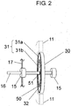
- Fig. 2 is a diagram that schematically shows the principal portions of the brushless motor shown in Fig. 1 .
- ferrite resin magnet 32 is disposed in the outermost periphery of rotating body 30, and outer steel core 31a constituting rotor steel core 31, dielectric layer 50, inner steel core 31b constituting rotor steel core 31 are sequentially disposed toward the inner periphery side.
- dielectric layer 50 is a layer formed of the insulating resin. In the present embodiment, this dielectric layer 50 is provided for preventing the electrolytic corrosion.
- Fig. 2 shows an example in which dielectric layer 50 is formed in the ring shape so as to be rotated around shaft 16 between the inner periphery side and the outer periphery side of rotating body 30.
- rotating body 30 has a configuration in which ferrite resin magnet 32, outer steel core 31a, the insulating resin forming dielectric layer 50, and inner steel core 31b are integrally formed. Furthermore, in fastening portion 51 of the inner periphery of inner steel core 31b, rotating body 30 is fastened to shaft 16. As a result, rotor 14 supported by bearing 15 is constituted.
- dielectric layer 50 is a layer formed by the insulating resin which is the insulating material, and insulates and separates outer steel cores 31a from inner steel core 31b in series.
- dielectric layer 50 is formed by the insulating resin having a predetermined permittivity, whereby high frequency current can flow between outer steel core 31a and inner steel core 31b.
- the impedance of rotor 14 is raised so as to approximate the impedance of bracket 17 side. That is, by providing dielectric layer 50 between outer steel core 31a and inner steel core 31b, rotor 14 becomes a configuration in which the electrostatic capacity by dielectric layer 50 is equivalently connected in series, whereby the impedance of rotor 14 can be raised. That is, by raising the impedance of rotor 14, the voltage drop of the high frequency flowing from rotor 14 to shaft 16 becomes larger. In addition, as a result, it is possible to lower the potential generated in shaft 16 by the high frequency current.
- the brushless motor of the present invention reduces the potential difference due to the high frequency current between the outer ring of bearing 15 which is electrically connected to bracket 17, and shaft 16 of the inner ring side of bearing 15. For this reason, the portion between the bearing inner ring and the bearing outer ring is in the state in which the balance is maintained so that the potential difference is decreased in a state of generally low potential, whereby the occurrence of electrolytic corrosion is prevented in the bearing.
- the electrostatic capacity can be changed, so that the impedance of rotor 14 side can be optimally set. That is, by enlarging the thickness (a distance between the electrodes) of the insulating resin which lowers the permittivity of the insulating resin forming dielectric layer 50, or by reducing the electrode area or the like, the electrostatic capacity by dielectric layer 50 can be lowered. In addition, in this manner, by reducing the electrostatic capacity by dielectric layer 50, the impedance of rotor 14 can be raised.
- the permittivity can be lowered.
- the resin generally used as the insulating resin of the electric motor is a resin in which an inorganic filler such as glass fiber reinforces poly butylene terephthalate (hereinafter, referred to as PBT) resin, polyethylene terephthalate (hereinafter, referred to as PET) resin or the like, and the material has a relative permittivity of about 3.5.
- the relative permittivity of the SPS resin is 2.6 in an unreinforced product and 2.8 in a reinforced product, and is lower than the general resin.
- the upper limit of the thickness of the insulating resin is restricted in structure, and in a case where the impedance is low and insufficient in the PBT resin or the like, it is possible to reduce the electrostatic capacity by using the SPS resin.
- rotating body 30 in which dielectric layer 50 is separated into outer steel core 31a and inner steel core 31b, it is possible to integrally mold the rotor steel core and the insulating resin without shaft 16 in the production process. For this reason, as compared to a configuration in which the dielectric layer is provided between the shaft and the rotor steel core, in the configuration as shown in Fig. 2 rotating body 30 can be molded without the shaft, which can raise productivity. Furthermore, in the configuration as shown in Fig. 2 , even if the kind of shaft 16 is changed, shaft 16 can be fixed by the caulking or pressing shaft 16, so that it is easy to correspond to revision of items, which also can improve the productivity.
- Figs. 3 and 4 are drawings showing the specific configuration examples of the rotating body of the brushless motor in the embodiment of the present invention.
- Figs. 3 and 4 show configuration examples in which the rotating body is seen from the top thereof.
- the rotating body shown in Figs. 3 and 4 has dielectric layer 50 of the shape in which a plurality types of arcs with different radial widths in the diameter direction is radially combined between outer steel core 31a and inner steel core 31b in the diameter direction. That is, dielectric layer 50 has a shape in which a convex protrusion shape and a concave protrusion shape repeatedly rotate in at least one of the outer periphery side and the inner periphery side. Furthermore, outer steel core 31a and inner steel core 31b are fitted into dielectric layer 50 of this shape.
- dielectric layer 50 As shown in Fig. 2 , in a case where dielectric layer 50 is a complete ring shape, there is a fear of slipping or the like at the time of rotation. On the contrary to this, by the shape of dielectric layer 50 as shown in Figs, 3 and 4 , a configuration, in which a protrusion for preventing slipping is inserted between dielectric layer 50 and the steel core, is obtained, whereby slipping can be prevented and the rotation strength can be raised.
- the respective protrusions are provided on outer steel core 31a and inner steel core 31b, respectively so that the protrusions for preventing slipping is disposed in a position where they face each other.
- the rotating body shown in Fig. 4 shows a configuration example in which dielectric layer 50 includes the hole portion, which is gap 40 such as an air layer or a hole, in a partial area thereof.
- the rotating body shown in Fig. 4 provides gap 40 in the thick portion so that a decline in maintenance strength of outer steel cores 31a and inner steel core 31b does not increase due to the influence of gap 40.
- gaps 40 of the equivalent or the identical shape are provided at four places so that unbalancing does not increase during rotation.
- the relative permittivity of the air is about 1, it is very small compared to the insulating resin.
- the impedance of the rotor side (the bearing inner ring side) is low and the axial voltage is high even when the SPS resin is used, or in a case where the used amount of the insulating resin is large and the cost is high, it is possible to lower the electrostatic capacity by forming the air layer or the hole in a part of the insulating resin, whereby the impedance of the rotor side (the bearing inner side) can be further raised.
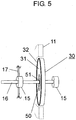
- Fig. 5 is a diagram showing another configuration example of the rotor of the brushless motor in the embodiment of the present invention.
- rotating body 30 shown in Fig. 5 ferrite resin magnet 32 is disposed at the outermost periphery portion, and rotor steel core 31, and dielectric layer 50 formed of the insulating resin are sequentially disposed toward the inner periphery side.
- rotating body 30 shown in Fig. 5 has a configuration in which ferrite resin magnet 32, rotor steel core 31, and the insulating resin forming dielectric layer 50 are integrally formed.
- rotating body 30 is fastened to shaft 16. That is, rotating body 30 is fastened to shaft 16 via dielectric layer 50.
- Rotor 14 may have this configuration, or may have a configuration in which the electrostatic capacity by dielectric layer 50 is connected in series between rotor steel core 31 and shaft 16, whereby the impedance of rotor 14 can be raised.
- the present invention will be specifically described using the embodiment.
- the present invention is not limited to the following embodiment, and unless the gist of the present invention is changed, the present invention is not limited by the embodiment.
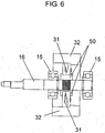
- Fig. 6 is a diagram showing a sectional surface of the rotor of the brushless motor used in the first embodiment. As shown in Fig. 6 , the portion between rotor steel core 31 and shaft 16 is insulated by dielectric layer 50.
- the axial voltage when changing the thickness of the insulating resin forming dielectric layer 50 was measured.
- the insulating resin material was implemented by two types of the PBT resin having the relative permittivity of 3.6 and the SPS resin having the relative permittivity of 2.8. Furthermore, the measurement was performed in a manner in which the same stator is used and the respective rotors are exchanged. As the bearing, Minebea 608 (lubricant of 239 is used) was used.
- Fig. 7 is a diagram showing the measurement method of the axial voltage of the first embodiment.
- a stabilized DC power supply was used, the power supply voltage Vdc of the coil was 391 V, and the power supply voltage Vcc of the control circuit was 15 V, and the measurement was performed under the same driving condition of rpm 1000 r/min.
- the rpm was regulated by the control voltage Vsp, and the brushless motor orientation during operation was a shaft horizontal.
- the measurement of the axial voltage was performed so that a voltage wave form was observed by digital oscilloscope 130 (Techtronics DPO7104) and high voltage differential probe 120 (Techtronics P5205), it was confirmed whether or not wave form collapse was generated, and the measurement voltage from peak to peak was set to the axial voltage.
- the wave form collapse of the axial voltage was classified into three types: a complete wave form collapse, a partial wave form collapse, and no wave form collapse.
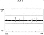
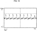
- Figs. 8 to 10 are drawings showing an example of the wave form collapse, Fig. 8 shows complete wave form collapse, Fig. 9 shows partial wave form collapse, and Fig. 10 shows no wave form collapse.
- the measured time indicated by the transverse axis is in the same scale of 50 ⁇ s/div.
- digital oscilloscope 130 is insulated by insulating transformer 140.
- + side 120a of high voltage differential probe 120 is electrically connected to shaft 16 by making the conductor of the lead line in the form of a loop having a diameter of about 15 mm via lead line 110 having a length of about 30 cm and bringing the inner periphery thereof into conductive contact with the outer periphery of shaft 16.
- - side 120b of high voltage differential probe 120 is electrically connected to bracket 17 by bringing a front end of lead line 111 into contact with bracket 17 by use of conductive tape 112 via lead line 111 having a length of about 30 cm. With this configuration, the axial voltage which is the voltage between bracket 17 and shaft 16 was measured.
- the axial voltage was measured in the same method as the first embodiment using the rotor having the same shape as Fig. 6 in which rotor steel core 31 is not insulated from shaft 16.
- Table 1 shows the measurement results of the first embodiment and the first comparison example.
- Table 1 first comparison example first embodiment resin thickness none resin (0mm) 0.2mm 0.5mm 0.75mm 1.0mum 2.0mm 2.5mm 3.5mm PBT resin axial voltage V 35.2 9.9 7.9 6.2 5.9 2.7 3.0 3.1 wave form state complete waveform collapse partial wave form collapse partial wave form collapse none wave form collapse none wave form collapse none wave form collapse none wave form collapse none wave form collapse none wave form collapse none wave form collapse none wave form collapse none wave form collapse none wave form collapse none wave form collapse none wave form collapse none wave form collapse SPS resin axial voltage V - 8.4 5.9 3.7 3.4 3.5 3.5 3.3 waveform state - partial wave form collapse none wave form collapse none wave form collapse none wave form collapse none wave form collapse none wave form collapse none wave form collapse none wave form collapse none wave form collapse none wave form collapse none wave form collapse none wave form collapse none wave form collapse none wave form collapse none wave form collapse none wave form collapse none wave form collapse none wave form collapse none wave form collapse none wave form collapse none wave form collapse
- the axial voltage can be lowered.
- the number of the wave form collapses (insulating breakdown voltage of the oil film in the bearing) significantly decreases, whereby the effect of preventing the occurrence of electrolytic corrosion of the bearing can be further improved.
- the insulating thickness is large, the axial voltage declines, and the wave form collapse is obviated in the region of 6.5 V or less, which makes it possible to suppress the occurrence of electrolytic corrosion of the bearing.
- the SPS resin in the insulating material it is possible to lower the axial voltage in the same insulating thickness, compared to a case using the PBT resin.
- the measurement of the impedance was performed by the same brushless motor as the first embodiment.
- NF circuit design block LCR meter ZM2353 and test lead 2325A were used to measure the impedance of the power supply voltage Vdc between the lead line of the coil and shaft 16.
- the brushless motor orientation was shaft horizontal and the measurement conditions were a voltage of 1 V and frequency of 10 kHz.
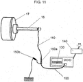
- Fig. 11 shows a diagram of the measurement method of the axial potential of the second embodiment.
- the driving state and the driving condition were the same as the first embodiment, and the measurement of the axial voltage was performed so that a voltage wave form was observed by digital oscilloscope 130 (Techtronics DPO7104) and passive probe 150 (Techtronics P6139A), and the measurement voltage from peak to peak was set to the axial voltage.
- the measured time indicated by the transverse axis was in the same scale of 50 ⁇ s/div similarly to the first embodiment, and digital oscilloscope 130 was insulated by insulating transformer 140.
- probe side 150a of passive probe 150 was electrically connected to shaft 16, by making the conductor of the lead line in the shape of a loop of a diameter of about 15 mm via lead line 110 having a length of about 30 cm, and by bringing the inner periphery thereof into conductive contract with the outer periphery of shaft 16.
- Ground side 150b of passive probe 150 was measured by being connected to the ground of the stabilized power supply used in the power supply of the power supply voltage Vdc of the coil. With this configuration, the axial potential, which is the potential between the ground of the power supply voltage Vdc of the coil and shaft 16, was measured.
- Table 2 shows the measurement results of the second embodiment and the second comparison example.
- Table 2 second comparison example second embodiment resin thickness none resin 0.2mm 0.5mm 0.75mm 1.0mm 2.0mm 2.5mm 3.5mm PBT resin impedance k ⁇ 227 434 455 467 486 506 524 537 axial potential V 170 121 114 112 110 106 104 102 SPS resin impedance k ⁇ - 446 469 490 516 536 543 554 axial potential V - 117 112 108 108 102 102 100
- the impedance of the rotor can be equal to or greater than 400 k ⁇ . Furthermore, the impedance at the same thickness can be raised by making the PBT resin into an SPS resin. That is, in the case of the mold motor in which the stator steel core insulated by the resin and the stator coil are integrally molded by the insulating resin, the impedance between the ground and the bracket (stator side) is about 500 k ⁇ . Thus, by setting the impedance between the ground and the shaft to 400 k ⁇ or more, the axial voltage can be lowered so as to approximate the impedance between the ground and the bracket (stator side).
- the axial potential can be lowered by making the rotor of insulating configuration. Furthermore, by making the PBT resin into the SPS resin, the axial potential at the same thickness can be lowered.
- + side 120a of differential probe 120 is connected to shaft 16 (bearing inner ring) and - side 120b thereof is connected to bracket 17 (bearing outer ring). From the fact that the voltage wave form peaks described in Figs. 8 to 10 point upward, it is understood that the potential of shaft 16 (bearing inner ring) side is higher than that of bracket 17 (berating outer ring). Thus, it is determined that the current flows from the bearing inner ring side to the bearing outer ring side.
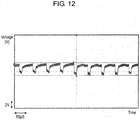
- Fig. 12 is a drawing showing the wave form of the axial voltage when the resin thickness of the insulation is large.
- the wave form'peaks of the axial voltage point downward that is, changed to the opposite direction of the case of Figs. 8 to 10 .
- the wave form peaks of the axial voltage points downward it can be determined that the current flows from the bearing outer ring side to the bearing inner ring. It is determined that the change in direction of the voltage wave form is resulted from the impedance of rotor 14 side being higher than the impedance of stator 10 side due to increasing the insulation thickness of rotor 14.
- the brushless motors of the same specifications of the insulation thickness of 0.2 mm, 1.0 mm, 2.0 mm, and 2.5 mm were prepared, whereby the effect of electrolytic corrosion suppression was confirmed by an electrolytic corrosion endurance test.
- the electrolytic corrosion endurance test was carried out under the no load condition in which the power supply voltage Vdc of the coil was 391 V, the power supply voltage Vcc of the control circuit was 15 V, the control voltage Vsp was 3 V, the rpm was 1000 r/min, the brushless motor orientation was shaft horizontal, and the environmental temperature was 10°C.
- a special bearing in which only one of the seven steel balls of the bearing was a steel ball and the rest were ceramic balls, was attached to the output shaft side (the substrate side).
- the bearing of the ceramic ball specifications was attached to the opposite output shaft side (mold resin side) to make a state of complete insulation.
- the electrolytic corrosion life is the period up to when-an auditory abnormality and the wave form abrasion of the inner part of the bearing were confirmed.
- stator steel core 31 is not insulated from shaft 16 was used to carry out the confirmation of the current direction and the electrolytic corrosion endurance test in the same method as the third embodiment.
- Table 3 shows the measurement results of the third embodiment and the third comparison example.
- the electrolytic corrosion life can be two or three times longer than the related art.
- the axial voltage equal to or less than 6.5 V to obviate the wave form collapse
- the electrolytic corrosion life can be two or three times longer than that of the related art.
- the impedance between the power supply lead line and the shaft is about 500 k ⁇ .
- the impedance between the ground and the shaft (rotor side) is made equal to or greater than 520 k ⁇ , the impedance between the ground and the shaft (rotor side) becomes higher than that between the ground and the bracket (stator side), the current can flow from the bearing outer ring to the bearing inner ring.
- the rotating body of the configuration as shown in Fig. 3 and the rotating body of the configuration as shown in Fig. 4 were used as the same stator used in the first embodiment, respectively to measure the axial voltage by the same method as the first embodiment. Furthermore, the impedance and the axial potential were measure by the same method as the second embodiment.
- the PBT resin was used for the insulating material forming dielectric layer 50.
- the minimum thickness of the resin was 2. 5 mm, and the protrusion for preventing the revolution was provided in outer steel core 31a and inner steel core 31b, respectively.
- the measurement result of the axial voltage, the impedance and the axial potential of the 2.5 mm thickness insulation specifications of the PBT resin produced in the first embodiment were set to the comparison example.
- Table 4 shows the measurement results of the fourth embodiment and the fourth comparison example.
- Table 4 fourth comparison example fourth embodiment shaft insulation division steel core insulation division steel core insulation + gap resin thickness 2.5mm 2.5mm 2.5mm PBT resin axial voltage V 3.0 3.3 3.5 wave form state none wave form collapse none wave form collapse none wave form collapse impedance K ⁇ 524 522 537 axial potential 104 104 102
- the impedance is raised, whereby the axial potential can be reduced.
- the electric motor of the present invention has an effect in which the axial voltage is reduced compared to the electric motor of the related art, so that the impedance can be raised and the axial potential can also be reduced, which is excellent in the prevention of the occurrence of the bearing electrolytic corrosion of the electric motor
- Fig. 13 is a schematic diagram of an indoor air conditioner as electric machinery in the second embodiment of the present invention.
- brushless motor 201 is loaded in a case of indoor air conditioner 210.
- Cross flow fan 212 is mounted on a rotation shaft of brushless motor 201.
- Brushless motor 201 is driven by motor drive apparatus 213.
- motor drive apparatus 213 By the electric current application from motor drive apparatus 213, brushless motor 213 rotates, and cross flow fan 212 rotates accordingly.
- cross flow fan 212 By the rotation of cross flow fan 212, the air, which has been subjected to air conditioning by a heat exchanger (not shown) as an indoor machine, is sent indoors.
- the electric motor shown in the above-mentioned embodiment can be applied.
- the electric machinery of the present invention includes the brushless motor and the case with the brushless motor loaded thereon, the electric motor of the present invention is adopted as the brushless motor.
- the brushless motor loaded on the indoor air conditioner was adopted.
- the present invention can be applied to electric motors loaded on the other electric machineries, for example, a brushless motor used on various home machinery, a brushless motor loaded on various information machines, and a brushless motor used in industrial machinery.
- the electric motor of the present invention includes the stator having the stator steel cores around which the coil is wound; the rotor which includes a rotating body that holds a plurality of permanent magnets in the circumferential direction to face the stator and a shaft that fastens the rotating body so as to penetrate the center of the rotating body; a bearing for supporting the shaft; and a bracket for fixing the bearing, and has a configuration in which a dielectric layer is provided between the shaft and an outer periphery of the rotating body.
- the electric motor of the present invention it is possible to provide an electric motor which prevents the occurrence of electrolytic corrosion in the bearing. Furthermore, by building the electric motor of the present invention into an electric machinery, it is possible to provide an electric machinery including an electric motor which prevents the occurrence of electrolytic corrosion in the bearing.
- the inner rotor type electric motor in which the rotor is disposed rotatably at the inner periphery side of the stator, has been described, the same effect can be achieved even by providing the dielectric layer as mentioned above in an outer rotor type in which the rotor is disposed at the outer periphery side of the stator, and a twin rotor type electric motor in which the rotors are disposed at the both side of the inner periphery and the outer periphery.
- the electric motor of the present invention can reduce the axial voltage and is optimal for preventing the occurrence of electrolytic corrosion of the bearing. For this reason, it is effective for the electric machinery in which the low cost and the high life of the electric motor are further required, for example, the electric motor loaded on an indoor air conditioner, an outdoor air conditioner, a water heater, an air cleaner or the like.
Landscapes
- Engineering & Computer Science (AREA)
- Power Engineering (AREA)
- Motor Or Generator Frames (AREA)
- Insulation, Fastening Of Motor, Generator Windings (AREA)
Description
- The present invention relates to an electric motor, particularly, an electric motor which is improved so as to prevent the occurrence of electrolytic corrosion of a bearing.
- Recently, an electric motors often adopt a type of drive by an inverter of a pulse width modulation type (hereinafter, referred to as PWM type). In the case of the inverter driving of the PWM type, since the neutral point potential of a coil does not become zero, the potential difference (hereinafter, referred to as the axial voltage) is generated between the outer ring and the inner ring of a bearing. The axial voltage includes a high frequency component by the switching. Thus, when the axial voltage reaches the insulating breakdown voltage of an oil film in the bearing, the minute current flows in the bearing, whereby the electrolytic corrosion is generated in the bearing. In a case where the electrolytic corrosion proceeds, a wave-shaped abrasion phenomenon is generated in the bearing inner ring or the bearing outer ring or the bearing ball and may lead to an abnormal sound, which becomes one main cause of defects in the electric motor.
- In the related art, in order to prevent the electrolytic corrosion, the following measures are considered.
- (1) to put the bearing inner ring and the bearing outer ring in a conduction state.
- (2) to put the bearing inner ring and the bearing outer ring in a insulating state.
- (3) to reduce the axial voltage.
- As a specific method of (1), a lubricant for the bearing can be conductive. The conductive lubricant has a problem in that the conductivity deteriorates as time goes on or the sliding reliability is insufficient. Moreover, a method of installing a brush on the rotation axis, making the conduction state can also be considered, but this method also has a problem such as a brush abrasion powder or a need for a space.
- As a specific method of (2), changing a steel ball in the bearing to a ceramic ball can be included. This method has a very high electrolytic corrosion prevention effect, but has a problem of high costs; therefore it cannot be adopted in a general-purpose electric motor.
- As a specific method of (3), a method of reducing the axial voltage by short-circuiting a stator steel core and a bracket to change the electrostatic capacity is well known in the related art (for example, see prior art
publication JP 2007-159302A - Impedance when the electrostatic capacity and the resistance are connected with each other in parallel is indicated by the relation expression of Z=1/jωC+R. Herein, Z refers to impedance, j refers to an imaginary number, ω is a angular frequency, C refers an electrostatic capacity, and R refers to a resistance. As is apparent from the expression, if the electrostatic capacity rises or the resistance drops, the impedance drops. On the contrary, if the electrostatic capacity drops and the resistance rises, the impedance rises.
- In
JP 2007-159302A - That is, generally, in an electric motor, which is used in places where water is used such as washing machines and a dish washing and drying machine and which has a fear of an electric shock, it is necessary to add an separate insulation (hereinafter, referred to an additional insulation) in addition to the insulation of a charge portion (hereinafter, referred to as basic insulation). On the other hand, except for those situations, since electric motors used in indoor air conditioners, outdoor air conditioners, water heaters, air cleaners or the like do not have a fear of electric shock, the additional insulation is unnecessary. Thus, since the electric motors used in the indoor air conditioners, outdoor air conditioners, water heaters, air cleaners or the like do not have the rotor of the insulation configuration, the impedance of the rotor side (the bearing inner ring side) is in a low state. On the contrary, since the stator side (the bearing outer ring side) has the insulation configuration, the impedance is in a high state. In this case, since the potential of the bearing inner ring side is high, while the potential of the bearing outer ring side is low, there is an unbalanced state, whereby the high axial voltage is generated. In addition, there was a possibility in which the electrolytic corrosion could be generated in the bearing due to the high axial voltage.
- In order to avoid this state,
JP 2007-159302A - However, the method of the related art like
JP 2007-159302A - Further, plural embodiments of electric motors, wherein a dielectric layer is provided between a shaft and a rotating body that is attached to the shaft are described in documents
US 2005/253480 A1 ,JP 56 103938 A US 2007/290570 A1 ,US 2002/153783 A1 ,JP 2005 198374 A JP 61 049570 U JP 11 178294 A - The present invention aims to provide an electric motor which prevents the occurrence of electrolytic corrosion in the bearing and electric machinery equipped therewith.
- This is achieved by the features of the independent claims.
- As described above, according to the electric motor of the present invention, the impedance of the rotor side (the bearing inner ring side) is raised to approximate the impedance of the stator side (the bearing outer ring side), whereby it is possible to hold the balance of the high frequency potential of the bearing inner ring side and the bearing outer ring side.
- Furthermore, the dielectric layer is an insulating material for preventing the electrolytic corrosion.
- With this configuration, through the dielectric layer provided between the shaft and the outer periphery of the rotating body, there is provided a configuration in which the electrostatic capacity by the dielectric layer is equivalently connected in series in the low impedance rotor, and therefore the configuration makes it possible to raise the impedance of the rotor side. In this manner, if the impedance of the rotor side is raised, it can approximate the high impedance of the stator side. As a result, it is possible to hold the balance so that the high frequency potentials of the bearing inner ring side and the bearing outer ring side are identical to each other. In this manner, it is possible to reduce the potential difference between the inner ring and the outer ring. For this reason, it is possible to prevent the occurrence of the electrolytic corrosion bearing generated by high frequency due to PWM or the like. Moreover, by changing the width or the material of the dielectric layer, the electrostatic capacity can be changed. As a result, it is also possible to optimally set the impedance of the rotor side. Furthermore, the dielectric layer refers to a layer which intentionally changes the permittivity and the thickness of the dielectric or the surface area of the conductive material (electrode) abutting the dielectric, and intends to interpose a dielectric element between the shaft and the rotating body.
- Furthermore, in the electric motor of the present invention, the dielectric layer is an insulating resin, for example, syndiotactic polystyrene resin.
- By using a syndiotactic polystyrene (hereinafter, referred to as SPS) resin in the insulating resin, the permittivity can be lowered. As a result, even if the thickness of the insulating resin is small, the impedance of the rotor side can be further raised.
- The electric motor of the present invention has a configuration in which the dielectric layer is provided between the inner periphery side and the outer periphery side of the rotating body so as to surround the shaft.
- The electric motor of the present invention may have a configuration in which the rotating body has an outer steel core constituting an outer periphery portion, an inner steel core constituting an inner periphery portion fastened to the shaft, and the dielectric layer, and the outer steel core and the inner steel core are fixed via the dielectric layer.
- With this configuration, the structure of the rotating body can be easily produced, so that the productivity of the rotor can be improved.
- The electric motor of the present invention may be arranged so that the dielectric layer insulates and separates the inner side from the outer side.
- In the electric motor of the present invention, the dielectric layer may include a hole portion.
- In this manner, by forming an air layer or hole as the hole portion in a part of the dielectric layer, the permittivity can be reduced, which makes possible to further raise the impedance of the rotor side.
- Furthermore, in the electric motor of the present invention, the dielectric layer may have a shape in which a plurality of types of arcs with different radial direction widths is combined.
- Moreover, the electric motor of the present invention has a configuration in which the rotor is arranged rotatably in the inner periphery side of the stator.
- Furthermore, the electric motor of the present invention provides the dielectric layer so that the impedance between the stator steel core and the shaft rises, thereby setting the potential difference between the outer ring and the inner ring of the bearing when being driven to 10 V or less. Moreover, the electric motor of the present invention sets the impedance between a power supply lead line and the shaft to 400 kΩ or more, or 520 kΩ or more.
- Furthermore, the electric machinery of the present invention is loaded with the above-mentioned electric motor.
-
-
Fig. 1 is a configuration diagram showing a section of a brushless motor in a first embodiment in the present invention. -
Fig. 2 is a diagram that schematically shows principal parts of the motor. -
Fig. 3 is a diagram showing a specific configuration example of a rotating body of the motor. -
Fig. 4 is a diagram showing specific another configuration example of the rotating body of the motor. -
Fig. 5 is a diagram showing another configuration example of a rotor of the motor. -
Fig. 6 is a diagram showing a section of the rotor of the brushless motor used in the first embodiment. -
Fig. 7 is a diagram showing a measurement method of an axial voltage of the first embodiment. -
Fig. 8 is a diagram showing an example of a complete wave form collapse. -
Fig. 9 is a diagram showing an example of a partial wave form collapse. -
Fig. 10 is a diagram showing an example of none wave form collapse. -
Fig. 11 is a diagram showing a measurement method of an axial potential of a second embodiment. -
Fig. 12 is a diagram showing a wave form of the axial voltage when insulating resin thickness is large. -
Fig. 13 is a schematic diagram showing a configuration of an indoor air conditioner as an example of electric machinery in the second embodiment of the present invention. -
- 10
- stator
- 11
- stator steel core
- 12
- stator coil
- 13
- insulating resin
- 14
- rotor
- 15
- bearing
- 16
- shaft
- 17
- bracket
- 18
- print substrate
- 20
- ground line
- 21
- resin (insulator)
- 30
- rotating body
- 31
- rotor steel core
- 31a
- outer steel core
- 31b
- inner steel core
- 32
- magnet
- 40
- gap (hole portion)
- 50
- dielectric layer
- 110, 111
- lead lines
- 112
- conductive tape
- 120
- differential probe
- 130
- digital oscilloscope
- 140
- insulating transformer
- 150
- passive probe
- 201
- brushless motor
- 210
- indoor air conditioner
- 212
- cross flow fan
- 213
- motor driver
- Hereinafter, an electric motor and electric machinery equipped therewith of the present invention will be described using the drawings.
-
Fig. 1 is a configuration diagram showing a section of an electric motor in a first embodiment. In the present embodiment, a description will be given of an example of an electric motor which is loaded in an air conditioner as electric machinery and is a brushless motor for driving a blast fan. Furthermore, in the present embodiment, an example of an inner rotor type of an electric motor in which a rotor is rotatably disposed in an inner periphery side of a stator. - In
Fig. 1 ,stator 10 is configured by moldingstator steel core 11 around whichstator coil 12 is wounded, with insulatingresin 13 that is a mold material for integral .molding. Furthermore, betweenstator steel core 11 andstator coil 12,resin 21 as an insulator for insulatingstator steel core 11 is disposed. -
Rotor 14 is inserted into an inner side ofstator 10 via a gap.Stator 14 has disc-shapedrotating body 30 includingrotor steel core 31, andshaft 16 which fastens rotatingbody 30 so as to penetrate the center of rotatingbody 30.Rotor steel core 31 maintains a plurality of permanent magnets in the circumferential direction to face the inner periphery side ofstator 10.Fig. 1 shows a configuration example in whichrotor steel core 31 is formed integrally withferrite resin magnet 32 which is a permanent magnet. In this manner, the inner periphery side ofstator 10 is arranged so as to face the outer periphery side of rotatingbody 30. - Two
bearings 15 for supportingshaft 16 are mounted onshaft 16 ofrotor 14.Bearings 15 are bearings having a plurality of steel balls. One of twobearings 15 is fixed to insulatingresin 13 for integrally molding, and the other is fixed tometallic bracket 17. By the configuration described above,shaft 16 is supported by twobearings 15, so thatrotor 14 freely rotates. - In addition, the brushless motor is equipped with
print substrate 18 with a drive circuit installed thereon. Afterprint substrate 18 is equipped, by pressingbracket 17 intostator 10, the brushless motor is formed. A lead line for applying the power supply voltage of the coil, a power supply voltage and a control voltage of a control circuit, andground line 20 of the control circuit are connected to printsubstrate 18. - In addition, in the present embodiment, it is characterized in that
dielectric layer 50 is provided in rotatingbody 30 becoming a portion betweenshaft 16 and the outer periphery of rotatingbody 30. -
Fig. 2 is a diagram that schematically shows the principal portions of the brushless motor shown inFig. 1 . As shown inFig. 2 ,ferrite resin magnet 32 is disposed in the outermost periphery of rotatingbody 30, andouter steel core 31a constitutingrotor steel core 31,dielectric layer 50,inner steel core 31b constitutingrotor steel core 31 are sequentially disposed toward the inner periphery side. Furthermore,dielectric layer 50 is a layer formed of the insulating resin. In the present embodiment, thisdielectric layer 50 is provided for preventing the electrolytic corrosion.Fig. 2 shows an example in whichdielectric layer 50 is formed in the ring shape so as to be rotated aroundshaft 16 between the inner periphery side and the outer periphery side of rotatingbody 30. In this manner, rotatingbody 30 has a configuration in whichferrite resin magnet 32,outer steel core 31a, the insulating resin formingdielectric layer 50, andinner steel core 31b are integrally formed. Furthermore, in fasteningportion 51 of the inner periphery ofinner steel core 31b, rotatingbody 30 is fastened toshaft 16. As a result,rotor 14 supported by bearing 15 is constituted. - In
rotor body 30,dielectric layer 50 is a layer formed by the insulating resin which is the insulating material, and insulates and separatesouter steel cores 31a frominner steel core 31b in series. On the other hand,dielectric layer 50 is formed by the insulating resin having a predetermined permittivity, whereby high frequency current can flow betweenouter steel core 31a andinner steel core 31b. - However, in a case where
dielectric layer 50 is not provided, as described above, the impedance between the brackets based on the stator steel core is high, and, on the other hand, the impedance between the shafts which are electrically connected to the rotating body, is low. With respect to an equivalent circuit having this impedance component, high frequency current or the like of the pulse width modulation generated in the stator steel core or the like flows in. For this reason, between the outer ring of the bearing which is electrically connected to the bracket, and the shaft of the inner ring of the bearing, the potential difference due to the high frequency current is generated. - In the present embodiment, by providing
dielectric layer 50 as shown inFig. 2 in rotatingbody 30 ofrotor 14 with low impedance, the impedance ofrotor 14 is raised so as to approximate the impedance ofbracket 17 side. That is, by providingdielectric layer 50 betweenouter steel core 31a andinner steel core 31b,rotor 14 becomes a configuration in which the electrostatic capacity bydielectric layer 50 is equivalently connected in series, whereby the impedance ofrotor 14 can be raised. That is, by raising the impedance ofrotor 14, the voltage drop of the high frequency flowing fromrotor 14 toshaft 16 becomes larger. In addition, as a result, it is possible to lower the potential generated inshaft 16 by the high frequency current. Based on this principle, the brushless motor of the present invention reduces the potential difference due to the high frequency current between the outer ring of bearing 15 which is electrically connected tobracket 17, andshaft 16 of the inner ring side of bearing 15. For this reason, the portion between the bearing inner ring and the bearing outer ring is in the state in which the balance is maintained so that the potential difference is decreased in a state of generally low potential, whereby the occurrence of electrolytic corrosion is prevented in the bearing. - Furthermore, by changing the width or the material of
dielectric layer 50, the electrostatic capacity can be changed, so that the impedance ofrotor 14 side can be optimally set. That is, by enlarging the thickness (a distance between the electrodes) of the insulating resin which lowers the permittivity of the insulating resin formingdielectric layer 50, or by reducing the electrode area or the like, the electrostatic capacity bydielectric layer 50 can be lowered. In addition, in this manner, by reducing the electrostatic capacity bydielectric layer 50, the impedance ofrotor 14 can be raised. - Furthermore, by using a syndiotactic polystyrene (hereinafter, referred to as SPS) resin as the insulating resin forming
dielectric layer 50, the permittivity can be lowered. As a result, even if the thickness of the insulating resin is small, the impedance ofrotor 14 can be further raised. That is, the resin generally used as the insulating resin of the electric motor is a resin in which an inorganic filler such as glass fiber reinforces poly butylene terephthalate (hereinafter, referred to as PBT) resin, polyethylene terephthalate (hereinafter, referred to as PET) resin or the like, and the material has a relative permittivity of about 3.5. On the contrary, the relative permittivity of the SPS resin is 2.6 in an unreinforced product and 2.8 in a reinforced product, and is lower than the general resin. Thus, the upper limit of the thickness of the insulating resin is restricted in structure, and in a case where the impedance is low and insufficient in the PBT resin or the like, it is possible to reduce the electrostatic capacity by using the SPS resin. - In addition, as shown in
Fig. 2 , by the configuration of rotatingbody 30 in whichdielectric layer 50 is separated intoouter steel core 31a andinner steel core 31b, it is possible to integrally mold the rotor steel core and the insulating resin withoutshaft 16 in the production process. For this reason, as compared to a configuration in which the dielectric layer is provided between the shaft and the rotor steel core, in the configuration as shown inFig. 2 rotating body 30 can be molded without the shaft, which can raise productivity. Furthermore, in the configuration as shown inFig. 2 , even if the kind ofshaft 16 is changed,shaft 16 can be fixed by the caulking or pressingshaft 16, so that it is easy to correspond to revision of items, which also can improve the productivity. -
Figs. 3 and 4 are drawings showing the specific configuration examples of the rotating body of the brushless motor in the embodiment of the present invention.Figs. 3 and 4 show configuration examples in which the rotating body is seen from the top thereof. The rotating body shown inFigs. 3 and 4 hasdielectric layer 50 of the shape in which a plurality types of arcs with different radial widths in the diameter direction is radially combined betweenouter steel core 31a andinner steel core 31b in the diameter direction. That is,dielectric layer 50 has a shape in which a convex protrusion shape and a concave protrusion shape repeatedly rotate in at least one of the outer periphery side and the inner periphery side. Furthermore,outer steel core 31a andinner steel core 31b are fitted intodielectric layer 50 of this shape. - As shown in
Fig. 2 , in a case wheredielectric layer 50 is a complete ring shape, there is a fear of slipping or the like at the time of rotation. On the contrary to this, by the shape ofdielectric layer 50 as shown inFigs, 3 and 4 , a configuration, in which a protrusion for preventing slipping is inserted betweendielectric layer 50 and the steel core, is obtained, whereby slipping can be prevented and the rotation strength can be raised. In a more specific example, the respective protrusions are provided onouter steel core 31a andinner steel core 31b, respectively so that the protrusions for preventing slipping is disposed in a position where they face each other. - Furthermore, the rotating body shown in
Fig. 4 shows a configuration example in whichdielectric layer 50 includes the hole portion, which is gap 40 such as an air layer or a hole, in a partial area thereof. The rotating body shown inFig. 4 provides gap 40 in the thick portion so that a decline in maintenance strength ofouter steel cores 31a andinner steel core 31b does not increase due to the influence of gap 40. Furthermore, gaps 40 of the equivalent or the identical shape are provided at four places so that unbalancing does not increase during rotation. However, since the relative permittivity of the air is about 1, it is very small compared to the insulating resin. Thus, in a case where the upper limit of the thickness of the insulating resin is restricted in structure, whereby the impedance of the rotor side (the bearing inner ring side) is low and the axial voltage is high even when the SPS resin is used, or in a case where the used amount of the insulating resin is large and the cost is high, it is possible to lower the electrostatic capacity by forming the air layer or the hole in a part of the insulating resin, whereby the impedance of the rotor side (the bearing inner side) can be further raised. -
Fig. 5 is a diagram showing another configuration example of the rotor of the brushless motor in the embodiment of the present invention. - In rotating
body 30 shown inFig. 5 ,ferrite resin magnet 32 is disposed at the outermost periphery portion, androtor steel core 31, anddielectric layer 50 formed of the insulating resin are sequentially disposed toward the inner periphery side. As described above, rotatingbody 30 shown inFig. 5 has a configuration in whichferrite resin magnet 32,rotor steel core 31, and the insulating resin formingdielectric layer 50 are integrally formed. Furthermore, in fasteningportion 51 of the inner periphery ofdielectric layer 50, rotatingbody 30 is fastened toshaft 16. That is, rotatingbody 30 is fastened toshaft 16 viadielectric layer 50.Rotor 14 may have this configuration, or may have a configuration in which the electrostatic capacity bydielectric layer 50 is connected in series betweenrotor steel core 31 andshaft 16, whereby the impedance ofrotor 14 can be raised. - Hereinafter, the present invention will be specifically described using the embodiment. In addition, the present invention is not limited to the following embodiment, and unless the gist of the present invention is changed, the present invention is not limited by the embodiment.
-
Fig. 6 is a diagram showing a sectional surface of the rotor of the brushless motor used in the first embodiment. As shown inFig. 6 , the portion betweenrotor steel core 31 andshaft 16 is insulated bydielectric layer 50. - By changing the inner diameter of
rotor steel core 31, the axial voltage when changing the thickness of the insulating resin formingdielectric layer 50 was measured. The insulating resin material was implemented by two types of the PBT resin having the relative permittivity of 3.6 and the SPS resin having the relative permittivity of 2.8. Furthermore, the measurement was performed in a manner in which the same stator is used and the respective rotors are exchanged. As the bearing, Minebea 608 (lubricant of 239 is used) was used. -
Fig. 7 is a diagram showing the measurement method of the axial voltage of the first embodiment. When measuring the axial voltage, a stabilized DC power supply was used, the power supply voltage Vdc of the coil was 391 V, and the power supply voltage Vcc of the control circuit was 15 V, and the measurement was performed under the same driving condition of rpm 1000 r/min. In addition, the rpm was regulated by the control voltage Vsp, and the brushless motor orientation during operation was a shaft horizontal. - The measurement of the axial voltage was performed so that a voltage wave form was observed by digital oscilloscope 130 (Techtronics DPO7104) and high voltage differential probe 120 (Techtronics P5205), it was confirmed whether or not wave form collapse was generated, and the measurement voltage from peak to peak was set to the axial voltage.
- Furthermore, the wave form collapse of the axial voltage was classified into three types: a complete wave form collapse, a partial wave form collapse, and no wave form collapse.
-
Figs. 8 to 10 are drawings showing an example of the wave form collapse,Fig. 8 shows complete wave form collapse,Fig. 9 shows partial wave form collapse, andFig. 10 shows no wave form collapse. InFigs. 8 to 10 , the measured time indicated by the transverse axis is in the same scale of 50 µs/div. In addition,digital oscilloscope 130 is insulated by insulatingtransformer 140. - Furthermore, +
side 120a of high voltagedifferential probe 120 is electrically connected toshaft 16 by making the conductor of the lead line in the form of a loop having a diameter of about 15 mm vialead line 110 having a length of about 30 cm and bringing the inner periphery thereof into conductive contact with the outer periphery ofshaft 16. -side 120b of high voltagedifferential probe 120 is electrically connected tobracket 17 by bringing a front end oflead line 111 into contact withbracket 17 by use ofconductive tape 112 vialead line 111 having a length of about 30 cm. With this configuration, the axial voltage which is the voltage betweenbracket 17 andshaft 16 was measured. - The axial voltage was measured in the same method as the first embodiment using the rotor having the same shape as
Fig. 6 in whichrotor steel core 31 is not insulated fromshaft 16. - Table 1 shows the measurement results of the first embodiment and the first comparison example.
Table 1 first comparison example first embodiment resin thickness none resin (0mm) 0.2mm 0.5mm 0.75mm 1.0mum 2.0mm 2.5mm 3.5mm PBT resin axial voltage V 35.2 9.9 7.9 6.2 5.9 2.7 3.0 3.1 wave form state complete waveform collapse partial wave form collapse partial wave form collapse none wave form collapse none wave form collapse none wave form collapse none wave form collapse none wave form collapse SPS resin axial voltage V - 8.4 5.9 3.7 3.4 3.5 3.5 3.3 waveform state - partial wave form collapse none wave form collapse none wave form collapse none wave form collapse none wave form collapse none wave form collapse none wave form collapse - As is apparent form the table 1, by providing
dielectric layer 50, the axial voltage can be lowered. In addition, if the axial voltage is equal to or less than 10 V, the number of the wave form collapses (insulating breakdown voltage of the oil film in the bearing) significantly decreases, whereby the effect of preventing the occurrence of electrolytic corrosion of the bearing can be further improved. Furthermore, as the insulating thickness is large, the axial voltage declines, and the wave form collapse is obviated in the region of 6.5 V or less, which makes it possible to suppress the occurrence of electrolytic corrosion of the bearing. Furthermore, by using the SPS resin in the insulating material, it is possible to lower the axial voltage in the same insulating thickness, compared to a case using the PBT resin. - In the second embodiment, the measurement of the impedance was performed by the same brushless motor as the first embodiment.
- In the measurement of the impedance, NF circuit design block LCR meter ZM2353 and test lead 2325A were used to measure the impedance of the power supply voltage Vdc between the lead line of the coil and
shaft 16. In addition, in the non rotation state, the brushless motor orientation was shaft horizontal and the measurement conditions were a voltage of 1 V and frequency of 10 kHz. - Furthermore, in order to confirm the impedance state during driving, the axial potential during driving was measured.
-
Fig. 11 shows a diagram of the measurement method of the axial potential of the second embodiment. The driving state and the driving condition were the same as the first embodiment, and the measurement of the axial voltage was performed so that a voltage wave form was observed by digital oscilloscope 130 (Techtronics DPO7104) and passive probe 150 (Techtronics P6139A), and the measurement voltage from peak to peak was set to the axial voltage. - The measured time indicated by the transverse axis was in the same scale of 50 µs/div similarly to the first embodiment, and
digital oscilloscope 130 was insulated by insulatingtransformer 140. - Furthermore,
probe side 150a ofpassive probe 150 was electrically connected toshaft 16, by making the conductor of the lead line in the shape of a loop of a diameter of about 15 mm vialead line 110 having a length of about 30 cm, and by bringing the inner periphery thereof into conductive contract with the outer periphery ofshaft 16.Ground side 150b ofpassive probe 150 was measured by being connected to the ground of the stabilized power supply used in the power supply of the power supply voltage Vdc of the coil. With this configuration, the axial potential, which is the potential between the ground of the power supply voltage Vdc of the coil andshaft 16, was measured. - By use of the rotor of the'same configuration as
Fig. 6 in whichrotor steel cores 31 is not insulated fromshaft 16, the impedance and the axial potential were measured in the same manner as the second embodiment. - Table 2 shows the measurement results of the second embodiment and the second comparison example.
Table 2 second comparison example second embodiment resin thickness none resin 0.2mm 0.5mm 0.75mm 1.0mm 2.0mm 2.5mm 3.5mm PBT resin impedance kΩ 227 434 455 467 486 506 524 537 axial potential V 170 121 114 112 110 106 104 102 SPS resin impedance kΩ - 446 469 490 516 536 543 554 axial potential V - 117 112 108 108 102 102 100 - As is apparent from the table 2, by making the rotor of insulating configuration, the impedance of the rotor can be equal to or greater than 400 kΩ. Furthermore, the impedance at the same thickness can be raised by making the PBT resin into an SPS resin. That is, in the case of the mold motor in which the stator steel core insulated by the resin and the stator coil are integrally molded by the insulating resin, the impedance between the ground and the bracket (stator side) is about 500 kΩ. Thus, by setting the impedance between the ground and the shaft to 400 kΩ or more, the axial voltage can be lowered so as to approximate the impedance between the ground and the bracket (stator side).
- In the same manner as the impedance, the axial potential can be lowered by making the rotor of insulating configuration. Furthermore, by making the PBT resin into the SPS resin, the axial potential at the same thickness can be lowered.
- In the measurement of the first embodiment, +
side 120a ofdifferential probe 120 is connected to shaft 16 (bearing inner ring) and -side 120b thereof is connected to bracket 17 (bearing outer ring). From the fact that the voltage wave form peaks described inFigs. 8 to 10 point upward, it is understood that the potential of shaft 16 (bearing inner ring) side is higher than that of bracket 17 (berating outer ring). Thus, it is determined that the current flows from the bearing inner ring side to the bearing outer ring side. -
Fig. 12 is a drawing showing the wave form of the axial voltage when the resin thickness of the insulation is large. As shown inFig. 12 , by increasing the resin thickness of the insulation, the wave form'peaks of the axial voltage point downward, that is, changed to the opposite direction of the case ofFigs. 8 to 10 . When the wave form peaks of the axial voltage points downward, it can be determined that the current flows from the bearing outer ring side to the bearing inner ring. It is determined that the change in direction of the voltage wave form is resulted from the impedance ofrotor 14 side being higher than the impedance ofstator 10 side due to increasing the insulation thickness ofrotor 14. - Furthermore, in order to confirm electrolytic corrosion prevention effect in the insulation specifications, the brushless motors of the same specifications of the insulation thickness of 0.2 mm, 1.0 mm, 2.0 mm, and 2.5 mm were prepared, whereby the effect of electrolytic corrosion suppression was confirmed by an electrolytic corrosion endurance test.
- In addition, the electrolytic corrosion endurance test was carried out under the no load condition in which the power supply voltage Vdc of the coil was 391 V, the power supply voltage Vcc of the control circuit was 15 V, the control voltage Vsp was 3 V, the rpm was 1000 r/min, the brushless motor orientation was shaft horizontal, and the environmental temperature was 10°C.
- Furthermore, in order to accelerate electrolytic corrosion further than the normal, a special bearing, in which only one of the seven steel balls of the bearing was a steel ball and the rest were ceramic balls, was attached to the output shaft side (the substrate side). The bearing of the ceramic ball specifications was attached to the opposite output shaft side (mold resin side) to make a state of complete insulation.
- Moreover, in the determination of electrolytic corrosion the electrolytic corrosion life is the period up to when-an auditory abnormality and the wave form abrasion of the inner part of the bearing were confirmed.
- The rotor of the same shape as
Fig. 6 in which statorsteel core 31 is not insulated fromshaft 16 was used to carry out the confirmation of the current direction and the electrolytic corrosion endurance test in the same method as the third embodiment. - Table 3 shows the measurement results of the third embodiment and the third comparison example.
Table 3 third comparison example third embodiment resin thickness none resin (0mm) 0.2mm 0.5mm 0.75mm 1.0mm 2.0mm 2.5mm 3.5mm PBT resin axial voltage V 35.2 9.9 7.9 6.2 5.9 2.7 3.0 3.1 direction of the axial voltage wave form upward upward upward upward upward upward downward downward direction of current inner ring → outer ring inner ring → outer ring inner ring → outer ring inner ring → outer ring inner ring → outer ring inner ring → outer ring outer ring → inner ring outer ring → inner ring impedance kΩ 227 434 455 467 486 506 524 537 electrolytic corrosion endurance test result h ≤500 1000-1500 - - 1500-2000 1500-2000 2000≤ - SPS resin axial voltage V - 8.4 5.9 3.7 3.4 3.5 3.5 3.3 direction of the axial voltage wave form - upward upward upward upward downward downward downward direction of current - ilnner ring → outer ring inner ring → outer ring inner ring → outer ring inner ring → outer ring outer ring → inner ring outer ring → inner ring outer ring → inner ring impedance kΩ - 446 469 490 516 536 543 554 electrolytic corrosion endurance test result h - 1000-1500 - - 1500-2000 2000≤ 2000≤ - - As is apparent from the results of table 3, by making the rotor of insulation configuration and the axial voltage equal to or less than 10 V, the electrolytic corrosion life can be two or three times longer than the related art. In addition, by making the axial voltage equal to or less than 6.5 V to obviate the wave form collapse, the electrolytic corrosion life can be two or three times longer than that of the related art.
- In addition, by making the impedance between the power supply lead line and the shaft equal to or greater than 520 kΩ, the impedance of the rotor side becomes higher than that of the stator side, whereby, by changing the direction of the current from the bearing outer ring to the bearing inner ring, electrolytic corrosion life can be four or more times longer. That is, in the case of the molded motor in which the stator steel core insulated by the resin and the stator coil are integrally molded by the insulating resin, the impedance between the ground and the bracket (the stator side) is about 500 kΩ. Thus, since, by making the impedance between the ground and the shaft (rotor side) equal to or greater than 520 kΩ, the impedance between the ground and the shaft (rotor side) becomes higher than that between the ground and the bracket (stator side), the current can flow from the bearing outer ring to the bearing inner ring.
- In a fourth embodiment, the rotating body of the configuration as shown in
Fig. 3 and the rotating body of the configuration as shown inFig. 4 were used as the same stator used in the first embodiment, respectively to measure the axial voltage by the same method as the first embodiment. Furthermore, the impedance and the axial potential were measure by the same method as the second embodiment. - Furthermore, the PBT resin was used for the insulating material forming
dielectric layer 50. The minimum thickness of the resin was 2. 5 mm, and the protrusion for preventing the revolution was provided inouter steel core 31a andinner steel core 31b, respectively. - The measurement result of the axial voltage, the impedance and the axial potential of the 2.5 mm thickness insulation specifications of the PBT resin produced in the first embodiment were set to the comparison example.
- Table 4 shows the measurement results of the fourth embodiment and the fourth comparison example.
Table 4 fourth comparison example fourth embodiment shaft insulation division steel core insulation division steel core insulation + gap resin thickness 2.5mm 2.5mm 2.5mm PBT resin axial voltage V 3.0 3.3 3.5 wave form state none wave form collapse none wave form collapse none wave form collapse impedance KΩ 524 522 537 axial potential 104 104 102 - As is apparent from the result of table 4, even if the shaft insulation as shown in
Fig, 5 is changed to the division steel core insulation as shown inFig, 2 , the axial voltages, the impedances and the axial potentials can respectively be made equal by making the steel core into a shape that does not increase the electrode area. - Furthermore, by providing the hole portion such as gap 40, the impedance is raised, whereby the axial potential can be reduced.
- As is apparent from this result, the electric motor of the present invention has an effect in which the axial voltage is reduced compared to the electric motor of the related art, so that the impedance can be raised and the axial potential can also be reduced, which is excellent in the prevention of the occurrence of the bearing electrolytic corrosion of the electric motor
- In the present embodiment, a configuration of an indoor air conditioner as electric machinery in the present invention will be described.
-
Fig. 13 is a schematic diagram of an indoor air conditioner as electric machinery in the second embodiment of the present invention. - In
Fig. 13 ,brushless motor 201 is loaded in a case ofindoor air conditioner 210.Cross flow fan 212 is mounted on a rotation shaft ofbrushless motor 201.Brushless motor 201 is driven bymotor drive apparatus 213. By the electric current application frommotor drive apparatus 213,brushless motor 213 rotates, and crossflow fan 212 rotates accordingly. By the rotation ofcross flow fan 212, the air, which has been subjected to air conditioning by a heat exchanger (not shown) as an indoor machine, is sent indoors. Herein, asbrushless motor 201, for example, the electric motor shown in the above-mentioned embodiment can be applied. - The electric machinery of the present invention includes the brushless motor and the case with the brushless motor loaded thereon, the electric motor of the present invention is adopted as the brushless motor.
- In the description as mentioned above, as the embodiment of the electric machinery relating to the present invention, the brushless motor loaded on the indoor air conditioner was adopted. However, it is needless to say that the present invention can be applied to electric motors loaded on the other electric machineries, for example, a brushless motor used on various home machinery, a brushless motor loaded on various information machines, and a brushless motor used in industrial machinery.
- As described above, the electric motor of the present invention includes the stator having the stator steel cores around which the coil is wound; the rotor which includes a rotating body that holds a plurality of permanent magnets in the circumferential direction to face the stator and a shaft that fastens the rotating body so as to penetrate the center of the rotating body; a bearing for supporting the shaft; and a bracket for fixing the bearing, and has a configuration in which a dielectric layer is provided between the shaft and an outer periphery of the rotating body. For this reason, via the dielectric layer provided between the shaft and the outer periphery of the rotating body, there is provided a configuration in which the electrostatic capacity by the dielectric layer is equivalently connected in series in the low impedance stator, which makes it possible to raise the impedance of the rotor side. As a result, it is possible to approximate the impedance of the bearing inner ring side to that of the bearing ring outer ring side. Thus, it is possible to hold the balance of high frequency potentials of the bearing inner ring side and the bearing outer ring side, whereby it is possible to prevent the occurrence of electrolytic corrosion bearing generated by high frequency due to PWM or the like. Thus, according to the electric motor of the present invention, it is possible to provide an electric motor which prevents the occurrence of electrolytic corrosion in the bearing. Furthermore, by building the electric motor of the present invention into an electric machinery, it is possible to provide an electric machinery including an electric motor which prevents the occurrence of electrolytic corrosion in the bearing.
- In addition, although the example of the shape shown in
Figs. 2 to 5 as the shape of the dielectric layer has been described in the first embodiment, other shapes may be used, and the impedance of the rotor may be raised by the electrostatic capacity of the dielectric layer. - Furthermore, although the example of the inner rotor type electric motor, in which the rotor is disposed rotatably at the inner periphery side of the stator, has been described, the same effect can be achieved even by providing the dielectric layer as mentioned above in an outer rotor type in which the rotor is disposed at the outer periphery side of the stator, and a twin rotor type electric motor in which the rotors are disposed at the both side of the inner periphery and the outer periphery.
- The electric motor of the present invention can reduce the axial voltage and is optimal for preventing the occurrence of electrolytic corrosion of the bearing. For this reason, it is effective for the electric machinery in which the low cost and the high life of the electric motor are further required, for example, the electric motor loaded on an indoor air conditioner, an outdoor air conditioner, a water heater, an air cleaner or the like.
Claims (12)
- A brushless electric motor which uses pulse width modulation, comprising:a stator (10) including a stator steel core (11) around which a coil (12) is wound, wherein the stator steel core (11) is molded with an insulating resin (13), wherein the coil (12) is driven by an inverter of the pulse width modulation;a rotor (14) which includes a rotating body (30) and a shaft (16) that fastens the rotating body (30) so as to penetrate the center of the rotating body (30);a bearing (15) having a plurality of steel balls, an outer ring and an inner ring for supporting the shaft (16); anda bracket (17) being made of metal for fixing the outer ring of the bearing (15),characterized in that
the bracket is electrically insulated from the stator steel core by the insulating resin (13);
the rotor (14) includes only a single shaft (16) that fastens the rotating body (30);
the rotating body (30) is of an annular shape and is formed of a permanent magnet (32) along a circumferential direction to face the stator (10), an outer steel core (31a) forming an outer periphery of a rotor steel core (31), a dielectric layer (50), and an inner steel core (31 b) forming an inner periphery of the rotor steel core (31), wherein the permanent magnet (32), the outer steel core (31 a) and the inner steel core (31 b) form a concentric arrangement, wherein the permanent magnet (32) surrounds the outer steel core (31a) and the inner steel core (31 b); and
the dielectric layer (50) is provided between the inner steel core (31 b) and the outer steel core (31a) of the rotating body (30) so that the outer steel core (31a), the dielectric layer (50) and the inner steel core (31 b) are placed in this order from a radial outer rim of the rotating body (30) radially inwards to the shaft (16). - The electric motor of claim 1, wherein the dielectric layer (50) is an insulating material suitable for electrolytic corrosion prevention.
- The electric motor of claim 2, wherein the dielectric layer (50) is an insulating resin.
- The electric motor of claim 3, wherein the insulating resin is a syndiotactic polystyrene resin.
- The electric motor of any of claims 1 to 4,
wherein the inner steel core (31b) is fastened to the shaft (16), and
wherein the outer steel core (31 a) and the inner steel core (31 b) are fixed via the dielectric layer (50). - The electric motor of any of claims 1 to 5, wherein the dielectric layer (50) includes a hole portion (40).
- The electric motor of any of claims 1 to 6, wherein the dielectric layer (50) has a shape in which a plurality of types of arcs with different diameter direction widths is combined.
- The electric motor of any of claims 1 to 7, wherein the rotor (14) is disposed rotatably in the inner periphery side of the stator (10).
- The electric motor of any of claims 1 to 8, wherein the potential difference between the outer ring and the inner ring of the bearing (15) when being driven is equal to or less than 10V.
- The electric motor of any of claims 1 to 9, wherein the impedance between a ground and the shaft (16) is equal to or greater than 400 kΩ.
- The electric motor of claim 10, wherein the impedance between a ground and the shaft (16) is equal to or greater than 520 kΩ.
- Electric machinery loaded with the electric motor (201) according to any one of claims 1 to 11.
Applications Claiming Priority (2)
| Application Number | Priority Date | Filing Date | Title |
|---|---|---|---|
| JP2008063685 | 2008-03-13 | ||
| PCT/JP2009/001112 WO2009113311A1 (en) | 2008-03-13 | 2009-03-12 | Electric motor and electrical machinery equipped therewith |
Publications (3)
| Publication Number | Publication Date |
|---|---|
| EP2254220A1 EP2254220A1 (en) | 2010-11-24 |
| EP2254220A4 EP2254220A4 (en) | 2012-08-29 |
| EP2254220B1 true EP2254220B1 (en) | 2017-03-01 |
Family
ID=41064984
Family Applications (1)
| Application Number | Title | Priority Date | Filing Date |
|---|---|---|---|
| EP09720968.8A Active EP2254220B1 (en) | 2008-03-13 | 2009-03-12 | Electric motor and electrical machinery equipped therewith |
Country Status (5)
| Country | Link |
|---|---|
| US (1) | US8552601B2 (en) |
| EP (1) | EP2254220B1 (en) |
| JP (2) | JP5254310B2 (en) |
| CN (1) | CN101971460B (en) |
| WO (1) | WO2009113311A1 (en) |
Families Citing this family (25)
| Publication number | Priority date | Publication date | Assignee | Title |
|---|---|---|---|---|
| EP2378644B1 (en) * | 2009-02-26 | 2016-12-28 | Panasonic Intellectual Property Management Co., Ltd. | Motor and electrical equipment equipped with same |
| JPWO2011043075A1 (en) * | 2009-10-09 | 2013-03-04 | パナソニック株式会社 | Air conditioner |
| JP5493931B2 (en) * | 2010-02-02 | 2014-05-14 | パナソニック株式会社 | Air conditioner |
| CN102884716B (en) * | 2010-05-12 | 2015-08-19 | 松下电器产业株式会社 | Electro-motor and the electric device comprising this electro-motor |
| WO2011141958A1 (en) * | 2010-05-12 | 2011-11-17 | Panasonic Corporation | Electric motor and electric device including the electric motor |
| EP2597189A1 (en) * | 2010-07-21 | 2013-05-29 | Panasonic Corporation | Brushless motor for washing machine and drum-type washing machine provided with same |
| JP5889534B2 (en) * | 2011-02-01 | 2016-03-22 | 日本電産テクノモータ株式会社 | Brushless DC motor |
| US9071090B2 (en) * | 2011-04-27 | 2015-06-30 | Panasonic Intellectual Property Management Co., Ltd. | Motor and electric device including the same |
| JP5502822B2 (en) * | 2011-04-27 | 2014-05-28 | パナソニック株式会社 | Electric motor and electric device including the same |
| JP2014018020A (en) * | 2012-07-11 | 2014-01-30 | Panasonic Corp | Motor and electric apparatus provided with the same |
| JP6248280B2 (en) * | 2012-11-22 | 2017-12-20 | パナソニックIpマネジメント株式会社 | Electric motor and electric device equipped with the electric motor |
| WO2014141656A1 (en) | 2013-03-15 | 2014-09-18 | パナソニック株式会社 | Electric motor and electrical device equipped with electric motor |
| CN105659478B (en) * | 2013-10-21 | 2019-03-29 | 松下知识产权经营株式会社 | Motor and the electric equipment for having the motor |
| KR101668182B1 (en) * | 2015-02-10 | 2016-10-21 | 주식회사 승정 | Method for assembling rotator of motor |
| US10326323B2 (en) | 2015-12-11 | 2019-06-18 | Whirlpool Corporation | Multi-component rotor for an electric motor of an appliance |
| JP6648619B2 (en) * | 2016-04-19 | 2020-02-14 | 株式会社デンソー | Brushless motor |
| JP6332376B2 (en) | 2016-09-21 | 2018-05-30 | 株式会社富士通ゼネラル | Permanent magnet motor |
| US10704180B2 (en) | 2016-09-22 | 2020-07-07 | Whirlpool Corporation | Reinforcing cap for a tub rear wall of an appliance |
| EP3591814B1 (en) * | 2017-02-28 | 2024-07-31 | Panasonic Intellectual Property Management Co., Ltd. | Molded motor |
| US10693336B2 (en) | 2017-06-02 | 2020-06-23 | Whirlpool Corporation | Winding configuration electric motor |
| DE102017130647A1 (en) * | 2017-12-20 | 2019-06-27 | Ebm-Papst Mulfingen Gmbh & Co. Kg | Device for reducing harmful bearing stresses |
| CN112366880B (en) | 2019-07-26 | 2023-11-21 | 广东威灵电机制造有限公司 | Motor and electrical equipment with same |
| US11916447B2 (en) * | 2021-06-07 | 2024-02-27 | Black & Decker Inc. | Overmolded rotor structure |
| US12068639B2 (en) | 2021-06-07 | 2024-08-20 | Black & Decker Inc. | Motor rotor with sleeve for retention of magnet ring |
| CN113394902A (en) * | 2021-06-15 | 2021-09-14 | 珠海格力电器股份有限公司 | Fan motor |
Family Cites Families (29)
| Publication number | Priority date | Publication date | Assignee | Title |
|---|---|---|---|---|
| JPS56103938A (en) | 1980-01-23 | 1981-08-19 | Mitsubishi Electric Corp | Shaft current preventing device for motor |
| JPS6149570U (en) * | 1984-09-03 | 1986-04-03 | ||
| JP2574007B2 (en) * | 1988-08-02 | 1997-01-22 | ファナック株式会社 | Synchronous motor rotor |
| FR2645364B1 (en) * | 1989-04-04 | 1996-01-26 | Banon Louis | SYNCHRONOUS POLYPHASE MACHINE WITH PERMANENT MAGNETS |
| JPH0332333A (en) * | 1989-06-26 | 1991-02-12 | Fanuc Ltd | Radial type rotor structure |
| JP3364960B2 (en) * | 1992-09-04 | 2003-01-08 | 松下電器産業株式会社 | Permanent magnet motor rotor |
| JPH06261507A (en) * | 1993-03-08 | 1994-09-16 | Matsushita Electric Ind Co Ltd | Rotor for induction motor |
| JP3624321B2 (en) | 1994-07-28 | 2005-03-02 | 日本電産シバウラ株式会社 | Electric motor rotor |
| US5704111A (en) * | 1995-05-24 | 1998-01-06 | General Electric Company | Method for making a rotor for an electric motor |
| EP0875091A1 (en) * | 1996-01-18 | 1998-11-04 | Shibaura Engineering Works Company, Ltd. | A motor mounted in a vehicle |
| US6121709A (en) * | 1997-10-16 | 2000-09-19 | Alliedsignal Inc. | Rotor assembly having bonded lamination stack |
| JPH11178294A (en) * | 1997-12-12 | 1999-07-02 | Matsushita Electric Ind Co Ltd | Induction motor |
| US6069421A (en) * | 1999-08-30 | 2000-05-30 | Electric Boat Corporation | Electric motor having composite encapsulated stator and rotor |
| JP3672775B2 (en) | 1999-10-18 | 2005-07-20 | 松下エコシステムズ株式会社 | Brushless motor |
| JP2001268831A (en) | 2000-03-21 | 2001-09-28 | Matsushita Electric Ind Co Ltd | Permanent magnet rotor |
| JP3895095B2 (en) * | 2000-05-09 | 2007-03-22 | 三菱電機株式会社 | Plastic magnet rotor and air conditioner |
| JP2002174228A (en) | 2000-12-06 | 2002-06-21 | Nsk Ltd | Electrolytic corrosion prevention structure for rolling bearing |
| JP3879413B2 (en) | 2001-02-28 | 2007-02-14 | 株式会社日立製作所 | Conveying system and rotating electric machine |
| GB0109847D0 (en) * | 2001-04-21 | 2001-06-13 | Johnson Electric Sa | Motor |
| JP2003113842A (en) * | 2001-10-01 | 2003-04-18 | Koyo Seiko Co Ltd | Insulated bearing |
| JP2005198374A (en) * | 2004-01-05 | 2005-07-21 | Mitsubishi Electric Corp | Dynamo-electric machine |
| JP4565870B2 (en) * | 2004-03-26 | 2010-10-20 | ミネベア株式会社 | Electric pump |
| US20050253480A1 (en) * | 2004-05-14 | 2005-11-17 | Pizzichil William P | Apparatus and method for reducing shaft charge |
| US20050285464A1 (en) * | 2004-06-28 | 2005-12-29 | Orders Marcus D | Method and apparatus for dissipating shaft charge |
| JP2006187144A (en) * | 2004-12-28 | 2006-07-13 | Honda Motor Co Ltd | Electric rotary machine |
| US7365458B2 (en) * | 2005-03-31 | 2008-04-29 | Nidec Shibaura Corporation | Brushless DC motor with molded resin housing |
| JP5076311B2 (en) | 2005-12-07 | 2012-11-21 | パナソニック株式会社 | Brushless motor |
| JP4989067B2 (en) * | 2005-12-14 | 2012-08-01 | 日本電産テクノモータ株式会社 | Brushless DC motor |
| JP4912752B2 (en) * | 2006-05-30 | 2012-04-11 | 日本電産テクノモータホールディングス株式会社 | motor |
-
2009
- 2009-03-12 CN CN2009801087404A patent/CN101971460B/en active Active
- 2009-03-12 EP EP09720968.8A patent/EP2254220B1/en active Active
- 2009-03-12 US US12/922,125 patent/US8552601B2/en active Active
- 2009-03-12 WO PCT/JP2009/001112 patent/WO2009113311A1/en active Application Filing
- 2009-03-12 JP JP2010502727A patent/JP5254310B2/en active Active
-
2011
- 2011-11-25 JP JP2011257544A patent/JP5316629B2/en active Active
Also Published As
| Publication number | Publication date |
|---|---|
| JP5254310B2 (en) | 2013-08-07 |
| CN101971460A (en) | 2011-02-09 |
| JP5316629B2 (en) | 2013-10-16 |
| WO2009113311A1 (en) | 2009-09-17 |
| JP2012039875A (en) | 2012-02-23 |
| US8552601B2 (en) | 2013-10-08 |
| JPWO2009113311A1 (en) | 2011-07-21 |
| US20110043071A1 (en) | 2011-02-24 |
| CN101971460B (en) | 2013-08-07 |
| EP2254220A1 (en) | 2010-11-24 |
| EP2254220A4 (en) | 2012-08-29 |
Similar Documents
| Publication | Publication Date | Title |
|---|---|---|
| EP2254220B1 (en) | Electric motor and electrical machinery equipped therewith | |
| EP2477314B1 (en) | Electric motor and electric device provided therewith | |
| JP5338641B2 (en) | Electric motor and electric device including the same | |
| JP4853572B2 (en) | Electric motor and electric device including the same | |
| EP2355311B1 (en) | Motor and electric device using same | |
| US8987955B2 (en) | Electric motor and electric device including the same | |
| EP2378644B1 (en) | Motor and electrical equipment equipped with same | |
| CN102859845B (en) | Motor and the electric equipment with this motor | |
| US20120286608A1 (en) | Rolling bearing for inverter-driven motor and inverter-driven motor therewith | |
| JP5428347B2 (en) | Electric motor and electric device including the electric motor | |
| US20130300225A1 (en) | Molded motor | |
| WO2011141958A1 (en) | Electric motor and electric device including the electric motor | |
| WO2015001782A1 (en) | Motor and electric device equipped with same |
Legal Events
| Date | Code | Title | Description |
|---|---|---|---|
| PUAI | Public reference made under article 153(3) epc to a published international application that has entered the european phase |
Free format text: ORIGINAL CODE: 0009012 |
|
| 17P | Request for examination filed |
Effective date: 20100906 |
|
| AK | Designated contracting states |
Kind code of ref document: A1 Designated state(s): AT BE BG CH CY CZ DE DK EE ES FI FR GB GR HR HU IE IS IT LI LT LU LV MC MK MT NL NO PL PT RO SE SI SK TR |
|
| AX | Request for extension of the european patent |
Extension state: AL BA RS |
|
| DAX | Request for extension of the european patent (deleted) | ||
| A4 | Supplementary search report drawn up and despatched |
Effective date: 20120801 |
|
| RIC1 | Information provided on ipc code assigned before grant |
Ipc: H02K 29/00 20060101ALI20120726BHEP Ipc: H02K 1/28 20060101AFI20120726BHEP Ipc: H02K 11/00 20060101ALI20120726BHEP Ipc: H02K 5/173 20060101ALI20120726BHEP |
|
| 17Q | First examination report despatched |
Effective date: 20140724 |
|
| RAP1 | Party data changed (applicant data changed or rights of an application transferred) |
Owner name: PANASONIC INTELLECTUAL PROPERTY MANAGEMENT CO., LT |
|
| REG | Reference to a national code |
Ref country code: DE Ref legal event code: R079 Ref document number: 602009044453 Country of ref document: DE Free format text: PREVIOUS MAIN CLASS: H02K0001280000 Ipc: H02K0011400000 |
|
| GRAP | Despatch of communication of intention to grant a patent |
Free format text: ORIGINAL CODE: EPIDOSNIGR1 |
|
| RIC1 | Information provided on ipc code assigned before grant |
Ipc: H02K 5/173 20060101ALN20160805BHEP Ipc: H02K 11/40 20160101AFI20160805BHEP Ipc: H02K 1/30 20060101ALI20160805BHEP Ipc: H02K 1/27 20060101ALN20160805BHEP |
|
| INTG | Intention to grant announced |
Effective date: 20160914 |
|
| RIN1 | Information on inventor provided before grant (corrected) |
Inventor name: MIZUKAMI, HIROFUMI, C/O PANASONIC CORPORATION Inventor name: WATANABE, AKIHIKO, C/O PANASONIC CORPORATION |
|
| STAA | Information on the status of an ep patent application or granted ep patent |
Free format text: STATUS: GRANT OF PATENT IS INTENDED |
|
| GRAS | Grant fee paid |
Free format text: ORIGINAL CODE: EPIDOSNIGR3 |
|
| GRAA | (expected) grant |
Free format text: ORIGINAL CODE: 0009210 |
|
| STAA | Information on the status of an ep patent application or granted ep patent |
Free format text: STATUS: THE PATENT HAS BEEN GRANTED |
|
| AK | Designated contracting states |
Kind code of ref document: B1 Designated state(s): AT BE BG CH CY CZ DE DK EE ES FI FR GB GR HR HU IE IS IT LI LT LU LV MC MK MT NL NO PL PT RO SE SI SK TR |
|
| REG | Reference to a national code |
Ref country code: GB Ref legal event code: FG4D |
|
| REG | Reference to a national code |
Ref country code: CH Ref legal event code: EP Ref country code: AT Ref legal event code: REF Ref document number: 872388 Country of ref document: AT Kind code of ref document: T Effective date: 20170315 |
|
| REG | Reference to a national code |
Ref country code: IE Ref legal event code: FG4D |
|
| REG | Reference to a national code |
Ref country code: DE Ref legal event code: R096 Ref document number: 602009044453 Country of ref document: DE |
|
| REG | Reference to a national code |
Ref country code: NL Ref legal event code: MP Effective date: 20170301 |
|
| REG | Reference to a national code |
Ref country code: LT Ref legal event code: MG4D |
|
| REG | Reference to a national code |
Ref country code: AT Ref legal event code: MK05 Ref document number: 872388 Country of ref document: AT Kind code of ref document: T Effective date: 20170301 |
|
| PG25 | Lapsed in a contracting state [announced via postgrant information from national office to epo] |
Ref country code: LT Free format text: LAPSE BECAUSE OF FAILURE TO SUBMIT A TRANSLATION OF THE DESCRIPTION OR TO PAY THE FEE WITHIN THE PRESCRIBED TIME-LIMIT Effective date: 20170301 Ref country code: FI Free format text: LAPSE BECAUSE OF FAILURE TO SUBMIT A TRANSLATION OF THE DESCRIPTION OR TO PAY THE FEE WITHIN THE PRESCRIBED TIME-LIMIT Effective date: 20170301 Ref country code: NO Free format text: LAPSE BECAUSE OF FAILURE TO SUBMIT A TRANSLATION OF THE DESCRIPTION OR TO PAY THE FEE WITHIN THE PRESCRIBED TIME-LIMIT Effective date: 20170601 Ref country code: HR Free format text: LAPSE BECAUSE OF FAILURE TO SUBMIT A TRANSLATION OF THE DESCRIPTION OR TO PAY THE FEE WITHIN THE PRESCRIBED TIME-LIMIT Effective date: 20170301 Ref country code: GR Free format text: LAPSE BECAUSE OF FAILURE TO SUBMIT A TRANSLATION OF THE DESCRIPTION OR TO PAY THE FEE WITHIN THE PRESCRIBED TIME-LIMIT Effective date: 20170602 |
|
| PG25 | Lapsed in a contracting state [announced via postgrant information from national office to epo] |
Ref country code: AT Free format text: LAPSE BECAUSE OF FAILURE TO SUBMIT A TRANSLATION OF THE DESCRIPTION OR TO PAY THE FEE WITHIN THE PRESCRIBED TIME-LIMIT Effective date: 20170301 Ref country code: LV Free format text: LAPSE BECAUSE OF FAILURE TO SUBMIT A TRANSLATION OF THE DESCRIPTION OR TO PAY THE FEE WITHIN THE PRESCRIBED TIME-LIMIT Effective date: 20170301 Ref country code: SE Free format text: LAPSE BECAUSE OF FAILURE TO SUBMIT A TRANSLATION OF THE DESCRIPTION OR TO PAY THE FEE WITHIN THE PRESCRIBED TIME-LIMIT Effective date: 20170301 Ref country code: BG Free format text: LAPSE BECAUSE OF FAILURE TO SUBMIT A TRANSLATION OF THE DESCRIPTION OR TO PAY THE FEE WITHIN THE PRESCRIBED TIME-LIMIT Effective date: 20170601 Ref country code: ES Free format text: LAPSE BECAUSE OF FAILURE TO SUBMIT A TRANSLATION OF THE DESCRIPTION OR TO PAY THE FEE WITHIN THE PRESCRIBED TIME-LIMIT Effective date: 20170301 |
|
| PG25 | Lapsed in a contracting state [announced via postgrant information from national office to epo] |
Ref country code: NL Free format text: LAPSE BECAUSE OF FAILURE TO SUBMIT A TRANSLATION OF THE DESCRIPTION OR TO PAY THE FEE WITHIN THE PRESCRIBED TIME-LIMIT Effective date: 20170301 |
|
| PG25 | Lapsed in a contracting state [announced via postgrant information from national office to epo] |
Ref country code: IT Free format text: LAPSE BECAUSE OF FAILURE TO SUBMIT A TRANSLATION OF THE DESCRIPTION OR TO PAY THE FEE WITHIN THE PRESCRIBED TIME-LIMIT Effective date: 20170301 Ref country code: EE Free format text: LAPSE BECAUSE OF FAILURE TO SUBMIT A TRANSLATION OF THE DESCRIPTION OR TO PAY THE FEE WITHIN THE PRESCRIBED TIME-LIMIT Effective date: 20170301 Ref country code: RO Free format text: LAPSE BECAUSE OF FAILURE TO SUBMIT A TRANSLATION OF THE DESCRIPTION OR TO PAY THE FEE WITHIN THE PRESCRIBED TIME-LIMIT Effective date: 20170301 Ref country code: CZ Free format text: LAPSE BECAUSE OF FAILURE TO SUBMIT A TRANSLATION OF THE DESCRIPTION OR TO PAY THE FEE WITHIN THE PRESCRIBED TIME-LIMIT Effective date: 20170301 Ref country code: SK Free format text: LAPSE BECAUSE OF FAILURE TO SUBMIT A TRANSLATION OF THE DESCRIPTION OR TO PAY THE FEE WITHIN THE PRESCRIBED TIME-LIMIT Effective date: 20170301 |
|
| REG | Reference to a national code |
Ref country code: CH Ref legal event code: PL |
|
| PG25 | Lapsed in a contracting state [announced via postgrant information from national office to epo] |
Ref country code: IS Free format text: LAPSE BECAUSE OF FAILURE TO SUBMIT A TRANSLATION OF THE DESCRIPTION OR TO PAY THE FEE WITHIN THE PRESCRIBED TIME-LIMIT Effective date: 20170701 Ref country code: PL Free format text: LAPSE BECAUSE OF FAILURE TO SUBMIT A TRANSLATION OF THE DESCRIPTION OR TO PAY THE FEE WITHIN THE PRESCRIBED TIME-LIMIT Effective date: 20170301 Ref country code: PT Free format text: LAPSE BECAUSE OF FAILURE TO SUBMIT A TRANSLATION OF THE DESCRIPTION OR TO PAY THE FEE WITHIN THE PRESCRIBED TIME-LIMIT Effective date: 20170703 |
|
| REG | Reference to a national code |
Ref country code: DE Ref legal event code: R097 Ref document number: 602009044453 Country of ref document: DE |
|
| REG | Reference to a national code |
Ref country code: IE Ref legal event code: MM4A |
|
| PLBE | No opposition filed within time limit |
Free format text: ORIGINAL CODE: 0009261 |
|
| STAA | Information on the status of an ep patent application or granted ep patent |
Free format text: STATUS: NO OPPOSITION FILED WITHIN TIME LIMIT |
|
| REG | Reference to a national code |
Ref country code: FR Ref legal event code: ST Effective date: 20171228 |
|
| PG25 | Lapsed in a contracting state [announced via postgrant information from national office to epo] |
Ref country code: MC Free format text: LAPSE BECAUSE OF FAILURE TO SUBMIT A TRANSLATION OF THE DESCRIPTION OR TO PAY THE FEE WITHIN THE PRESCRIBED TIME-LIMIT Effective date: 20170301 Ref country code: FR Free format text: LAPSE BECAUSE OF NON-PAYMENT OF DUE FEES Effective date: 20170502 Ref country code: DK Free format text: LAPSE BECAUSE OF FAILURE TO SUBMIT A TRANSLATION OF THE DESCRIPTION OR TO PAY THE FEE WITHIN THE PRESCRIBED TIME-LIMIT Effective date: 20170301 Ref country code: LU Free format text: LAPSE BECAUSE OF NON-PAYMENT OF DUE FEES Effective date: 20170312 |
|
| 26N | No opposition filed |
Effective date: 20171204 |
|
| GBPC | Gb: european patent ceased through non-payment of renewal fee |
Effective date: 20170601 |
|
| PG25 | Lapsed in a contracting state [announced via postgrant information from national office to epo] |
Ref country code: LI Free format text: LAPSE BECAUSE OF NON-PAYMENT OF DUE FEES Effective date: 20170331 Ref country code: SI Free format text: LAPSE BECAUSE OF FAILURE TO SUBMIT A TRANSLATION OF THE DESCRIPTION OR TO PAY THE FEE WITHIN THE PRESCRIBED TIME-LIMIT Effective date: 20170301 Ref country code: IE Free format text: LAPSE BECAUSE OF NON-PAYMENT OF DUE FEES Effective date: 20170312 Ref country code: CH Free format text: LAPSE BECAUSE OF NON-PAYMENT OF DUE FEES Effective date: 20170331 |
|
| REG | Reference to a national code |
Ref country code: BE Ref legal event code: MM Effective date: 20170331 |
|
| PG25 | Lapsed in a contracting state [announced via postgrant information from national office to epo] |
Ref country code: GB Free format text: LAPSE BECAUSE OF NON-PAYMENT OF DUE FEES Effective date: 20170601 |
|
| PG25 | Lapsed in a contracting state [announced via postgrant information from national office to epo] |
Ref country code: BE Free format text: LAPSE BECAUSE OF NON-PAYMENT OF DUE FEES Effective date: 20170331 |
|
| PG25 | Lapsed in a contracting state [announced via postgrant information from national office to epo] |
Ref country code: MT Free format text: LAPSE BECAUSE OF NON-PAYMENT OF DUE FEES Effective date: 20170312 |
|
| PG25 | Lapsed in a contracting state [announced via postgrant information from national office to epo] |
Ref country code: HU Free format text: LAPSE BECAUSE OF FAILURE TO SUBMIT A TRANSLATION OF THE DESCRIPTION OR TO PAY THE FEE WITHIN THE PRESCRIBED TIME-LIMIT; INVALID AB INITIO Effective date: 20090312 |
|
| PG25 | Lapsed in a contracting state [announced via postgrant information from national office to epo] |
Ref country code: CY Free format text: LAPSE BECAUSE OF NON-PAYMENT OF DUE FEES Effective date: 20170301 |
|
| PG25 | Lapsed in a contracting state [announced via postgrant information from national office to epo] |
Ref country code: MK Free format text: LAPSE BECAUSE OF FAILURE TO SUBMIT A TRANSLATION OF THE DESCRIPTION OR TO PAY THE FEE WITHIN THE PRESCRIBED TIME-LIMIT Effective date: 20170301 |
|
| PG25 | Lapsed in a contracting state [announced via postgrant information from national office to epo] |
Ref country code: TR Free format text: LAPSE BECAUSE OF FAILURE TO SUBMIT A TRANSLATION OF THE DESCRIPTION OR TO PAY THE FEE WITHIN THE PRESCRIBED TIME-LIMIT Effective date: 20170301 |
|
| P01 | Opt-out of the competence of the unified patent court (upc) registered |
Effective date: 20230509 |
|
| PGFP | Annual fee paid to national office [announced via postgrant information from national office to epo] |
Ref country code: DE Payment date: 20240320 Year of fee payment: 16 |