EP2254096B1 - Bulk document feeder with removable cartridge - Google Patents
Bulk document feeder with removable cartridge Download PDFInfo
- Publication number
- EP2254096B1 EP2254096B1 EP10176133A EP10176133A EP2254096B1 EP 2254096 B1 EP2254096 B1 EP 2254096B1 EP 10176133 A EP10176133 A EP 10176133A EP 10176133 A EP10176133 A EP 10176133A EP 2254096 B1 EP2254096 B1 EP 2254096B1
- Authority
- EP
- European Patent Office
- Prior art keywords
- document
- bulk
- module
- feeder
- note
- Prior art date
- Legal status (The legal status is an assumption and is not a legal conclusion. Google has not performed a legal analysis and makes no representation as to the accuracy of the status listed.)
- Active
Links
- 238000000034 method Methods 0.000 claims description 14
- 238000004891 communication Methods 0.000 claims description 8
- 230000007723 transport mechanism Effects 0.000 abstract description 7
- 239000000370 acceptor Substances 0.000 description 51
- 230000008569 process Effects 0.000 description 5
- 230000003287 optical effect Effects 0.000 description 4
- 238000012544 monitoring process Methods 0.000 description 3
- 238000010200 validation analysis Methods 0.000 description 3
- 230000008901 benefit Effects 0.000 description 2
- 238000003780 insertion Methods 0.000 description 2
- 230000037431 insertion Effects 0.000 description 2
- 230000008859 change Effects 0.000 description 1
- 230000001419 dependent effect Effects 0.000 description 1
- 238000010586 diagram Methods 0.000 description 1
- 230000005484 gravity Effects 0.000 description 1
- 230000006872 improvement Effects 0.000 description 1
- 238000009434 installation Methods 0.000 description 1
- 238000012423 maintenance Methods 0.000 description 1
- 230000007246 mechanism Effects 0.000 description 1
- 230000001681 protective effect Effects 0.000 description 1
- 238000000926 separation method Methods 0.000 description 1
- 238000009987 spinning Methods 0.000 description 1
- 230000001360 synchronised effect Effects 0.000 description 1
Images





Classifications
-
- G—PHYSICS
- G07—CHECKING-DEVICES
- G07D—HANDLING OF COINS OR VALUABLE PAPERS, e.g. TESTING, SORTING BY DENOMINATIONS, COUNTING, DISPENSING, CHANGING OR DEPOSITING
- G07D11/00—Devices accepting coins; Devices accepting, dispensing, sorting or counting valuable papers
- G07D11/10—Mechanical details
- G07D11/14—Inlet or outlet ports
-
- G—PHYSICS
- G07—CHECKING-DEVICES
- G07D—HANDLING OF COINS OR VALUABLE PAPERS, e.g. TESTING, SORTING BY DENOMINATIONS, COUNTING, DISPENSING, CHANGING OR DEPOSITING
- G07D11/00—Devices accepting coins; Devices accepting, dispensing, sorting or counting valuable papers
- G07D11/40—Device architecture, e.g. modular construction
-
- B—PERFORMING OPERATIONS; TRANSPORTING
- B65—CONVEYING; PACKING; STORING; HANDLING THIN OR FILAMENTARY MATERIAL
- B65H—HANDLING THIN OR FILAMENTARY MATERIAL, e.g. SHEETS, WEBS, CABLES
- B65H2301/00—Handling processes for sheets or webs
- B65H2301/30—Orientation, displacement, position of the handled material
- B65H2301/31—Features of transport path
- B65H2301/312—Features of transport path for transport path involving at least two planes of transport forming an angle between each other
- B65H2301/3123—S-shaped
-
- B—PERFORMING OPERATIONS; TRANSPORTING
- B65—CONVEYING; PACKING; STORING; HANDLING THIN OR FILAMENTARY MATERIAL
- B65H—HANDLING THIN OR FILAMENTARY MATERIAL, e.g. SHEETS, WEBS, CABLES
- B65H2403/00—Power transmission; Driving means
- B65H2403/90—Machine drive
- B65H2403/94—Other features of machine drive
- B65H2403/942—Bidirectional powered handling device
-
- B—PERFORMING OPERATIONS; TRANSPORTING
- B65—CONVEYING; PACKING; STORING; HANDLING THIN OR FILAMENTARY MATERIAL
- B65H—HANDLING THIN OR FILAMENTARY MATERIAL, e.g. SHEETS, WEBS, CABLES
- B65H2404/00—Parts for transporting or guiding the handled material
- B65H2404/60—Other elements in face contact with handled material
- B65H2404/63—Oscillating, pivoting around an axis parallel to face of material, e.g. diverting means
- B65H2404/632—Wedge member
-
- B—PERFORMING OPERATIONS; TRANSPORTING
- B65—CONVEYING; PACKING; STORING; HANDLING THIN OR FILAMENTARY MATERIAL
- B65H—HANDLING THIN OR FILAMENTARY MATERIAL, e.g. SHEETS, WEBS, CABLES
- B65H2405/00—Parts for holding the handled material
- B65H2405/30—Other features of supports for sheets
- B65H2405/33—Compartmented support
- B65H2405/332—Superposed compartments
- B65H2405/3322—Superposed compartments discharge tray superposed to feed tray
-
- Y—GENERAL TAGGING OF NEW TECHNOLOGICAL DEVELOPMENTS; GENERAL TAGGING OF CROSS-SECTIONAL TECHNOLOGIES SPANNING OVER SEVERAL SECTIONS OF THE IPC; TECHNICAL SUBJECTS COVERED BY FORMER USPC CROSS-REFERENCE ART COLLECTIONS [XRACs] AND DIGESTS
- Y10—TECHNICAL SUBJECTS COVERED BY FORMER USPC
- Y10T—TECHNICAL SUBJECTS COVERED BY FORMER US CLASSIFICATION
- Y10T29/00—Metal working
- Y10T29/49—Method of mechanical manufacture
- Y10T29/49002—Electrical device making
-
- Y—GENERAL TAGGING OF NEW TECHNOLOGICAL DEVELOPMENTS; GENERAL TAGGING OF CROSS-SECTIONAL TECHNOLOGIES SPANNING OVER SEVERAL SECTIONS OF THE IPC; TECHNICAL SUBJECTS COVERED BY FORMER USPC CROSS-REFERENCE ART COLLECTIONS [XRACs] AND DIGESTS
- Y10—TECHNICAL SUBJECTS COVERED BY FORMER USPC
- Y10T—TECHNICAL SUBJECTS COVERED BY FORMER US CLASSIFICATION
- Y10T29/00—Metal working
- Y10T29/49—Method of mechanical manufacture
- Y10T29/49718—Repairing
- Y10T29/49721—Repairing with disassembling
Definitions
- Banknote validators that accept banknotes in bulk can be incorporated, for example, into table-top counting machines or integral systems such as deposit automatic teller machines (ATMs). Such machines typically are designed initially to process bundles of banknotes. Some bill validators are designed to handle one bill at a time.
- ATMs deposit automatic teller machines
- the present invention relates to an apparatus comprising a bulk document feeder modules as described in claim 1.
- the bulk document feeder module is operable, when attached to the document acceptor, to feed one document at a time, from a bundle of documents, to the document acceptor.
- the bulk document feeder module can include a document transport mechanism, a portion of which includes a removable cartridge.
- the cartridge can be removable, for example, to enable clearing of a jam in a document path.
- the apparatus can include a tray to receive a bundle of documents.
- the tray can be mounted adjacent a front of the bulk document feeder, which is operable to strip one document at a time from the bundle of documents in the tray and to feed the stripped document to the document acceptor.
- the bulk document feeder module is mechanically and electrically connected to the document acceptor and includes first and second document paths, a transport mechanism to move a document along one of the document paths depending on whether the document is traveling through the bulk document feeder module in a first direction or a second direction, one or more sensors to detect a status of a document in the bulk document feeder module, and a processor to communicate with the document acceptor, to monitor the sensors, and to control the transport mechanism.
- the bulk document feeder module also includes a diverter having a first position and a second position. When a document is transported in the first direction through the bulk note feeder module, the diverter is operable to move to the second position, and when a document is transported in the second direction, the diverter remains in the first position.
- the diverter can form part of the removable cartridge.
- a related aspect is for a method of upgrading a document validator.
- the method includes attaching a bulk document feeder module to the document validator, and mechanically and electrically connecting the bulk document feeder module to an acceptor unit of the document validator.
- the method includes replacing a harness connecting the document validator to a host system to provide power and communication lines to the bulk document feeder module.
- the method also can include removing a bezel adjacent a document entry of the acceptor unit and mounting an input/output tray adjacent a document entry of the bulk document feeder module.
- an apparatus in another example, includes a document validator operable to detect automatically whether a bulk document feeder module is coupled to the document validator.
- the validator is operable to operate the bulk document feeder module if it detects one and is adapted to operate as a stand-alone document validator if not.
- the claimed apparatus includes a bulk document feeder module that includes a document separator having a tensioned belt operable to contact an idler wheel when no document is present and having a high-friction wheel. Friction of the high-friction wheel on one side of a document is higher than the friction of the belt on the other side of the document when a document is present between the belt and the wheel.
- US 2005/0116407 A1 discloses a method wherein different paper sheets such as banknotes and paper moneys are inserted into a plurality of insertion parts.
- the paper sheets inserted into the respective insertion parts are run out one by one, and carried on the same carrying route.
- the run-out paper sheet is judged during the carriage thereof. According to the judgment result, a carrying destination thereof is determined, and then the paper sheet is carried and accommodated into the determined carrying destination.
- EP 1 544 806 A2 discloses an equipment for the automatic deposit of banknotes comprising a transaction port for receiving a stack of banknotes, a separating device for separating the constituting sheets of the stack, a validation device for discriminating the constituting sheets as recognized banknotes and constituting sheets not recognized, a transport mechanism servo-dependent on the validation device to drag said constituting sheets along differentiated paths for the recognized banknotes and the constituting sheets not recognized, and a box assembly adjacent to the transaction port.
- the box assembly includes two storage boxes and is shiftable among at least three different positions.
- US 6 398 000 B1 discloses an apparatus for transferring a plurality of documents from a first compartment to a second compartment.
- the apparatus comprises a plunger assembly having a paddle adapted to contact the documents, and at least one outwardly extending arm hingedly connected to the plunger assembly.
- a gate is disposed between the first compartment and the second compartment forming a document supporting surface.
- the present disclosure relates to a document handling apparatus that includes a bulk document feeder module with a removable cartridge.
- the module is retrofitable to be adapted to a standard bill validator so that, with minimum change to the original validator, notes can be fed from a bundle into the validator, which then processes the notes one at a time.
- the present disclosure facilitates adapting a bulk document feeder module to an existing MEI, Inc. Cashflow series validator unit.
- banknotes are used as an example of documents with which the bulk feeder module can be used.
- the module can be used with other types of documents as well, including, for example, printed coupons, intended to be processed by the acceptor module.
- the term "document” includes a substantially flat sheet of value including, but not limited to, banknotes, bank drafts, bills, checks, paper currency, security documents, printed coupons and other similar paper objects of value.
- a "bundle" of banknotes or other documents is not meant to imply that the banknotes or other documents are fastened together. Rather, a bundle of banknotes or other documents includes any pile of banknotes or other documents stacked one atop another.
- the validator unit includes an acceptor module 3 with control means (e.g., a microprocessor) and validation means (e.g., sensors and associated circuitry), as well as a cash box (sometimes referred to as a cassette) 4 with a stacker mechanism, all of which may be installed in a chassis 5.
- control means e.g., a microprocessor
- validation means e.g., sensors and associated circuitry
- a cash box sometimes referred to as a cassette
- stacker mechanism e.g., stacker mechanism
- a validator unit In a typical installation of the retail industry, for example, a validator unit often is installed in a safe, and bills are inserted one-by-one through a bezel (not shown) attached to the door that leads the bill to the validator unit.
- the safe includes a host system that manages the operation of the safe to which the bill validator is connected.
- the safe is a generally secure enclosure that includes a secure access door and may contain several bill acceptors with or without a bulk feeder (described below).
- One aspect of the disclosure addresses replacing the standard bezel for the validator unit with a tray that facilitates feeding a bulk of banknotes into the validator unit one note at a time.
- a tray 6 replaces the standard bezel attached to the door 1 of the safe, and a bulk feeder module 7 (see FIG. 2B ) is mounted behind the door, between the original validator unit and the door.
- the bulk feeder module 7 is connected to the standard bezel connector and the validator unit mechanically and electrically.
- FIG. 2A Another aspect of the disclosure addresses removal of jammed bills by providing a removable portion of the bill path in the form of a cartridge 8 (see FIG. 2A ) that comprises part of the transport mechanism of the bulk feeder module 7.
- the cartridge 8 can be made sufficiently small that it can be removed through a small opening 11 of the door 1 or a wall of a safe (see FIG. 3 ), while maintaining the cash stored in the cash box 4 secured within the safe, without having to open the door of the safe.
- the opening 11 is smaller than the validator unit or the acceptor module 3 so that they cannot be removed from the safe through the opening. Removal of the cartridge allows a jammed document to be cleared by an operator who does not have the authority to open the door to the safe.
- the input tray 6 has two levels that define two bins.
- the lower bin 12 is for an input bundle of notes and the upper bin 13 is for rejected notes.
- the notes are manually deposited in, or withdrawn from, the appropriate bin by an operator such as a cashier.
- a rotatable protective cover can be included over the upper bin 13 to reduce the likelihood of removal of notes by unauthorized persons.
- the bulk feeder module 7 includes control means comprising a microprocessor and sensors, as well as driving circuitry for a transport motor (see FIG. 16 ), and a set of light emitting diodes (LEDs) and a buzzer to provide a human-machine interface that also includes means (e.g., keypad) for entering information.
- control means comprising a microprocessor and sensors, as well as driving circuitry for a transport motor (see FIG. 16 ), and a set of light emitting diodes (LEDs) and a buzzer to provide a human-machine interface that also includes means (e.g., keypad) for entering information.
- the bulk feeder module 7 is connected to the acceptor module 3 via an electric connection that provides power to the module and a serial communication link (RS232) coupled to the processor in the acceptor module.
- RS232 serial communication link
- the synchronized operation of the bulk feeder with the validator unit is achieved via a communication protocol between the control means (e.g., microprocessor) in the bulk feeder module 7 and control means (e.g., microprocessor) of the acceptor module.
- the acceptor module 3 serving as the master unit, transmits commands to the bulk note feeder 7, and the bulk note feeder (serving as the slave unit) responds.
- the bulk note feeder 7 includes a processor for communicating with the acceptor module, for monitoring its sensors, and for controlling its motor.
- the motor in the bulk note feeder module 7 has a tachometric wheel for monitoring the distance a note travels.
- the bulk note feeder 7 has three sensors: a first (bunch) sensor 20 for detecting the presence of a bundle of notes, a second (reject) sensor 21 for detecting the progress of a note being rejected (returned), and a third (progress) sensor 22 for monitoring the transport of a note through the bulk note feeder.
- the sensors 20, 21, 22 are used to monitor the position of the banknote along the document path in the bulk feeder module 7.
- the reject sensor 21, in combination with the start sensor 20, also is used to detect the presence or absence of the cartridge 8.
- the sensors can be implemented, for example, as optical sensors using prisms and light pipes, light sources and corresponding detectors.
- the general mode of operation of the sensors is based upon continuity of an optical path that is disrupted when the cartridge 8 is removed or when a document intersects the optical beam.
- the sensors are operated under control of the processor in the control means of the feeder module 7, and their status is communicated to the control means of the acceptor unit 3 upon request from the acceptor unit's control means.
- the acceptor module 3 continuously polls the bulk note feeder 7 to retrieve the status of the various sensors 20, 21, 22 and the motor.
- the bulk note feeder module 7 has at least the following two operating modes: an accept document mode and a reject document mode.
- the process of accepting a document begins when a bundle of notes is inserted into, or placed on, the input bin 12 of tray 6.
- the acceptor module 3 communicates with the bulk note feeder 7 and, through a polling process of the sensors, detects that the bunch sensor 20 has been activated. When that happens, the acceptor module 3 starts its transport motor and commands the bulk note feeder 7 to turn on its motor. This causes a note to be stripped from the bundle in the tray 6 and fed through the bulk note feeder 7 into the acceptor module 3. Any subsequent note is prevented from moving past the acceptor module's start sensor (that is, a subsequent note is prevented from entering the acceptor module) by turning off the bulk note feeder's motor.
- the stripped note continues to travel through the acceptor module 3, which checks and determines the note's denomination and authenticity, and is transported to the acceptor module's escrow position where it is processed and then accepted for movement into the cassette 4 or returned via the bulk note feeder's reject path according to a command from the host system. If the note is accepted and additional notes are present in the bulk note feeder 7, then the acceptor module 3 turns on its transport motor and commands the bulk note feeder 7 to turn on its motor. A note staged at the acceptor module's start sensor is brought into the acceptor module; at that time, any subsequent notes are prevented from entering the acceptor module.
- FIG. 6 shows the path of the note inserted in the bulk feeder 7 going to the acceptor unit 3.
- the bulk feeder 7 includes a passive diverter 15 (see FIGS. 4 , 9 and 10 ) to direct rejected notes to the reject bin 13 of the input/output tray 6.
- the diverter can be active or tensioned.
- the diverter 15 When at rest, the diverter 15 is in a reject position, and is lifted by an incoming note to configure the document path to feed the note to the acceptor unit 3.
- the diverter 15 returns to the rest position by gravity once the note has cleared the location.
- the diverter 15 is attached to the removable cartridge 8. When a note is rejected, it is returned back through the entry slot of the acceptor module 3, and the diverter 15 configures the document path to return the note to the reject bin 13.
- FIG. 7 shows the path of a rejected note being returned.
- the acceptor module 3 commands the bulk note feeder 7 to turn on its motor in reverse for a short distance or until the progress sensor 22 becomes clear. This ensures that any note in the bulk note feeder 7 has moved back away from the diverter gate 15. This allows the diverter gate 15 to drop, thereby opening the bulk note feeder's reject path.
- the acceptor module 3 then turns on its transport motor in reverse and commands the bulk note feeder 7 to turn on its own motor in reverse so that the note is returned via the bulk note feeder's reject path.
- the bulk note feeder's reject sensor 21 is used to monitor the progress of the rejected note.
- the bulk note feeder module 7 includes a document transport mechanism.
- one end of the bundle of notes is lifted against a feeder pulley 19 by a feeder pinch arm 14 (see FIG. 4 ).
- the feeder pinch arm 14 applies pressure when notes are inserted into the tray 6 and retracts when the module 7 is in the note reject mode and when the input tray is emptied.
- the feeder pulley 19 pulls the banknote on top of the stack using friction.
- the note(s) is fed between a high friction drive pulley 18 and one or more stripper belts 17.
- the stripper belts are tensioned by a belt tensioner 16 which prevents any other notes from sticking to the top banknote.
- the high friction pulley 18 maximizes the traction on the top note while the belts 17 act like a band brake resisting the movement with lower friction on the opposite side of the document.
- the friction differential allows multiple notes to be separated while allowing the top note to move forward along the transport path.
- the diverter gate 15 FIGS. 4 , 9 and 10
- the banknote separator includes two drive points on a drum-like arrangement.
- One such drive point is shown in FIG. 11 .
- the belt 17 is either stationary and under tension, as in the preferred implementation, or may be driven backwards in an alternate implementation.
- the feeder pulley 19 intermittently or continuously pushes the bundle into the high friction wheel and belt interface.
- the higher friction of the drive wheel 18 relative to the friction of the belt 17 allows the drive wheel to drive a document around the drum.
- the friction of the belt 17 in relation to the friction of the documents allows the belt to prevent forward movement of any additional documents that are in contact with the belt when a previous document is currently occupying the drive wheel.
- An idler wheel 18A, or sleeve keeps the belt 17 relatively tangent to the drive wheels 18 in order to provide a good pinch point for drawing the documents in.
- the idler wheel 25 is mounted on an eccentric section of the drum arrangement. This causes the belt 17 to vibrate the bundle and eases the separation of sticky banknotes.
- the vibration of the idler wheel 25 and the belt 17 is achieved by a non-circular, substantially polygonal-like shaft spinning in a non-circular, substantially polygonal-like sleeve on the idler wheel.
- the idler wheel 25 is maintained idle by the friction of the belt 17.
- the idler wheel spins with the shaft.
- the bulk note feeder 7 also includes circuitry to produce an audible alarm and includes a green (or other color) LED that, under control of the acceptor module 3, indicate various conditions of the system. Such conditions include whether or not the system is enabled, whether or not the cassette or cartridge is installed, whether a fault was detected, or whether a banknote jam exists.
- the tray 6 is installed into openings in the door or outer wall 1 of the safe (see FIG. 3 ) because it allows easy access to other elements of the system such as the cartridge 8 and provides easy access to clear a jam and to perform other maintenance service in the bulk note feeder module without opening the safe. In that case, it is desirable to provide openings large enough to insert a banknote, but not too large to prevent unauthorized access to cash through these openings.
- the tray can be connected to apertures located in a wall inside of the safe other than the door or outside walls or an aperture in a bracket connected to the bulk note feeder module.
- a standard note acceptor unit may include a connector designed to provide power and control lines to an active bezel that includes, for example, flashing LEDs.
- a pin allocation of an MEI Cashflow SC66/83 bill validator unit is illustrated in FIG. 14 .
- the four lines labeled OEM_BEZEL_n can be reconfigured for the bulk note feeder module 7 as illustrated in FIG. 15 .
- pins 1 and 2 can be used to provide power
- pins 3 and 4 can be used for transmitting and receiving data (TXD and RXD) of a universal asynchronous receiver/transmitter (UART) for the serial communication between the bulk feeder 7 and the acceptor module 3.
- TXD and RXD universal asynchronous receiver/transmitter
- the acceptor module 3 auto-detects the presence of the bulk note feeder. For example, in a particular implementation, when the bulk banknote feeder is powered up, it periodically transmits a synchronization character to the bill validator unit. When the bill validator unit detects the character, it completes the synchronization process, and communication between the two devices begins. If the bulk note feeder 7 is not attached to the acceptor module 3, the acceptor module operates as a standard bill acceptor. The acceptor module 3 preferably maintains a copy of the bulk note feeder's processor code. When a bulk note feeder module 7 is detected, the acceptor module 3 verifies the processor's code for controlling the module and, if necessary, replaces it by downloading program code for the feeder module to memory in the module 7.
- the bulk note feeder 7 can be retrofitted in the field by replacing the system harness that connects the bill validator to the host system.
- the new harness routes the communication signals and power lines to the front bezel connector, as illustrated in FIG. 16 .
- the bulk note feeder 7 can be attached to the acceptor module 3 using two screws 9 or other mounting means (see FIG. 2 ).
- the communications cable 23 is attached between the acceptor module's front bezel connector and the bulk note feeder (see FIG. 5 ).
- the connection to the bezel connector, located at the front of the acceptor module 3, is convenient because of its proximity to the bulk note feeder 7, which implies a relatively short connection.
- the bulk note feeder 7 can be connected at the rear of the acceptor module 3 or at the rear of the interface module.
- Removing the cartridge 8 from the bulk note feeder 7 allows access to the bulk note feeder's note path for purposes of clearing any jammed notes.
- the input/output tray 6 is removed from the door 1 of the safe, and the cartridge 8 is detached and withdrawn from the feeder module 7 through the small opening 11 in the door or wall of the safe (see FIG. 3 ).
- the jammed object can be cleared from the bulk document feeder module, and the cartridge and the input tray are re-installed in place in a reversed sequence.
Landscapes
- Physics & Mathematics (AREA)
- General Physics & Mathematics (AREA)
- Sheets, Magazines, And Separation Thereof (AREA)
- Controlling Sheets Or Webs (AREA)
- Pile Receivers (AREA)
Abstract
Description
- This application claims the benefit of priority of
U.S. Provisional Patent Application No. 60/824,512, filed on September 5, 2006 - Banknote validators that accept banknotes in bulk can be incorporated, for example, into table-top counting machines or integral systems such as deposit automatic teller machines (ATMs). Such machines typically are designed initially to process bundles of banknotes. Some bill validators are designed to handle one bill at a time.
- The present invention relates to an apparatus comprising a bulk document feeder modules as described in
claim 1. The bulk document feeder module is operable, when attached to the document acceptor, to feed one document at a time, from a bundle of documents, to the document acceptor. - Some implementations include one or more of the following features. For example, the bulk document feeder module can include a document transport mechanism, a portion of which includes a removable cartridge. The cartridge can be removable, for example, to enable clearing of a jam in a document path.
- The apparatus can include a tray to receive a bundle of documents. The tray can be mounted adjacent a front of the bulk document feeder, which is operable to strip one document at a time from the bundle of documents in the tray and to feed the stripped document to the document acceptor.
- In some implementations, the bulk document feeder module is mechanically and electrically connected to the document acceptor and includes first and second document paths, a transport mechanism to move a document along one of the document paths depending on whether the document is traveling through the bulk document feeder module in a first direction or a second direction, one or more sensors to detect a status of a document in the bulk document feeder module, and a processor to communicate with the document acceptor, to monitor the sensors, and to control the transport mechanism. The bulk document feeder module also includes a diverter having a first position and a second position. When a document is transported in the first direction through the bulk note feeder module, the diverter is operable to move to the second position, and when a document is transported in the second direction, the diverter remains in the first position. The diverter can form part of the removable cartridge.
- A related aspect is for a method of upgrading a document validator. The method includes attaching a bulk document feeder module to the document validator, and mechanically and electrically connecting the bulk document feeder module to an acceptor unit of the document validator. The method includes replacing a harness connecting the document validator to a host system to provide power and communication lines to the bulk document feeder module. The method also can include removing a bezel adjacent a document entry of the acceptor unit and mounting an input/output tray adjacent a document entry of the bulk document feeder module.
- In another example, an apparatus includes a document validator operable to detect automatically whether a bulk document feeder module is coupled to the document validator. The validator is operable to operate the bulk document feeder module if it detects one and is adapted to operate as a stand-alone document validator if not.
- The claimed apparatus includes a bulk document feeder module that includes a document separator having a tensioned belt operable to contact an idler wheel when no document is present and having a high-friction wheel. Friction of the high-friction wheel on one side of a document is higher than the friction of the belt on the other side of the document when a document is present between the belt and the wheel.
- Any of the apparatus and methods can be adapted for use with banknotes and similar documents.
- Other features and advantages will be readily apparent from the detailed description, the accompanying drawings and the claims.
-
US 2005/0116407 A1 discloses a method wherein different paper sheets such as banknotes and paper moneys are inserted into a plurality of insertion parts. The paper sheets inserted into the respective insertion parts are run out one by one, and carried on the same carrying route. The run-out paper sheet is judged during the carriage thereof. According to the judgment result, a carrying destination thereof is determined, and then the paper sheet is carried and accommodated into the determined carrying destination. -
EP 1 544 806 A2 -
US 6 398 000 B1 discloses an apparatus for transferring a plurality of documents from a first compartment to a second compartment. The apparatus comprises a plunger assembly having a paddle adapted to contact the documents, and at least one outwardly extending arm hingedly connected to the plunger assembly. A gate is disposed between the first compartment and the second compartment forming a document supporting surface. -
-
FIG. 1 illustrates an example of a document handling apparatus including a bulk document feeder module according to the invention. -
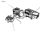
FIG. 2A is an exploded view of a bill validator and bulk feeder module with a removable cartridge. -
FIG. 2B illustrates a view of the bulk feeder module. -
FIG. 3 illustrates removal of an input tray and the cartridge to allow access to the document path. -
FIG. 4 is a side cut-away view illustrating various features of the bulk feeder module. -
FIG. 5 is a side cut-away view illustrating the location of optical sensors in the bulk feeder module. -
FIG. 6 shows the path of a note inserted in the bulk feeder module and transported to the acceptor unit. -
FIG. 7 shows the path of a note being returned. -
FIG. 8 is a cut-away view of the removable cartridge partly extracted from the bulk feeder module. -
FIG. 9 shows a cut-away view illustrating various features of the bulk feeder module. -
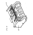
FIG. 10 is a perspective view of the removable cartridge. -
FIG. 11 shows an implementation of a banknote separator using belt and idler pulley and drive wheels. -
FIG. 12 illustrates an implementation of a banknote separator using an eccentric idler wheel. -
FIG. 13 illustrates an implementations of a banknote separator with a polygonal shaft in a polygonal bore of the idler wheel. -
FIG. 14 is a schematic of a standard bezel connector. -
FIG. 15 is a schematic of the bezel connector re-configured for use with the bulk feeder module. -
FIG. 16 is a block diagram illustrating interconnections and wiring for the bulk feeder module. - The present disclosure relates to a document handling apparatus that includes a bulk document feeder module with a removable cartridge. In some cases, the module is retrofitable to be adapted to a standard bill validator so that, with minimum change to the original validator, notes can be fed from a bundle into the validator, which then processes the notes one at a time. For example, the present disclosure facilitates adapting a bulk document feeder module to an existing MEI, Inc. Cashflow series validator unit.
- In the following description, banknotes are used as an example of documents with which the bulk feeder module can be used. The module, however, can be used with other types of documents as well, including, for example, printed coupons, intended to be processed by the acceptor module. More generally, the term "document" includes a substantially flat sheet of value including, but not limited to, banknotes, bank drafts, bills, checks, paper currency, security documents, printed coupons and other similar paper objects of value. Furthermore, a "bundle" of banknotes or other documents is not meant to imply that the banknotes or other documents are fastened together. Rather, a bundle of banknotes or other documents includes any pile of banknotes or other documents stacked one atop another.
- As illustrated in
FIGS. 1 and16 , the validator unit includes anacceptor module 3 with control means (e.g., a microprocessor) and validation means (e.g., sensors and associated circuitry), as well as a cash box (sometimes referred to as a cassette) 4 with a stacker mechanism, all of which may be installed in achassis 5. The acceptor module is coupled to a host system via an interface board (seeFIG. 16 ). - In a typical installation of the retail industry, for example, a validator unit often is installed in a safe, and bills are inserted one-by-one through a bezel (not shown) attached to the door that leads the bill to the validator unit. The safe includes a host system that manages the operation of the safe to which the bill validator is connected. The safe is a generally secure enclosure that includes a secure access door and may contain several bill acceptors with or without a bulk feeder (described below).
- One aspect of the disclosure addresses replacing the standard bezel for the validator unit with a tray that facilitates feeding a bulk of banknotes into the validator unit one note at a time. As shown in the example of
FIG. 1 , atray 6 replaces the standard bezel attached to thedoor 1 of the safe, and a bulk feeder module 7 (seeFIG. 2B ) is mounted behind the door, between the original validator unit and the door. When installed, thebulk feeder module 7 is connected to the standard bezel connector and the validator unit mechanically and electrically. - Another aspect of the disclosure addresses removal of jammed bills by providing a removable portion of the bill path in the form of a cartridge 8 (see
FIG. 2A ) that comprises part of the transport mechanism of thebulk feeder module 7. Thecartridge 8 can be made sufficiently small that it can be removed through asmall opening 11 of thedoor 1 or a wall of a safe (seeFIG. 3 ), while maintaining the cash stored in thecash box 4 secured within the safe, without having to open the door of the safe. Preferably, theopening 11 is smaller than the validator unit or theacceptor module 3 so that they cannot be removed from the safe through the opening. Removal of the cartridge allows a jammed document to be cleared by an operator who does not have the authority to open the door to the safe. This can provide an improvement over some known implementations in which the door of the safe has to be opened and the entire validator section has to be extracted in order to clear a jammed bill. Such implementations present risks of easier access to cash stored in the cash box and requires an employee with greater privileges (i.e., greater authority) than most users. - As illustrated in
FIG. 4 , theinput tray 6 has two levels that define two bins. In the illustrated example, thelower bin 12 is for an input bundle of notes and theupper bin 13 is for rejected notes. The notes are manually deposited in, or withdrawn from, the appropriate bin by an operator such as a cashier. A rotatable protective cover can be included over theupper bin 13 to reduce the likelihood of removal of notes by unauthorized persons. - The
bulk feeder module 7 includes control means comprising a microprocessor and sensors, as well as driving circuitry for a transport motor (seeFIG. 16 ), and a set of light emitting diodes (LEDs) and a buzzer to provide a human-machine interface that also includes means (e.g., keypad) for entering information. - The
bulk feeder module 7 is connected to theacceptor module 3 via an electric connection that provides power to the module and a serial communication link (RS232) coupled to the processor in the acceptor module. The synchronized operation of the bulk feeder with the validator unit is achieved via a communication protocol between the control means (e.g., microprocessor) in thebulk feeder module 7 and control means (e.g., microprocessor) of the acceptor module. - Next, the operation sequence for the bulk feeder module and validator unit according to a particular implementation is described. The
acceptor module 3, serving as the master unit, transmits commands to thebulk note feeder 7, and the bulk note feeder (serving as the slave unit) responds. Thebulk note feeder 7 includes a processor for communicating with the acceptor module, for monitoring its sensors, and for controlling its motor. The motor in the bulknote feeder module 7 has a tachometric wheel for monitoring the distance a note travels. - As shown in
FIG. 5 , thebulk note feeder 7 has three sensors: a first (bunch)sensor 20 for detecting the presence of a bundle of notes, a second (reject)sensor 21 for detecting the progress of a note being rejected (returned), and a third (progress)sensor 22 for monitoring the transport of a note through the bulk note feeder. Thesensors bulk feeder module 7. Thereject sensor 21, in combination with thestart sensor 20, also is used to detect the presence or absence of thecartridge 8. - The sensors can be implemented, for example, as optical sensors using prisms and light pipes, light sources and corresponding detectors. The general mode of operation of the sensors is based upon continuity of an optical path that is disrupted when the
cartridge 8 is removed or when a document intersects the optical beam. The sensors are operated under control of the processor in the control means of thefeeder module 7, and their status is communicated to the control means of theacceptor unit 3 upon request from the acceptor unit's control means. - In addition to issuing commands, the
acceptor module 3 continuously polls thebulk note feeder 7 to retrieve the status of thevarious sensors - The bulk
note feeder module 7 has at least the following two operating modes: an accept document mode and a reject document mode. - The process of accepting a document begins when a bundle of notes is inserted into, or placed on, the
input bin 12 oftray 6. Theacceptor module 3 communicates with thebulk note feeder 7 and, through a polling process of the sensors, detects that thebunch sensor 20 has been activated. When that happens, theacceptor module 3 starts its transport motor and commands thebulk note feeder 7 to turn on its motor. This causes a note to be stripped from the bundle in thetray 6 and fed through thebulk note feeder 7 into theacceptor module 3. Any subsequent note is prevented from moving past the acceptor module's start sensor (that is, a subsequent note is prevented from entering the acceptor module) by turning off the bulk note feeder's motor. The stripped note continues to travel through theacceptor module 3, which checks and determines the note's denomination and authenticity, and is transported to the acceptor module's escrow position where it is processed and then accepted for movement into thecassette 4 or returned via the bulk note feeder's reject path according to a command from the host system. If the note is accepted and additional notes are present in thebulk note feeder 7, then theacceptor module 3 turns on its transport motor and commands thebulk note feeder 7 to turn on its motor. A note staged at the acceptor module's start sensor is brought into the acceptor module; at that time, any subsequent notes are prevented from entering the acceptor module.FIG. 6 shows the path of the note inserted in thebulk feeder 7 going to theacceptor unit 3. - The
bulk feeder 7 includes a passive diverter 15 (seeFIGS. 4 ,9 and10 ) to direct rejected notes to thereject bin 13 of the input/output tray 6. The diverter can be active or tensioned. When at rest, thediverter 15 is in a reject position, and is lifted by an incoming note to configure the document path to feed the note to theacceptor unit 3. Thediverter 15 returns to the rest position by gravity once the note has cleared the location. Thediverter 15 is attached to theremovable cartridge 8. When a note is rejected, it is returned back through the entry slot of theacceptor module 3, and thediverter 15 configures the document path to return the note to thereject bin 13.FIG. 7 shows the path of a rejected note being returned. - When a note is rejected by the validator (e.g., because it is not recognized as an authentic note) and is to be returned, the
acceptor module 3 commands thebulk note feeder 7 to turn on its motor in reverse for a short distance or until theprogress sensor 22 becomes clear. This ensures that any note in thebulk note feeder 7 has moved back away from thediverter gate 15. This allows thediverter gate 15 to drop, thereby opening the bulk note feeder's reject path. Theacceptor module 3 then turns on its transport motor in reverse and commands thebulk note feeder 7 to turn on its own motor in reverse so that the note is returned via the bulk note feeder's reject path. The bulk note feeder'sreject sensor 21 is used to monitor the progress of the rejected note. - Next, the mechanical operation of the bulk
note feeder module 7 is described. A bundle of notes is deposited in theinput bin 12 of thetray 6, for example, with the short edge of the notes facing toward validator unit. Thetray 6 is removably attached to the safe or to the bulk feeder itself 7 through theopening 11 in the safe. The bulknote feeder module 7 includes a document transport mechanism. In the illustrated example, one end of the bundle of notes is lifted against afeeder pulley 19 by a feeder pinch arm 14 (seeFIG. 4 ). Thefeeder pinch arm 14 applies pressure when notes are inserted into thetray 6 and retracts when themodule 7 is in the note reject mode and when the input tray is emptied. Thefeeder pulley 19 pulls the banknote on top of the stack using friction. At this stage, it is possible that multiple notes are stuck together and are pulled into themodule 7. The note(s) is fed between a high friction drivepulley 18 and one ormore stripper belts 17. The stripper belts are tensioned by abelt tensioner 16 which prevents any other notes from sticking to the top banknote. Thehigh friction pulley 18 maximizes the traction on the top note while thebelts 17 act like a band brake resisting the movement with lower friction on the opposite side of the document. The friction differential allows multiple notes to be separated while allowing the top note to move forward along the transport path. As the top note continues along the document path (seeFIG. 6 ), the diverter gate 15 (FIGS. 4 ,9 and10 ) is lifted, and the note then is transported to theacceptor module 3. - In some implementations, the banknote separator includes two drive points on a drum-like arrangement. One such drive point is shown in
FIG. 11 . Thebelt 17 is either stationary and under tension, as in the preferred implementation, or may be driven backwards in an alternate implementation. Thefeeder pulley 19 intermittently or continuously pushes the bundle into the high friction wheel and belt interface. The higher friction of thedrive wheel 18 relative to the friction of thebelt 17 allows the drive wheel to drive a document around the drum. The friction of thebelt 17 in relation to the friction of the documents allows the belt to prevent forward movement of any additional documents that are in contact with the belt when a previous document is currently occupying the drive wheel. Anidler wheel 18A, or sleeve, keeps thebelt 17 relatively tangent to thedrive wheels 18 in order to provide a good pinch point for drawing the documents in. - In one implementation of the claimed invention (
FIG. 12 ), theidler wheel 25 is mounted on an eccentric section of the drum arrangement. This causes thebelt 17 to vibrate the bundle and eases the separation of sticky banknotes. - In alternative implementation of the claimed invention (
FIG. 13 ), the vibration of theidler wheel 25 and thebelt 17 is achieved by a non-circular, substantially polygonal-like shaft spinning in a non-circular, substantially polygonal-like sleeve on the idler wheel. When no note is at the belt/wheel interface, theidler wheel 25 is maintained idle by the friction of thebelt 17. When a note is sufficiently engaged between thebelt 17 and theidler wheel 25, the idler wheel spins with the shaft. - The
bulk note feeder 7 also includes circuitry to produce an audible alarm and includes a green (or other color) LED that, under control of theacceptor module 3, indicate various conditions of the system. Such conditions include whether or not the system is enabled, whether or not the cassette or cartridge is installed, whether a fault was detected, or whether a banknote jam exists. - Preferably, the
tray 6 is installed into openings in the door orouter wall 1 of the safe (seeFIG. 3 ) because it allows easy access to other elements of the system such as thecartridge 8 and provides easy access to clear a jam and to perform other maintenance service in the bulk note feeder module without opening the safe. In that case, it is desirable to provide openings large enough to insert a banknote, but not too large to prevent unauthorized access to cash through these openings. In other implementations, the tray can be connected to apertures located in a wall inside of the safe other than the door or outside walls or an aperture in a bracket connected to the bulk note feeder module. - Next, the electrical and mechanical connection of the bulk
note feeder module 7 to a validator unit is described. A standard note acceptor unit may include a connector designed to provide power and control lines to an active bezel that includes, for example, flashing LEDs. A pin allocation of an MEI Cashflow SC66/83 bill validator unit is illustrated inFIG. 14 . The four lines labeled OEM_BEZEL_n can be reconfigured for the bulknote feeder module 7 as illustrated inFIG. 15 . Thus, pins 1 and 2 can be used to provide power, and pins 3 and 4 can be used for transmitting and receiving data (TXD and RXD) of a universal asynchronous receiver/transmitter (UART) for the serial communication between thebulk feeder 7 and theacceptor module 3. - Once the bulk
note feeder module 7 is installed, theacceptor module 3 auto-detects the presence of the bulk note feeder. For example, in a particular implementation, when the bulk banknote feeder is powered up, it periodically transmits a synchronization character to the bill validator unit. When the bill validator unit detects the character, it completes the synchronization process, and communication between the two devices begins. If thebulk note feeder 7 is not attached to theacceptor module 3, the acceptor module operates as a standard bill acceptor. Theacceptor module 3 preferably maintains a copy of the bulk note feeder's processor code. When a bulknote feeder module 7 is detected, theacceptor module 3 verifies the processor's code for controlling the module and, if necessary, replaces it by downloading program code for the feeder module to memory in themodule 7. - The
bulk note feeder 7 can be retrofitted in the field by replacing the system harness that connects the bill validator to the host system. The new harness routes the communication signals and power lines to the front bezel connector, as illustrated inFIG. 16 . Thebulk note feeder 7 can be attached to theacceptor module 3 using twoscrews 9 or other mounting means (seeFIG. 2 ). Thecommunications cable 23 is attached between the acceptor module's front bezel connector and the bulk note feeder (seeFIG. 5 ). The connection to the bezel connector, located at the front of theacceptor module 3, is convenient because of its proximity to thebulk note feeder 7, which implies a relatively short connection. Alternatively, as is apparent fromFIG. 16 , thebulk note feeder 7 can be connected at the rear of theacceptor module 3 or at the rear of the interface module.
Removing thecartridge 8 from the bulk note feeder 7 (seeFIGS. 2 ,3 and8 ) allows access to the bulk note feeder's note path for purposes of clearing any jammed notes. Thus, for example, if a note becomes jammed in thefeeder module 7, the input/output tray 6 is removed from thedoor 1 of the safe, and thecartridge 8 is detached and withdrawn from thefeeder module 7 through thesmall opening 11 in the door or wall of the safe (seeFIG. 3 ). The jammed object can be cleared from the bulk document feeder module, and the cartridge and the input tray are re-installed in place in a reversed sequence.
Claims (3)
- An apparatus comprising a bulk document feeder module (7) that includes a document separator having a tensioned belt (17) operable to contact an idler wheel (25) when no document is present and having a high-friction wheel, wherein friction of the high-friction wheel on one side of a document is higher than the friction of the belt (17) on the other side of the document when a document is present between the belt and the wheel, and a processor to communicate with a document acceptor,
characterized in that the idler wheel (25) is operable to serve as a sleeve on an eccentric shaft, or
in that the idler wheel (25) is a non-circular, substantially polygonal sleeve operable to spin about a non-circular, substantially polygonal shaft. - A method of upgrading a document validator, the method comprising attaching a bulk document feeder module (7) to the document validator, and mechanically and electrically connecting the bulk document feeder module (7) to an acceptor unit of the document validator;
further comprising replacing a harness connecting the document validator to a host system to provide power and communication lines to the bulk document feeder module (7). - The method of claim 2 comprising removing a bezel adjacent a document entry of the acceptor unit and mounting an input/output tray adjacent a document entry of the bulk document feeder module (7).
Applications Claiming Priority (2)
| Application Number | Priority Date | Filing Date | Title |
|---|---|---|---|
| US82451206P | 2006-09-05 | 2006-09-05 | |
| EP07814667A EP2070059B1 (en) | 2006-09-05 | 2007-09-04 | Bulk document feeder with removable cartridge |
Related Parent Applications (1)
| Application Number | Title | Priority Date | Filing Date |
|---|---|---|---|
| EP07814667.7 Division | 2007-09-04 |
Publications (2)
| Publication Number | Publication Date |
|---|---|
| EP2254096A1 EP2254096A1 (en) | 2010-11-24 |
| EP2254096B1 true EP2254096B1 (en) | 2012-07-25 |
Family
ID=38832953
Family Applications (2)
| Application Number | Title | Priority Date | Filing Date |
|---|---|---|---|
| EP10176133A Active EP2254096B1 (en) | 2006-09-05 | 2007-09-04 | Bulk document feeder with removable cartridge |
| EP07814667A Active EP2070059B1 (en) | 2006-09-05 | 2007-09-04 | Bulk document feeder with removable cartridge |
Family Applications After (1)
| Application Number | Title | Priority Date | Filing Date |
|---|---|---|---|
| EP07814667A Active EP2070059B1 (en) | 2006-09-05 | 2007-09-04 | Bulk document feeder with removable cartridge |
Country Status (6)
| Country | Link |
|---|---|
| US (1) | US8662490B2 (en) |
| EP (2) | EP2254096B1 (en) |
| AT (1) | ATE490524T1 (en) |
| DE (1) | DE602007010962D1 (en) |
| ES (2) | ES2391624T3 (en) |
| WO (1) | WO2008030819A1 (en) |
Families Citing this family (16)
| Publication number | Priority date | Publication date | Assignee | Title |
|---|---|---|---|---|
| DE202009016832U1 (en) | 2009-11-18 | 2010-03-04 | Mei, Inc. | Modular transport unit for a document handling device |
| CN102275765B (en) | 2011-05-06 | 2013-08-21 | 广州广电运通金融电子股份有限公司 | Flaky media binding device |
| US9390594B2 (en) * | 2011-10-03 | 2016-07-12 | Tidel Engineering, L.P. | Note validator security |
| CN103514661B (en) * | 2013-10-18 | 2015-09-02 | 上海古鳌电子科技股份有限公司 | Sorting binding all-in-one |
| WO2016138540A1 (en) * | 2015-02-27 | 2016-09-01 | Ahmed Sherif N | Recognition bezel |
| JP2016224759A (en) * | 2015-06-01 | 2016-12-28 | 沖電気工業株式会社 | Media arrangement device |
| GB2575248B (en) | 2018-06-28 | 2020-09-02 | Innovative Tech Ltd | A banknote acceptor feeder device |
| USD1019785S1 (en) | 2018-08-03 | 2024-03-26 | Aristocrat Technologies, Inc. | Gaming machine |
| USD917621S1 (en) | 2018-08-03 | 2021-04-27 | Aristocrat Technologies Australia Pty Limited | Gaming machine |
| US11195369B2 (en) | 2020-05-05 | 2021-12-07 | Aristocrat Technologies, Inc. | Electronic gaming machine with access door |
| US11587389B2 (en) | 2020-09-24 | 2023-02-21 | Aristocrat Technologies, Inc. | Lift assembly and mount for a monitor of an electronic gaming machine |
| USD1040551S1 (en) | 2021-03-18 | 2024-09-03 | Aristocrat Technologies, Inc. | Gaming machine bench |
| US11995938B2 (en) | 2021-07-29 | 2024-05-28 | Aristocrat Technologies, Inc. (ATI) | Bill validator mount for electronic gaming machines |
| US11833436B2 (en) | 2021-09-30 | 2023-12-05 | Aristocrat Technologies, Inc. | Door locking assembly for a button deck of an electronic gaming machine |
| EP4427207A4 (en) * | 2021-11-05 | 2025-09-03 | Crane Payment Innovations Inc | Banknote feeder dust removal mechanism |
| JP2025169550A (en) * | 2024-05-01 | 2025-11-14 | 日本金銭機械株式会社 | Paper sheet separating and conveying device, and paper sheet handling device |
Family Cites Families (34)
| Publication number | Priority date | Publication date | Assignee | Title |
|---|---|---|---|---|
| US806650A (en) * | 1904-10-15 | 1905-12-05 | Int Harvester Co | Feeding mechanism for flax-brakes. |
| US3926201A (en) * | 1972-11-17 | 1975-12-16 | Harry Selig Katz | Method of making a disposable dental floss tooth pick |
| JPS5949682A (en) | 1982-09-16 | 1984-03-22 | 株式会社東芝 | Sectional integration apparatus |
| US4500084A (en) * | 1983-07-27 | 1985-02-19 | Technitrol, Inc. | Stripper mechanism for document separating apparatus |
| KR940011424B1 (en) | 1985-06-17 | 1994-12-15 | 가부시기가이샤 히다찌세이사꾸쇼 | Paper bills handling device and method |
| US4889220A (en) | 1986-08-06 | 1989-12-26 | Oki Electric Industry Co., Ltd. | Automatic money depositing apparatus |
| JPS63177289A (en) | 1987-01-19 | 1988-07-21 | 株式会社東芝 | Sheet paper processor |
| US6868954B2 (en) | 1990-02-05 | 2005-03-22 | Cummins-Allison Corp. | Method and apparatus for document processing |
| US6913130B1 (en) | 1996-02-15 | 2005-07-05 | Cummins-Allison Corp. | Method and apparatus for document processing |
| US6959800B1 (en) | 1995-12-15 | 2005-11-01 | Cummins-Allison Corp. | Method for document processing |
| US5295196A (en) | 1990-02-05 | 1994-03-15 | Cummins-Allison Corp. | Method and apparatus for currency discrimination and counting |
| US5815592A (en) | 1990-02-05 | 1998-09-29 | Cummins-Allison Corp. | Method and apparatus for discriminating and counting documents |
| US6866134B2 (en) | 1992-05-19 | 2005-03-15 | Cummins-Allison Corp. | Method and apparatus for document processing |
| US5394992A (en) | 1993-06-08 | 1995-03-07 | Brandt, Inc. | Document sorter |
| JPH0737138A (en) | 1993-07-16 | 1995-02-07 | Toshiba Corp | Money handling equipment |
| US5704491A (en) | 1995-07-21 | 1998-01-06 | Cummins-Allison Corp. | Method and apparatus for discriminating and counting documents |
| US6220419B1 (en) | 1994-03-08 | 2001-04-24 | Cummins-Allison | Method and apparatus for discriminating and counting documents |
| US5687963A (en) | 1994-11-14 | 1997-11-18 | Cummison-Allison Corp. | Method and apparatus for discriminating and counting documents |
| DE69513492T3 (en) | 1994-05-20 | 2010-12-16 | Fujitsu Ltd., Kawasaki | DEVICE FOR PROCESSING AND MANAGING SHEETS |
| US6880692B1 (en) | 1995-12-15 | 2005-04-19 | Cummins-Allison Corp. | Method and apparatus for document processing |
| US6721442B1 (en) | 1998-03-17 | 2004-04-13 | Cummins-Allison Corp. | Color scanhead and currency handling system employing the same |
| GB9906582D0 (en) * | 1999-03-22 | 1999-05-19 | Rue De Int Ltd | Sheet handling system |
| US6398000B1 (en) | 2000-02-11 | 2002-06-04 | Cummins-Allison Corp. | Currency handling system having multiple output receptacles |
| JP4266495B2 (en) | 2000-06-12 | 2009-05-20 | グローリー株式会社 | Banknote handling machine |
| CA2323377C (en) * | 2000-10-17 | 2008-04-22 | Cashcode Company Inc. | Validator with removable power interface |
| JP3916035B2 (en) | 2000-11-24 | 2007-05-16 | 日立オムロンターミナルソリューションズ株式会社 | Banknote handling equipment |
| US7516832B2 (en) | 2003-08-20 | 2009-04-14 | Ellenby Technologies, Inc. | Two door electronic safe |
| CA2357922A1 (en) * | 2001-09-28 | 2003-03-28 | Cashcode Company Inc. | Banknote loader |
| US6875259B2 (en) | 2002-02-26 | 2005-04-05 | Siemens Vdo Automotive, Inc. | Low cost combined air cleaner and resonator assembly |
| US20050116407A1 (en) | 2002-08-30 | 2005-06-02 | Fujitsu Limited | Paper sheets processor |
| DE602004015615D1 (en) | 2003-08-01 | 2008-09-18 | Cummins Allison Corp | DEVICE AND METHOD FOR PROCESSING BANKNOTES |
| ITTO20031011A1 (en) | 2003-12-16 | 2005-06-17 | Cts Electronics S R L Ora Cts Elect Ronicis Spa | EQUIPMENT FOR THE AUTOMATIC DEPOSIT OF BANKNOTES. |
| US8348043B2 (en) * | 2004-07-30 | 2013-01-08 | Fire King Security Products, Llc | Apparatus having a bill validator and a method of servicing the apparatus |
| CA2516555A1 (en) * | 2005-08-19 | 2007-02-19 | Cashcode Company Inc. | Banknote validator with banknote stack receiver |
-
2007
- 2007-09-04 ES ES10176133T patent/ES2391624T3/en active Active
- 2007-09-04 WO PCT/US2007/077549 patent/WO2008030819A1/en not_active Ceased
- 2007-09-04 DE DE602007010962T patent/DE602007010962D1/en active Active
- 2007-09-04 ES ES07814667T patent/ES2357170T3/en active Active
- 2007-09-04 AT AT07814667T patent/ATE490524T1/en not_active IP Right Cessation
- 2007-09-04 EP EP10176133A patent/EP2254096B1/en active Active
- 2007-09-04 US US12/439,916 patent/US8662490B2/en active Active
- 2007-09-04 EP EP07814667A patent/EP2070059B1/en active Active
Also Published As
| Publication number | Publication date |
|---|---|
| ES2357170T3 (en) | 2011-04-19 |
| ATE490524T1 (en) | 2010-12-15 |
| WO2008030819A1 (en) | 2008-03-13 |
| US20100289208A1 (en) | 2010-11-18 |
| ES2391624T3 (en) | 2012-11-28 |
| EP2254096A1 (en) | 2010-11-24 |
| DE602007010962D1 (en) | 2011-01-13 |
| EP2070059A1 (en) | 2009-06-17 |
| US8662490B2 (en) | 2014-03-04 |
| EP2070059B1 (en) | 2010-12-01 |
Similar Documents
| Publication | Publication Date | Title |
|---|---|---|
| EP2070059B1 (en) | Bulk document feeder with removable cartridge | |
| CN100416614C (en) | Banknote processing device | |
| JP5042559B2 (en) | Paper sheet handling equipment | |
| US20070296202A1 (en) | Document handling apparatus | |
| EP0563395A1 (en) | Coin depositor/dispenser | |
| KR20000028967A (en) | A Paper Money Paying-in and Paying-out Device | |
| AU2017261558B2 (en) | Banknote storing device and banknote handling machine | |
| CN109671210B (en) | Modular banknote apparatus | |
| KR101761483B1 (en) | Medium stacking apparatus and Financial device | |
| EP0308060A2 (en) | Method and apparatus for automatic bill handling | |
| JP2002312821A (en) | Bill reception and payment processing system | |
| JP6834248B2 (en) | Media processing equipment and media trading equipment | |
| JP3751519B2 (en) | Banknote handling equipment | |
| JPH11283074A (en) | Circulation type paper money receiving and paying machine | |
| JP2979519B2 (en) | Banknote deposit / withdrawal device | |
| JP3288252B2 (en) | Money receiving and dispensing machine | |
| JP3288952B2 (en) | Coin processing machine | |
| JP3336226B2 (en) | Coin processing machine | |
| CN108475451B (en) | Paper sheet handling apparatus | |
| US20140166684A1 (en) | Selective bunch presentation | |
| JPH10307946A (en) | Paper money processor | |
| JP7827807B1 (en) | Sheet handling device and transport relay member | |
| KR200379150Y1 (en) | Device for withdrawing abnormal paper money in A.T.M. | |
| JPH0581507A (en) | Automatic bill paying device | |
| JP3359840B2 (en) | Banknote handling machine |
Legal Events
| Date | Code | Title | Description |
|---|---|---|---|
| PUAI | Public reference made under article 153(3) epc to a published international application that has entered the european phase |
Free format text: ORIGINAL CODE: 0009012 |
|
| 17P | Request for examination filed |
Effective date: 20100910 |
|
| AC | Divisional application: reference to earlier application |
Ref document number: 2070059 Country of ref document: EP Kind code of ref document: P |
|
| AK | Designated contracting states |
Kind code of ref document: A1 Designated state(s): AT BE BG CH CY CZ DE DK EE ES FI FR GB GR HU IE IS IT LI LT LU LV MC MT NL PL PT RO SE SI SK TR |
|
| AX | Request for extension of the european patent |
Extension state: AL BA HR MK RS |
|
| 17Q | First examination report despatched |
Effective date: 20110214 |
|
| GRAP | Despatch of communication of intention to grant a patent |
Free format text: ORIGINAL CODE: EPIDOSNIGR1 |
|
| RIC1 | Information provided on ipc code assigned before grant |
Ipc: G07D 11/00 20060101AFI20110826BHEP |
|
| GRAS | Grant fee paid |
Free format text: ORIGINAL CODE: EPIDOSNIGR3 |
|
| GRAA | (expected) grant |
Free format text: ORIGINAL CODE: 0009210 |
|
| AC | Divisional application: reference to earlier application |
Ref document number: 2070059 Country of ref document: EP Kind code of ref document: P |
|
| AK | Designated contracting states |
Kind code of ref document: B1 Designated state(s): AT BE BG CH CY CZ DE DK EE ES FI FR GB GR HU IE IS IT LI LT LU LV MC MT NL PL PT RO SE SI SK TR |
|
| REG | Reference to a national code |
Ref country code: GB Ref legal event code: FG4D |
|
| REG | Reference to a national code |
Ref country code: CH Ref legal event code: EP |
|
| REG | Reference to a national code |
Ref country code: AT Ref legal event code: REF Ref document number: 567971 Country of ref document: AT Kind code of ref document: T Effective date: 20120815 Ref country code: IE Ref legal event code: FG4D |
|
| REG | Reference to a national code |
Ref country code: DE Ref legal event code: R096 Ref document number: 602007024251 Country of ref document: DE Effective date: 20120913 |
|
| REG | Reference to a national code |
Ref country code: ES Ref legal event code: FG2A Ref document number: 2391624 Country of ref document: ES Kind code of ref document: T3 Effective date: 20121128 |
|
| REG | Reference to a national code |
Ref country code: NL Ref legal event code: VDEP Effective date: 20120725 |
|
| REG | Reference to a national code |
Ref country code: AT Ref legal event code: MK05 Ref document number: 567971 Country of ref document: AT Kind code of ref document: T Effective date: 20120725 |
|
| REG | Reference to a national code |
Ref country code: LT Ref legal event code: MG4D Effective date: 20120725 |
|
| PG25 | Lapsed in a contracting state [announced via postgrant information from national office to epo] |
Ref country code: LT Free format text: LAPSE BECAUSE OF FAILURE TO SUBMIT A TRANSLATION OF THE DESCRIPTION OR TO PAY THE FEE WITHIN THE PRESCRIBED TIME-LIMIT Effective date: 20120725 Ref country code: AT Free format text: LAPSE BECAUSE OF FAILURE TO SUBMIT A TRANSLATION OF THE DESCRIPTION OR TO PAY THE FEE WITHIN THE PRESCRIBED TIME-LIMIT Effective date: 20120725 Ref country code: BE Free format text: LAPSE BECAUSE OF FAILURE TO SUBMIT A TRANSLATION OF THE DESCRIPTION OR TO PAY THE FEE WITHIN THE PRESCRIBED TIME-LIMIT Effective date: 20120725 Ref country code: IS Free format text: LAPSE BECAUSE OF FAILURE TO SUBMIT A TRANSLATION OF THE DESCRIPTION OR TO PAY THE FEE WITHIN THE PRESCRIBED TIME-LIMIT Effective date: 20121125 Ref country code: FI Free format text: LAPSE BECAUSE OF FAILURE TO SUBMIT A TRANSLATION OF THE DESCRIPTION OR TO PAY THE FEE WITHIN THE PRESCRIBED TIME-LIMIT Effective date: 20120725 Ref country code: CY Free format text: LAPSE BECAUSE OF FAILURE TO SUBMIT A TRANSLATION OF THE DESCRIPTION OR TO PAY THE FEE WITHIN THE PRESCRIBED TIME-LIMIT Effective date: 20120725 |
|
| PG25 | Lapsed in a contracting state [announced via postgrant information from national office to epo] |
Ref country code: GR Free format text: LAPSE BECAUSE OF FAILURE TO SUBMIT A TRANSLATION OF THE DESCRIPTION OR TO PAY THE FEE WITHIN THE PRESCRIBED TIME-LIMIT Effective date: 20121026 Ref country code: SI Free format text: LAPSE BECAUSE OF FAILURE TO SUBMIT A TRANSLATION OF THE DESCRIPTION OR TO PAY THE FEE WITHIN THE PRESCRIBED TIME-LIMIT Effective date: 20120725 Ref country code: LV Free format text: LAPSE BECAUSE OF FAILURE TO SUBMIT A TRANSLATION OF THE DESCRIPTION OR TO PAY THE FEE WITHIN THE PRESCRIBED TIME-LIMIT Effective date: 20120725 Ref country code: PL Free format text: LAPSE BECAUSE OF FAILURE TO SUBMIT A TRANSLATION OF THE DESCRIPTION OR TO PAY THE FEE WITHIN THE PRESCRIBED TIME-LIMIT Effective date: 20120725 Ref country code: PT Free format text: LAPSE BECAUSE OF FAILURE TO SUBMIT A TRANSLATION OF THE DESCRIPTION OR TO PAY THE FEE WITHIN THE PRESCRIBED TIME-LIMIT Effective date: 20121126 Ref country code: SE Free format text: LAPSE BECAUSE OF FAILURE TO SUBMIT A TRANSLATION OF THE DESCRIPTION OR TO PAY THE FEE WITHIN THE PRESCRIBED TIME-LIMIT Effective date: 20120725 |
|
| PG25 | Lapsed in a contracting state [announced via postgrant information from national office to epo] |
Ref country code: NL Free format text: LAPSE BECAUSE OF FAILURE TO SUBMIT A TRANSLATION OF THE DESCRIPTION OR TO PAY THE FEE WITHIN THE PRESCRIBED TIME-LIMIT Effective date: 20120725 |
|
| PG25 | Lapsed in a contracting state [announced via postgrant information from national office to epo] |
Ref country code: MC Free format text: LAPSE BECAUSE OF NON-PAYMENT OF DUE FEES Effective date: 20120930 Ref country code: EE Free format text: LAPSE BECAUSE OF FAILURE TO SUBMIT A TRANSLATION OF THE DESCRIPTION OR TO PAY THE FEE WITHIN THE PRESCRIBED TIME-LIMIT Effective date: 20120725 Ref country code: CZ Free format text: LAPSE BECAUSE OF FAILURE TO SUBMIT A TRANSLATION OF THE DESCRIPTION OR TO PAY THE FEE WITHIN THE PRESCRIBED TIME-LIMIT Effective date: 20120725 Ref country code: DK Free format text: LAPSE BECAUSE OF FAILURE TO SUBMIT A TRANSLATION OF THE DESCRIPTION OR TO PAY THE FEE WITHIN THE PRESCRIBED TIME-LIMIT Effective date: 20120725 Ref country code: RO Free format text: LAPSE BECAUSE OF FAILURE TO SUBMIT A TRANSLATION OF THE DESCRIPTION OR TO PAY THE FEE WITHIN THE PRESCRIBED TIME-LIMIT Effective date: 20120725 |
|
| REG | Reference to a national code |
Ref country code: CH Ref legal event code: PL |
|
| PG25 | Lapsed in a contracting state [announced via postgrant information from national office to epo] |
Ref country code: IT Free format text: LAPSE BECAUSE OF FAILURE TO SUBMIT A TRANSLATION OF THE DESCRIPTION OR TO PAY THE FEE WITHIN THE PRESCRIBED TIME-LIMIT Effective date: 20120725 Ref country code: SK Free format text: LAPSE BECAUSE OF FAILURE TO SUBMIT A TRANSLATION OF THE DESCRIPTION OR TO PAY THE FEE WITHIN THE PRESCRIBED TIME-LIMIT Effective date: 20120725 |
|
| PLBE | No opposition filed within time limit |
Free format text: ORIGINAL CODE: 0009261 |
|
| STAA | Information on the status of an ep patent application or granted ep patent |
Free format text: STATUS: NO OPPOSITION FILED WITHIN TIME LIMIT |
|
| REG | Reference to a national code |
Ref country code: IE Ref legal event code: MM4A |
|
| 26N | No opposition filed |
Effective date: 20130426 |
|
| PG25 | Lapsed in a contracting state [announced via postgrant information from national office to epo] |
Ref country code: BG Free format text: LAPSE BECAUSE OF FAILURE TO SUBMIT A TRANSLATION OF THE DESCRIPTION OR TO PAY THE FEE WITHIN THE PRESCRIBED TIME-LIMIT Effective date: 20121025 Ref country code: IE Free format text: LAPSE BECAUSE OF NON-PAYMENT OF DUE FEES Effective date: 20120904 Ref country code: CH Free format text: LAPSE BECAUSE OF NON-PAYMENT OF DUE FEES Effective date: 20120930 Ref country code: LI Free format text: LAPSE BECAUSE OF NON-PAYMENT OF DUE FEES Effective date: 20120930 |
|
| REG | Reference to a national code |
Ref country code: DE Ref legal event code: R097 Ref document number: 602007024251 Country of ref document: DE Effective date: 20130426 |
|
| PG25 | Lapsed in a contracting state [announced via postgrant information from national office to epo] |
Ref country code: MT Free format text: LAPSE BECAUSE OF FAILURE TO SUBMIT A TRANSLATION OF THE DESCRIPTION OR TO PAY THE FEE WITHIN THE PRESCRIBED TIME-LIMIT Effective date: 20120725 |
|
| PGFP | Annual fee paid to national office [announced via postgrant information from national office to epo] |
Ref country code: FR Payment date: 20130910 Year of fee payment: 7 |
|
| PG25 | Lapsed in a contracting state [announced via postgrant information from national office to epo] |
Ref country code: TR Free format text: LAPSE BECAUSE OF FAILURE TO SUBMIT A TRANSLATION OF THE DESCRIPTION OR TO PAY THE FEE WITHIN THE PRESCRIBED TIME-LIMIT Effective date: 20120725 |
|
| PG25 | Lapsed in a contracting state [announced via postgrant information from national office to epo] |
Ref country code: LU Free format text: LAPSE BECAUSE OF NON-PAYMENT OF DUE FEES Effective date: 20120904 |
|
| PG25 | Lapsed in a contracting state [announced via postgrant information from national office to epo] |
Ref country code: HU Free format text: LAPSE BECAUSE OF FAILURE TO SUBMIT A TRANSLATION OF THE DESCRIPTION OR TO PAY THE FEE WITHIN THE PRESCRIBED TIME-LIMIT Effective date: 20070904 |
|
| REG | Reference to a national code |
Ref country code: FR Ref legal event code: ST Effective date: 20150529 |
|
| PG25 | Lapsed in a contracting state [announced via postgrant information from national office to epo] |
Ref country code: FR Free format text: LAPSE BECAUSE OF NON-PAYMENT OF DUE FEES Effective date: 20140930 |
|
| REG | Reference to a national code |
Ref country code: DE Ref legal event code: R082 Ref document number: 602007024251 Country of ref document: DE Representative=s name: PETERREINS SCHLEY PATENT- UND RECHTSANWAELTE P, DE Ref country code: DE Ref legal event code: R082 Ref document number: 602007024251 Country of ref document: DE Representative=s name: PETERREINS SCHLEY PATENT- UND RECHTSANWAELTE, DE |
|
| P01 | Opt-out of the competence of the unified patent court (upc) registered |
Effective date: 20230420 |
|
| PGFP | Annual fee paid to national office [announced via postgrant information from national office to epo] |
Ref country code: DE Payment date: 20240702 Year of fee payment: 18 |
|
| PGFP | Annual fee paid to national office [announced via postgrant information from national office to epo] |
Ref country code: GB Payment date: 20240701 Year of fee payment: 18 |
|
| PGFP | Annual fee paid to national office [announced via postgrant information from national office to epo] |
Ref country code: ES Payment date: 20241008 Year of fee payment: 18 |