EP2253886A1 - Heavy fuel-oil burning boiler system and operation method of same - Google Patents
Heavy fuel-oil burning boiler system and operation method of same Download PDFInfo
- Publication number
- EP2253886A1 EP2253886A1 EP09710705A EP09710705A EP2253886A1 EP 2253886 A1 EP2253886 A1 EP 2253886A1 EP 09710705 A EP09710705 A EP 09710705A EP 09710705 A EP09710705 A EP 09710705A EP 2253886 A1 EP2253886 A1 EP 2253886A1
- Authority
- EP
- European Patent Office
- Prior art keywords
- ash
- heavy fuel
- fired boiler
- boiler system
- electric precipitator
- Prior art date
- Legal status (The legal status is an assumption and is not a legal conclusion. Google has not performed a legal analysis and makes no representation as to the accuracy of the status listed.)
- Withdrawn
Links
- 238000000034 method Methods 0.000 title claims description 9
- 239000010763 heavy fuel oil Substances 0.000 title 1
- 239000012716 precipitator Substances 0.000 claims abstract description 37
- 239000000428 dust Substances 0.000 claims abstract description 35
- MWUXSHHQAYIFBG-UHFFFAOYSA-N Nitric oxide Chemical compound O=[N] MWUXSHHQAYIFBG-UHFFFAOYSA-N 0.000 claims abstract description 24
- 239000007789 gas Substances 0.000 claims abstract description 24
- QGZKDVFQNNGYKY-UHFFFAOYSA-N Ammonia Chemical compound N QGZKDVFQNNGYKY-UHFFFAOYSA-N 0.000 claims abstract description 15
- 238000006477 desulfuration reaction Methods 0.000 claims abstract description 10
- 230000023556 desulfurization Effects 0.000 claims abstract description 10
- 229910021529 ammonia Inorganic materials 0.000 claims abstract description 6
- TXKMVPPZCYKFAC-UHFFFAOYSA-N disulfur monoxide Inorganic materials O=S=S TXKMVPPZCYKFAC-UHFFFAOYSA-N 0.000 claims abstract description 4
- 238000011084 recovery Methods 0.000 claims abstract description 4
- XTQHKBHJIVJGKJ-UHFFFAOYSA-N sulfur monoxide Chemical compound S=O XTQHKBHJIVJGKJ-UHFFFAOYSA-N 0.000 claims abstract description 4
- 239000002956 ash Substances 0.000 claims description 68
- 239000000446 fuel Substances 0.000 claims description 26
- 239000010883 coal ash Substances 0.000 claims description 23
- 238000011017 operating method Methods 0.000 claims description 16
- 239000000203 mixture Substances 0.000 claims description 12
- 238000011144 upstream manufacturing Methods 0.000 claims description 7
- 239000007788 liquid Substances 0.000 claims description 2
- 230000008021 deposition Effects 0.000 description 22
- 239000010881 fly ash Substances 0.000 description 12
- 230000003247 decreasing effect Effects 0.000 description 9
- 238000010586 diagram Methods 0.000 description 8
- 230000005484 gravity Effects 0.000 description 6
- BFNBIHQBYMNNAN-UHFFFAOYSA-N ammonium sulfate Chemical compound N.N.OS(O)(=O)=O BFNBIHQBYMNNAN-UHFFFAOYSA-N 0.000 description 5
- 229910052921 ammonium sulfate Inorganic materials 0.000 description 5
- 239000000843 powder Substances 0.000 description 5
- 235000011130 ammonium sulphate Nutrition 0.000 description 4
- 230000007423 decrease Effects 0.000 description 4
- 239000003209 petroleum derivative Substances 0.000 description 3
- 239000007787 solid Substances 0.000 description 3
- 230000002776 aggregation Effects 0.000 description 2
- 238000004220 aggregation Methods 0.000 description 2
- 150000001875 compounds Chemical class 0.000 description 2
- 238000009833 condensation Methods 0.000 description 2
- 230000005494 condensation Effects 0.000 description 2
- 230000000694 effects Effects 0.000 description 2
- 230000008018 melting Effects 0.000 description 2
- 238000002844 melting Methods 0.000 description 2
- 229910000069 nitrogen hydride Inorganic materials 0.000 description 2
- 229910052720 vanadium Inorganic materials 0.000 description 2
- LEONUFNNVUYDNQ-UHFFFAOYSA-N vanadium atom Chemical compound [V] LEONUFNNVUYDNQ-UHFFFAOYSA-N 0.000 description 2
- 239000002028 Biomass Substances 0.000 description 1
- OKTJSMMVPCPJKN-UHFFFAOYSA-N Carbon Chemical compound [C] OKTJSMMVPCPJKN-UHFFFAOYSA-N 0.000 description 1
- 238000010521 absorption reaction Methods 0.000 description 1
- 230000002378 acidificating effect Effects 0.000 description 1
- 239000000654 additive Substances 0.000 description 1
- 230000000996 additive effect Effects 0.000 description 1
- 239000003990 capacitor Substances 0.000 description 1
- 229910052799 carbon Inorganic materials 0.000 description 1
- 230000015556 catabolic process Effects 0.000 description 1
- 238000006243 chemical reaction Methods 0.000 description 1
- 238000004140 cleaning Methods 0.000 description 1
- 239000003245 coal Substances 0.000 description 1
- 238000002485 combustion reaction Methods 0.000 description 1
- 239000000470 constituent Substances 0.000 description 1
- 238000005260 corrosion Methods 0.000 description 1
- 230000007797 corrosion Effects 0.000 description 1
- 238000006731 degradation reaction Methods 0.000 description 1
- 239000000295 fuel oil Substances 0.000 description 1
- 238000002347 injection Methods 0.000 description 1
- 239000007924 injection Substances 0.000 description 1
- 239000003921 oil Substances 0.000 description 1
- 239000002245 particle Substances 0.000 description 1
- 239000002006 petroleum coke Substances 0.000 description 1
- 239000011301 petroleum pitch Substances 0.000 description 1
- 238000010248 power generation Methods 0.000 description 1
Images



Classifications
-
- F—MECHANICAL ENGINEERING; LIGHTING; HEATING; WEAPONS; BLASTING
- F23—COMBUSTION APPARATUS; COMBUSTION PROCESSES
- F23J—REMOVAL OR TREATMENT OF COMBUSTION PRODUCTS OR COMBUSTION RESIDUES; FLUES
- F23J15/00—Arrangements of devices for treating smoke or fumes
- F23J15/003—Arrangements of devices for treating smoke or fumes for supplying chemicals to fumes, e.g. using injection devices
-
- F—MECHANICAL ENGINEERING; LIGHTING; HEATING; WEAPONS; BLASTING
- F23—COMBUSTION APPARATUS; COMBUSTION PROCESSES
- F23J—REMOVAL OR TREATMENT OF COMBUSTION PRODUCTS OR COMBUSTION RESIDUES; FLUES
- F23J15/00—Arrangements of devices for treating smoke or fumes
- F23J15/02—Arrangements of devices for treating smoke or fumes of purifiers, e.g. for removing noxious material
-
- F—MECHANICAL ENGINEERING; LIGHTING; HEATING; WEAPONS; BLASTING
- F23—COMBUSTION APPARATUS; COMBUSTION PROCESSES
- F23J—REMOVAL OR TREATMENT OF COMBUSTION PRODUCTS OR COMBUSTION RESIDUES; FLUES
- F23J15/00—Arrangements of devices for treating smoke or fumes
- F23J15/06—Arrangements of devices for treating smoke or fumes of coolers
-
- F—MECHANICAL ENGINEERING; LIGHTING; HEATING; WEAPONS; BLASTING
- F23—COMBUSTION APPARATUS; COMBUSTION PROCESSES
- F23J—REMOVAL OR TREATMENT OF COMBUSTION PRODUCTS OR COMBUSTION RESIDUES; FLUES
- F23J2215/00—Preventing emissions
- F23J2215/10—Nitrogen; Compounds thereof
- F23J2215/101—Nitrous oxide (N2O)
-
- F—MECHANICAL ENGINEERING; LIGHTING; HEATING; WEAPONS; BLASTING
- F23—COMBUSTION APPARATUS; COMBUSTION PROCESSES
- F23J—REMOVAL OR TREATMENT OF COMBUSTION PRODUCTS OR COMBUSTION RESIDUES; FLUES
- F23J2215/00—Preventing emissions
- F23J2215/20—Sulfur; Compounds thereof
-
- F—MECHANICAL ENGINEERING; LIGHTING; HEATING; WEAPONS; BLASTING
- F23—COMBUSTION APPARATUS; COMBUSTION PROCESSES
- F23J—REMOVAL OR TREATMENT OF COMBUSTION PRODUCTS OR COMBUSTION RESIDUES; FLUES
- F23J2217/00—Intercepting solids
- F23J2217/10—Intercepting solids by filters
- F23J2217/102—Intercepting solids by filters electrostatic
-
- Y—GENERAL TAGGING OF NEW TECHNOLOGICAL DEVELOPMENTS; GENERAL TAGGING OF CROSS-SECTIONAL TECHNOLOGIES SPANNING OVER SEVERAL SECTIONS OF THE IPC; TECHNICAL SUBJECTS COVERED BY FORMER USPC CROSS-REFERENCE ART COLLECTIONS [XRACs] AND DIGESTS
- Y02—TECHNOLOGIES OR APPLICATIONS FOR MITIGATION OR ADAPTATION AGAINST CLIMATE CHANGE
- Y02E—REDUCTION OF GREENHOUSE GAS [GHG] EMISSIONS, RELATED TO ENERGY GENERATION, TRANSMISSION OR DISTRIBUTION
- Y02E20/00—Combustion technologies with mitigation potential
- Y02E20/30—Technologies for a more efficient combustion or heat usage
Definitions
- the present invention relates to a heavy fuel-fired boiler system that decreases ash deposition even when low-grade fuel such as heavy oil is used, and an operating method thereof.
- Patent Documents 1 and 2 An additive such as MgO is added to the petroleum residue.
- An additive such as MgO is added to the petroleum residue.
- Patent Documents 1 and 2 a measure against ash deposition has been taken with respect to a biomass fuel by co-combustion with coal.
- an air feed rate is controlled appropriately in accordance with a set value of O 2 concentration at an outlet of the boiler so that there is no risk of accidental fire in the boiler.
- a vacuum residual oil (VR) vacuum residual oil
- the heavy fuel-fired boiler using, for example, a vacuum residual oil (VR), petroleum coke, or pitch, there can be troubles due to deposition of generated fly ash on a downstream device. Then, stable driving is impeded, a huge operating loss is generated in power generation, and a cleaning expense accrues. Accordingly, there has been a strong demand for development of a control method of ash deposition.
- the amount of fly ash to the downstream side can be decreased by increasing charge to the electric precipitator.
- concentration of the unburned C in the fly ash decreases as a result. This causes to change the fly ash composition (unburned C concentration/S concentration ratio), and increase ash deposition, which can lead to troubles due to the ash deposition (for example, an IDF vibration trouble).
- an object of the present invention is to provide a heavy fuel-fired boiler system that can reduce ash deposition at the time of performing a burning process using low-grade fuel, and to provide an operating method thereof.
- a first invention according to the present invention is a heavy fuel-fired boiler system including a denitration device that removes nitrogen oxide in exhaust gas from a heavy fuel-fired boiler, an air preheater that recovers heat in the gas after the nitrogen oxide is removed, an electric precipitator that removes dust while adding ammonia into the gas after heat recovery, a vapor-liquid contact type desulfurization device that removes sulfur oxide in the gas after dust removal, and a stack that exhausts the gas after desulfurization to outside.
- the heavy fuel-fired boiler system includes an ash flowability measuring instrument that measures flowability of ash on a downstream side of the electric precipitator.
- the heavy fuel-fired boiler system adjusts a feed rate of an air supply unit that supplies air to a boiler according to ash flowability information.
- a second invention based on the first invention is a heavy fuel-fired boiler system, in which the ash flowability measuring instrument is an ash shear-force measuring instrument.
- a third invention based on one of the first and the second invention is a heavy fuel-fired boiler system, in which an air feed rate is adjusted according to a fuel composition of a heavy fuel.
- a fourth invention based on any one of the first to the third invention is a heavy fuel-fired boiler system which includes a dust densitometer that measures dust concentration on a downstream side of the electric precipitator for adjusting the air feed rate according to a dust amount.
- a fifth invention based on the first invention is a heavy fuel-fired boiler system which further includes a coal-ash supply unit that supplies coal ash on an upstream side of the electric precipitator for supplying the coal ash according to a dust amount.
- a sixth invention is an operating method of a heavy fuel-fired boiler system including a boiler using a heavy fuel, and the method includes measuring ash flowability on a downstream side of an electric precipitator that removes dust in exhaust gas, and adjusting an air feed rate to the boiler by ash flowability information.
- a seventh invention based on the sixth invention is an operating method of a heavy fuel-fired boiler system, in which the ash flowability information is ash shear-force information.
- An eighth invention based on one of the sixth and the seventh inventions is an operating method of a heavy fuel-fired boiler system, in which an air feed rate is adjusted according to a fuel composition of a heavy fuel.
- a ninth invention based on any one of the sixth to the eighth inventions is an operating method of a heavy fuel-fired boiler system, in which dust concentration is measured on a downstream side of the electric precipitator, and an air feed rate is adjusted according to a dust amount.
- a tenth invention based on the sixth invention is an operating method of a heavy fuel-fired boiler system, in which a coal-ash supply unit is arranged on an upstream side of the electric precipitator to supply coal ash, and the coal ash is supplied according to a dust amount.
- the fly ash composition (unburned C concentration/S concentration ratio) is constant regardless of fuel properties, and troubles due to ash deposition can be prevented.
- a first heavy fuel-fired boiler system 10-1 is an exhaust gas treatment system including a denitration device 12 that removes nitrogen oxide in exhaust gas from a heavy fuel-fired boiler 11, an air preheater 13 that recovers heat in the gas after the nitrogen oxide is removed, an electric precipitator 15 that removes dust while adding ammonia (NH 3 ) 14 into the gas after heat recovery, a desulfurization device 17 that removes sulfur oxide in the gas after dust removal, and a stack 18 that exhausts the gas after desulfurization to the outside, where an ash-shear-force measuring instrument 20 that measures an ash shear force, in other words, flowability of the ash, on the downstream side of the electric precipitator 15 is provided so that a feed rate of an ash-shear-force measuring instrument 20 that measures an ash shear force, in other words, flowability of the ash, on the downstream side of the electric precipitator 15 is provided so that a feed rate of an ash-shear-force measuring instrument 20 that measures an ash shear force
- the ash-shear-force measuring instrument 20 obtains information of a shear force in the ash, and the ash shear-force information X 1 is consolidated by a central operation control system (CPU) 21.
- An air control command Y 1 is issued to the air supply unit 23 so that an appropriate air feed rate to the boiler 11 is calculated based on the ash shear-force information X 1 to control the air feed rate to the boiler 11.
- Fig. 5 depicts a relation between unburned C concentration and an ash shear force
- Fig. 6 depicts a relation between C/SO 3 (molar ratio) and an ash shear force.
- a predetermined threshold for example, 5 gf/cm 2 or higher in Fig. 5
- the CPU 21 issues the air control command Y 1 to the air supply unit 23 to increase the unburned C concentration.
- the target ash when the ash shear force is measured, the target ash is filled in a measuring cell.
- the measuring cell is shifted to the side to measure the shear force in a shear plane. Adhesion and a frictional force between particles in a powder layer are evaluated based on the measured shear force.
- the unburned C content is increased, and as a result, the unburned C concentration in the fly ash is increased, the unburned C concentration in the ash is increased with respect to the S content, and ash deposition is decreased, thereby allowing to prevent a trouble due to ash deposition (for example, an IDF vibration trouble).
- the air content is controlled based on the ash shear force as the ash flowability information.
- the present invention is not limited thereto, and the air feed rate can be adjusted by obtaining parameters such as "loose apparent specific gravity”, “solid apparent specific gravity”, “condensation”, “aggregation”, “spatula angle”, and “angle of repose” of the ash by, for example, a powder tester or the like that measures physical characteristics of the ash.
- the condensation is obtained from the loose apparent specific gravity and the solid apparent specific gravity.
- the aggregation is obtained from a weight ratio of powder remained in sieves when a plurality of types of sieves is selected according to a mean value of the loose apparent specific gravity and the solid apparent specific gravity and vibrated.
- the spatula angle is a laterally-inclined angle of the powder remained on a spatula when the spatula is lifted up after the ash is piled up on the spatula.
- the angle of repose is an angle of a ridge line of the powder deposited by a natural drop.
- FIG. 2 is a schematic configuration diagram of a second heavy fuel-fired boiler system according to the second embodiment.
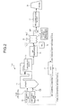
- a second heavy fuel-fired boiler system 10-2 issues an air control command Y 2 for adjusting an air content A supplied from the air supply unit 23 by the CPU 21 based on fuel composition information X 2 of the fuel supplied from a fuel supply unit 22.
- the unburned C content is increased, and as a result, the unburned C concentration in the fly ash is increased, the unburned C concentration in the ash is increased with respect to the S content, and ash deposition is decreased, thereby allowing to prevent a trouble due to ash deposition (for example, an IDF vibration trouble).
- Fig. 3 is a schematic configuration diagram of a third heavy fuel-fired boiler system according to the third embodiment.
- a third heavy fuel-fired boiler system 10-3 according to the present embodiment includes a dust densitometer 24 that measures dust concentration on the downstream side of the electric precipitator 15 configured as in the boiler system 10-1 according to the first embodiment, to adjust the air feed rate according to the dust amount.
- the dust densitometer 24 obtains a fly ash amount on the downstream side of the electric precipitator 15, other than the ash flowability information and the heavy fuel composition information.
- the obtained dust concentration information (information of fly ash amount) X 3 is consolidated by the central operation control system (CPU) 21.
- An air control command Y 3 is issued to the air supply unit 23 so that an appropriate air feed rate to the boiler 11 is calculated based on the ash shear-force information X 1 and the dust concentration information X 3 to control the air feed rate to the boiler 11.
- the third heavy fuel-fired boiler system 10-3 has a function of calculating an appropriate electric charge of the electric precipitator (EP) based on the ash shear-force information X 1 to control a dust collection amount in respective chambers (15-1, 15-2, and 15-3) of the electric precipitator 15.
- EP electric precipitator
- the ash deposition can be decreased by increasing and appropriately controlling an unburned C concentration/S concentration ratio in the fly ash at an outlet of the electric precipitator 15.
- the fly ash composition (unburned C concentration/S concentration ratio) is constant regardless of the fuel properties, and troubles due to ash deposition can be prevented.
- FIG. 4 is a schematic configuration diagram of a fourth heavy fuel-fired boiler system according to the fourth embodiment.
- a fourth heavy fuel-fired boiler system 10-4 according to the present embodiment is configured similarly to the boiler system 10-1 according to the first embodiment, and includes a coal-ash supply unit 33, to which coal ash 31 is supplied from a coal-ash receiving unit 32, on the upstream side of the electric precipitator 15, so that the coal ash 31 is supplied thereto according to the dust amount.
- ash deposition is decreased by using the coal ash 31 generated in the coal-fired power plant 30.
- the coal-ash supply unit 33 such as a hopper and a feeder receives the coal ash 31 from the outside and injects the coal ash 31 into a flue.
- An appropriate coal-ash injection volume of the coal ash 31 to be injected can be calculated from the ash deposition data.
- the central operation control system (CPU) 21 can issue a coal-ash feed-rate control command Y 4 .
- Troubles due to ash deposition can be prevented by increasing the unburned C content by combining the second and third embodiments with the present embodiment to decrease ash deposition.
- the fly ash composition (unburned C concentration/S concentration ratio) is constant regardless of the fuel properties, and troubles due to ash deposition can be prevented, thereby allowing to perform stable boiler operation for a long period of time.
Landscapes
- Engineering & Computer Science (AREA)
- Mechanical Engineering (AREA)
- General Engineering & Computer Science (AREA)
- Chemical & Material Sciences (AREA)
- Chemical Kinetics & Catalysis (AREA)
- General Chemical & Material Sciences (AREA)
- Regulation And Control Of Combustion (AREA)
- Chimneys And Flues (AREA)
- Treating Waste Gases (AREA)
Abstract
Description
- The present invention relates to a heavy fuel-fired boiler system that decreases ash deposition even when low-grade fuel such as heavy oil is used, and an operating method thereof.
- Conventionally, it is well-known that when, for example, a petroleum residue is used as low-grade fuel, vanadium in the petroleum residue fuel generates a low melting compound, and the low melting compound exhibits a binding effect to cause an ash deposition phenomenon to a heat-transfer pipe in a boiler.
- An additive such as MgO is added to the petroleum residue. On the other hand, a measure against ash deposition has been taken with respect to a biomass fuel by co-combustion with coal (Patent Documents 1 and 2).
-
- Patent Document 1: Japanese Patent Application Laid-open No.
2002-243108 - Patent Document 2: Japanese Patent Application Laid-open No.
2007-107757 - In the conventional heavy fuel-fired boiler, an air feed rate is controlled appropriately in accordance with a set value of O2 concentration at an outlet of the boiler so that there is no risk of accidental fire in the boiler. In the heavy fuel-fired boiler using, for example, a vacuum residual oil (VR), petroleum coke, or pitch, there can be troubles due to deposition of generated fly ash on a downstream device. Then, stable driving is impeded, a huge operating loss is generated in power generation, and a cleaning expense accrues. Accordingly, there has been a strong demand for development of a control method of ash deposition.
- Further, when an S content in the fuel to be used increases, acidic ammonium sulfate ((NH4)HSO4) and ammonium sulfate ((NH4)2SO4) relatively increase due to a reaction with ammonia (NH3) injected into an upstream side of an electric precipitator for preventing corrosion, thereby increasing ash deposition. As a result, deposit to the downstream device (the electric precipitator and an induced draft fan (IDF)) increases, and a trouble of insufficient removal of hopper ash from the electric precipitator or a trouble of increasing vibrations of the IDF can occur.
Further, even if there is no change in the S content in the fuel, when combustibility of the fuel is improved and unburned C content in the ash decreases with respect to the S content, ash deposition increases and it can be a cause of the same troubles. - The amount of fly ash to the downstream side can be decreased by increasing charge to the electric precipitator. However, because unburned C is collected preferentially to the ammonium sulfate content, concentration of the unburned C in the fly ash decreases as a result. This causes to change the fly ash composition (unburned C concentration/S concentration ratio), and increase ash deposition, which can lead to troubles due to the ash deposition (for example, an IDF vibration trouble).
- In view of the above problems, an object of the present invention is to provide a heavy fuel-fired boiler system that can reduce ash deposition at the time of performing a burning process using low-grade fuel, and to provide an operating method thereof.
- To solve the problems as described above, a first invention according to the present invention is a heavy fuel-fired boiler system including a denitration device that removes nitrogen oxide in exhaust gas from a heavy fuel-fired boiler, an air preheater that recovers heat in the gas after the nitrogen oxide is removed, an electric precipitator that removes dust while adding ammonia into the gas after heat recovery, a vapor-liquid contact type desulfurization device that removes sulfur oxide in the gas after dust removal, and a stack that exhausts the gas after desulfurization to outside. The heavy fuel-fired boiler system includes an ash flowability measuring instrument that measures flowability of ash on a downstream side of the electric precipitator. The heavy fuel-fired boiler system adjusts a feed rate of an air supply unit that supplies air to a boiler according to ash flowability information.
- A second invention based on the first invention is a heavy fuel-fired boiler system, in which the ash flowability measuring instrument is an ash shear-force measuring instrument.
- A third invention based on one of the first and the second invention is a heavy fuel-fired boiler system, in which an air feed rate is adjusted according to a fuel composition of a heavy fuel.
- A fourth invention based on any one of the first to the third invention is a heavy fuel-fired boiler system which includes a dust densitometer that measures dust concentration on a downstream side of the electric precipitator for adjusting the air feed rate according to a dust amount.
- A fifth invention based on the first invention is a heavy fuel-fired boiler system which further includes a coal-ash supply unit that supplies coal ash on an upstream side of the electric precipitator for supplying the coal ash according to a dust amount.
- A sixth invention is an operating method of a heavy fuel-fired boiler system including a boiler using a heavy fuel, and the method includes measuring ash flowability on a downstream side of an electric precipitator that removes dust in exhaust gas, and adjusting an air feed rate to the boiler by ash flowability information.
- A seventh invention based on the sixth invention is an operating method of a heavy fuel-fired boiler system, in which the ash flowability information is ash shear-force information.
- An eighth invention based on one of the sixth and the seventh inventions is an operating method of a heavy fuel-fired boiler system, in which an air feed rate is adjusted according to a fuel composition of a heavy fuel.
- A ninth invention based on any one of the sixth to the eighth inventions is an operating method of a heavy fuel-fired boiler system, in which dust concentration is measured on a downstream side of the electric precipitator, and an air feed rate is adjusted according to a dust amount.
- A tenth invention based on the sixth invention is an operating method of a heavy fuel-fired boiler system, in which a coal-ash supply unit is arranged on an upstream side of the electric precipitator to supply coal ash, and the coal ash is supplied according to a dust amount.
- According to the present invention, the fly ash composition (unburned C concentration/S concentration ratio) is constant regardless of fuel properties, and troubles due to ash deposition can be prevented.
-
- [
Fig. 1] Fig. 1 is a schematic diagram of a heavy fuel-fired boiler system according to a first embodiment. - [
Fig. 2] Fig. 2 is a schematic diagram of a heavy fuel-fired boiler system according to a second embodiment. - [
Fig. 3] Fig. 3 is a schematic diagram of a heavy fuel-fired boiler system according to a third embodiment. - [
Fig. 4] Fig. 4 is a schematic diagram of a heavy fuel-fired boiler system according to a fourth embodiment. - [
Fig. 5] Fig. 5 depicts a relation between unburned carbon concentration and an ash shear force. - [
Fig. 6] Fig. 6 depicts a relation between C/SO3 (molar ratio) and an ash shear force. -
- 10-1 to 10-4
- first to fourth heavy fuel-fired boiler system
- 11
- heavy fuel-fired boiler
- 12
- denitration device
- 13
- air preheater
- 14
- ammonia
- 15
- electric precipitator
- 17
- desulfurization device
- 18
- stack
- 20
- ash-shear-force measuring instrument
- The present invention will be explained below in detail with reference to the accompanying drawings. The invention is not limited to the embodiments. In addition, constituent elements in the embodiments may include those that can be easily achieved by those skilled in the art or that are substantially equivalent thereto.
- A heavy fuel-fired boiler system and an operating method thereof according to a first embodiment of the present invention are explained with reference to drawings.
Fig. 1 is a schematic configuration diagram of a first heavy fuel-fired boiler system according to the first embodiment.
As shown inFig. 1 , a first heavy fuel-fired boiler system 10-1 according to the present embodiment is an exhaust gas treatment system including adenitration device 12 that removes nitrogen oxide in exhaust gas from a heavy fuel-firedboiler 11, anair preheater 13 that recovers heat in the gas after the nitrogen oxide is removed, anelectric precipitator 15 that removes dust while adding ammonia (NH3) 14 into the gas after heat recovery, adesulfurization device 17 that removes sulfur oxide in the gas after dust removal, and astack 18 that exhausts the gas after desulfurization to the outside, where an ash-shear-force measuring instrument 20 that measures an ash shear force, in other words, flowability of the ash, on the downstream side of theelectric precipitator 15 is provided so that a feed rate of anair supply unit 23 that supplies air A to the boiler is reduced according to ash shear-force information X1. - That is, the ash-shear-
force measuring instrument 20 obtains information of a shear force in the ash, and the ash shear-force information X1 is consolidated by a central operation control system (CPU) 21.
An air control command Y1 is issued to theair supply unit 23 so that an appropriate air feed rate to theboiler 11 is calculated based on the ash shear-force information X1 to control the air feed rate to theboiler 11. -
Fig. 5 depicts a relation between unburned C concentration and an ash shear force, andFig. 6 depicts a relation between C/SO3 (molar ratio) and an ash shear force.
As shown inFigs. 5 and 6 , when the unburned C concentration is low, the ash shear force increases. Therefore, when the ash shear force measured by the ash-shear-force measuring instrument 20 is equal to or higher than a predetermined threshold (for example, 5 gf/cm2 or higher inFig. 5 ), theCPU 21 issues the air control command Y1 to theair supply unit 23 to increase the unburned C concentration. - In the present embodiment, when the ash shear force is measured, the target ash is filled in a measuring cell. The measuring cell is shifted to the side to measure the shear force in a shear plane. Adhesion and a frictional force between particles in a powder layer are evaluated based on the measured shear force.
- According to the present embodiment, by decreasing the air feed rate to the boiler, the unburned C content is increased, and as a result, the unburned C concentration in the fly ash is increased, the unburned C concentration in the ash is increased with respect to the S content, and ash deposition is decreased, thereby allowing to prevent a trouble due to ash deposition (for example, an IDF vibration trouble).
- According to the present embodiment, the air content is controlled based on the ash shear force as the ash flowability information. However, the present invention is not limited thereto, and the air feed rate can be adjusted by obtaining parameters such as "loose apparent specific gravity", "solid apparent specific gravity", "condensation", "aggregation", "spatula angle", and "angle of repose" of the ash by, for example, a powder tester or the like that measures physical characteristics of the ash.
- The condensation is obtained from the loose apparent specific gravity and the solid apparent specific gravity.
The aggregation is obtained from a weight ratio of powder remained in sieves when a plurality of types of sieves is selected according to a mean value of the loose apparent specific gravity and the solid apparent specific gravity and vibrated.
The spatula angle is a laterally-inclined angle of the powder remained on a spatula when the spatula is lifted up after the ash is piled up on the spatula.
The angle of repose is an angle of a ridge line of the powder deposited by a natural drop. - A heavy fuel-fired boiler system and an operating method thereof according to a second embodiment of the present invention are explained with reference to the drawing.
Fig. 2 is a schematic configuration diagram of a second heavy fuel-fired boiler system according to the second embodiment.
As shown inFig. 2 , based on the boiler system 10-1 according to the first embodiment, a second heavy fuel-fired boiler system 10-2 according to the present embodiment issues an air control command Y2 for adjusting an air content A supplied from theair supply unit 23 by theCPU 21 based on fuel composition information X2 of the fuel supplied from afuel supply unit 22. - According to the present embodiment, by decreasing the air content to the boiler according to the composition (S content, ash content, vanadium content, composition data, and the like) of the heavy fuel in addition to the ash flowability information, the unburned C content is increased, and as a result, the unburned C concentration in the fly ash is increased, the unburned C concentration in the ash is increased with respect to the S content, and ash deposition is decreased, thereby allowing to prevent a trouble due to ash deposition (for example, an IDF vibration trouble).
- A heavy fuel-fired boiler system and an operating method thereof according to a third embodiment of the present invention are explained with reference to the drawing.
Fig. 3 is a schematic configuration diagram of a third heavy fuel-fired boiler system according to the third embodiment.
As shown inFig. 3 , a third heavy fuel-fired boiler system 10-3 according to the present embodiment includes adust densitometer 24 that measures dust concentration on the downstream side of theelectric precipitator 15 configured as in the boiler system 10-1 according to the first embodiment, to adjust the air feed rate according to the dust amount. - In the present embodiment, the
dust densitometer 24 obtains a fly ash amount on the downstream side of theelectric precipitator 15, other than the ash flowability information and the heavy fuel composition information.
The obtained dust concentration information (information of fly ash amount) X3 is consolidated by the central operation control system (CPU) 21. - An air control command Y3 is issued to the
air supply unit 23 so that an appropriate air feed rate to theboiler 11 is calculated based on the ash shear-force information X1 and the dust concentration information X3 to control the air feed rate to theboiler 11. - The third heavy fuel-fired boiler system 10-3 has a function of calculating an appropriate electric charge of the electric precipitator (EP) based on the ash shear-force information X1 to control a dust collection amount in respective chambers (15-1, 15-2, and 15-3) of the
electric precipitator 15. - As a result, the ash deposition can be decreased by increasing and appropriately controlling an unburned C concentration/S concentration ratio in the fly ash at an outlet of the
electric precipitator 15. - Specifically, by decreasing a collection amount of the unburned C in the first chamber 15-1 of the
electric precipitator 15 and introducing the unburned C into the second and third chambers 15-2 and 15-3, a trouble of insufficient removal of EP ash and a vibration trouble of the IDF can be prevented. - According to the present embodiment, the fly ash composition (unburned C concentration/S concentration ratio) is constant regardless of the fuel properties, and troubles due to ash deposition can be prevented.
- As a method of dropping a current in the
electric precipitator 15, there are mainly the following methods. - (1) Continuous charging: a method of dropping a set value of the current and charging a constant current by the set current value.
- (2) Intermittent charging: a method of dropping an average current by intermittently turning the charge ON and OFF.
- Further, adjustment of the electric charge of the
electric precipitator 15 is explained.
In the charge adjustment, it is required that a collecting performance in an upstream chamber, which is the first chamber 15-1 constituting theelectric precipitator 15, is suppressed to be low and a boiler dust that can be collected more easily than ammonium sulfate can reach the downstream chambers (second and third chambers 15-2 and 15-3).
Normally, therefore, the current in the first chamber 15-1 is dropped to about 1/2 of the rated current. At the time of this operation, it is estimated how much the total performance of theelectric precipitator 15 is degraded by dropping the electric charge in the first chamber 15-1 based on data of the dust concentration at the inlet and the outlet of theelectric precipitator 15, to drop the current within a range that degradation of the performance is below a power assurance value. For example, as a criterion for dropping the current value, 1/2, 1/3, or 1/4 of the rated current is used.
Further, if theelectric precipitator 15 has only a limited performance due to controlled electric charges, dust removal may also be performed in thedesulfurization device 17 by absorption. - A heavy fuel-fired boiler system and an operating method thereof according to a fourth embodiment of the present invention are explained with reference to the drawing.
Fig. 4 is a schematic configuration diagram of a fourth heavy fuel-fired boiler system according to the fourth embodiment.
As shown inFig. 4 , a fourth heavy fuel-fired boiler system 10-4 according to the present embodiment is configured similarly to the boiler system 10-1 according to the first embodiment, and includes a coal-ash supply unit 33, to whichcoal ash 31 is supplied from a coal-ash receiving unit 32, on the upstream side of theelectric precipitator 15, so that thecoal ash 31 is supplied thereto according to the dust amount. - In the present embodiment, when there is a coal-fired
power plant 30 in a facility, ash deposition is decreased by using thecoal ash 31 generated in the coal-firedpower plant 30.
The coal-ash supply unit 33 such as a hopper and a feeder receives thecoal ash 31 from the outside and injects thecoal ash 31 into a flue.
An appropriate coal-ash injection volume of thecoal ash 31 to be injected can be calculated from the ash deposition data. Based on a result of calculation, the central operation control system (CPU) 21 can issue a coal-ash feed-rate control command Y4. - Troubles due to ash deposition (for example, an IDF vibration trouble) can be prevented by increasing the unburned C content by combining the second and third embodiments with the present embodiment to decrease ash deposition.
- As described above, according to the heavy fuel-fired boiler system according to the present invention, the fly ash composition (unburned C concentration/S concentration ratio) is constant regardless of the fuel properties, and troubles due to ash deposition can be prevented, thereby allowing to perform stable boiler operation for a long period of time.
Further, in the case of the intermittent charging, the voltage at the time of ON is the same as that of a rated current. Accordingly, the performance is better than the case of simply dropping the current.
Claims (10)
- A heavy fuel-fired boiler system comprising:a denitration device that removes nitrogen oxide in exhaust gas from a heavy fuel-fired boiler;an air preheater that recovers heat in the gas after the nitrogen oxide is removed;an electric precipitator that removes dust while adding ammonia into the gas after heat recovery;a vapor-liquid contact type desulfurization device that removes sulfur oxide in the gas after dust removal; anda stack that exhausts the gas after desulfurization to outside, whereinthe heavy fuel-fired boiler system includes an ash flowability measuring instrument that measures flowability of ash on a downstream side of the electric precipitator, the heavy fuel-fired boiler system adjusts a feed rate of an air supply unit that supplies air to a boiler according to ash flowability information.
- The heavy fuel-fired boiler system according to claim 1, wherein the ash flowability measuring instrument is an ash shear-force measuring instrument.
- The heavy fuel-fired boiler system according to claim 1 or 2, wherein an air feed rate is adjusted according to a fuel composition of a heavy fuel.
- The heavy fuel-fired boiler system according to any one of claims 1 to 3, comprising a dust densitometer that measures dust concentration on a downstream side of the electric precipitator for adjusting the air feed rate according to a dust amount.
- The heavy fuel-fired boiler system according to claim 1, further comprising a coal-ash supply unit that supplies coal ash on an upstream side of the electric precipitator for supplying the coal ash according to a dust amount.
- An operating method of a heavy fuel-fired boiler system including a boiler using a heavy fuel, the method comprising:measuring ash flowability on a downstream side of an electric precipitator that removes dust in exhaust gas, andadjusting an air feed rate to the boiler by ash flowability information.
- The operating method of a heavy fuel-fired boiler system according to claim 6, wherein
the ash flowability information is ash shear-force information. - The operating method of a heavy fuel-fired boiler system according to claim 6 or 7, wherein an air feed rate is adjusted according to a fuel composition of a heavy fuel.
- The operating method of a heavy fuel-fired boiler system according to any one of claims 6 to 8, wherein
dust concentration is measured on a downstream side of the electric precipitator, and an air feed rate is adjusted according to a dust amount. - The operating method of a heavy fuel-fired boiler system according to claim 6, wherein
a coal-ash supply unit is arranged on an upstream side of the electric precipitator to supply coal ash, and the coal ash is supplied according to a dust amount.
Applications Claiming Priority (2)
| Application Number | Priority Date | Filing Date | Title |
|---|---|---|---|
| JP2008030721A JP4909296B2 (en) | 2008-02-12 | 2008-02-12 | Heavy fuel fired boiler system and operating method thereof |
| PCT/JP2009/052166 WO2009101918A1 (en) | 2008-02-12 | 2009-02-09 | Heavy fuel-oil burning boiler system and operation method of same |
Publications (2)
| Publication Number | Publication Date |
|---|---|
| EP2253886A1 true EP2253886A1 (en) | 2010-11-24 |
| EP2253886A4 EP2253886A4 (en) | 2014-06-11 |
Family
ID=40956949
Family Applications (1)
| Application Number | Title | Priority Date | Filing Date |
|---|---|---|---|
| EP20090710705 Withdrawn EP2253886A4 (en) | 2008-02-12 | 2009-02-09 | Heavy fuel-oil burning boiler system and operation method of same |
Country Status (7)
| Country | Link |
|---|---|
| US (1) | US8661993B2 (en) |
| EP (1) | EP2253886A4 (en) |
| JP (1) | JP4909296B2 (en) |
| BR (1) | BRPI0905622A2 (en) |
| CL (1) | CL2009001313A1 (en) |
| SA (1) | SA109300334B1 (en) |
| WO (1) | WO2009101918A1 (en) |
Cited By (3)
| Publication number | Priority date | Publication date | Assignee | Title |
|---|---|---|---|---|
| CN104534495A (en) * | 2014-12-30 | 2015-04-22 | 黑龙江国德节能服务有限公司 | Denitrification and heat energy recycling device and method for atomized compressed flue gas |
| CN104792659A (en) * | 2015-04-20 | 2015-07-22 | 西南石油大学 | Two-stage shearing method for testing property parameter of polymer solution for expelling oil |
| CN104791761A (en) * | 2015-04-20 | 2015-07-22 | 广州粤能电力科技开发有限公司 | Step utilization device for boiler flue gas waste heat |
Families Citing this family (4)
| Publication number | Priority date | Publication date | Assignee | Title |
|---|---|---|---|---|
| JP6150721B2 (en) * | 2013-12-16 | 2017-06-21 | 三菱日立パワーシステムズ株式会社 | Heavy oil combustion method, heavy oil fired boiler and control device |
| JP5748895B1 (en) * | 2014-11-07 | 2015-07-15 | 三菱日立パワーシステムズ株式会社 | Exhaust gas treatment system and treatment method |
| US20180272318A1 (en) * | 2016-09-12 | 2018-09-27 | The Chugoku Electric Power Co., Inc. | Denitration catalyst and method for producing the same |
| WO2020179075A1 (en) * | 2019-03-07 | 2020-09-10 | 中国電力株式会社 | Combustion system |
Family Cites Families (31)
| Publication number | Priority date | Publication date | Assignee | Title |
|---|---|---|---|---|
| US4343606A (en) * | 1980-02-11 | 1982-08-10 | Exxon Research & Engineering Co. | Multi-stage process for combusting fuels containing fixed-nitrogen chemical species |
| JPS56145981A (en) * | 1980-04-14 | 1981-11-13 | Toyo Eng Corp | Separation of water |
| JPS5852410U (en) | 1981-10-02 | 1983-04-09 | バブコツク日立株式会社 | Pulverized coal combustion equipment |
| DE3635027A1 (en) * | 1986-10-15 | 1988-04-28 | Steinmueller Gmbh L & C | DIRECT DESOLFURATION PROCESS WITH FLUE DUST RETURN |
| US4843980A (en) * | 1988-04-26 | 1989-07-04 | Lucille Markham | Composition for use in reducing air contaminants from combustion effluents |
| US4979447A (en) * | 1988-06-08 | 1990-12-25 | Velino Ventures Inc. | Combustion of carbon containing materials in a furnace |
| US4969408A (en) * | 1989-11-22 | 1990-11-13 | Westinghouse Electric Corp. | System for optimizing total air flow in coal-fired boilers |
| US5320051A (en) * | 1991-07-08 | 1994-06-14 | Nehls Jr George R | Flyash injection system and method |
| US5309850A (en) * | 1992-11-18 | 1994-05-10 | The Babcock & Wilcox Company | Incineration of hazardous wastes using closed cycle combustion ash vitrification |
| JP3146429B2 (en) * | 1993-09-09 | 2001-03-19 | 日本鋼管株式会社 | Automatic measurement device for dust concentration in exhaust gas |
| TW301701B (en) * | 1995-03-30 | 1997-04-01 | Mitsubishi Heavy Ind Ltd | |
| DE19534558C1 (en) * | 1995-09-18 | 1996-11-07 | Siemens Ag | Operating combustion appts. of coal power station |
| JPH09250708A (en) * | 1996-03-14 | 1997-09-22 | Babcock Hitachi Kk | Operation method of pulverized coal burning boiler |
| JP3089209B2 (en) * | 1996-04-30 | 2000-09-18 | 三菱重工業株式会社 | Corrosion prevention method for flue gas treatment equipment |
| JP3935547B2 (en) * | 1997-02-19 | 2007-06-27 | 三菱重工業株式会社 | Exhaust gas treatment method and exhaust gas treatment apparatus |
| JP3531707B2 (en) * | 1997-02-25 | 2004-05-31 | 日立プラント建設株式会社 | Operating method of electric dust collector |
| DE69832649T2 (en) * | 1997-03-03 | 2006-08-24 | Mitsubishi Heavy Industries, Ltd. | Process for the treatment of exhaust gas |
| JPH1194234A (en) * | 1997-09-25 | 1999-04-09 | Mitsubishi Heavy Ind Ltd | Method of reducing boiler ash |
| US6863875B1 (en) * | 1998-04-13 | 2005-03-08 | Mitsubishi Heavy Industries, Ltd. | Flue gas treating system and process |
| JP2002243108A (en) | 2001-02-19 | 2002-08-28 | Babcock Hitachi Kk | Coal and biofuel co-firing equipment and its operation method |
| JP2002282650A (en) * | 2001-03-26 | 2002-10-02 | Mitsui Eng & Shipbuild Co Ltd | Waste combustion exhaust gas treatment device and waste treatment system |
| JP2003004211A (en) * | 2001-04-19 | 2003-01-08 | Ebara Corp | Equipment and method for treating waste |
| CN100429460C (en) * | 2002-11-05 | 2008-10-29 | 巴布考克日立株式会社 | Exhaust gas treatment device |
| US20050201914A1 (en) * | 2004-03-12 | 2005-09-15 | American Electric Power Company, Inc. | System and method for treating a flue gas stream |
| FI117144B (en) * | 2004-12-29 | 2006-06-30 | Kvaerner Power Oy | Process for treating fly ash in a fluid bed boiler and boiler system |
| CN2763701Y (en) * | 2005-02-25 | 2006-03-08 | 贾臻 | Preheating type coal dust burner |
| JP2007107757A (en) | 2005-10-11 | 2007-04-26 | Mitsubishi Heavy Ind Ltd | Method for reducing adhesion of ash to inferior fuel boiler, and inferior fuel combustion device |
| JP2007147161A (en) * | 2005-11-28 | 2007-06-14 | Electric Power Dev Co Ltd | Exhaust gas disposal method and apparatus for combustion apparatus |
| CA2672580C (en) * | 2006-12-27 | 2015-02-03 | Babcock-Hitachi Kabushiki Kaisha | Exhaust gas treating method and apparatus |
| US7776141B2 (en) * | 2007-09-25 | 2010-08-17 | Hitachi Power Systems America, Ltd. | Methods and apparatus for performing flue gas pollution control and/or energy recovery |
| JP5178453B2 (en) * | 2008-10-27 | 2013-04-10 | 株式会社日立製作所 | Oxyfuel boiler and control method for oxygen fired boiler |
-
2008
- 2008-02-12 JP JP2008030721A patent/JP4909296B2/en not_active Expired - Fee Related
-
2009
- 2009-02-09 BR BRPI0905622A patent/BRPI0905622A2/en not_active Application Discontinuation
- 2009-02-09 WO PCT/JP2009/052166 patent/WO2009101918A1/en not_active Ceased
- 2009-02-09 US US12/809,347 patent/US8661993B2/en not_active Expired - Fee Related
- 2009-02-09 EP EP20090710705 patent/EP2253886A4/en not_active Withdrawn
- 2009-05-27 SA SA109300334A patent/SA109300334B1/en unknown
- 2009-05-29 CL CL2009001313A patent/CL2009001313A1/en unknown
Cited By (5)
| Publication number | Priority date | Publication date | Assignee | Title |
|---|---|---|---|---|
| CN104534495A (en) * | 2014-12-30 | 2015-04-22 | 黑龙江国德节能服务有限公司 | Denitrification and heat energy recycling device and method for atomized compressed flue gas |
| CN104534495B (en) * | 2014-12-30 | 2017-06-16 | 黑龙江国德节能服务有限公司 | Atomization compression flue-gas denitrification heat-energy recovering apparatus and denitrogenation and heat energy recovering method |
| CN104792659A (en) * | 2015-04-20 | 2015-07-22 | 西南石油大学 | Two-stage shearing method for testing property parameter of polymer solution for expelling oil |
| CN104791761A (en) * | 2015-04-20 | 2015-07-22 | 广州粤能电力科技开发有限公司 | Step utilization device for boiler flue gas waste heat |
| CN104792659B (en) * | 2015-04-20 | 2018-01-12 | 西南石油大学 | Secondary Shear Method for Determination of Performance Parameters of Polymer Solutions for Oil Displacement |
Also Published As
| Publication number | Publication date |
|---|---|
| CL2009001313A1 (en) | 2009-12-11 |
| US20100269740A1 (en) | 2010-10-28 |
| JP4909296B2 (en) | 2012-04-04 |
| BRPI0905622A2 (en) | 2015-10-13 |
| SA109300334B1 (en) | 2014-03-03 |
| EP2253886A4 (en) | 2014-06-11 |
| JP2009192100A (en) | 2009-08-27 |
| US8661993B2 (en) | 2014-03-04 |
| WO2009101918A1 (en) | 2009-08-20 |
Similar Documents
| Publication | Publication Date | Title |
|---|---|---|
| US8661993B2 (en) | Heavy fuel-fired boiler system and operating method thereof | |
| CN102292142B (en) | Method of controlling the operation of a selective catalytic reduction plant | |
| JP2000167350A (en) | Alkaline sorbent injection for mercury control | |
| CN104736224A (en) | Exhaust gas processing device and exhaust gas processing method | |
| US8562724B2 (en) | Methods and systems for removing pollutants from fluid stream | |
| CN205182509U (en) | High -efficient dust removal deNOx systems of glass stove high temperature flue gas | |
| JP2011125814A (en) | Exhaust gas treatment method | |
| JP5631197B2 (en) | Biomass mixed boiler system | |
| JP2017032215A (en) | Coal fired power generation facility | |
| WO2017022522A1 (en) | Coal-fired power generation equipment | |
| US8882884B2 (en) | Systems and methods for optimizing a PAC ratio | |
| JP5422263B2 (en) | Compounding calculation device and program | |
| CN1196970A (en) | Dust removal device and its operation method | |
| JP2011112243A (en) | Method of suppressing differential pressure for air preheater | |
| JP2010281536A (en) | Compounding calculation device and program | |
| Anghelescu et al. | Incomplete coal combustion and factors that influence the content of unburned carbon in bottom ash-effects of incomplete combustion on the operation of the wet FGD system-a case study | |
| US20100055015A1 (en) | Low temperature mercury control process | |
| CN118258018A (en) | A circulating fluidized bed boiler with mixed combustion of coal sludge and in-furnace denitration | |
| EP3473927A1 (en) | Method for operating a steam generation system | |
| CN106583049A (en) | Control method for preventing electric dust removal caking blockage | |
| Arrondel et al. | The electrostatic precipitator external parameters at the heart of dust collection efficiency performance: Coal characteristics, combustion quality and SCR chemical process | |
| WO2017022519A1 (en) | Coal-fired power generation equipment | |
| CN212999110U (en) | Flue gas dust removal system and flue gas dust removal control system | |
| Bhati et al. | Clearing the Air | |
| JP7625430B2 (en) | Mercury Removal Method |
Legal Events
| Date | Code | Title | Description |
|---|---|---|---|
| PUAI | Public reference made under article 153(3) epc to a published international application that has entered the european phase |
Free format text: ORIGINAL CODE: 0009012 |
|
| 17P | Request for examination filed |
Effective date: 20100521 |
|
| AK | Designated contracting states |
Kind code of ref document: A1 Designated state(s): AT BE BG CH CY CZ DE DK EE ES FI FR GB GR HR HU IE IS IT LI LT LU LV MC MK MT NL NO PL PT RO SE SI SK TR |
|
| AX | Request for extension of the european patent |
Extension state: AL BA RS |
|
| DAX | Request for extension of the european patent (deleted) | ||
| A4 | Supplementary search report drawn up and despatched |
Effective date: 20140514 |
|
| RIC1 | Information provided on ipc code assigned before grant |
Ipc: F23J 15/00 20060101ALI20140508BHEP Ipc: F23N 5/00 20060101AFI20140508BHEP |
|
| RAP1 | Party data changed (applicant data changed or rights of an application transferred) |
Owner name: MITSUBISHI HITACHI POWER SYSTEMS, LTD. |
|
| RAP1 | Party data changed (applicant data changed or rights of an application transferred) |
Owner name: MITSUBISHI HITACHI POWER SYSTEMS, LTD. |
|
| GRAP | Despatch of communication of intention to grant a patent |
Free format text: ORIGINAL CODE: EPIDOSNIGR1 |
|
| INTG | Intention to grant announced |
Effective date: 20150520 |
|
| STAA | Information on the status of an ep patent application or granted ep patent |
Free format text: STATUS: THE APPLICATION IS DEEMED TO BE WITHDRAWN |
|
| 18D | Application deemed to be withdrawn |
Effective date: 20151001 |