EP2253489A2 - Aufhängungssystem für kraftfahrzeuge und das system enthaltendes kraftfahrzeug - Google Patents
Aufhängungssystem für kraftfahrzeuge und das system enthaltendes kraftfahrzeug Download PDFInfo
- Publication number
- EP2253489A2 EP2253489A2 EP08736685A EP08736685A EP2253489A2 EP 2253489 A2 EP2253489 A2 EP 2253489A2 EP 08736685 A EP08736685 A EP 08736685A EP 08736685 A EP08736685 A EP 08736685A EP 2253489 A2 EP2253489 A2 EP 2253489A2
- Authority
- EP
- European Patent Office
- Prior art keywords
- wheel
- actuator element
- vehicle
- articulated
- stub axle
- Prior art date
- Legal status (The legal status is an assumption and is not a legal conclusion. Google has not performed a legal analysis and makes no representation as to the accuracy of the status listed.)
- Granted
Links
Images


Classifications
-
- B—PERFORMING OPERATIONS; TRANSPORTING
- B62—LAND VEHICLES FOR TRAVELLING OTHERWISE THAN ON RAILS
- B62D—MOTOR VEHICLES; TRAILERS
- B62D17/00—Means on vehicles for adjusting camber, castor, or toe-in
-
- B—PERFORMING OPERATIONS; TRANSPORTING
- B60—VEHICLES IN GENERAL
- B60G—VEHICLE SUSPENSION ARRANGEMENTS
- B60G17/00—Resilient suspensions having means for adjusting the spring or vibration-damper characteristics, for regulating the distance between a supporting surface and a sprung part of vehicle or for locking suspension during use to meet varying vehicular or surface conditions, e.g. due to speed or load
- B60G17/015—Resilient suspensions having means for adjusting the spring or vibration-damper characteristics, for regulating the distance between a supporting surface and a sprung part of vehicle or for locking suspension during use to meet varying vehicular or surface conditions, e.g. due to speed or load the regulating means comprising electric or electronic elements
- B60G17/016—Resilient suspensions having means for adjusting the spring or vibration-damper characteristics, for regulating the distance between a supporting surface and a sprung part of vehicle or for locking suspension during use to meet varying vehicular or surface conditions, e.g. due to speed or load the regulating means comprising electric or electronic elements characterised by their responsiveness, when the vehicle is travelling, to specific motion, a specific condition, or driver input
- B60G17/0164—Resilient suspensions having means for adjusting the spring or vibration-damper characteristics, for regulating the distance between a supporting surface and a sprung part of vehicle or for locking suspension during use to meet varying vehicular or surface conditions, e.g. due to speed or load the regulating means comprising electric or electronic elements characterised by their responsiveness, when the vehicle is travelling, to specific motion, a specific condition, or driver input mainly during accelerating or braking
-
- B—PERFORMING OPERATIONS; TRANSPORTING
- B60—VEHICLES IN GENERAL
- B60G—VEHICLE SUSPENSION ARRANGEMENTS
- B60G7/00—Pivoted suspension arms; Accessories thereof
- B60G7/006—Attaching arms to sprung or unsprung part of vehicle, characterised by comprising attachment means controlled by an external actuator, e.g. a fluid or electrical motor
-
- B—PERFORMING OPERATIONS; TRANSPORTING
- B60—VEHICLES IN GENERAL
- B60G—VEHICLE SUSPENSION ARRANGEMENTS
- B60G2200/00—Indexing codes relating to suspension types
- B60G2200/40—Indexing codes relating to the wheels in the suspensions
- B60G2200/46—Indexing codes relating to the wheels in the suspensions camber angle
-
- B—PERFORMING OPERATIONS; TRANSPORTING
- B60—VEHICLES IN GENERAL
- B60G—VEHICLE SUSPENSION ARRANGEMENTS
- B60G2400/00—Indexing codes relating to detected, measured or calculated conditions or factors
- B60G2400/20—Speed
- B60G2400/208—Speed of wheel rotation
Definitions
- the present invention is applicable in the automotive industry, and more specifically in the suspension and safety systems of automotive vehicles.
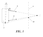
- the wheel can be considered as a rigid solid having six degrees of freedom, which correspond to three rotations and three translations.
- the plane of the wheel being understood as that which is perpendicular to an axis of the wheel which passes through the area of contact of the tire of the wheel with the ground.
- the rotation about a vertical axis passing through the center of the wheel is considered, such rotation being a degree of freedom which is operated by means of the steering wheel of the vehicle.
- the angle formed by the plane of the wheel and the actual direction of the movement is the slip angle.
- the tread in the area of contact with the ground offers a rotation resistance caused by the friction existing between the rubber of the tire and the ground, usually the road asphalt.
- the contact tread is thus deformed and experiences a reorientation towards the direction of the wheel.
- the angular difference between the direction of the tread and the direction of the wheel is the slip angle, which provides a lateral force which also depends on the load supported by said wheel.
- ADAS advanced driver assistance systems
- LDW Lane Departure Warning
- LCA lane change assistant
- suspensions comprising devices which allow changing the camber angle of the wheel, as described, for example, in Japanese patent number JP-2002063698 , in which the location of the point of assembly of the suspension to the chassis of the upper fork is modified, such that said changes in the position of the points of fastening the tie bars to the chassis cause alterations in the position of the roll center of the vehicle, which entails a great drawback from the point of view of stability of the vehicle.
- the roll axis is defined as a point of intersection between a plane of symmetry of the automotive vehicle and a plane containing the point of support of the wheel on the ground with a straight line defined as the intersection between the planes of support of the wheel on the chassis, i.e., there is a first plane containing the upper support elements, which is usually a triangle, of the suspension and a second plane in which the lower support elements of the suspension, are contained, which is usually another triangle, such that said two planes intersect in a line forming a plane with the point of contact between the wheel and the ground.
- the intersection of said plane with the plane of symmetry of the vehicle is the roll axis.
- United States patent number US-4895383 describes a method and a mechanism for controlling the camber angle in the rear wheels.
- Said mechanism incorporates detectors of the orientation direction of the wheel, devices and actuators for varying the camber angle and a control unit responsible for capturing the information of the sensors and sending the suitable control signal for controlling at least one wheel.
- These devices comprise an actuator operated by an electric motor which pushes transversely in the upper part of the wheel, or in any upper support element of the suspension of the wheel.
- These suspensions also usually comprise a stub axle, which is the element supporting the wheel, a lower support triangle of the suspension which is attached on one side to the stub axle and on the other side to the chassis of the vehicle, an upper support triangle of the suspension which is also attached on one side to the stub axle and on the other side to the chassis of the vehicle, and a steering rod which is attached on one side to the stub axle and on the other side to the steering elements which are connected to the steering wheel.
- a first aspect of the present invention relates to a suspension system for automotive vehicles and a second aspect of the invention relates to an automotive vehicle comprising said system.
- the suspension system object of the invention has the capacity to modify the camber angle of at least one wheel, said camber angle being an angle between a vertical plane of symmetry of the wheel and a vertical plane.
- the variation of the camber angle of the wheel allows introducing a lateral force causing the vehicle to turn in direction or the other. This allows, for example, increasing the stability of the vehicle in determined situations, optimizing the use of a tire or modifying the course, for example, in lane departure correction systems, comprising the collaboration of sensors and at least one control unit.
- An automotive vehicle capable of managing its course independently from the conventional steering system entails an added value in terms of maneuverability, since in the event of an emergency it assists but does replace the driver or his capacity of making a decision regarding the course he wishes to maintain, which is especially relevant in the event of failure or malfunction of the device object of the invention.
- the invention contemplates its use and integration in vehicle architectures which are currently being developed, such as electric and hybrid automobiles, which are starting to incorporate steering systems based on by wire technologies.
- These steering systems propose, in some cases, alternatives to the conventional steering wheel by means of control levers which allow modifying different parameters of the configuration of the vehicle for driving it.
- This by wire technology involves replacing mechanical transmission elements with command signals by means of wires and the drives with electric motors commanded by said signals.
- the sector towards which this invention is focused is the automotive sector, particularly the field of special vehicles, such as electric or hybrid vehicles, conventional vehicles, high-end vehicles and sport utility vehicles, or SUVs.
- special vehicles such as electric or hybrid vehicles, conventional vehicles, high-end vehicles and sport utility vehicles, or SUVs.
- the suspension system for automotive vehicles proposed by the invention has the capacity to independently control the camber angle, and is configured to modify a camber angle of at least one wheel, wherein said at least one wheel is supported by a stub axle which in a lower area, below an axis of rotation of said at least one wheel, is articulated by means of a ball joint to a lower support, which can consist of a lower triangle which is in turn articulated by means of a ball joint to a chassis of the vehicle.
- the system comprises a steering rod which is articulated by means of a ball joint to the stub axle and to steering elements, at the ends thereof.
- Said connection rod is contained in a plane defined by the lower support.
- the point of attachment between the steering rod and the stub axle is contained in an instantaneous axis of rotation of the lower support with respect to said stub axle in any situation of the suspension system, i.e., in any position of the lower support.
- the steering rod is a bar connected to steering elements of the automotive vehicle, specifically to the steering rack, articulated by means of a ball joint. Said articulation by means of a ball joint restricts the three translations and allows the three rotations.
- the opposite end of the steering rod is in turn connected to the stub axle, also by means of a ball joint.
- the system comprises a connection joint articulated at the upper part by means of a ball joint to the stub axle, and a tie bar which at a first end is articulated by means of a ball joint to the connection joint, and at a second end is articulated by means of a ball joint to the chassis of the vehicle.
- the system also comprises an actuator element rigidly attached to the connection joint and in an articulated manner by means of a ball joint to the chassis, said actuator element is configured to modify the camber angle of said at least one wheel by means of modifying the length of said actuator element.
- the upper support elements of the suspension comprise the actuator element which allows varying the camber angle and which is attached on one hand to the chassis of the vehicle and on the other hand in a rigid manner to the connection joint located at the upper part of the stub axle.
- the upper support elements of the suspension also comprise a tie bar attached in an articulated manner to the connection joint at one end and to the chassis of the vehicle at its opposite end.
- This tie bar is arranged in a direction substantially parallel to the forward movement direction of the vehicle, such that the effect of the longitudinal variation of the actuator element in the suspension is minimized.
- the suspension system object of the invention allows modifying the camber angle by means of a special configuration or architecture which allows preventing the aforementioned problems.
- the actuator element is contained in the plane formed by the upper support elements of the suspension so that the extension or compression of the pin and therefore of the actuator element does not affect the position of the roll center, such that the shifts of the actuator element occur coinciding with a line of projection of the upper plane and, therefore, the changes in the camber angle of the wheel caused by the actuator element do not result in a modification of the roll center.
- the steering rod is attached to the stub axle at a point of the axis of rotation between the stub axle and the lower support elements of the suspension.
- the movements of the wheel due to the actuation of the actuator element of the camber angle are thus transparent to the steering and therefore do not transmit any movement to the steering wheel.
- the lower connection element is articulated by means of two connections to the chassis of the vehicle, which are preferably two spherical joints although they can also be two revolute joints with colinear axis.
- the projection of the instantaneous axis of rotation of the relative movement between the stub axle and the lower support on a plane transverse to the forward movement direction coincides with the point of attachment of the steering rod and the stub axle.
- the tie bar is oriented according to an angle not greater than 45o with respect to an axis perpendicular to the axis of rotation of said at least one wheel.
- the location of the tie bar with respect to the horizontal plane is defined by the geometry of the assembly as occurs with the actuator element.
- the orientation of the tie bar is specified by a parameter ⁇ , which is the angle of the tie bar with respect to a straight line defining the travel direction.
- This parameter ⁇ must be less than or equal to 45o and the greater the horizontality of the tie bar in the travel direction, the lower the variation that it introduces in the caster of the suspension.
- the arc described by the point of connection of the tie bar with the attachment joint will be more horizontal the greater the radius defined by the tie bar.
- the actuator element is oriented according to an angle comprised between -15o and 15o with respect to an axis parallel to the axis of rotation of said at least one wheel.
- the actuator element preferably comprises a cylinder and a pin configured to be operated by driving means, which can consist of an electric motor. It is also contemplated that said actuator element comprises at least one position sensor configured to detect the position of said actuator element.
- the actuator element comprises a non-return system configured to withstand stresses from said at least one wheel and preventing a transmission of said stresses to the actuator element.
- the intention is to prevent a modification of the length of the actuator element as a consequence of the stresses that it receives in its connection to the connection joint, i.e., that it moves only when it is actuated and not as a consequence of bumps or other forces that it has to withstand.
- the system has a single actuator element, with a non-return system, such that it only uses a single electric or hydraulic actuator incorporating a position sensor for modifying the camber angle, can be emphasized.
- the design of the remaining elements object of the invention prevents the need for additional actuation elements to prevent adverse effects in the suspension levels which would otherwise have to be compensated by additional actuators synchronized with the main actuator.
- the system presented can be equivalent to a conventional suspension by substituting the actuator with a rod of a fixed length, provided that the remaining elements of the suspension are designed with the particularities described in the claims.
- the system comprises a non-return system which can consist of a worm screw system such that, in the event of loss of electric current, the stresses from the wheel are not capable of modifying the configuration of the system, thus preventing a potentially dangerous situation.
- the length of the actuator element is varied for modifying the camber of the wheel by modifying the upper part of the stub axle, therefore the connection of said actuator is performed at the upper part of the stub axle.
- a second aspect of the invention relates to an automotive vehicle comprising a suspension system according to any of those defined above.
- this system for modifying the course could be used to provide the steering system of the vehicle with a specific and convenient alternative for controlling the orientation of the wheel by means of a control lever. This would allow operating a lever type steering control which allows controlling the turning by means of camber angle or by means of slip angle of the wheel in an independent manner.
- Another object of this invention is to provide the steering system with a more comfortable driving means, thus reducing the number of turns of the steering control, favoring the maneuverability.
- An advantage of the present invention is the simplicity for its implementation since it is formed by a relatively small number of components which can be chosen from among a wide range of typologies.
- it uses two sensors, a lane departure warning sensor and a dynamic vehicle behavior sensor, a controller and camber angle modifiers, one in each opposite wheel of one and the same axle.
- the sensors can be of several types for detecting the lateral course reference line and the lateral force of the vehicle;
- the controller can be an electronic unit which is independent or included in an original Electronic Control Unit, ECU, of the vehicle.
- Another advantage of this invention is the wide range of vehicles in which it can be implemented, from conventional four-wheel vehicles, both in the front axle and in the rear axle and even in both. It can also be used in three-wheel vehicles, either in the opposite wheels or in the third wheel. And it can be implemented for vehicles with a larger number of wheels such as car trains.
- the present invention proposes using the lateral force induced by the camber of the tire as a system for varying the steering thereof.
- the management of the variation of this parameter by means of a control system provides the vehicle with a system for varying the course without affecting the conventional steering, allowing the compensation of lane departures resulting from driver distractions. Nevertheless, it is important to emphasize that the magnitude of the induced force is approximately 10% of the force which is introduced when the steering wheel is rotated by means of the slip angle. The driver will thus always be able to correct the steering variation by means of the conventional steering system in the event of a possible failure or malfunction of the proposed system.
- the driver's perception is positive, since the vehicle remains on a safe course but without noticing a variation in the steering wheel in an autonomous manner, whereby the feeling of control is not lost.
- Another differential feature of the invention is the placement of the point of attachment of the steering rod at the height of the connection of the lower attachment support or triangle, thus preventing modifications of the initial geometry of the steering.
- the essential inventive value resides in the system for varying the camber angle as a mechanism for controlling the course of the vehicle and its implementation by means of a relatively simple mechanism, which allows not interfering in the capabilities or in the configuration of conventional steering.
- the invention contemplates being applied as an active safety system to prevent lane departures of the vehicle.
- the system of the invention is a preventive safety system which allows preventing the departure of the vehicle from the safe course under determined driving conditions in which the direction of the forces changes when the orientation of the wheel is modified to prevent the vehicle from crossing over the continuous line of the side.
- the proposed invention is a system which, by acting on the camber angle of the wheel, allows introducing a determined lateral force to correct the course of the vehicle without the actuation of the steering wheel. Therefore, the course correction proposed by the invention comprises a system and a method which are defined in the following paragraphs.
- the invention contemplates a method of adjusting the camber angle or course correction process.
- Said system for varying the course based on the camber angle of the wheel mainly comprises three levels.
- a network of sensors sends different information signals.
- the first signal is from the lane departure LDW sensor, which consists of a sensor configured to detect if the vehicle is going to depart from a safe course under determined conditions, as well as to detect continuous lines, obstacles, etc.
- the second signal consists of a speed limit below which the system is not activated and is from the speed sensor of the vehicle.
- a visual lane change indicator preferably a turn signal
- the system does not work either, and additionally, if the user has decided to disconnect the system, no original lane departure signal is activated either.
- the system has information about the lateral acceleration of the vehicle, which is a third signal, as well as about the turning of the steering wheel and/or turning speed of the steering wheel, which is a fourth signal.
- an electronic control unit which can be a specific one for the system, or it can be a functionality included in the original electronic control unit of the vehicle, which evaluates the information of the different sensors and decides as to the necessity to act on the camber angle of the wheel, in which case it determines the magnitude of the shift of the actuator element, which is the cause of the direct modification on the wheel.
- an electronic control unit which evaluates the information of the different sensors and decides as to the necessity to act on the camber angle of the wheel, in which case it determines the magnitude of the shift of the actuator element, which is the cause of the direct modification on the wheel.
- the intentional variation of the driver or disconnection of the system for example, the orientation of the wheel is not changed.
- the cycle is fed back and iterated as many times as the control unit considers necessary until recovering the course.
- the operating mode according to the order which the electronic control unit processes consists of sending a command signal to the actuator element which generates the lateral shift necessary for introducing an angular variation of the wheel with respect to the vertical plane thereof.
- the suspension system for automotive vehicles and the automotive vehicle comprising said system proposed by the invention constitute an advance in suspensions and vehicles used up until now and fully solves in a satisfactory manner the drawbacks set forth above, insofar as what is done in racing vehicles in which this length is frequently varied to modify the camber angle without changing critical dimensions of the suspension such as the height of the roll center by means of other devices.
- the invention does not modify the points of anchoring the elements, the changes in the position of the points of fastening the tie bars to the chassis cause moderate changes in the position of the roll center, so the device object of the invention is advantageous with respect to those which modify the position of the inner point of anchoring the tie bar.
- the actuator element changes its length, scarcely modifying other levels, which allows minimal alteration in the caster of the wheel.
- the need to have three kinematic pairs in a conventional suspension of the type of superimposed triangles means that in the event of incorporating an actuator to modify the geometry of the fork, and accordingly the levels of the suspension, the arrangement must be such that the effect on other levels such as the caster is not affected.
- the device of the invention comprises a longitudinal tie bar attached to the remaining steering elements of the vehicle by means of a spherical ball joint and with a defined length to prevent the excessive variation of the caster angle in the compression and extension of the suspension.
- This arrangement of longitudinal tie bars in the suspension also improves the resistant performance of the tie bar, because during braking, the situation which typically generates the greatest loads in a suspension, it causes a tensile stress on the tie bar, offering great rigidity of the system with a minimal weight, because it is the optimal form of work of elements of this type.
- the user does not need to modify the turning angle of the steering wheel so that the vehicle changes direction because the actuator element receives the order from the control system.
- the driver of the vehicle must simply maintain the position of the steering wheel and the device commanded by the control system varies the direction of the vehicle by means of the development of the lateral force upon modifying the camber angle.
- the turning levels of the steering are not modified by the arrangement of the steering tie bar in the same plane of the triangle or lower fork of the suspension.
- the device object of the invention prevents having to make any correction on the steering tie bar of the vehicle, because during the modification of the camber angle, the axis of rotation of the stub axle is determined by the ball joint of the lower support or fork and the end of the steering tie bar. Modifications in the toe-in of the wheels are thus prevented. If the device does not use this arrangement, a change of the camber angle in the wheels would cause changes in the angle of the wheel modified by the conventional steering tie bar, coupling the effects of the modification of the camber angle with said angle.
- the arrangement of the fork or triangle coinciding with the steering tie bar further prevents the effect referred to as bump steer, which varies the orientation of the wheels exerting parasitic lateral forces when one of the wheels goes over a bump.
- the architecture of the system of the invention is highly versatile and allows implementing functions of different types, such as evasive maneuvers, platooning and other ADAS systems relating to the steering of the vehicle such that the user maintains control over the slip angle, which is what generates the greatest amount of lateral force.
- the device is considered to be non-intrusive in driving and has the advantage that it does not require modifying the platform of the vehicle.
- the system object of the invention allows maximizing the lateral force for a determined tire size, which involves a reduction of consumption of the vehicle, because the same lateral force can be generated with narrower tires, being equivalent from the safety point of view. This is due to the fact that tires with a smaller front section and lower friction losses reduce consumption.
- the capacity to modify the camber angle allows having an automated adjustment, which results in making better use of the tire, prolonging its service life because it assures uniform wear, which in turn results in a benefit for the environment.
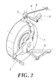
- the suspension system for automotive vehicles proposed by the invention is configured to modify a camber angle of a wheel (2), wherein said wheel (2) is supported by a stub axle (7) which in a lower area, below an axis of rotation of the wheel (2), is articulated by means of a ball joint to a lower support (8) consisting of a lower triangle which is in turn articulated by means of a ball joint to a chassis of the vehicle.
- the system comprises a steering rod (1) which is articulated by means of a ball joint to the stub axle (7) and to steering elements at respective ends.
- Said connection rod (1) is contained in a plane defined by the lower support (8).
- the point of attachment between the steering rod (1) and the stub axle (7) is contained in an instantaneous axis of rotation of the lower support (8) with respect to said stub axle (7) in any situation of the suspension system, as can be seen in Figures 3 and 4 .
- connection joint (3) articulated at the upper part by means of a ball joint to the stub axle (7), and a tie bar (4) which at a first end is articulated by means of a ball joint to the connection joint (3), and at a second end is articulated by means of a ball joint to the chassis of the vehicle.
- the system also comprises an actuator element (6) rigidly attached to the connection joint (3) and in an articulated manner by means of a ball joint to the chassis, said actuator element (6) is configured to modify the camber angle of the wheel (2) by means of modifying the length of said actuator element (6).
- the actuator element (6) is attached on one hand to the chassis of the vehicle and on the other hand it is rigidly attached to the connection joint (3) located at the upper part of the stub axle (7).
- Said actuator element (6) comprises a cylinder and a pin configured to be operated by an electric motor.
- the tie bar (4) is also attached in an articulated manner to the connection joint (3) at one end and to the chassis of the vehicle at its opposite end.
- This tie bar (4) is arranged in a direction substantially parallel to the forward movement direction of the vehicle, such that the effect of the longitudinal variation of the actuator element (6) in the suspension is minimized, as can be seen in Figure 1 , where it can be seen that the actuator element (6) is contained in the plane formed by the upper support elements of the suspension such that the extension or compression of the actuator element (6) does not affect the position of the roll center (10).
- the shifts of the actuator element (6) occur coinciding with a line of projection of the upper plane and, therefore, the changes in the camber angle of the wheel caused by the actuator element (6) do not result in a modification of the roll center (10).
- the lower connection element (8) is articulated by means of two connections to the chassis of the vehicle, which are two revolute joints with colinear axis.
- the tie bar (4) is oriented according to an angle not greater than 45o with respect to an axis perpendicular to the axis of rotation of the wheel (2), as can be seen in Figure 5 .
- the orientation of the tie bar (4) is specified by a parameter ⁇ , which is the angle of the tie bar with respect to a straight line defined by the travel direction. This parameter ⁇ must be less than or equal to 45o and the greater the horizontality of the tie bar (4) in the travel direction, the lower the variation that it introduces in the caster of the suspension.
- the actuator element (6) is oriented according to an angle comprised between -15o and 15o with respect to an axis parallel to the axis of rotation of the wheel (2).
- Figure 5 shows the position and orientation of the actuator element (6) according to a plan view, which is defined according to its orientation with respect to a direction transverse to travel.
- the actuator element (6) has an orientation defined by a parameter ⁇ which is comprised between -15o and 15o, such that the variations of the camber angle caused by the actuator element (6) do not affect the rest of the geometry of the suspension assembly, specifically, they do not affect the position of the roll center (10). This is justified because the roll center (10) is located by means of a straight line containing the actuator element (6), specifically, it is obtained in the intersection of the straight line with the longitudinal plane of symmetry of the vehicle (9), as shown in Figure 1 .
- the actuator element (6) is actuated by driving means (5), consisting of an electric motor.
- the actuator element (6) also comprises position sensors configured to detect the position of said actuator element (6).
- the actuator element (6) comprises a non-return system configured to prevent a transmission of stresses from the wheel (2) to said actuator element (6).
Landscapes
- Engineering & Computer Science (AREA)
- Mechanical Engineering (AREA)
- Chemical & Material Sciences (AREA)
- Combustion & Propulsion (AREA)
- Transportation (AREA)
- Vehicle Body Suspensions (AREA)
- Steering-Linkage Mechanisms And Four-Wheel Steering (AREA)
Applications Claiming Priority (1)
| Application Number | Priority Date | Filing Date | Title |
|---|---|---|---|
| PCT/ES2008/000081 WO2009101218A2 (es) | 2008-02-14 | 2008-02-14 | Sistema de suspensión para vehículos automóviles y vehículo automóvil que comprende dicho sistema |
Publications (3)
| Publication Number | Publication Date |
|---|---|
| EP2253489A2 true EP2253489A2 (de) | 2010-11-24 |
| EP2253489A4 EP2253489A4 (de) | 2011-07-27 |
| EP2253489B1 EP2253489B1 (de) | 2015-04-08 |
Family
ID=40957315
Family Applications (1)
| Application Number | Title | Priority Date | Filing Date |
|---|---|---|---|
| EP08736685.2A Not-in-force EP2253489B1 (de) | 2008-02-14 | 2008-02-14 | Aufhängungssystem für kraftfahrzeuge und das system enthaltendes kraftfahrzeug |
Country Status (2)
| Country | Link |
|---|---|
| EP (1) | EP2253489B1 (de) |
| WO (1) | WO2009101218A2 (de) |
Cited By (1)
| Publication number | Priority date | Publication date | Assignee | Title |
|---|---|---|---|---|
| CN112829821A (zh) * | 2019-11-22 | 2021-05-25 | 财团法人工业技术研究院 | 转向装置及方法 |
Families Citing this family (3)
| Publication number | Priority date | Publication date | Assignee | Title |
|---|---|---|---|---|
| CN101826125B (zh) * | 2010-03-25 | 2011-12-14 | 奇瑞汽车股份有限公司 | 一种设计麦弗逊悬架的方法 |
| US10773566B2 (en) * | 2018-06-11 | 2020-09-15 | Rivian Ip Holdings, Llc | Suspension with active damping to tune caster dynamics |
| US11731477B2 (en) | 2020-12-21 | 2023-08-22 | Ford Global Technologies, Llc | Enhanced vehicle stability |
Family Cites Families (12)
| Publication number | Priority date | Publication date | Assignee | Title |
|---|---|---|---|---|
| DE3145988C2 (de) * | 1981-11-20 | 1985-10-24 | Daimler-Benz Ag, 7000 Stuttgart | Unabhängige Radaufhängung für Vorderräder von Personenkraftwagen |
| EP0246116B1 (de) * | 1986-05-16 | 1992-04-15 | Honda Giken Kogyo Kabushiki Kaisha | Sturzregelungssystem für ein Kraftfahrzeug |
| JPS63263172A (ja) * | 1987-04-21 | 1988-10-31 | Honda Motor Co Ltd | 四輪操舵車における後輪の対地キヤンバ制御方法及び装置 |
| FR2629036B1 (fr) * | 1988-03-23 | 1990-12-28 | Peugeot | Dispositif de pivotement d'une roue directrice de vehicule automobile |
| DE4020547A1 (de) * | 1990-06-28 | 1992-01-02 | Porsche Ag | Vorrichtung zur aktiven verstellung eines kraftfahrzeugrades |
| KR970011358B1 (ko) * | 1992-10-13 | 1997-07-10 | 미쯔비시 지도샤 고교 가부시끼가이샤 | 차량의 휠 얼라인먼트 제어방법 및 제어장치 |
| KR970000621B1 (ko) * | 1992-10-14 | 1997-01-16 | 미쯔비시 지도샤 고교 가부시끼가이샤 | 차량용 서스펜션 장치의 얼라인먼트 제어장치 및 제어방법 |
| JPH06344737A (ja) * | 1993-06-07 | 1994-12-20 | Toyota Motor Corp | ダブルウィシュボーン式サスペンション |
| DE19836440A1 (de) * | 1998-08-12 | 2000-02-24 | Daimler Chrysler Ag | Radaufhängung für Kraftfahrzeuge, insbesondere unabhängige Radaufhängung für Personenkraftwagen |
| JP3705094B2 (ja) | 2000-08-22 | 2005-10-12 | 日産自動車株式会社 | 車線追従走行制御装置 |
| FR2833233B1 (fr) | 2001-12-12 | 2004-02-27 | Michelin Soc Tech | Dispositif de suspension d'une roue |
| FR2890631B1 (fr) * | 2005-09-15 | 2009-01-23 | Renault Sas | Systeme de direction de type sans liaison mecanique et vehicule associe |
-
2008
- 2008-02-14 WO PCT/ES2008/000081 patent/WO2009101218A2/es not_active Ceased
- 2008-02-14 EP EP08736685.2A patent/EP2253489B1/de not_active Not-in-force
Cited By (2)
| Publication number | Priority date | Publication date | Assignee | Title |
|---|---|---|---|---|
| CN112829821A (zh) * | 2019-11-22 | 2021-05-25 | 财团法人工业技术研究院 | 转向装置及方法 |
| US11548552B2 (en) | 2019-11-22 | 2023-01-10 | Industrial Technology Research Institute | Steering device and method thereof |
Also Published As
| Publication number | Publication date |
|---|---|
| EP2253489A4 (de) | 2011-07-27 |
| WO2009101218A2 (es) | 2009-08-20 |
| EP2253489B1 (de) | 2015-04-08 |
| WO2009101218A3 (es) | 2010-11-18 |
Similar Documents
| Publication | Publication Date | Title |
|---|---|---|
| CN102066184B (zh) | 车辆的转向装置以及该转向装置的设定装置 | |
| US7690737B2 (en) | Method of controlling an automotive vehicle having a trailer | |
| US7165644B2 (en) | Method and apparatus of controlling an automotive vehicle using brake-steer as a function of steering wheel torque | |
| US8380416B2 (en) | Method and apparatus for controlling brake-steer in an automotive vehicle in reverse | |
| US6959970B2 (en) | Method and apparatus for controlling a trailer and an automotive vehicle with a yaw stability control system | |
| US7401870B2 (en) | Method and apparatus to enhance brake-steer of a vehicle using a controllable suspension component | |
| US7950751B2 (en) | Method and apparatus for maintaining a trailer in a straight position relative to the vehicle | |
| US7401871B2 (en) | Method of controlling an automotive vehicle having a trailer using rear axle slip angle | |
| JP4715351B2 (ja) | ステアリング制御システム | |
| US7229139B2 (en) | Control system for brake-steer assisted parking and method therefor | |
| US6991061B2 (en) | System for steering a vehicle, having a degraded mode in the event of failure of a wheel steering actuator | |
| US7070247B2 (en) | Method and apparatus for controlling brake-steer in an automotive vehicle in a forward and reverse direction | |
| US20050206225A1 (en) | Method and apparatus for predicting the position of a trailer relative to a vehicle | |
| US20050206231A1 (en) | Method and apparatus for controlling an automotive vehicle using brake-steer and normal load adjustment | |
| US20050209762A1 (en) | Method and apparatus for controlling a vehicle using an object detection system and brake-steer | |
| US20050206226A1 (en) | Method and apparatus for controlling an automotive vehicle in a u-turn | |
| JP4821454B2 (ja) | 車両の走行制御装置 | |
| EP2253489B1 (de) | Aufhängungssystem für kraftfahrzeuge und das system enthaltendes kraftfahrzeug | |
| JP2007160998A (ja) | 車輌の操舵制御装置 | |
| EP2585358B1 (de) | Verfahren zum elektromechanischen einstellen eines lenkwinkels und kraftfahrzeug mit einer elektromechanischen lenkung | |
| WO2019189095A1 (ja) | ステアリングシステムおよびこれを備えた車両 | |
| JP3881978B2 (ja) | 産業用トラックを操縦する方法および装置 | |
| CN209972569U (zh) | 一种机械性能可调的车桥、底盘及汽车 | |
| WO2007031817A1 (en) | Method of controlling a steer by wire steering system | |
| US6435530B1 (en) | Anti-roll mechanism for vehicle suspension system |
Legal Events
| Date | Code | Title | Description |
|---|---|---|---|
| PUAI | Public reference made under article 153(3) epc to a published international application that has entered the european phase |
Free format text: ORIGINAL CODE: 0009012 |
|
| 17P | Request for examination filed |
Effective date: 20100913 |
|
| AK | Designated contracting states |
Kind code of ref document: A2 Designated state(s): AT BE BG CH CY CZ DE DK EE ES FI FR GB GR HR HU IE IS IT LI LT LU LV MC MT NL NO PL PT RO SE SI SK TR |
|
| AX | Request for extension of the european patent |
Extension state: AL BA MK RS |
|
| R17D | Deferred search report published (corrected) |
Effective date: 20101118 |
|
| A4 | Supplementary search report drawn up and despatched |
Effective date: 20110628 |
|
| DAX | Request for extension of the european patent (deleted) | ||
| GRAP | Despatch of communication of intention to grant a patent |
Free format text: ORIGINAL CODE: EPIDOSNIGR1 |
|
| RIC1 | Information provided on ipc code assigned before grant |
Ipc: B62D 5/04 20060101ALI20140828BHEP Ipc: B60G 17/016 20060101ALI20140828BHEP Ipc: B62D 17/00 20060101ALI20140828BHEP Ipc: B60G 3/20 20060101AFI20140828BHEP Ipc: B60G 7/00 20060101ALI20140828BHEP |
|
| INTG | Intention to grant announced |
Effective date: 20140929 |
|
| GRAS | Grant fee paid |
Free format text: ORIGINAL CODE: EPIDOSNIGR3 |
|
| GRAA | (expected) grant |
Free format text: ORIGINAL CODE: 0009210 |
|
| AK | Designated contracting states |
Kind code of ref document: B1 Designated state(s): AT BE BG CH CY CZ DE DK EE ES FI FR GB GR HR HU IE IS IT LI LT LU LV MC MT NL NO PL PT RO SE SI SK TR |
|
| REG | Reference to a national code |
Ref country code: GB Ref legal event code: FG4D |
|
| REG | Reference to a national code |
Ref country code: CH Ref legal event code: EP |
|
| REG | Reference to a national code |
Ref country code: IE Ref legal event code: FG4D |
|
| REG | Reference to a national code |
Ref country code: AT Ref legal event code: REF Ref document number: 720257 Country of ref document: AT Kind code of ref document: T Effective date: 20150515 |
|
| REG | Reference to a national code |
Ref country code: DE Ref legal event code: R096 Ref document number: 602008037559 Country of ref document: DE Effective date: 20150521 |
|
| REG | Reference to a national code |
Ref country code: AT Ref legal event code: MK05 Ref document number: 720257 Country of ref document: AT Kind code of ref document: T Effective date: 20150408 |
|
| REG | Reference to a national code |
Ref country code: NL Ref legal event code: VDEP Effective date: 20150408 |
|
| REG | Reference to a national code |
Ref country code: LT Ref legal event code: MG4D |
|
| PG25 | Lapsed in a contracting state [announced via postgrant information from national office to epo] |
Ref country code: NL Free format text: LAPSE BECAUSE OF FAILURE TO SUBMIT A TRANSLATION OF THE DESCRIPTION OR TO PAY THE FEE WITHIN THE PRESCRIBED TIME-LIMIT Effective date: 20150408 |
|
| PG25 | Lapsed in a contracting state [announced via postgrant information from national office to epo] |
Ref country code: NO Free format text: LAPSE BECAUSE OF FAILURE TO SUBMIT A TRANSLATION OF THE DESCRIPTION OR TO PAY THE FEE WITHIN THE PRESCRIBED TIME-LIMIT Effective date: 20150708 Ref country code: ES Free format text: LAPSE BECAUSE OF FAILURE TO SUBMIT A TRANSLATION OF THE DESCRIPTION OR TO PAY THE FEE WITHIN THE PRESCRIBED TIME-LIMIT Effective date: 20150408 Ref country code: PT Free format text: LAPSE BECAUSE OF FAILURE TO SUBMIT A TRANSLATION OF THE DESCRIPTION OR TO PAY THE FEE WITHIN THE PRESCRIBED TIME-LIMIT Effective date: 20150810 Ref country code: HR Free format text: LAPSE BECAUSE OF FAILURE TO SUBMIT A TRANSLATION OF THE DESCRIPTION OR TO PAY THE FEE WITHIN THE PRESCRIBED TIME-LIMIT Effective date: 20150408 Ref country code: FI Free format text: LAPSE BECAUSE OF FAILURE TO SUBMIT A TRANSLATION OF THE DESCRIPTION OR TO PAY THE FEE WITHIN THE PRESCRIBED TIME-LIMIT Effective date: 20150408 Ref country code: LT Free format text: LAPSE BECAUSE OF FAILURE TO SUBMIT A TRANSLATION OF THE DESCRIPTION OR TO PAY THE FEE WITHIN THE PRESCRIBED TIME-LIMIT Effective date: 20150408 |
|
| PG25 | Lapsed in a contracting state [announced via postgrant information from national office to epo] |
Ref country code: LV Free format text: LAPSE BECAUSE OF FAILURE TO SUBMIT A TRANSLATION OF THE DESCRIPTION OR TO PAY THE FEE WITHIN THE PRESCRIBED TIME-LIMIT Effective date: 20150408 Ref country code: IS Free format text: LAPSE BECAUSE OF FAILURE TO SUBMIT A TRANSLATION OF THE DESCRIPTION OR TO PAY THE FEE WITHIN THE PRESCRIBED TIME-LIMIT Effective date: 20150808 Ref country code: AT Free format text: LAPSE BECAUSE OF FAILURE TO SUBMIT A TRANSLATION OF THE DESCRIPTION OR TO PAY THE FEE WITHIN THE PRESCRIBED TIME-LIMIT Effective date: 20150408 Ref country code: GR Free format text: LAPSE BECAUSE OF FAILURE TO SUBMIT A TRANSLATION OF THE DESCRIPTION OR TO PAY THE FEE WITHIN THE PRESCRIBED TIME-LIMIT Effective date: 20150709 |
|
| REG | Reference to a national code |
Ref country code: DE Ref legal event code: R097 Ref document number: 602008037559 Country of ref document: DE |
|
| PG25 | Lapsed in a contracting state [announced via postgrant information from national office to epo] |
Ref country code: EE Free format text: LAPSE BECAUSE OF FAILURE TO SUBMIT A TRANSLATION OF THE DESCRIPTION OR TO PAY THE FEE WITHIN THE PRESCRIBED TIME-LIMIT Effective date: 20150408 Ref country code: DK Free format text: LAPSE BECAUSE OF FAILURE TO SUBMIT A TRANSLATION OF THE DESCRIPTION OR TO PAY THE FEE WITHIN THE PRESCRIBED TIME-LIMIT Effective date: 20150408 |
|
| PLBE | No opposition filed within time limit |
Free format text: ORIGINAL CODE: 0009261 |
|
| STAA | Information on the status of an ep patent application or granted ep patent |
Free format text: STATUS: NO OPPOSITION FILED WITHIN TIME LIMIT |
|
| PG25 | Lapsed in a contracting state [announced via postgrant information from national office to epo] |
Ref country code: RO Free format text: LAPSE BECAUSE OF NON-PAYMENT OF DUE FEES Effective date: 20150408 Ref country code: CZ Free format text: LAPSE BECAUSE OF FAILURE TO SUBMIT A TRANSLATION OF THE DESCRIPTION OR TO PAY THE FEE WITHIN THE PRESCRIBED TIME-LIMIT Effective date: 20150408 Ref country code: SK Free format text: LAPSE BECAUSE OF FAILURE TO SUBMIT A TRANSLATION OF THE DESCRIPTION OR TO PAY THE FEE WITHIN THE PRESCRIBED TIME-LIMIT Effective date: 20150408 Ref country code: PL Free format text: LAPSE BECAUSE OF FAILURE TO SUBMIT A TRANSLATION OF THE DESCRIPTION OR TO PAY THE FEE WITHIN THE PRESCRIBED TIME-LIMIT Effective date: 20150408 |
|
| 26N | No opposition filed |
Effective date: 20160111 |
|
| PG25 | Lapsed in a contracting state [announced via postgrant information from national office to epo] |
Ref country code: IT Free format text: LAPSE BECAUSE OF FAILURE TO SUBMIT A TRANSLATION OF THE DESCRIPTION OR TO PAY THE FEE WITHIN THE PRESCRIBED TIME-LIMIT Effective date: 20150408 |
|
| PG25 | Lapsed in a contracting state [announced via postgrant information from national office to epo] |
Ref country code: SI Free format text: LAPSE BECAUSE OF FAILURE TO SUBMIT A TRANSLATION OF THE DESCRIPTION OR TO PAY THE FEE WITHIN THE PRESCRIBED TIME-LIMIT Effective date: 20150408 Ref country code: BE Free format text: LAPSE BECAUSE OF NON-PAYMENT OF DUE FEES Effective date: 20160229 |
|
| PG25 | Lapsed in a contracting state [announced via postgrant information from national office to epo] |
Ref country code: BE Free format text: LAPSE BECAUSE OF FAILURE TO SUBMIT A TRANSLATION OF THE DESCRIPTION OR TO PAY THE FEE WITHIN THE PRESCRIBED TIME-LIMIT Effective date: 20150408 |
|
| REG | Reference to a national code |
Ref country code: DE Ref legal event code: R119 Ref document number: 602008037559 Country of ref document: DE |
|
| PG25 | Lapsed in a contracting state [announced via postgrant information from national office to epo] |
Ref country code: LU Free format text: LAPSE BECAUSE OF FAILURE TO SUBMIT A TRANSLATION OF THE DESCRIPTION OR TO PAY THE FEE WITHIN THE PRESCRIBED TIME-LIMIT Effective date: 20160214 Ref country code: MC Free format text: LAPSE BECAUSE OF FAILURE TO SUBMIT A TRANSLATION OF THE DESCRIPTION OR TO PAY THE FEE WITHIN THE PRESCRIBED TIME-LIMIT Effective date: 20150408 |
|
| REG | Reference to a national code |
Ref country code: CH Ref legal event code: PL |
|
| GBPC | Gb: european patent ceased through non-payment of renewal fee |
Effective date: 20160214 |
|
| PG25 | Lapsed in a contracting state [announced via postgrant information from national office to epo] |
Ref country code: CH Free format text: LAPSE BECAUSE OF NON-PAYMENT OF DUE FEES Effective date: 20160229 Ref country code: LI Free format text: LAPSE BECAUSE OF NON-PAYMENT OF DUE FEES Effective date: 20160229 |
|
| REG | Reference to a national code |
Ref country code: FR Ref legal event code: ST Effective date: 20161028 |
|
| REG | Reference to a national code |
Ref country code: IE Ref legal event code: MM4A |
|
| PG25 | Lapsed in a contracting state [announced via postgrant information from national office to epo] |
Ref country code: GB Free format text: LAPSE BECAUSE OF NON-PAYMENT OF DUE FEES Effective date: 20160214 Ref country code: IE Free format text: LAPSE BECAUSE OF NON-PAYMENT OF DUE FEES Effective date: 20160214 Ref country code: FR Free format text: LAPSE BECAUSE OF NON-PAYMENT OF DUE FEES Effective date: 20160229 Ref country code: DE Free format text: LAPSE BECAUSE OF NON-PAYMENT OF DUE FEES Effective date: 20160901 |
|
| PG25 | Lapsed in a contracting state [announced via postgrant information from national office to epo] |
Ref country code: SE Free format text: LAPSE BECAUSE OF FAILURE TO SUBMIT A TRANSLATION OF THE DESCRIPTION OR TO PAY THE FEE WITHIN THE PRESCRIBED TIME-LIMIT Effective date: 20150408 |
|
| PG25 | Lapsed in a contracting state [announced via postgrant information from national office to epo] |
Ref country code: MT Free format text: LAPSE BECAUSE OF FAILURE TO SUBMIT A TRANSLATION OF THE DESCRIPTION OR TO PAY THE FEE WITHIN THE PRESCRIBED TIME-LIMIT Effective date: 20150408 |
|
| PG25 | Lapsed in a contracting state [announced via postgrant information from national office to epo] |
Ref country code: HU Free format text: LAPSE BECAUSE OF FAILURE TO SUBMIT A TRANSLATION OF THE DESCRIPTION OR TO PAY THE FEE WITHIN THE PRESCRIBED TIME-LIMIT; INVALID AB INITIO Effective date: 20080214 Ref country code: CY Free format text: LAPSE BECAUSE OF FAILURE TO SUBMIT A TRANSLATION OF THE DESCRIPTION OR TO PAY THE FEE WITHIN THE PRESCRIBED TIME-LIMIT Effective date: 20150408 |
|
| PG25 | Lapsed in a contracting state [announced via postgrant information from national office to epo] |
Ref country code: MT Free format text: LAPSE BECAUSE OF FAILURE TO SUBMIT A TRANSLATION OF THE DESCRIPTION OR TO PAY THE FEE WITHIN THE PRESCRIBED TIME-LIMIT Effective date: 20160229 Ref country code: TR Free format text: LAPSE BECAUSE OF FAILURE TO SUBMIT A TRANSLATION OF THE DESCRIPTION OR TO PAY THE FEE WITHIN THE PRESCRIBED TIME-LIMIT Effective date: 20150408 |
|
| PG25 | Lapsed in a contracting state [announced via postgrant information from national office to epo] |
Ref country code: BG Free format text: LAPSE BECAUSE OF FAILURE TO SUBMIT A TRANSLATION OF THE DESCRIPTION OR TO PAY THE FEE WITHIN THE PRESCRIBED TIME-LIMIT Effective date: 20150408 |