EP2253421A1 - Machining method and machine tool - Google Patents
Machining method and machine tool Download PDFInfo
- Publication number
- EP2253421A1 EP2253421A1 EP08721656A EP08721656A EP2253421A1 EP 2253421 A1 EP2253421 A1 EP 2253421A1 EP 08721656 A EP08721656 A EP 08721656A EP 08721656 A EP08721656 A EP 08721656A EP 2253421 A1 EP2253421 A1 EP 2253421A1
- Authority
- EP
- European Patent Office
- Prior art keywords
- axis
- tool
- feed
- rotary
- rotary feed
- Prior art date
- Legal status (The legal status is an assumption and is not a legal conclusion. Google has not performed a legal analysis and makes no representation as to the accuracy of the status listed.)
- Granted
Links
Images


Classifications
-
- B—PERFORMING OPERATIONS; TRANSPORTING
- B23—MACHINE TOOLS; METAL-WORKING NOT OTHERWISE PROVIDED FOR
- B23Q—DETAILS, COMPONENTS, OR ACCESSORIES FOR MACHINE TOOLS, e.g. ARRANGEMENTS FOR COPYING OR CONTROLLING; MACHINE TOOLS IN GENERAL CHARACTERISED BY THE CONSTRUCTION OF PARTICULAR DETAILS OR COMPONENTS; COMBINATIONS OR ASSOCIATIONS OF METAL-WORKING MACHINES, NOT DIRECTED TO A PARTICULAR RESULT
- B23Q11/00—Accessories fitted to machine tools for keeping tools or parts of the machine in good working condition or for cooling work; Safety devices specially combined with or arranged in, or specially adapted for use in connection with, machine tools
- B23Q11/04—Arrangements preventing overload of tools, e.g. restricting load
-
- B—PERFORMING OPERATIONS; TRANSPORTING
- B23—MACHINE TOOLS; METAL-WORKING NOT OTHERWISE PROVIDED FOR
- B23Q—DETAILS, COMPONENTS, OR ACCESSORIES FOR MACHINE TOOLS, e.g. ARRANGEMENTS FOR COPYING OR CONTROLLING; MACHINE TOOLS IN GENERAL CHARACTERISED BY THE CONSTRUCTION OF PARTICULAR DETAILS OR COMPONENTS; COMBINATIONS OR ASSOCIATIONS OF METAL-WORKING MACHINES, NOT DIRECTED TO A PARTICULAR RESULT
- B23Q15/00—Automatic control or regulation of feed movement, cutting velocity or position of tool or work
- B23Q15/007—Automatic control or regulation of feed movement, cutting velocity or position of tool or work while the tool acts upon the workpiece
-
- G—PHYSICS
- G05—CONTROLLING; REGULATING
- G05B—CONTROL OR REGULATING SYSTEMS IN GENERAL; FUNCTIONAL ELEMENTS OF SUCH SYSTEMS; MONITORING OR TESTING ARRANGEMENTS FOR SUCH SYSTEMS OR ELEMENTS
- G05B19/00—Program-control systems
- G05B19/02—Program-control systems electric
- G05B19/18—Numerical control [NC], i.e. automatically operating machines, in particular machine tools, e.g. in a manufacturing environment, so as to execute positioning, movement or co-ordinated operations by means of program data in numerical form
- G05B19/406—Numerical control [NC], i.e. automatically operating machines, in particular machine tools, e.g. in a manufacturing environment, so as to execute positioning, movement or co-ordinated operations by means of program data in numerical form characterised by monitoring or safety
- G05B19/4062—Monitoring servoloop, e.g. overload of servomotor, loss of feedback or reference
-
- G—PHYSICS
- G05—CONTROLLING; REGULATING
- G05B—CONTROL OR REGULATING SYSTEMS IN GENERAL; FUNCTIONAL ELEMENTS OF SUCH SYSTEMS; MONITORING OR TESTING ARRANGEMENTS FOR SUCH SYSTEMS OR ELEMENTS
- G05B2219/00—Program-control systems
- G05B2219/30—Nc systems
- G05B2219/37—Measurements
- G05B2219/37342—Overload of motor, tool
-
- G—PHYSICS
- G05—CONTROLLING; REGULATING
- G05B—CONTROL OR REGULATING SYSTEMS IN GENERAL; FUNCTIONAL ELEMENTS OF SUCH SYSTEMS; MONITORING OR TESTING ARRANGEMENTS FOR SUCH SYSTEMS OR ELEMENTS
- G05B2219/00—Program-control systems
- G05B2219/30—Nc systems
- G05B2219/37—Measurements
- G05B2219/37632—By measuring current, load of motor
-
- G—PHYSICS
- G05—CONTROLLING; REGULATING
- G05B—CONTROL OR REGULATING SYSTEMS IN GENERAL; FUNCTIONAL ELEMENTS OF SUCH SYSTEMS; MONITORING OR TESTING ARRANGEMENTS FOR SUCH SYSTEMS OR ELEMENTS
- G05B2219/00—Program-control systems
- G05B2219/30—Nc systems
- G05B2219/42—Servomotor, servo controller kind till VSS
- G05B2219/42288—Limit, stop drive current if axis obstructed, blocked, force against stop
-
- G—PHYSICS
- G05—CONTROLLING; REGULATING
- G05B—CONTROL OR REGULATING SYSTEMS IN GENERAL; FUNCTIONAL ELEMENTS OF SUCH SYSTEMS; MONITORING OR TESTING ARRANGEMENTS FOR SUCH SYSTEMS OR ELEMENTS
- G05B2219/00—Program-control systems
- G05B2219/30—Nc systems
- G05B2219/49—Nc machine tool, till multiple
- G05B2219/49155—On collision, reverse motor over certain angle, then stop to avoid bending
-
- G—PHYSICS
- G05—CONTROLLING; REGULATING
- G05B—CONTROL OR REGULATING SYSTEMS IN GENERAL; FUNCTIONAL ELEMENTS OF SUCH SYSTEMS; MONITORING OR TESTING ARRANGEMENTS FOR SUCH SYSTEMS OR ELEMENTS
- G05B2219/00—Program-control systems
- G05B2219/30—Nc systems
- G05B2219/50—Machine tool, machine tool null till machine tool work handling
- G05B2219/50155—Swivel spindle head horizontally
-
- G—PHYSICS
- G05—CONTROLLING; REGULATING
- G05B—CONTROL OR REGULATING SYSTEMS IN GENERAL; FUNCTIONAL ELEMENTS OF SUCH SYSTEMS; MONITORING OR TESTING ARRANGEMENTS FOR SUCH SYSTEMS OR ELEMENTS
- G05B2219/00—Program-control systems
- G05B2219/30—Nc systems
- G05B2219/50—Machine tool, machine tool null till machine tool work handling
- G05B2219/50205—On tool breakage stop machine
-
- Y—GENERAL TAGGING OF NEW TECHNOLOGICAL DEVELOPMENTS; GENERAL TAGGING OF CROSS-SECTIONAL TECHNOLOGIES SPANNING OVER SEVERAL SECTIONS OF THE IPC; TECHNICAL SUBJECTS COVERED BY FORMER USPC CROSS-REFERENCE ART COLLECTIONS [XRACs] AND DIGESTS
- Y10—TECHNICAL SUBJECTS COVERED BY FORMER USPC
- Y10T—TECHNICAL SUBJECTS COVERED BY FORMER US CLASSIFICATION
- Y10T409/00—Gear cutting, milling, or planing
- Y10T409/30—Milling
- Y10T409/303752—Process
-
- Y—GENERAL TAGGING OF NEW TECHNOLOGICAL DEVELOPMENTS; GENERAL TAGGING OF CROSS-SECTIONAL TECHNOLOGIES SPANNING OVER SEVERAL SECTIONS OF THE IPC; TECHNICAL SUBJECTS COVERED BY FORMER USPC CROSS-REFERENCE ART COLLECTIONS [XRACs] AND DIGESTS
- Y10—TECHNICAL SUBJECTS COVERED BY FORMER USPC
- Y10T—TECHNICAL SUBJECTS COVERED BY FORMER US CLASSIFICATION
- Y10T409/00—Gear cutting, milling, or planing
- Y10T409/30—Milling
- Y10T409/303752—Process
- Y10T409/303808—Process including infeeding
-
- Y—GENERAL TAGGING OF NEW TECHNOLOGICAL DEVELOPMENTS; GENERAL TAGGING OF CROSS-SECTIONAL TECHNOLOGIES SPANNING OVER SEVERAL SECTIONS OF THE IPC; TECHNICAL SUBJECTS COVERED BY FORMER USPC CROSS-REFERENCE ART COLLECTIONS [XRACs] AND DIGESTS
- Y10—TECHNICAL SUBJECTS COVERED BY FORMER USPC
- Y10T—TECHNICAL SUBJECTS COVERED BY FORMER US CLASSIFICATION
- Y10T409/00—Gear cutting, milling, or planing
- Y10T409/30—Milling
- Y10T409/30392—Milling with means to protect operative or machine [e.g., guard, safety device, etc.]
-
- Y—GENERAL TAGGING OF NEW TECHNOLOGICAL DEVELOPMENTS; GENERAL TAGGING OF CROSS-SECTIONAL TECHNOLOGIES SPANNING OVER SEVERAL SECTIONS OF THE IPC; TECHNICAL SUBJECTS COVERED BY FORMER USPC CROSS-REFERENCE ART COLLECTIONS [XRACs] AND DIGESTS
- Y10—TECHNICAL SUBJECTS COVERED BY FORMER USPC
- Y10T—TECHNICAL SUBJECTS COVERED BY FORMER US CLASSIFICATION
- Y10T409/00—Gear cutting, milling, or planing
- Y10T409/30—Milling
- Y10T409/306664—Milling including means to infeed rotary cutter toward work
- Y10T409/306776—Axially
- Y10T409/306832—Axially with infeed control means energized in response to activator stimulated by condition sensor
-
- Y—GENERAL TAGGING OF NEW TECHNOLOGICAL DEVELOPMENTS; GENERAL TAGGING OF CROSS-SECTIONAL TECHNOLOGIES SPANNING OVER SEVERAL SECTIONS OF THE IPC; TECHNICAL SUBJECTS COVERED BY FORMER USPC CROSS-REFERENCE ART COLLECTIONS [XRACs] AND DIGESTS
- Y10—TECHNICAL SUBJECTS COVERED BY FORMER USPC
- Y10T—TECHNICAL SUBJECTS COVERED BY FORMER US CLASSIFICATION
- Y10T409/00—Gear cutting, milling, or planing
- Y10T409/30—Milling
- Y10T409/306664—Milling including means to infeed rotary cutter toward work
- Y10T409/307224—Milling including means to infeed rotary cutter toward work with infeed control means energized in response to activator stimulated by condition sensor
-
- Y—GENERAL TAGGING OF NEW TECHNOLOGICAL DEVELOPMENTS; GENERAL TAGGING OF CROSS-SECTIONAL TECHNOLOGIES SPANNING OVER SEVERAL SECTIONS OF THE IPC; TECHNICAL SUBJECTS COVERED BY FORMER USPC CROSS-REFERENCE ART COLLECTIONS [XRACs] AND DIGESTS
- Y10—TECHNICAL SUBJECTS COVERED BY FORMER USPC
- Y10T—TECHNICAL SUBJECTS COVERED BY FORMER US CLASSIFICATION
- Y10T409/00—Gear cutting, milling, or planing
- Y10T409/30—Milling
- Y10T409/306664—Milling including means to infeed rotary cutter toward work
- Y10T409/307672—Angularly adjustable cutter head
-
- Y—GENERAL TAGGING OF NEW TECHNOLOGICAL DEVELOPMENTS; GENERAL TAGGING OF CROSS-SECTIONAL TECHNOLOGIES SPANNING OVER SEVERAL SECTIONS OF THE IPC; TECHNICAL SUBJECTS COVERED BY FORMER USPC CROSS-REFERENCE ART COLLECTIONS [XRACs] AND DIGESTS
- Y10—TECHNICAL SUBJECTS COVERED BY FORMER USPC
- Y10T—TECHNICAL SUBJECTS COVERED BY FORMER US CLASSIFICATION
- Y10T409/00—Gear cutting, milling, or planing
- Y10T409/30—Milling
- Y10T409/30784—Milling including means to adustably position cutter
- Y10T409/308512—Compound angular adjustment
Definitions
- the present invention relates to a machine tool. More particularly, the present invention relates to a machining method and a machine tool, improved to prevent a machine tool from being damaged by an overload due to a collision of a tool with a workpiece or by a breakage of a tool.
- An excessively large force may be applied to a main spindle of a machine tool such as an NC milling machine, when a tool is broken during a process for machining a workpiece or when a tool collides with the workpiece.
- JP-A-3-3687 discloses a method of preventing collision of a body driven by a servomotor. According to the method, when collision is detected, the servomotor receives a predetermined speed command, the direction of which is reverse to that of the actual speed of the servomotor, for a predetermined period of time so as to reverse the servomotor.
- the present invention is directed to solve the above problems of the prior art, and the object of the present invention is to provide a machine tool and a machining method improved to surely prevent a machine tool from damage at the time of breakage of a tool or collision of a tool with a workpiece.
- the present invention provides a machining method executed with a five-axis machine tool having orthogonal first, second and third linear feed axes and orthogonal first and second rotary feed axes, the first rotary feed axis being parallel to the first linear feed axis, comprising the steps of controlling the first rotary feed axis so as to maintain a rotational axis line of the second rotary feed axis perpendicular to the feed direction of a tool relative to a workpiece while the tool and the workpiece are relatively moved along the second and the third linear feed axes and the workpiece is machined with the tool; and de-energizing a second rotary feed axis motor when the degree of torque about the second rotary feed axis or the electric current to the motor exceeds a predetermined threshold value.
- a machining method executed with a five-axis machine tool having orthogonal first, second and third linear feed axes and orthogonal first and second rotary feed axes, a rotational axis line of the first rotary feed axis being parallel to the first linear feed axis
- the machine tool including a table for fixing a workpiece; a main spindle for holding a tool so that the tool faces the table; a spindle head for holding the main spindle for rotation; and first and second feed motors for rotating the spindle head about the first and the second rotary feed axes; the method comprising the steps of controlling the first rotary feed motor so as to maintain a rotational axis line of the second rotary feed axis perpendicular to the feed direction of a tool relative to a workpiece while the tool and the workpiece are relatively moved along the second and the third linear feed axes and the workpiece is machined with the tool; and cutting off the power supply to the second rotary
- a five-axis machine tool having orthogonal first, second and third linear feed axes and orthogonal first and second rotary feed axes, a rotational axis line of the first rotary feed axis being parallel to the first linear feed axis, comprising: a table for fixing a workpiece; a main spindle for holding a tool so that the tool faces the table; a spindle head for holding the main spindle for rotation; a first and a second feed motor for rotating the spindle head about the first and the second rotary feed axes; means for controlling the second feed motor so that the spindle head can be maintained at a predetermined rotational position about the second rotary feed axis; means for controlling the first rotary feed motor to maintain a rotational axis line of the second rotary feed axis perpendicular to the feed direction of the tool with respect to a workpiece during the tool and the workpiece are moved relative to each other in the second and third linear
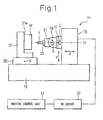
- a machine tool 11 is a five-axis NC milling machine which comprises a bed 13 fixed onto a floor of a factory.
- a column 15 is mounted to the upper face of the bed 13 for linear motion relative to the bed 13 in a horizontal longitudinal direction (the direction of Z-axis, i.e., the right-and-left direction in Figure 1 ).
- a head stock 17 is mounted to the front face of the column 15 for linear motion relative to the column 15 in the vertical direction (the direction of Y-axis, i.e., the up-and-down direction in Figure 1 ).
- the machine tool 11 includes X-, Y- and Z-axis feed motors for moving a workpiece W relative to a tool T in the directions of X-, Y- and Z-axes, an NC device 39 for controlling the X-, Y- and Z-axis feed motors, and a machine control unit 41 which reads a machining program and sends motion commands to the NC device 39 and tool change commands to the machine tool 11, respectively.
- a swivel base 19 is mounted to the head stock 17 for rotation about Z-axis, i.e., C-rotary axis.
- a C-rotary axis feed motor 35 shown in Figure 2
- a rotary encoder 37 for reading the rotational position of the swivel base 19 about the C-rotary axis.
- a braking device (not shown) may be provided.
- an electromagnetic brake may be provided.
- the swivel base 19 includes a housing defining a pair of arm portions 19a and 19b arranged in parallel and a base portion 19c connecting the arm portions 19a and 19b.
- a spindle head 21 is connected between the pair of arms 19a, 19b for rotation about a rotary feed axis (A-rotary axis) perpendicular to the C-rotary axis.
- Incorporated in the swivel base 19 are an A-rotary axis feed motor 29 for rotating the spindle head 21 about the A-rotary axis and a rotary encoder 31 for reading the rotational position of the spindle head 21 about the A-rotary axis.
- a braking device preferably an electromagnetic brake 33 for fixing the spindle head 21 at an rotational position about the A-axis may be provided.
- the A-rotary axis feed motor 29 and the C-rotary axis feed motor 35 are controlled by the NC device 39. Further, the braking device 33 may be controlled by the machine control unit 41.
- the spindle head 21 rotatably holds a main spindle 23 having a tool attaching hole 23a used for attaching the tool T.
- a main spindle motor (not shown) for rotationally driving the main spindle 23 is incorporated in the spindle head 21.
- the main spindle 23 defines a rotary axis O, which is parallel to the Z-axis when the spindle head 21 is positioned at a neutral position relative to the swivel base 19.
- a table 25 is mounted for linear motion relative to the bed 13 in a horizontal direction perpendicular to the Z-axis (the direction of X-axis perpendicular to the plane of Figure 1 ).
- a workpiece mount 27 defining a mounting face 27a to which a workpiece W is fixed.
- polygonal line Pt indicates a tool route in the cutting process.
- the A-rotary axis feed motor 29 is controlled by the NC device 39 so that the spindle head 21 can be maintained at a predetermined rotational position about the A-rotary axis, for example, so that the spindle head 21 can be maintained at a neutral position where the central axis of the tool T becomes parallel with the Z-axis.
- the C-rotary axis feed motor 35 is controlled by the NC device 39 so that the A-rotary axis can be perpendicular to the movement direction Pt of the tool T in the machining process.
- the machine control unit 41 continues to monitor the electric power supplied to the A-rotary axis feed motor 29. According to the present embodiment, the machine control unit 41 will send a command to the NC device to cut off the electric power supplied to the A-rotary axis feed motor 29, when breakage of the tool T or collision of the tool T with the workpiece W occurs and the electric current to the A-rotary axis feed motor 29 exceeds a predetermined threshold value in order to maintain the spindle head 21 at a predetermined angular position about the A-rosary axis.
- the machine control unit 41 monitors the torque acting on the braking device 33 about the A-rotary axis, and when the torque exceeds a predetermined threshold value, the machine control unit 41 releases the braking device 33, and at the same time, cuts off the electric power supplied to the A-rotary axis feed motor 29.
- the A-rotary axis is controlled so as to move the tool T in the reverse direction to the previous feed direction Pt when the electric current supplied to the A-rotary axis feed motor 29 or the degree of torque about the A-rotary axis exceeds a predetermined threshold value.
- the tool T is rotated about the A-rotary axis together with the spindle head 21 whereby the machine tool 11 is prevented from being damaged when collision of the tool T with the workpiece W or breakage of the tool T occurs.
- Figure 1 shows a horizontal type NC milling machine.
- a person skilled in the art may envisage that the present invention can be applied to a vertical type NC milling machine.
Landscapes
- Engineering & Computer Science (AREA)
- Mechanical Engineering (AREA)
- Human Computer Interaction (AREA)
- Manufacturing & Machinery (AREA)
- Physics & Mathematics (AREA)
- General Physics & Mathematics (AREA)
- Automation & Control Theory (AREA)
- Numerical Control (AREA)
- Machine Tool Sensing Apparatuses (AREA)
- Rehabilitation Tools (AREA)
Abstract
Description
- The present invention relates to a machine tool. More particularly, the present invention relates to a machining method and a machine tool, improved to prevent a machine tool from being damaged by an overload due to a collision of a tool with a workpiece or by a breakage of a tool.
- An excessively large force may be applied to a main spindle of a machine tool such as an NC milling machine, when a tool is broken during a process for machining a workpiece or when a tool collides with the workpiece.
- In order to prevent the above problems, for example,
JP-A-3-3687 - However, in the above prior art, since the reverse command is given to the servomotor after collision has been detected, the driven body continues to move in the previous direction even after the collision. Therefore, it is impossible to completely prevent breakage of the machine tool.
- Therefore, the present invention is directed to solve the above problems of the prior art, and the object of the present invention is to provide a machine tool and a machining method improved to surely prevent a machine tool from damage at the time of breakage of a tool or collision of a tool with a workpiece.
- In order to accomplish the above object, the present invention provides a machining method executed with a five-axis machine tool having orthogonal first, second and third linear feed axes and orthogonal first and second rotary feed axes, the first rotary feed axis being parallel to the first linear feed axis, comprising the steps of controlling the first rotary feed axis so as to maintain a rotational axis line of the second rotary feed axis perpendicular to the feed direction of a tool relative to a workpiece while the tool and the workpiece are relatively moved along the second and the third linear feed axes and the workpiece is machined with the tool; and de-energizing a second rotary feed axis motor when the degree of torque about the second rotary feed axis or the electric current to the motor exceeds a predetermined threshold value.
- According to another feature of the present invention, there is provided a machining method executed with a five-axis machine tool having orthogonal first, second and third linear feed axes and orthogonal first and second rotary feed axes, a rotational axis line of the first rotary feed axis being parallel to the first linear feed axis, the machine tool including a table for fixing a workpiece; a main spindle for holding a tool so that the tool faces the table; a spindle head for holding the main spindle for rotation; and first and second feed motors for rotating the spindle head about the first and the second rotary feed axes; the method comprising the steps of controlling the first rotary feed motor so as to maintain a rotational axis line of the second rotary feed axis perpendicular to the feed direction of a tool relative to a workpiece while the tool and the workpiece are relatively moved along the second and the third linear feed axes and the workpiece is machined with the tool; and cutting off the power supply to the second rotary feed motor when the electric current to the motor exceeds a predetermined threshold value in order to maintain the spindle head at the predetermined rotational position.
- Further, according to another feature of the present invention, there is provided a five-axis machine tool having orthogonal first, second and third linear feed axes and orthogonal first and second rotary feed axes, a rotational axis line of the first rotary feed axis being parallel to the first linear feed axis, comprising: a table for fixing a workpiece; a main spindle for holding a tool so that the tool faces the table; a spindle head for holding the main spindle for rotation; a first and a second feed motor for rotating the spindle head about the first and the second rotary feed axes; means for controlling the second feed motor so that the spindle head can be maintained at a predetermined rotational position about the second rotary feed axis; means for controlling the first rotary feed motor to maintain a rotational axis line of the second rotary feed axis perpendicular to the feed direction of the tool with respect to a workpiece during the tool and the workpiece are moved relative to each other in the second and third linear feed axes to machine the workpiece with the tool; and means for cutting off the supply of electric power to the second rotary feed motor when the electric current to the second rotary feed motor exceeds a predetermined value in order to maintain the spindle head at the predetermined rotation position about the second rotary feed axis.
-
-
Figure 1 is a schematic side view of a machine tool of the preferred embodiment of the present invention. -
Figure 2 is a schematic perspective view of a swivel base of the machine tool ofFigure 1 shown together with a spindle head and a main spindle. -
Figure 3 is a schematic illustration for explaining an action of a spindle head at the time of collision of a tool with a workpiece. -
Figure 4 is a diagram showing a relationship between a tool route and the orientation of A-rotary axis for explaining a machining method in the most preferred embodiment of the present invention. - Referring to
Figure 1 , amachine tool 11 according to a preferred embodiment of the present invention is a five-axis NC milling machine which comprises abed 13 fixed onto a floor of a factory. Acolumn 15 is mounted to the upper face of thebed 13 for linear motion relative to thebed 13 in a horizontal longitudinal direction (the direction of Z-axis, i.e., the right-and-left direction inFigure 1 ). A head stock 17 is mounted to the front face of thecolumn 15 for linear motion relative to thecolumn 15 in the vertical direction (the direction of Y-axis, i.e., the up-and-down direction inFigure 1 ). - Although not shown in detail in the drawing, the
machine tool 11 includes X-, Y- and Z-axis feed motors for moving a workpiece W relative to a tool T in the directions of X-, Y- and Z-axes, anNC device 39 for controlling the X-, Y- and Z-axis feed motors, and amachine control unit 41 which reads a machining program and sends motion commands to theNC device 39 and tool change commands to themachine tool 11, respectively. - A
swivel base 19 is mounted to the head stock 17 for rotation about Z-axis, i.e., C-rotary axis. Incorporated in the head stock 17 are a C-rotary axis feed motor 35 (shown inFigure 2 ) for rotating theswivel base 19 about the C-rotary axis and arotary encoder 37 for reading the rotational position of theswivel base 19 about the C-rotary axis. In order to hold theswivel base 19 at a predetermined rotational position about the C-rotary axis, a braking device (not shown) may be provided. Preferably, an electromagnetic brake may be provided. - As shown in
Figure 2 , theswivel base 19 includes a housing defining a pair ofarm portions base portion 19c connecting thearm portions spindle head 21 is connected between the pair ofarms swivel base 19 are an A-rotaryaxis feed motor 29 for rotating thespindle head 21 about the A-rotary axis and a rotary encoder 31 for reading the rotational position of thespindle head 21 about the A-rotary axis. In addition to the A-rotaryaxis feed motor 29, a braking device, preferably anelectromagnetic brake 33 for fixing thespindle head 21 at an rotational position about the A-axis may be provided. - The A-rotary
axis feed motor 29 and the C-rotaryaxis feed motor 35 are controlled by theNC device 39. Further, thebraking device 33 may be controlled by themachine control unit 41. - The
spindle head 21 rotatably holds amain spindle 23 having atool attaching hole 23a used for attaching the tool T. A main spindle motor (not shown) for rotationally driving themain spindle 23 is incorporated in thespindle head 21. Themain spindle 23 defines a rotary axis O, which is parallel to the Z-axis when thespindle head 21 is positioned at a neutral position relative to theswivel base 19. - At a front portion of the
column 15 on the upper face of thebed 13, a table 25 is mounted for linear motion relative to thebed 13 in a horizontal direction perpendicular to the Z-axis (the direction of X-axis perpendicular to the plane ofFigure 1 ). Mounted to the upper face of the table 25 is aworkpiece mount 27 defining amounting face 27a to which a workpiece W is fixed. - With reference to
Figures 3 and 4 , the operation of the present embodiment will be explained below. - In the
machine tool 11, while the tool T and the workpiece W are relatively moved at least in the directions of the X- and Y-axes, the tool T engages with the workpiece W to machine it. InFigure 4 , polygonal line Pt indicates a tool route in the cutting process. In the cutting process, the A-rotaryaxis feed motor 29 is controlled by theNC device 39 so that thespindle head 21 can be maintained at a predetermined rotational position about the A-rotary axis, for example, so that thespindle head 21 can be maintained at a neutral position where the central axis of the tool T becomes parallel with the Z-axis. According to the present embodiment, the C-rotaryaxis feed motor 35 is controlled by theNC device 39 so that the A-rotary axis can be perpendicular to the movement direction Pt of the tool T in the machining process. - In the machining process, the
machine control unit 41 continues to monitor the electric power supplied to the A-rotaryaxis feed motor 29. According to the present embodiment, themachine control unit 41 will send a command to the NC device to cut off the electric power supplied to the A-rotaryaxis feed motor 29, when breakage of the tool T or collision of the tool T with the workpiece W occurs and the electric current to the A-rotaryaxis feed motor 29 exceeds a predetermined threshold value in order to maintain thespindle head 21 at a predetermined angular position about the A-rosary axis. - In the embodiment provided with the
braking device 33 on the A-rotary axis, themachine control unit 41 monitors the torque acting on thebraking device 33 about the A-rotary axis, and when the torque exceeds a predetermined threshold value, themachine control unit 41 releases thebraking device 33, and at the same time, cuts off the electric power supplied to the A-rotaryaxis feed motor 29. - Further, it may be preferable that the A-rotary axis is controlled so as to move the tool T in the reverse direction to the previous feed direction Pt when the electric current supplied to the A-rotary
axis feed motor 29 or the degree of torque about the A-rotary axis exceeds a predetermined threshold value. - Thus, according to the present embodiment, as shown in
Figure 3 , the tool T is rotated about the A-rotary axis together with thespindle head 21 whereby themachine tool 11 is prevented from being damaged when collision of the tool T with the workpiece W or breakage of the tool T occurs. - In this connection.
Figure 1 shows a horizontal type NC milling machine. However, a person skilled in the art may envisage that the present invention can be applied to a vertical type NC milling machine.
Claims (3)
- A machining method executed with a five-axis machine tool having orthogonal first, second and third linear feed axes and orthogonal first and second rotary feed axes, a rotational axis line of the first rotary feed axis being parallel to the first linear feed axis, comprising the steps of:controlling the first rotary feed axis so as to maintain a rotational axis line of the second rotary feed axis perpendicular to the feed direction of a tool relative to a workpiece while the tool and the workpiece are relatively moved along the second and the third linear feed axes and the workpiece is machined with the tool; andde-energizing a second rotary feed axis motor when the degree of torque about the second rotary feed axis or the electric current to the motor exceeds a predetermined threshold value.
- The machining method according to claim 1, wherein the second rotary feed axis is controlled so that the tool can be moved in a direction reverse to the relative moving direction when an intensity of torque or an electric current of the motor about the second rotary feed axis exceeds a predetermined threshold value.
- A five-axis machine tool having orthogonal first, second and third linear feed axes and orthogonal first and second rotary feed axes, a rotational axis line of the first rotary feed axis being parallel to the first linear feed axis, comprising:a table for fixing a workpiece;a main spindle for holding a tool so that the tool faces the table;a spindle head for holding the main spindle for rotation;a first and a second feed motor for rotating the spindle head about the first and the second rotary feed axes;means for controlling the second feed motor so that the spindle head can be maintained at a predetermined rotational position about the second rotary feed axis;means for controlling the first rotary feed motor to maintain a rotational axis line of the second rotary feed axis perpendicular to the feed direction of the tool with respect to a workpiece during the tool and the workpiece are moved relative to each other in the second and third linear feed axes to machine the workpiece witch the tool; andmeans for cutting off the supply of electric power to the second rotary feed motor when the electric current to the second rotary feed motor exceeds a predetermined value in order to maintain the spindle head at the predetermined rotation position about the second rotary feed axis.
Applications Claiming Priority (1)
| Application Number | Priority Date | Filing Date | Title |
|---|---|---|---|
| PCT/JP2008/054240 WO2009110101A1 (en) | 2008-03-04 | 2008-03-04 | Machining method and machine tool |
Publications (3)
| Publication Number | Publication Date |
|---|---|
| EP2253421A1 true EP2253421A1 (en) | 2010-11-24 |
| EP2253421A4 EP2253421A4 (en) | 2016-11-23 |
| EP2253421B1 EP2253421B1 (en) | 2018-03-14 |
Family
ID=41055679
Family Applications (1)
| Application Number | Title | Priority Date | Filing Date |
|---|---|---|---|
| EP08721656.0A Not-in-force EP2253421B1 (en) | 2008-03-04 | 2008-03-04 | Machining method and machine tool |
Country Status (5)
| Country | Link |
|---|---|
| US (1) | US8668412B2 (en) |
| EP (1) | EP2253421B1 (en) |
| JP (1) | JP5253493B2 (en) |
| CA (1) | CA2717213C (en) |
| WO (1) | WO2009110101A1 (en) |
Cited By (4)
| Publication number | Priority date | Publication date | Assignee | Title |
|---|---|---|---|---|
| CN102554700A (en) * | 2011-12-22 | 2012-07-11 | 沈机集团昆明机床股份有限公司 | Method for measuring pre-tightened torque of double-motor clearance elimination mechanism of numerical control machine tool on basis of current signals |
| KR101308041B1 (en) * | 2011-04-07 | 2013-09-12 | 주식회사 국제이엔지 | 3-axes milling head for a machine tool |
| CN109286352A (en) * | 2017-07-19 | 2019-01-29 | 发那科株式会社 | Servo motor control unit |
| CN110480421A (en) * | 2019-08-08 | 2019-11-22 | 沈阳马卡智工科技有限公司 | A kind of horizontal five-axis robot lathe |
Families Citing this family (12)
| Publication number | Priority date | Publication date | Assignee | Title |
|---|---|---|---|---|
| US20110280674A1 (en) * | 2008-05-09 | 2011-11-17 | Ady Palti | Machining device for producing a drilling jig for dental implants |
| CN101862977B (en) * | 2010-05-14 | 2013-07-03 | 沈阳展宏机床有限公司 | Electrical control system of horizontal type boring-milling machine |
| US9545687B2 (en) | 2010-12-17 | 2017-01-17 | Hobart Brothers Company | Spool gun adapter |
| ES2426323B1 (en) * | 2012-03-20 | 2014-09-02 | Gepro Systems, S.L. | MILLING MACHINE |
| CN102699771B (en) * | 2012-05-18 | 2016-12-14 | 南安市瑜鼎投资管理有限公司 | A kind of horizontal digital-control five axle bores milling tapping special machine |
| JP6214664B2 (en) * | 2013-09-13 | 2017-10-18 | 株式会社牧野フライス製作所 | Machine tool feed shaft device |
| JP6498908B2 (en) * | 2014-10-29 | 2019-04-10 | キタムラ機械株式会社 | Machining center operation method |
| CA3035690A1 (en) * | 2018-03-06 | 2019-09-06 | Eric A. Berube | Corner profiling guide |
| EP3579066B1 (en) * | 2018-06-06 | 2026-01-28 | Agie Charmilles SA | Collision protection method |
| CN111113122B (en) * | 2020-01-22 | 2025-09-23 | 科德数控股份有限公司 | A blade disk processing center |
| CN118023987A (en) * | 2024-02-22 | 2024-05-14 | 巨冈精工(广东)股份有限公司 | Double-five-axis horizontal machining center |
| CN118951772A (en) * | 2024-08-28 | 2024-11-15 | 湖北山铁智能装备有限公司 | A non-orthogonal five-axis rotary table |
Family Cites Families (17)
| Publication number | Priority date | Publication date | Assignee | Title |
|---|---|---|---|---|
| KR860000144B1 (en) * | 1981-11-20 | 1986-02-27 | 도시오 미끼야 | Drilling machine having an electromagnetic base |
| JPS58177210A (en) * | 1982-04-05 | 1983-10-17 | Nitto Giken Kk | Drill |
| JPH033687A (en) | 1989-05-31 | 1991-01-09 | Fanuc Ltd | Method of preventing collision damage of body driven by servo motor |
| JP2506214B2 (en) * | 1990-01-17 | 1996-06-12 | オークマ株式会社 | Numerically controlled machine tool collision detection device |
| JPH06289917A (en) * | 1993-03-30 | 1994-10-18 | Fanuc Ltd | Servo motor control method by estimated disturbance load torque |
| JPH07328896A (en) * | 1994-06-07 | 1995-12-19 | Ando Electric Co Ltd | Tool breakage detecting method for nc work machine |
| US5584621A (en) * | 1995-06-13 | 1996-12-17 | Bertsche Engineering Corp. | Direct drive multiple axes rotary spindle head for milling machine |
| US5808888A (en) * | 1996-01-11 | 1998-09-15 | Thermwood Corporation | Method and apparatus for programming a CNC machine |
| JPH11138380A (en) * | 1997-11-11 | 1999-05-25 | Makino Milling Mach Co Ltd | Machine tools with a function to prevent damage in the event of a collision |
| EP1038630A1 (en) * | 1999-03-26 | 2000-09-27 | Industrias Anayak, S.A. | Milling head with direct drive for continuous rotations around two axles |
| JP3829559B2 (en) * | 1999-11-29 | 2006-10-04 | 三菱電機株式会社 | Numerically controlled machine tool |
| JP2002001633A (en) * | 2000-06-19 | 2002-01-08 | Murata Mach Ltd | Working machine having abnormal load detecting function |
| DE102005043835A1 (en) * | 2005-09-13 | 2007-03-22 | F. Zimmermann Gmbh | Movable milling head with torque motor drive |
| DE102007032826A1 (en) * | 2006-07-18 | 2008-01-24 | Franz Kessler Gmbh | Rotating head for a machine tool comprises a stator unit mounted laterally on fork arms |
| DE102006054475A1 (en) * | 2006-11-18 | 2008-05-21 | Hs-Beteiligungsgesellschaft Mbh | Transmission-less, direct propelled multi-axle rotating head for numerically controlled position movement of motor spindle, has motor arranged in hole in arm, where stator of motor is designed for controlling swiveling movement of spindle |
| US7293340B1 (en) * | 2006-12-15 | 2007-11-13 | Roundtop Machinery Industries Co., Ltd | Direct drive spindle, machining center and methods of fabricating the same |
| DE102010037737B4 (en) * | 2010-09-23 | 2012-09-06 | F. Zimmermann Gmbh | Turret for a machine tool spindle |
-
2008
- 2008-03-04 EP EP08721656.0A patent/EP2253421B1/en not_active Not-in-force
- 2008-03-04 US US12/920,513 patent/US8668412B2/en not_active Expired - Fee Related
- 2008-03-04 WO PCT/JP2008/054240 patent/WO2009110101A1/en not_active Ceased
- 2008-03-04 JP JP2010501752A patent/JP5253493B2/en active Active
- 2008-03-04 CA CA2717213A patent/CA2717213C/en active Active
Non-Patent Citations (1)
| Title |
|---|
| See references of WO2009110101A1 * |
Cited By (5)
| Publication number | Priority date | Publication date | Assignee | Title |
|---|---|---|---|---|
| KR101308041B1 (en) * | 2011-04-07 | 2013-09-12 | 주식회사 국제이엔지 | 3-axes milling head for a machine tool |
| CN102554700A (en) * | 2011-12-22 | 2012-07-11 | 沈机集团昆明机床股份有限公司 | Method for measuring pre-tightened torque of double-motor clearance elimination mechanism of numerical control machine tool on basis of current signals |
| CN102554700B (en) * | 2011-12-22 | 2014-05-14 | 沈机集团昆明机床股份有限公司 | Method for measuring pre-tightened torque of double-motor clearance elimination mechanism of numerical control machine tool on basis of current signals |
| CN109286352A (en) * | 2017-07-19 | 2019-01-29 | 发那科株式会社 | Servo motor control unit |
| CN110480421A (en) * | 2019-08-08 | 2019-11-22 | 沈阳马卡智工科技有限公司 | A kind of horizontal five-axis robot lathe |
Also Published As
| Publication number | Publication date |
|---|---|
| US8668412B2 (en) | 2014-03-11 |
| WO2009110101A1 (en) | 2009-09-11 |
| EP2253421A4 (en) | 2016-11-23 |
| CA2717213C (en) | 2012-09-04 |
| CA2717213A1 (en) | 2009-09-11 |
| EP2253421B1 (en) | 2018-03-14 |
| JP5253493B2 (en) | 2013-07-31 |
| US20110014001A1 (en) | 2011-01-20 |
| JPWO2009110101A1 (en) | 2011-07-14 |
Similar Documents
| Publication | Publication Date | Title |
|---|---|---|
| US8668412B2 (en) | Machining method and machine tool | |
| EP2319656B1 (en) | Grinding machine | |
| US20180056465A1 (en) | Fluid ejection device | |
| JP2002137070A (en) | Composite machining apparatus and friction stir welding method | |
| EP1982793A1 (en) | Universal head and machine tool with universal head | |
| CN106476009B (en) | Machine with a movable working part | |
| CN208178927U (en) | A Composite CNC Machine Tool with Multi-Axis Turning and Milling Function | |
| US20240058915A1 (en) | Machine Tool, Method of Estimating Force Applied to Tool, and Program for Estimating Force Applied to Tool | |
| US6840896B2 (en) | Attachment of machine tool and machine tool | |
| JP3969664B2 (en) | Numerically controlled machine tool and machining program check method | |
| JPH11165211A (en) | Inner face machining machine | |
| JPH089124B2 (en) | Free curved surface processing method | |
| US6163735A (en) | Numerically controlled machine tool | |
| JP2007229849A (en) | End mill and processing method using the same | |
| JP5915101B2 (en) | Machine Tools | |
| JPH10143213A (en) | Multi-surface working machine and multi-surface working method | |
| JP4266791B2 (en) | Machining method | |
| KR100738390B1 (en) | AC Column Embedded Ultra Narrow Vertical Machining Center | |
| WO2019102561A1 (en) | Machine tool | |
| JP7085076B1 (en) | Machine tools, control methods, and control programs | |
| JP2001138176A (en) | Diagonal hole machining method, and nc machining device | |
| KR20230111243A (en) | Assemblies and devices for machining machine parts | |
| JP2002331433A (en) | Cutting work unit | |
| CN218856328U (en) | Numerical control machine tool feed shaft control structure | |
| KR100655310B1 (en) | Automatic clamp and unclamp device and method of gravity shaft |
Legal Events
| Date | Code | Title | Description |
|---|---|---|---|
| PUAI | Public reference made under article 153(3) epc to a published international application that has entered the european phase |
Free format text: ORIGINAL CODE: 0009012 |
|
| 17P | Request for examination filed |
Effective date: 20100902 |
|
| AK | Designated contracting states |
Kind code of ref document: A1 Designated state(s): AT BE BG CH CY CZ DE DK EE ES FI FR GB GR HR HU IE IS IT LI LT LU LV MC MT NL NO PL PT RO SE SI SK TR |
|
| AX | Request for extension of the european patent |
Extension state: AL BA MK RS |
|
| DAX | Request for extension of the european patent (deleted) | ||
| RA4 | Supplementary search report drawn up and despatched (corrected) |
Effective date: 20161021 |
|
| RIC1 | Information provided on ipc code assigned before grant |
Ipc: B23Q 11/04 20060101ALI20161017BHEP Ipc: B23Q 15/007 20060101ALI20161017BHEP Ipc: G05B 19/4062 20060101AFI20161017BHEP Ipc: B23Q 5/58 20060101ALI20161017BHEP |
|
| REG | Reference to a national code |
Ref country code: DE Ref legal event code: R079 Ref document number: 602008054426 Country of ref document: DE Free format text: PREVIOUS MAIN CLASS: B23Q0005580000 Ipc: G05B0019406200 |
|
| RIC1 | Information provided on ipc code assigned before grant |
Ipc: B23Q 15/007 20060101ALI20170628BHEP Ipc: B23Q 11/04 20060101ALI20170628BHEP Ipc: B23Q 5/58 20060101ALI20170628BHEP Ipc: G05B 19/4062 20060101AFI20170628BHEP |
|
| GRAP | Despatch of communication of intention to grant a patent |
Free format text: ORIGINAL CODE: EPIDOSNIGR1 |
|
| STAA | Information on the status of an ep patent application or granted ep patent |
Free format text: STATUS: GRANT OF PATENT IS INTENDED |
|
| INTG | Intention to grant announced |
Effective date: 20170830 |
|
| GRAS | Grant fee paid |
Free format text: ORIGINAL CODE: EPIDOSNIGR3 |
|
| GRAA | (expected) grant |
Free format text: ORIGINAL CODE: 0009210 |
|
| STAA | Information on the status of an ep patent application or granted ep patent |
Free format text: STATUS: THE PATENT HAS BEEN GRANTED |
|
| AK | Designated contracting states |
Kind code of ref document: B1 Designated state(s): AT BE BG CH CY CZ DE DK EE ES FI FR GB GR HR HU IE IS IT LI LT LU LV MC MT NL NO PL PT RO SE SI SK TR |
|
| REG | Reference to a national code |
Ref country code: GB Ref legal event code: FG4D |
|
| REG | Reference to a national code |
Ref country code: CH Ref legal event code: EP Ref country code: AT Ref legal event code: REF Ref document number: 979475 Country of ref document: AT Kind code of ref document: T Effective date: 20180315 |
|
| REG | Reference to a national code |
Ref country code: IE Ref legal event code: FG4D |
|
| REG | Reference to a national code |
Ref country code: DE Ref legal event code: R096 Ref document number: 602008054426 Country of ref document: DE |
|
| REG | Reference to a national code |
Ref country code: NL Ref legal event code: MP Effective date: 20180314 |
|
| REG | Reference to a national code |
Ref country code: LT Ref legal event code: MG4D |
|
| PG25 | Lapsed in a contracting state [announced via postgrant information from national office to epo] |
Ref country code: FI Free format text: LAPSE BECAUSE OF FAILURE TO SUBMIT A TRANSLATION OF THE DESCRIPTION OR TO PAY THE FEE WITHIN THE PRESCRIBED TIME-LIMIT Effective date: 20180314 Ref country code: LT Free format text: LAPSE BECAUSE OF FAILURE TO SUBMIT A TRANSLATION OF THE DESCRIPTION OR TO PAY THE FEE WITHIN THE PRESCRIBED TIME-LIMIT Effective date: 20180314 Ref country code: NO Free format text: LAPSE BECAUSE OF FAILURE TO SUBMIT A TRANSLATION OF THE DESCRIPTION OR TO PAY THE FEE WITHIN THE PRESCRIBED TIME-LIMIT Effective date: 20180614 Ref country code: HR Free format text: LAPSE BECAUSE OF FAILURE TO SUBMIT A TRANSLATION OF THE DESCRIPTION OR TO PAY THE FEE WITHIN THE PRESCRIBED TIME-LIMIT Effective date: 20180314 Ref country code: ES Free format text: LAPSE BECAUSE OF FAILURE TO SUBMIT A TRANSLATION OF THE DESCRIPTION OR TO PAY THE FEE WITHIN THE PRESCRIBED TIME-LIMIT Effective date: 20180314 Ref country code: CY Free format text: LAPSE BECAUSE OF FAILURE TO SUBMIT A TRANSLATION OF THE DESCRIPTION OR TO PAY THE FEE WITHIN THE PRESCRIBED TIME-LIMIT Effective date: 20180314 |
|
| REG | Reference to a national code |
Ref country code: AT Ref legal event code: MK05 Ref document number: 979475 Country of ref document: AT Kind code of ref document: T Effective date: 20180314 |
|
| PG25 | Lapsed in a contracting state [announced via postgrant information from national office to epo] |
Ref country code: GR Free format text: LAPSE BECAUSE OF FAILURE TO SUBMIT A TRANSLATION OF THE DESCRIPTION OR TO PAY THE FEE WITHIN THE PRESCRIBED TIME-LIMIT Effective date: 20180615 Ref country code: LV Free format text: LAPSE BECAUSE OF FAILURE TO SUBMIT A TRANSLATION OF THE DESCRIPTION OR TO PAY THE FEE WITHIN THE PRESCRIBED TIME-LIMIT Effective date: 20180314 Ref country code: SE Free format text: LAPSE BECAUSE OF FAILURE TO SUBMIT A TRANSLATION OF THE DESCRIPTION OR TO PAY THE FEE WITHIN THE PRESCRIBED TIME-LIMIT Effective date: 20180314 Ref country code: BG Free format text: LAPSE BECAUSE OF FAILURE TO SUBMIT A TRANSLATION OF THE DESCRIPTION OR TO PAY THE FEE WITHIN THE PRESCRIBED TIME-LIMIT Effective date: 20180614 |
|
| PG25 | Lapsed in a contracting state [announced via postgrant information from national office to epo] |
Ref country code: EE Free format text: LAPSE BECAUSE OF FAILURE TO SUBMIT A TRANSLATION OF THE DESCRIPTION OR TO PAY THE FEE WITHIN THE PRESCRIBED TIME-LIMIT Effective date: 20180314 Ref country code: RO Free format text: LAPSE BECAUSE OF FAILURE TO SUBMIT A TRANSLATION OF THE DESCRIPTION OR TO PAY THE FEE WITHIN THE PRESCRIBED TIME-LIMIT Effective date: 20180314 Ref country code: NL Free format text: LAPSE BECAUSE OF FAILURE TO SUBMIT A TRANSLATION OF THE DESCRIPTION OR TO PAY THE FEE WITHIN THE PRESCRIBED TIME-LIMIT Effective date: 20180314 Ref country code: PL Free format text: LAPSE BECAUSE OF FAILURE TO SUBMIT A TRANSLATION OF THE DESCRIPTION OR TO PAY THE FEE WITHIN THE PRESCRIBED TIME-LIMIT Effective date: 20180314 |
|
| PG25 | Lapsed in a contracting state [announced via postgrant information from national office to epo] |
Ref country code: CZ Free format text: LAPSE BECAUSE OF FAILURE TO SUBMIT A TRANSLATION OF THE DESCRIPTION OR TO PAY THE FEE WITHIN THE PRESCRIBED TIME-LIMIT Effective date: 20180314 Ref country code: SK Free format text: LAPSE BECAUSE OF FAILURE TO SUBMIT A TRANSLATION OF THE DESCRIPTION OR TO PAY THE FEE WITHIN THE PRESCRIBED TIME-LIMIT Effective date: 20180314 Ref country code: AT Free format text: LAPSE BECAUSE OF FAILURE TO SUBMIT A TRANSLATION OF THE DESCRIPTION OR TO PAY THE FEE WITHIN THE PRESCRIBED TIME-LIMIT Effective date: 20180314 |
|
| REG | Reference to a national code |
Ref country code: DE Ref legal event code: R097 Ref document number: 602008054426 Country of ref document: DE |
|
| PG25 | Lapsed in a contracting state [announced via postgrant information from national office to epo] |
Ref country code: PT Free format text: LAPSE BECAUSE OF FAILURE TO SUBMIT A TRANSLATION OF THE DESCRIPTION OR TO PAY THE FEE WITHIN THE PRESCRIBED TIME-LIMIT Effective date: 20180716 |
|
| PLBE | No opposition filed within time limit |
Free format text: ORIGINAL CODE: 0009261 |
|
| STAA | Information on the status of an ep patent application or granted ep patent |
Free format text: STATUS: NO OPPOSITION FILED WITHIN TIME LIMIT |
|
| PG25 | Lapsed in a contracting state [announced via postgrant information from national office to epo] |
Ref country code: DK Free format text: LAPSE BECAUSE OF FAILURE TO SUBMIT A TRANSLATION OF THE DESCRIPTION OR TO PAY THE FEE WITHIN THE PRESCRIBED TIME-LIMIT Effective date: 20180314 |
|
| 26N | No opposition filed |
Effective date: 20181217 |
|
| PG25 | Lapsed in a contracting state [announced via postgrant information from national office to epo] |
Ref country code: SI Free format text: LAPSE BECAUSE OF FAILURE TO SUBMIT A TRANSLATION OF THE DESCRIPTION OR TO PAY THE FEE WITHIN THE PRESCRIBED TIME-LIMIT Effective date: 20180314 |
|
| PG25 | Lapsed in a contracting state [announced via postgrant information from national office to epo] |
Ref country code: MC Free format text: LAPSE BECAUSE OF FAILURE TO SUBMIT A TRANSLATION OF THE DESCRIPTION OR TO PAY THE FEE WITHIN THE PRESCRIBED TIME-LIMIT Effective date: 20180314 |
|
| REG | Reference to a national code |
Ref country code: CH Ref legal event code: PL |
|
| PG25 | Lapsed in a contracting state [announced via postgrant information from national office to epo] |
Ref country code: LU Free format text: LAPSE BECAUSE OF NON-PAYMENT OF DUE FEES Effective date: 20190304 |
|
| REG | Reference to a national code |
Ref country code: BE Ref legal event code: MM Effective date: 20190331 |
|
| PG25 | Lapsed in a contracting state [announced via postgrant information from national office to epo] |
Ref country code: LI Free format text: LAPSE BECAUSE OF NON-PAYMENT OF DUE FEES Effective date: 20190331 Ref country code: CH Free format text: LAPSE BECAUSE OF NON-PAYMENT OF DUE FEES Effective date: 20190331 Ref country code: IE Free format text: LAPSE BECAUSE OF NON-PAYMENT OF DUE FEES Effective date: 20190304 |
|
| PG25 | Lapsed in a contracting state [announced via postgrant information from national office to epo] |
Ref country code: BE Free format text: LAPSE BECAUSE OF NON-PAYMENT OF DUE FEES Effective date: 20190331 |
|
| PG25 | Lapsed in a contracting state [announced via postgrant information from national office to epo] |
Ref country code: TR Free format text: LAPSE BECAUSE OF FAILURE TO SUBMIT A TRANSLATION OF THE DESCRIPTION OR TO PAY THE FEE WITHIN THE PRESCRIBED TIME-LIMIT Effective date: 20180314 |
|
| PG25 | Lapsed in a contracting state [announced via postgrant information from national office to epo] |
Ref country code: MT Free format text: LAPSE BECAUSE OF NON-PAYMENT OF DUE FEES Effective date: 20190304 |
|
| PG25 | Lapsed in a contracting state [announced via postgrant information from national office to epo] |
Ref country code: IS Free format text: LAPSE BECAUSE OF FAILURE TO SUBMIT A TRANSLATION OF THE DESCRIPTION OR TO PAY THE FEE WITHIN THE PRESCRIBED TIME-LIMIT Effective date: 20180714 |
|
| PG25 | Lapsed in a contracting state [announced via postgrant information from national office to epo] |
Ref country code: HU Free format text: LAPSE BECAUSE OF FAILURE TO SUBMIT A TRANSLATION OF THE DESCRIPTION OR TO PAY THE FEE WITHIN THE PRESCRIBED TIME-LIMIT; INVALID AB INITIO Effective date: 20080304 |
|
| PGFP | Annual fee paid to national office [announced via postgrant information from national office to epo] |
Ref country code: DE Payment date: 20240130 Year of fee payment: 17 Ref country code: GB Payment date: 20240201 Year of fee payment: 17 |
|
| PGFP | Annual fee paid to national office [announced via postgrant information from national office to epo] |
Ref country code: IT Payment date: 20240212 Year of fee payment: 17 Ref country code: FR Payment date: 20240213 Year of fee payment: 17 |
|
| REG | Reference to a national code |
Ref country code: DE Ref legal event code: R119 Ref document number: 602008054426 Country of ref document: DE |
|
| GBPC | Gb: european patent ceased through non-payment of renewal fee |
Effective date: 20250304 |
|
| PG25 | Lapsed in a contracting state [announced via postgrant information from national office to epo] |
Ref country code: DE Free format text: LAPSE BECAUSE OF NON-PAYMENT OF DUE FEES Effective date: 20251001 |
|
| PG25 | Lapsed in a contracting state [announced via postgrant information from national office to epo] |
Ref country code: GB Free format text: LAPSE BECAUSE OF NON-PAYMENT OF DUE FEES Effective date: 20250304 |
|
| PG25 | Lapsed in a contracting state [announced via postgrant information from national office to epo] |
Ref country code: IT Free format text: LAPSE BECAUSE OF NON-PAYMENT OF DUE FEES Effective date: 20250304 Ref country code: FR Free format text: LAPSE BECAUSE OF NON-PAYMENT OF DUE FEES Effective date: 20250331 |